Embed Size (px)
Citation preview

Successful Design and Operation of 700MW Class
(3 Casing) Steam Turbine
Seong Heon Yang, Ph.D.
Chief Engineer
Steam Turbine Engineering Team 1
For NTPC Conference, 2013

Contents
1
Project Overview
Introduction of Turbine
Design Results
Design Verification
Application of Lesson Learned
Operation Results

Project Overview
2
Gheco-one
Rating x Unit / Hz : 700MW x 1 Unit / 50 Hz
Plant Type : Supercritical Fossil Fired Power Plant
Site: Rayong (about 180km southeast of Bangkok, Thailand)
Customer: GHECO (Glow Hemaraj Energy Co.,Ltd)
Cirebon
Rating x Unit / Hz : 698MW x 1 Unit / 50 Hz
Plant Type : Supercritical Fossil Fired Power Plant
Site: Cirebon (about 250km south of Jakarta, Indonesia)
Customer: PT CEP (PT Cirebon Electrical Power)

Project Overview – Gheco-one, Thailand
3
Introduction of Turbine
4
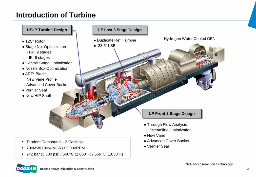
HP/IP Turbine Design
12Cr Rotor
Stage No. Optimization
HP: 9 stages
IP: 8 stages
Control Stage Optimization
Nozzle Box Optimization
ART* Blade
New Vane Profile
Advanced Cover Bucket
Vernier Seal
New HIP Shell
LP Front 3 Stage Design
Through Flow Analysis
Streamline Optimization
New Vane
Advanced Cover Bucket
Vernier Seal
LP Last 3 Stage Design
Duplicate Ref. Turbine
33.5” LSB
*Advanced Reaction Technology
Hydrogen Water Cooled GEN
Tandem Compound – 3 Casings
700MW(100% MGR) / 3,000RPM
242 bar (3,500 psi) / 566C (1,050F) / 566C (1,050F)

Design Results – Material Specification
5
HP & IP Rotor
Component Material
HP & IP Bucket
HP & IP Diaphragm (Ring/Web)
HP & IP Casing
LP Rotor
LP Bucket
LP Casing
12Cr Alloy Steel
12Cr Alloy Steel
12Cr Alloy Steel
12Cr Alloy Steel
HP & IP, LP Nozzle 12Cr Alloy Steel
NiCrMoV Steel
12Cr Alloy Steel
Carbon Steel
LP Diaphragm (Ring/Web) Carbon Steel
12Cr Alloy steel is applied to the HIP rotor and bucket to satisfy mechanical stress
Steam Condition: 242bar/566°C (HP), 566°C (IP)
Material for other components of HIP turbine is the same as rotor considering thermal
expansion

Design Results – Thermodynamics
6
Turbine configuration design based on the
optimization method
No. of Stage, Root Diameter
Flow angle, Blade width
Packing Dia. Etc.
Detail thermodynamic design based on the
Doosan design rule
Steam Condition and Load at Each Stage
Steam Path Layout
HP 9 stages, IP 8 stages Opposite Flow
(HP/IP Single Casing)
The thermodynamic design results are
conformed by the mechanical reliability
evaluation. (rotor dynamic analysis, bearing
analysis, blade vibratory analysis, etc.)
Stage No 9
Root Dia 40”
PKG Dia 31”
Root Rx 25%
HP Section
46”
Stage No 8
Root Dia
PKG Dia 31”
Root Rx 25%
IP Section
HP Turbine Efficiency Study
86.0
86.5
87.0
87.5
88.0
88.5
89.0
89.5
90.0
90.5
7 8 9 10
No. of Stage
SXS Eff. (%
)
37 rd 39 rd 41 rd
IP Turbine Efficiency Study
92.0
92.2
92.4
92.6
92.8
93.0
93.2
93.4
93.6
93.8
94.0
5 6 7 8 9 10
No. of StageSXS
Eff
. (%
)
40 rd 41 rd 42 rd 43 rd 44 rd 45 rd

Design Results – Aerodynamics
7
Blade Design
Designed by 3-D CFD
Blade Profile Design
High efficiency aerodynamic blade design
based on the thermodynamic design
results(flow angle, reaction, pressure )
2D profile section is verified by Mach
number, pressure distribution along the
profile using blade cascade CFD
Advanced 3D smooth stacking
Blade design using 3D CFD
Cross verifying between in-house design
S/W and commercial 3D CFD S/W (CFX,
Fluent, Numeca)
Optimized blade profile from the detail
understanding of the steam flow around the
blade using 3D CFD analysis
Moving CV

Design Results – Steam Path
8
Control Stage
HIP Bucket Bucket & Diaphragm Rotor & Bucket
New Vane (Application of ART)
Increase of Root Reaction
Change of Flow Angle
Decrease of Profile Loss
Advanced Covered Bucket
Continuous Coupled Design
Improvement of Efficiency & Vibration
Diaphragm
Advanced Multi-tooth Seal
Control Stage
Bucket
Axial Entry Dovetail for High Reliability
Nozzle Box
360° Full Arc

Design Results – HIP/LP Casing
9
3D Thermal/Structural Analysis of HIP Casing
To ensure thermal/structure design reliability
Modal Analysis of LP Casing
To avoid casing resonance during operation
HIP Casing
LP Casing

Design Results – Rotor Dynamics
10
HIP LPA LPB GEN
Full Train T/G FE Modeling
Critical
Speed
(rpm)
Max. Amplitude
of Response
(μm)
Min. Clearance
(μm) Note
HIP 1,740 468 1,372 Max. amplitude of
response at rated
speed(3,000rpm)
is below 38μm.
LP-A 1,420 295 1,524
LP-B 1,520 462 1,524
Result of Unbalance Response Analysis Rotor Stability Margin
Design Results – Layout Design
11
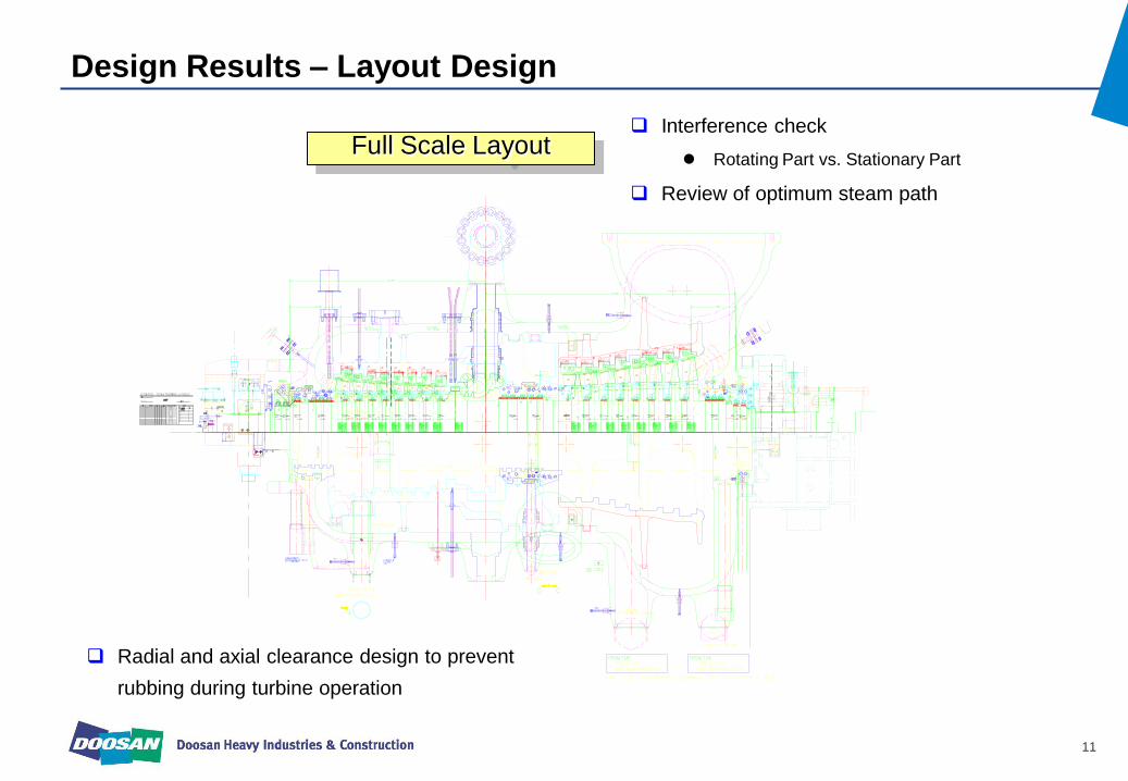
Full Scale Layout
Radial and axial clearance design to prevent
rubbing during turbine operation
Interference check
Rotating Part vs. Stationary Part
Review of optimum steam path

Design Verification
12
Results
• Ensure of structure
reliability in condition of
high temperature/high
pressure operation
• Performance of 3D structural
analysis by ANSYS
• Evaluation of analysis result
compared with reference
turbine
• Stress Margin: 7% higher
than the reference turbine
Nozzle Box
Verification ISSUE Item
X10
1.000R
3D Model and 2D Layout
3D Structural Analysis

Design Verification
13
Results
• To verify stage efficiency
of new LP 1~3 stages
• Performance of CFX multi-stage
analysis
• Evaluation of analysis result
compared with thermodynamic
design efficiency
• Efficiency Margin:
Higher than reference
LP turbine
Flow Analysis
Verification ISSUE Item
Modeling & Mesh 3D Flow Analysis

Design Verification
14
Results Verification ISSUE Item
• Large bearing span of HIP
rotor
• Ensure of rotor
static/dynamic reliability
• Minimization of bearing span for
HIP turbine from the adjustment
of Bucket/Diaphragm width
• Optimization of bearing design
for improving the rotor dynamic
characteristics
• Sufficient design margin for
bending & torsional stress
• Sufficient design margin for
bearing temperature,
pressure, etc.
• Maximum amplitude of
unbalance response at
critical speed(1740rpm) is
below 50% of minimum
clearance.
• Sufficient stability margin
which means the
characteristics of steam
instability for HIP turbine
Rotor Dynamic
Analysis

Application of Lesson Learned
15
Countermeasure
• Rubbing at gland
packing
• Insufficient clearance between
the rotating part and stationary
part
• Improper installation for
stationary part
Existing
Fossil/Nuclear
Turbine
Cause Issue PJT
Rubbing at Top Side of Gland Packing
G01
G02
G03
Applying the Elliptical Offset at LP Packing Ring
• Optimum clearance design
• Adjusting the top/bottom
clearance during installation – Consideration of rotor rising in
journal bearing, vacuum
deflection, etc.
• Change of packing shape

Application of Lesson Learned
16
Countermeasure Cause Issue PJT
• Steam whirl at
MGR(814MW) – Exactly, more than 800MW
• Insufficient stability margin
• Non-reflection for deformation
of turbine supporting system
• Sufficient stability margin - Installation of anti-swirl packing
- Increase of tip seal clearance
- Reduce of T2 bearing length
• Optimized installation
considering the deformation
of turbine supporting system
HP Remedy
Turbine for YH
1/2 Unit
YH 1/2 Unit Stability Margin
Original
Remedy
Modified
Stability
Lower Limit
Gheco-one/Cirebon Stability Margin

Operation Results – Gheco-one Turbine
17
All commissioning test was completed without any troubles such as high rotor vibration,
high bearing metal temperature and abnormal rotor expansion etc.
Turbine Initial Rolling: 2011/10/12
Commissioning Test
Operation at Rated Output, Load Runback, Load Swing, 100% Load Rejection + House Load Operation
Especially, critical high vibration phenomenon such as steam whirl was not occurred
Turbine Operating Data for Gheco-one (Output, Rotating Speed, Vibration)

Operation Results – Cirebon Turbine
18
Operation Results for Turbine
Turbine initial rolling : 2011/12/05
Turbine of Cirebon PJT started commercial operation
after completion of commissioning.
Max. turbine vibration at rated output is below 80um.
Other operating data remained stable.
Data Description
DWATT: Output
TNH_RPM: Rotating Speed
BB1X ~ BB8Y: Vibration at Journal Bearing
TT_G1M1 ~ TT_G8M1: Journal Bearing Metal
Temperature
TT_G1D ~ TT_G8D: Journal Bearing Drain Oil
Temperature
Results of Performance Test
Output: 700 735MW
Efficiency: 1.0% Higher than heat rate in contract
NO. TAG VALUE NO. TAG VALUE
1 DWATT 657.7 35 TT_G1D 64.3
2 TNH_RPM 3001.8 36 TT_G2D 62.0
3 TT_IS 566.0 37 TT_G3D 69.3
4 TT_RHS 566.9 38 TT_G4D 56.5
5 IP_P 255.3 39 TT_G5D 57.4
6 HRHP_P 43.2 40 TT_G7D 57.6
7 BB1X 54.4 41 TT_G8D 55.8
8 BB2X 45.4 42 TT_TAD 64.0
9 BB3X 32.8 43 TT_TID 72.1
10 BB4X 55.6 44 TT_LOCO 47.0
11 BB5X 63.9 45 TT_1SSUI1 528.8
12 BB6X 74.5 46 TT_1SSUI2 521.9
13 BB7X 82.2 47 TT_1SSUI3 509.8
14 BB8X 74.7 48 TT_1SSLI1 531.1
15 BB1Y 51.4 49 TT_ES1 327.6
16 BB2Y 24.4 50 TT_ES2 327.3
17 BB3Y 50.0 51 TT_ES3 328.1
18 BB4Y 33.6 52 TT_HPEXHLI1 338.5
19 BB5Y 16.0 53 TT_HPEXHUI1 324.6
20 BB6Y 25.6 54 T2_HP 511.5
21 BB7Y 52.1 55 T2_RH 559.4
22 BB8Y 25.2 56 T2_XO 318.1
23 TT_G1M1 90.2 57 TT_RHBLI1 569.3
24 TT_G2M1 95.2 58 TT_RHBLI2 560.8
25 TT_G3M1 90.9 59 TT_RHBUI1 559.0
26 TT_G4M1 88.4 60 TT_LPA 43.7
27 TT_G5M1 82.6 61 TT_LPB 43.0
28 TT_G6M1 81.4 62 TT_SSH 290.5
29 TT_G7M1 82.8 63 EV_P 704.3
30 TT_G8M1 74.6 64 Tag not found
31 TT_TAM1 85.7 65 Tag not found
32 TT_TAM2 77.1 66 Tag not found
33 TT_TIM1 71.3 67 Tag not found
34 TT_TIM2 70.2 68 Tag not found