Embed Size (px)
Citation preview

www.radarviewllc.com
Subsurface Void Detection
for thefor the
Foundation Performance Association

www.radarviewllc.com
Causes of subsurface voidsCauses of subsurface voids

www.radarviewllc.com
Causes of subsurface voids
• Expansive soils

www.radarviewllc.com
Causes of subsurface voids
•Poor drainage

www.radarviewllc.com
Causes of subsurface voids
•Poor compaction of soil - wrong way
www.radarviewllc.com
Causes of subsurface voids
•Poor compaction of soil – right way
www.radarviewllc.com
Causes of subsurface voids
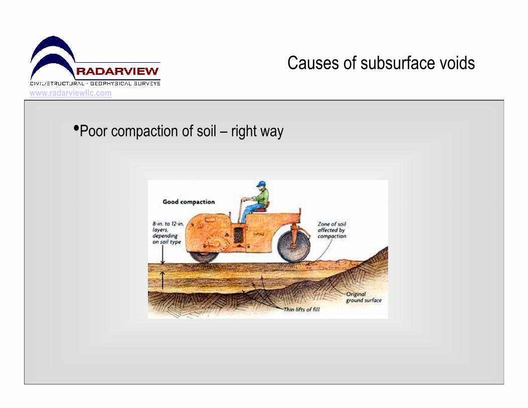
•Poor compaction of soil - effect
Cracks

www.radarviewllc.com
Causes of subsurface voids
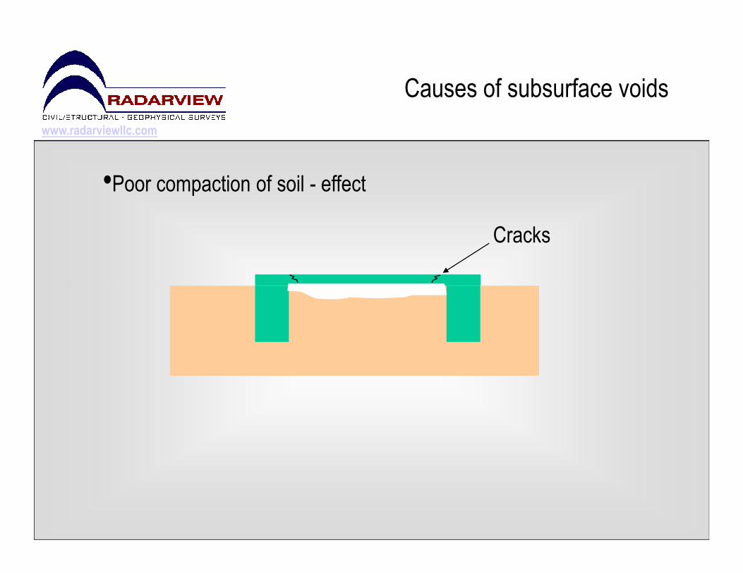
•Leaking Utilities / drainage systems
Differential SettlementDifferential Settlement
www.radarviewllc.com
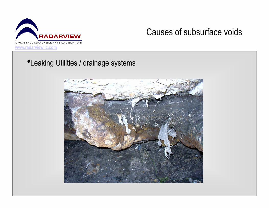
Causes of subsurface voids
•Leaking Utilities / drainage systems
www.radarviewllc.com
Causes of subsurface voids
•Leaking Utilities / drainage systems

www.radarviewllc.com
Causes of subsurface voids
•Leaking Utilities / drainage systems
www.radarviewllc.com
Detection MethodsDetection Methods

www.radarviewllc.com
Detection Methods
•Ground Penetrating Radar (GPR)

www.radarviewllc.com
Detection Methods
Introduction to GPR
•Early usage: Austria 1929, Military 1950’s•1st commercial system developed in the early 1970’s for use in Geotechnical applications
•Advanced 3D Software developed in the late 1990’s •Advanced 3D Software developed in the late 1990’s •Uses Electromagnetic Wave Propagation to measure changes in electrical and magnetic properties
•Allows Non-Intrusive look into or through low-conductivity materials•Used in Geophysical, Structural, Civil, and other industries

www.radarviewllc.com
Detection Methods
Two electrical properties of
importance to GPR surveys
•Electrical Conductivity – effects penetration•Electrical Conductivity – effects penetration
•Electrical Permittivity “Dielectric Constant” – effects the
reflected signal strength
www.radarviewllc.com
Detection Methods
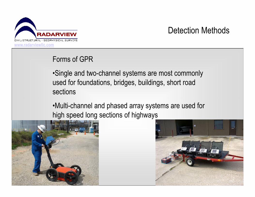
Forms of GPR
•Single and two-channel systems are most commonly
used for foundations, bridges, buildings, short road
sections
•Multi-channel and phased array systems are used for
high speed long sections of highways
www.radarviewllc.com
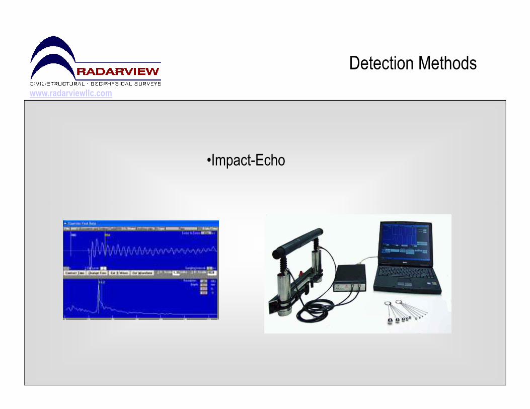
Detection Methods
•Impact-Echo
www.radarviewllc.com
Detection Methods
Introduction to Impact-Echo
•Research began as early as 1983 at the National Bureau of Standards (NBS) now known as National Institute of Standards and Technologies (NIST)
•The first thesis research was performed at NIST and accepted in •The first thesis research was performed at NIST and accepted in 1986 by Cornell University
•1st commercial system was available in 1992•Uses Impact-generated stress waves that propagate through a concrete and masonry structures
•Used in Structural, Civil, and other industries
www.radarviewllc.com
Detection Methods
Impact-Echo
•Stress (sound) waves that propagate through concrete and masonry
are reflected by internal flaws and external surfaces
•Primarily used to determine defects in concrete structures. It can
also locate voids in the subgrade directly beneath slabs and also locate voids in the subgrade directly beneath slabs and
pavements.
•Accurate method, but slower than GPR for voids surveys

www.radarviewllc.com
Detection Methods
Core Drilling
www.radarviewllc.com
Detection Methods
Core Drilling
• Core Drilling – effective to verify a suspect location but
would require many holes in order to “Survey” an area
for voids.for voids.
• Will not give a true indication of the void size in sq. ft.
• Destructive – effects aesthetics, carpet, flooring, cuts
PT cables, rebar & utilities

www.radarviewllc.com
Detection Methods
Order of use:
1. Void survey: GPR
• Used to quickly screen larges areas, providing an
accurate plan view map of voids as well as accurate plan view map of voids as well as
determine the depth
2. Localized prove-up:
• Core Drilling
www.radarviewllc.com
Other Detection Methods
Dynamic Cone Penetrometer – works reasonably well, however it is labor
intensive and inefficient. ASTM STP-399

www.radarviewllc.com
Detection Methods
Proof of concept demonstration
www.radarviewllc.com
Detection Methods
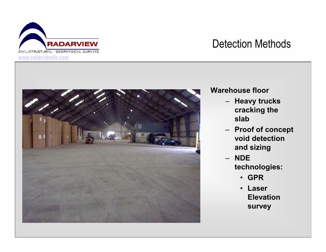
Warehouse floor
– Heavy trucks
cracking the
slab
– Proof of concept – Proof of concept
void detection
and sizing
– NDE
technologies:
• GPR
• Laser
Elevation
survey
www.radarviewllc.com
Detection Methods
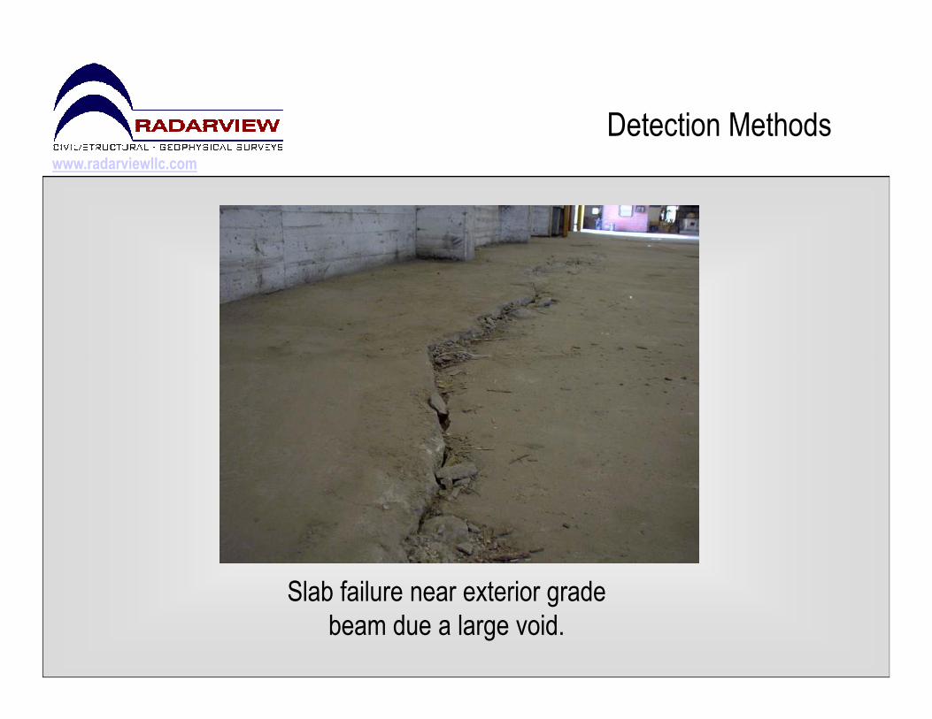
Slab failure near exterior grade
beam due a large void.

www.radarviewllc.com
Detection Methods
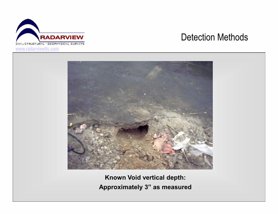
Scan Area
Known Void
www.radarviewllc.com
Detection Methods
Known Void vertical depth:
Approximately 3” as measured
www.radarviewllc.com
Detection Methods
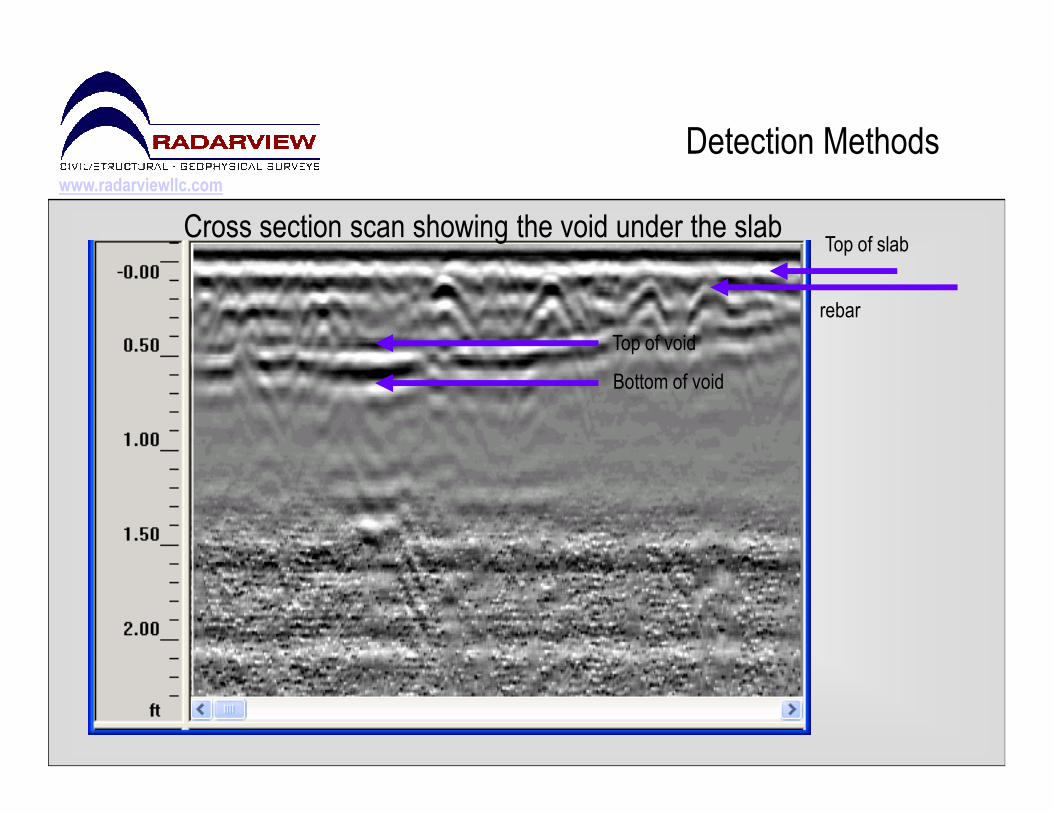
Cross section scan showing the void under the slabTop of slab
rebar
Top of void
Bottom of void
www.radarviewllc.com
Detection Methods
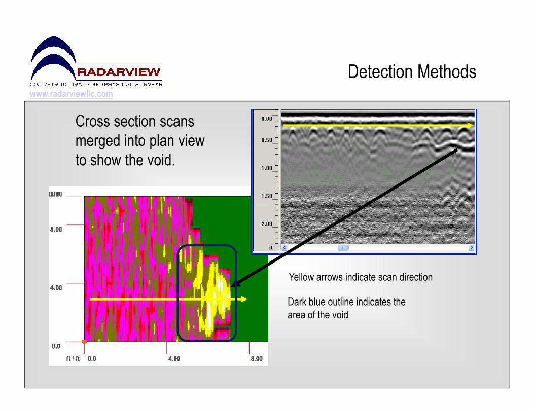
Cross section scans
merged into plan view
to show the void.
Yellow arrows indicate scan direction
Dark blue outline indicates the
area of the void

www.radarviewllc.com
Detection Methods
560’ x 100’ void & elevation survey
Yellow: Offices in the warehouse.
The darker outlines indicate the void area

www.radarviewllc.com
Void Repair Options

www.radarviewllc.com
Void Repair Options
•Urethane Injection
•Grout Injection•Grout Injection
•Mud Jacking

www.radarviewllc.com
Void Repair Options
Visible settlement
www.radarviewllc.com
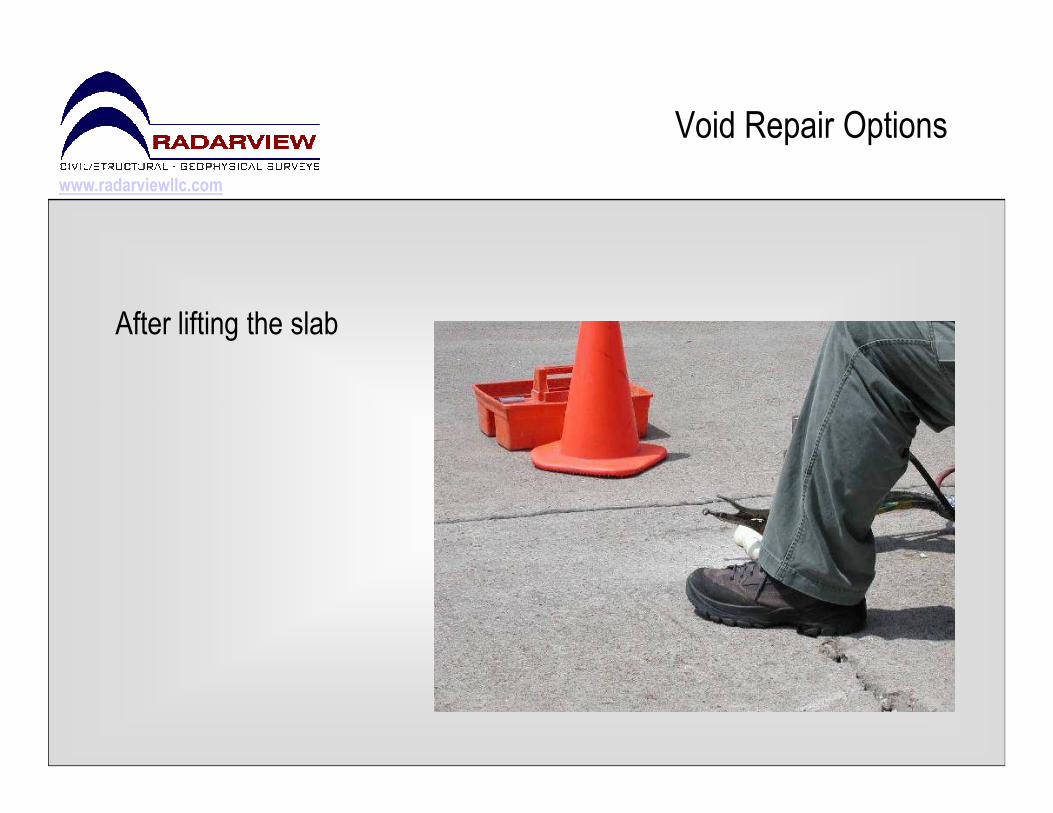
Void Repair Options
After lifting the slab
www.radarviewllc.com
Voids beneath foundation slabs
Residential Void Case StudyResidential Void Case Study
www.radarviewllc.com
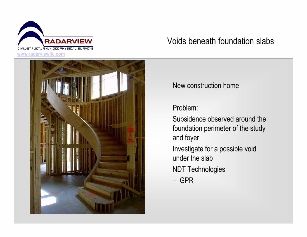
Voids beneath foundation slabs
New construction home
Problem:
Subsidence observed around the Subsidence observed around the
foundation perimeter of the study
and foyer
Investigate for a possible void
under the slab
NDT Technologies
– GPR

www.radarviewllc.com
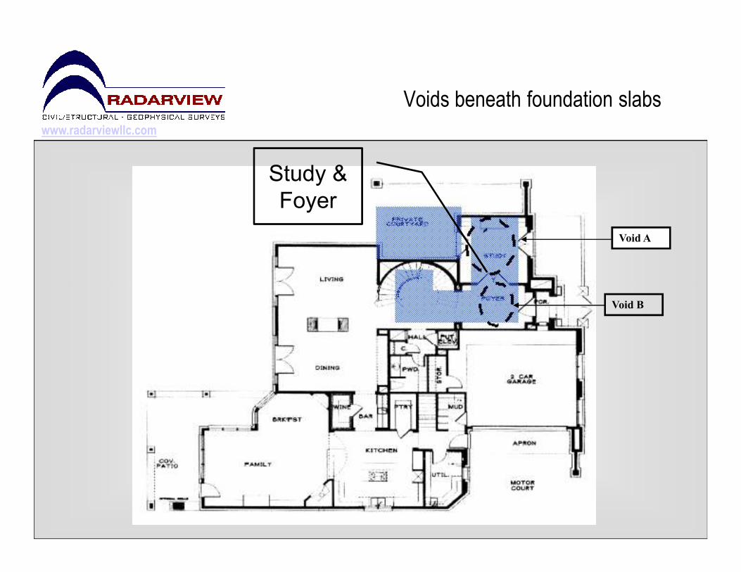
Voids beneath foundation slabs
Study and Foyer were
scanned used a 6” grid
pattern
www.radarviewllc.com
Voids beneath foundation slabs
Void A
Study &
Foyer
Void B

www.radarviewllc.com
Voids beneath foundation slabs
Grade BeamVoids were found in two locations
Geotechnical Engineering Review
Determined the cause to be
poor compaction of fill
A contractor was mobilized to A contractor was mobilized to
pump flowable fill into the voidsVoid B
Void A
www.radarviewllc.com
Voids beneath foundation slabs
Void detection inside a small Void detection inside a small
office/warehouse
www.radarviewllc.com
Voids beneath foundation slabs
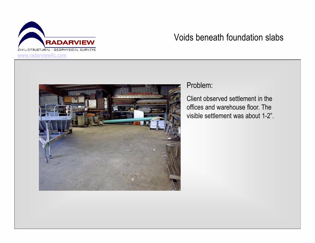
Problem:
Client observed settlement in the
offices and warehouse floor. The
visible settlement was about 1-2”.

www.radarviewllc.com
GYM
Front office
Kitchen &
bathroom
Voids beneath foundation slabs
Problem:
The black outlines indicate the
void locations.
The front office void is detailed
on the following slide.

www.radarviewllc.com
Voids beneath foundation slabs
Front office slab was broken
out to verify the void and
repair utilities.
Voids are evident throughout the scan (2-3” deep).
www.radarviewllc.com
Proposed foundation location for a Proposed foundation location for a
new industrial control room building.

www.radarviewllc.com
Proposed foundation location
The orange paint
outline shows the
area to be examined.
www.radarviewllc.com
Proposed foundation location
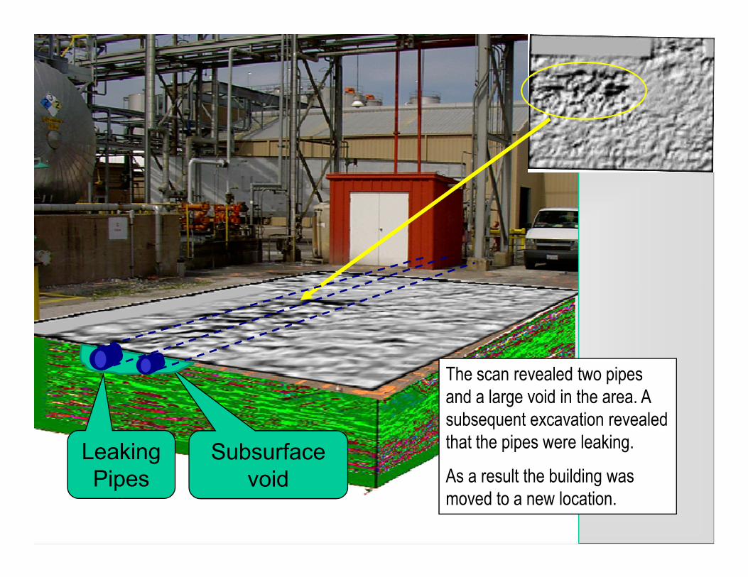
Subsurface
void
Leaking
Pipes
The scan revealed two pipes
and a large void in the area. A
subsequent excavation revealed
that the pipes were leaking.
As a result the building was
moved to a new location.
www.radarviewllc.com
Pavement Evaluation Pavement Evaluation Effects of voids on pavement

www.radarviewllc.com
Pavement Evaluation
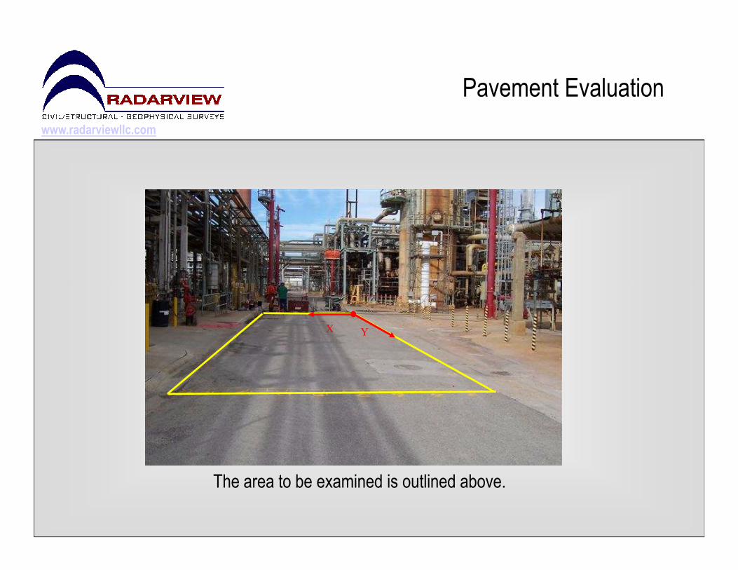
Pavement within an industrial facility

www.radarviewllc.com
Pavement Evaluation
X
Y
The area to be examined is outlined above.
www.radarviewllc.com
Pavement Evaluation
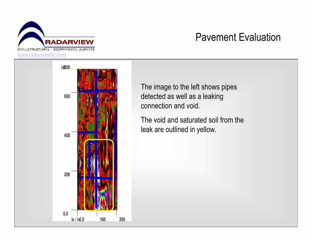
The image to the left shows pipes
detected as well as a leaking
connection and void.
The void and saturated soil from the The void and saturated soil from the
leak are outlined in yellow.
www.radarviewllc.com
Pavement Evaluation
YX
The area to be examined is outlined above.
www.radarviewllc.com
Pavement Evaluation
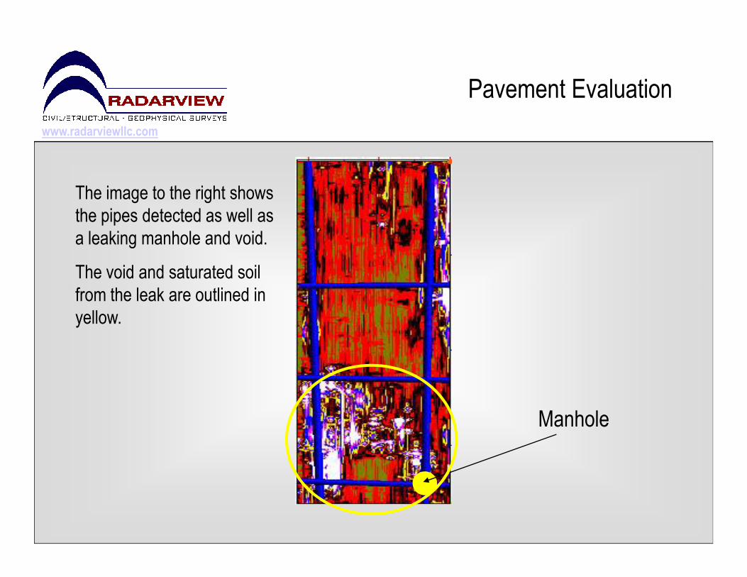
The image to the right shows
the pipes detected as well as
a leaking manhole and void.
The void and saturated soil
from the leak are outlined in
Manhole
from the leak are outlined in
yellow.
www.radarviewllc.com
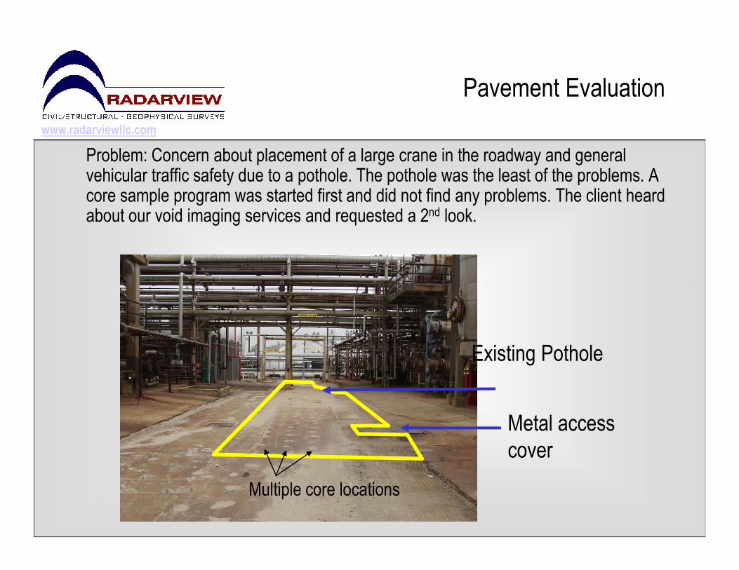
Problem: Concern about placement of a large crane in the roadway and general vehicular traffic safety due to a pothole. The pothole was the least of the problems. A core sample program was started first and did not find any problems. The client heard about our void imaging services and requested a 2nd look.
Pavement Evaluation
Metal access
cover
Existing Pothole
Multiple core locations
www.radarviewllc.com
Pavement Evaluation
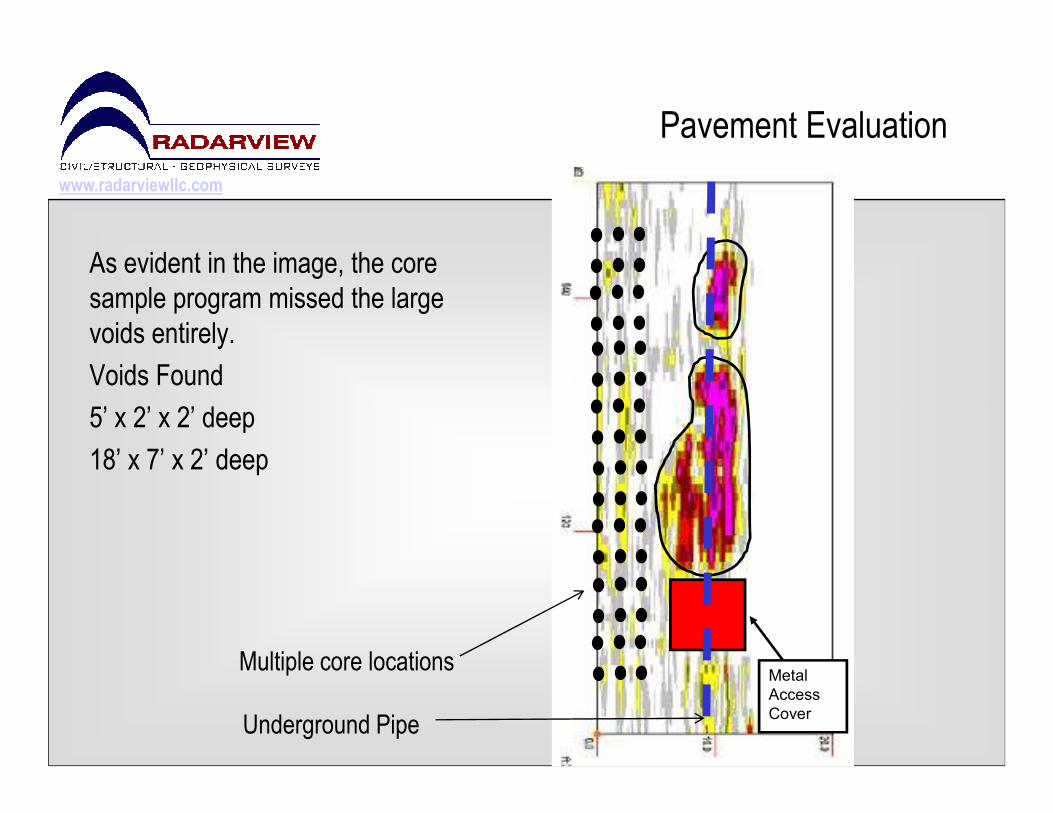
As evident in the image, the core
sample program missed the large
voids entirely.
Voids Found
5’ x 2’ x 2’ deep5’ x 2’ x 2’ deep
18’ x 7’ x 2’ deep
Metal
Access
Cover
Multiple core locations
Underground Pipe

www.radarviewllc.com
Settlement of pavement around storage
Pavement Evaluation
Settlement of pavement around storage
tanks within an industrial facility
www.radarviewllc.com
Pavement Evaluation
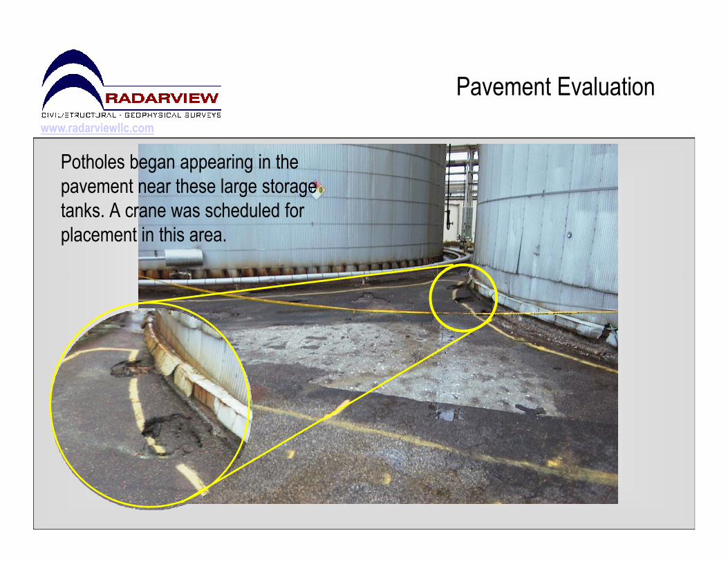
Potholes began appearing in the
pavement near these large storage
tanks. A crane was scheduled for
placement in this area.

www.radarviewllc.com
Sulfur Sulfur
The outline below shows the intermittent void area detected beneath the pavement.
Erosion of soil from a nearby leaking acid cooling tower was the cause.
Pavement Evaluation
Pump
Base
Sulfur
Tank
Sulfur
Tank
Voids

www.radarviewllc.com
Leaking Cooling Unit eroded the soil underneath the pavement and deteriorated the concrete as well.
Pavement Evaluation
www.radarviewllc.com
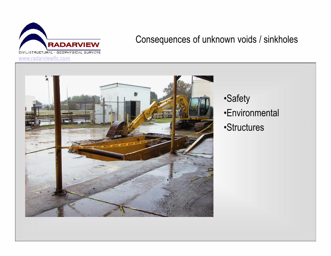
Consequences of unknown voids / sinkholes
•Safety
•Environmental
•Structures•Structures
www.radarviewllc.com
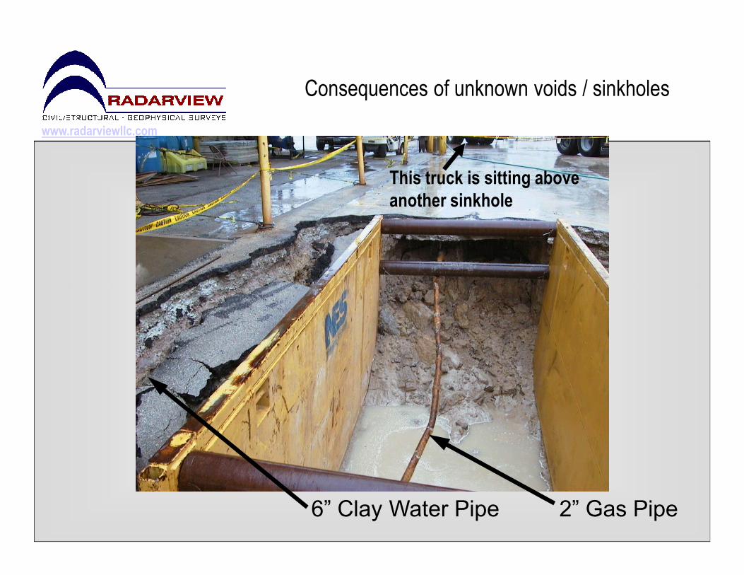
Consequences of unknown voids / sinkholes
This truck is sitting above
another sinkhole
2” Gas Pipe6” Clay Water Pipe

www.radarviewllc.com
Consequences of unknown voids / sinkholes
6” Clay Pipe

www.radarviewllc.com
Consequences of unknown voids / sinkholes
TankTank
Void
The truck that was shown two slides before is outlined below. Another large void was
detected where the truck was parked.
Sump
Tank
www.radarviewllc.com
Wharf Surveys / bulkhead walls
Wharf & bulkhead surveysWharf & bulkhead surveys
www.radarviewllc.com
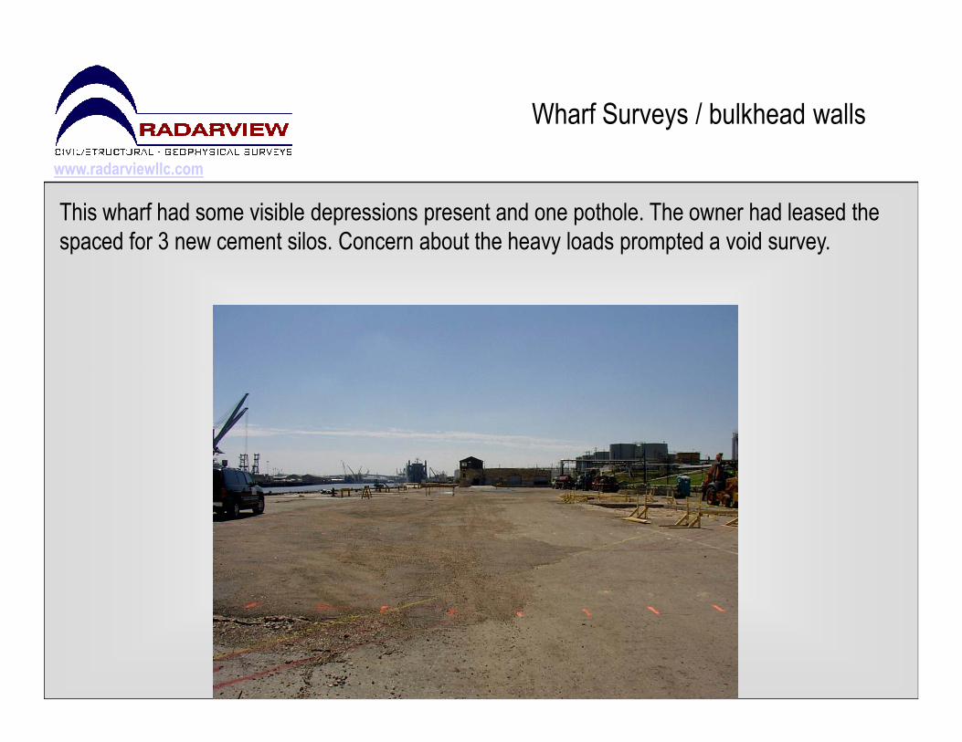
Wharf Surveys / bulkhead walls
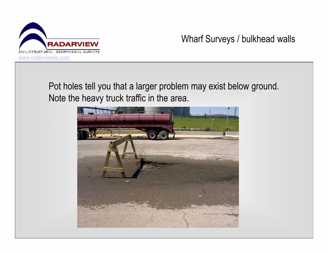
This wharf had some visible depressions present and one pothole. The owner had leased the
spaced for 3 new cement silos. Concern about the heavy loads prompted a void survey.
www.radarviewllc.com
Wharf Surveys / bulkhead walls
Pot holes tell you that a larger problem may exist below ground.
Note the heavy truck traffic in the area.

www.radarviewllc.com
Wharf Surveys / bulkhead walls
Void
There was a void over 100ft x 25 ft in area.
Only the pot hole indicated there was a
problem. 6 months after this survey, a crane
fell through the pavement. The owner had not
repaired the void.

www.radarviewllc.com
Wharf Surveys / bulkhead walls
This concrete bulkhead was examined
for voids – work was performed from a
boat. The area in yellow to the left was
examined and the data image below
shows the void in an elevation view.
Concrete Bulkhead Wall
www.radarviewllc.com
Concrete Thickness
�GPR
�Impact-Echo�Impact-Echo
–ASTM Standard C 1383-98a
www.radarviewllc.com
Concrete Thickness
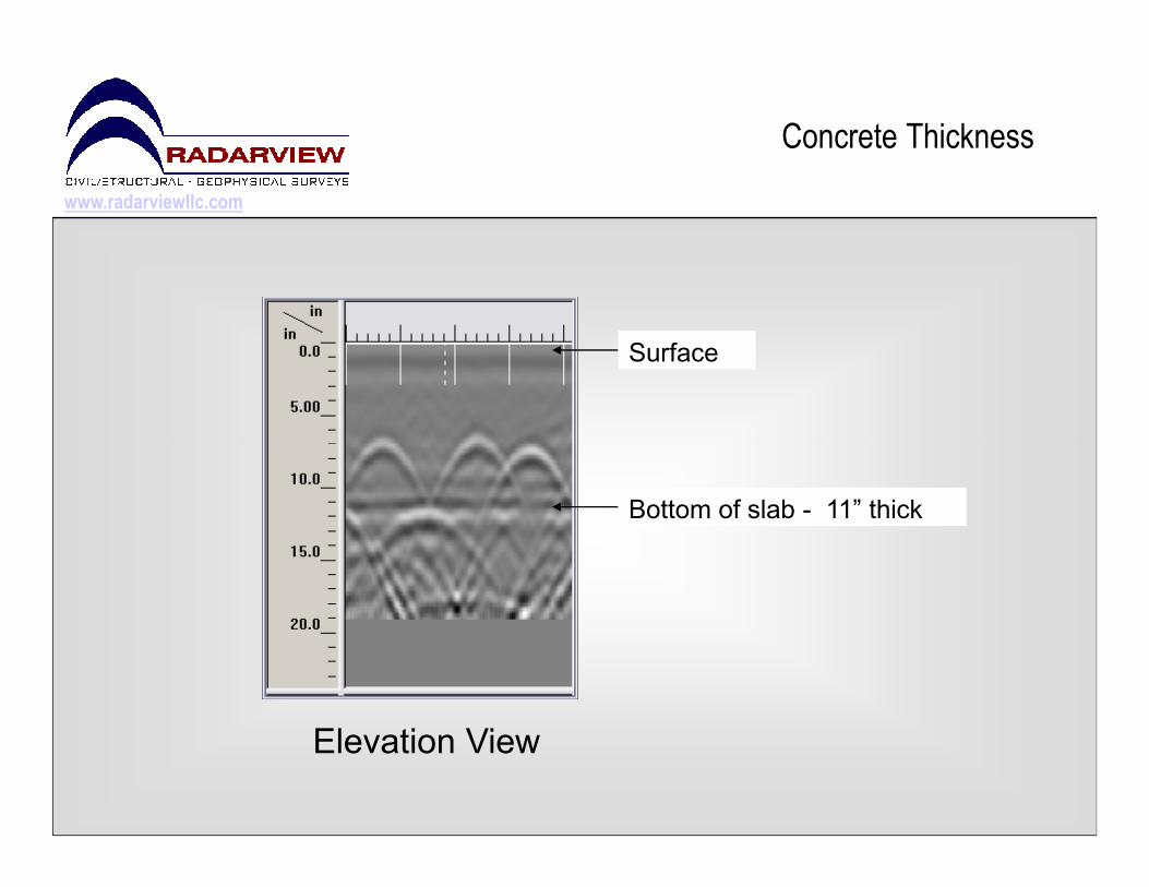
Surface
Elevation View
Bottom of slab - 11” thick
www.radarviewllc.com
Concrete Thickness
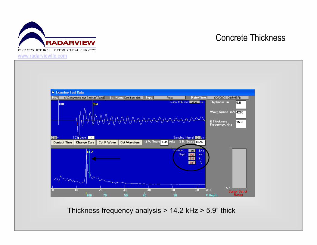
Thickness frequency analysis > 14.2 kHz > 5.9” thick
www.radarviewllc.com
Locating poor consolidation/honeycombs
�Impact-Echo
–ASTM Standard C 1383-98a
www.radarviewllc.com
Locating poor consolidation/honeycombs
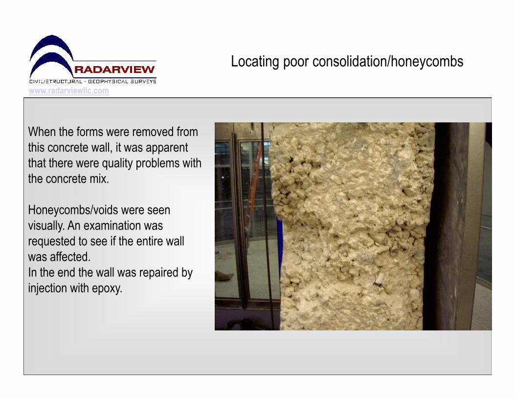
When the forms were removed from
this concrete wall, it was apparent
that there were quality problems with
the concrete mix.
Honeycombs/voids were seen
visually. An examination was
requested to see if the entire wall
was affected.
In the end the wall was repaired by
injection with epoxy.
www.radarviewllc.com
Locating poor consolidation/honeycombs
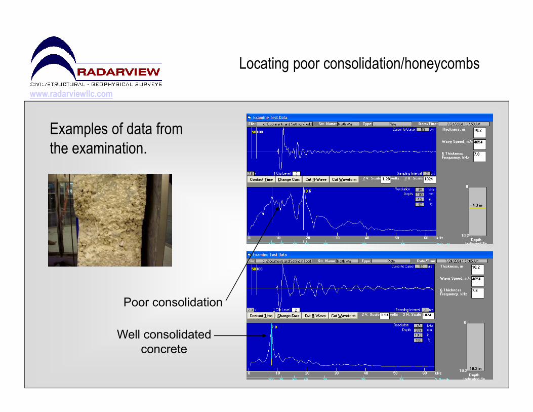
Examples of data from
the examination.
Well consolidated
concrete
Poor consolidation

Availability
800.557.3134
www.radarviewllc.com
Radarview LLC
Nationwide Services