Embed Size (px)
Citation preview
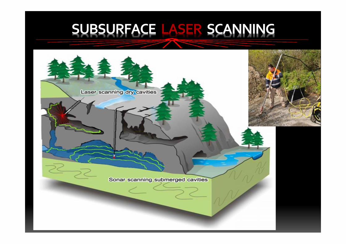
• Subsurface laser scanning andmultibeam sonar void surveys
• What really does lie beneath andwhere exactly?
• Mitigating your Risk
SUBSURFACE LASER SCANNING
SUBSURFACE LASER SCANNING
UNDERGROUND CAVITY SURVEYS
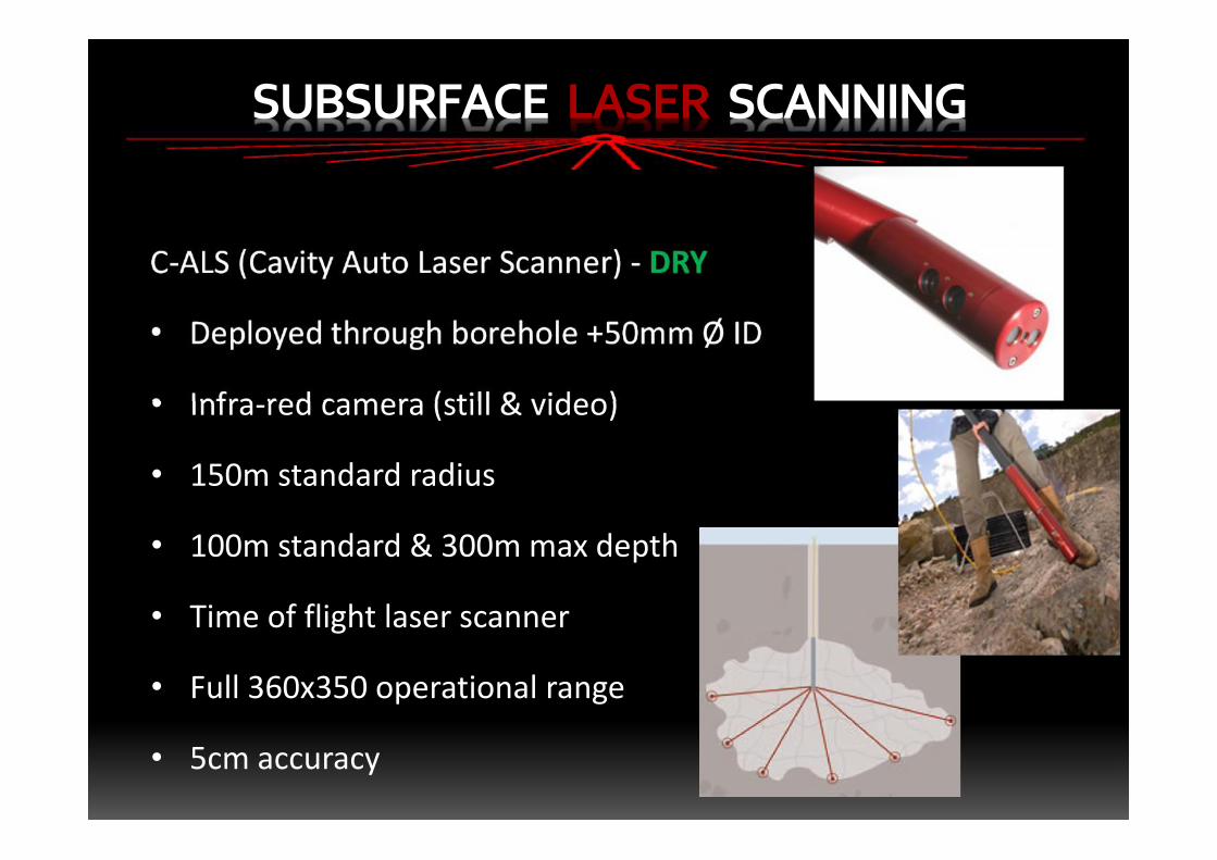
C-ALS (Cavity Auto Laser Scanner) - DRY
• Deployed through borehole +50mm Ø ID
• Infra-red camera (still & video)
• 150m standard radius
• 100m standard & 300m max depth
• Time of flight laser scanner
• Full 360x350 operational range
• 5cm accuracy
SUBSURFACE LASER SCANNING
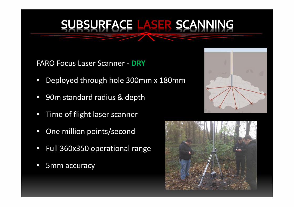
FARO Focus Laser Scanner - DRY
• Deployed through hole 300mm x 180mm
• 90m standard radius & depth
• Time of flight laser scanner
• One million points/second
• Full 360x350 operational range
• 5mm accuracy
SUBSURFACE LASER SCANNING
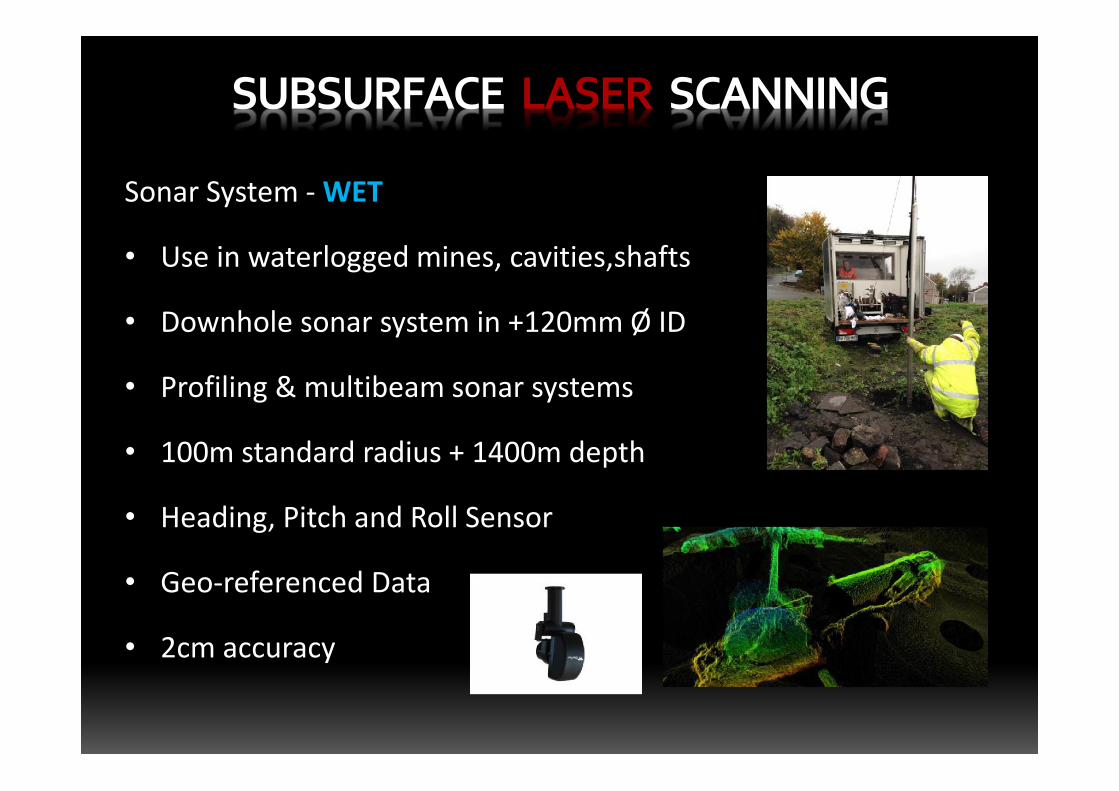
Sonar System -WET
• Use in waterlogged mines, cavities,shafts
• Downhole sonar system in +120mm Ø ID
• Profiling & multibeam sonar systems
• 100m standard radius + 1400m depth
• Heading, Pitch and Roll Sensor
• Geo-referenced Data
• 2cm accuracy
SUBSURFACE LASER SCANNING
SUBSURFACE LASER SCANNING
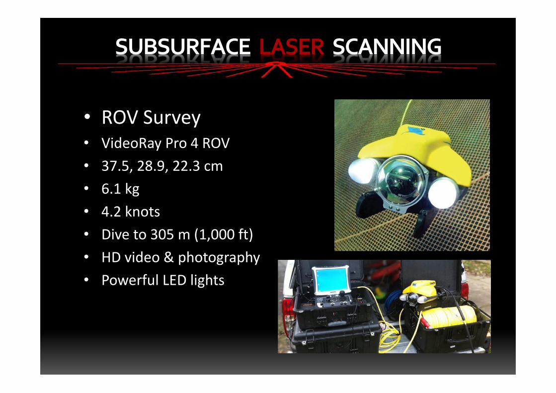
• ROV Survey• VideoRay Pro 4 ROV• 37.5, 28.9, 22.3 cm• 6.1 kg• 4.2 knots• Dive to 305 m (1,000 ft)• HD video & photography• Powerful LED lights
SUBSURFACE LASER SCANNING
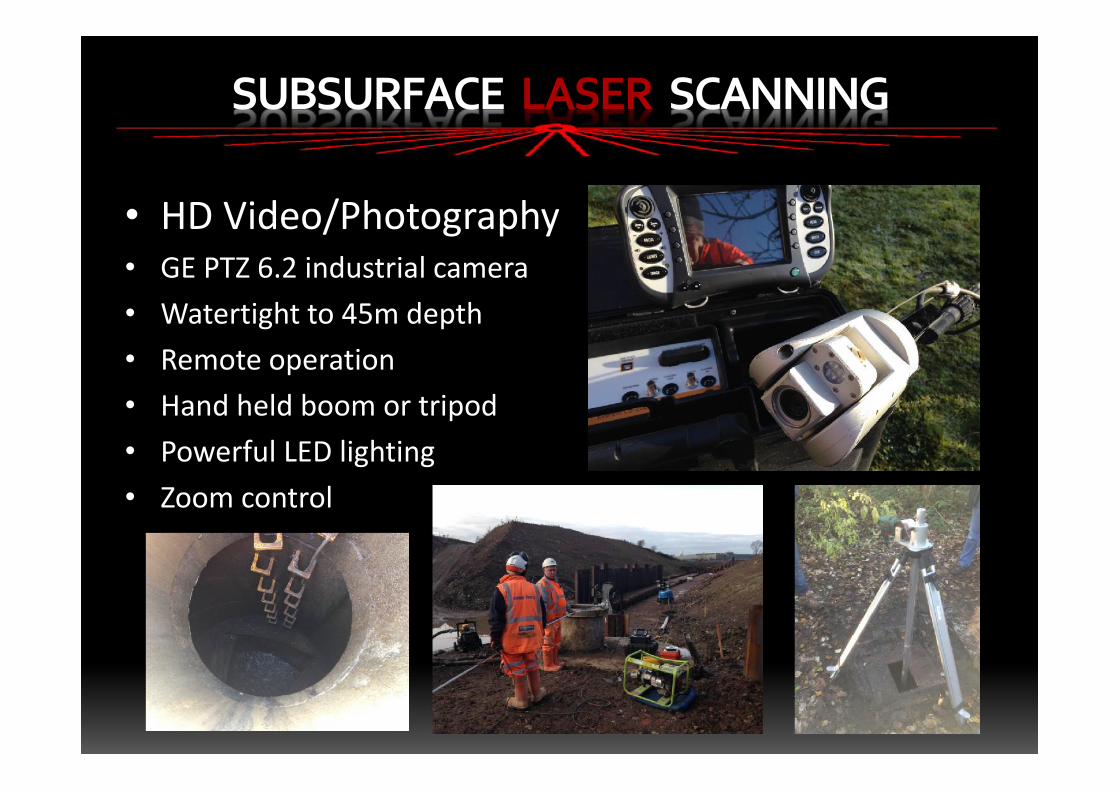
• HD Video/Photography• GE PTZ 6.2 industrial camera• Watertight to 45m depth• Remote operation• Hand held boom or tripod• Powerful LED lighting• Zoom control
SUBSURFACE LASER SCANNING
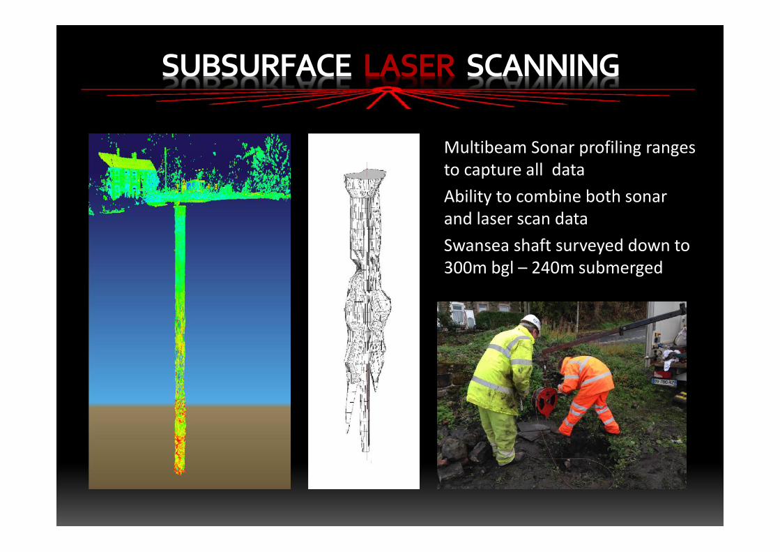
Multibeam Sonar profiling rangesto capture all dataAbility to combine both sonarand laser scan dataSwansea shaft surveyed down to300m bgl – 240m submerged
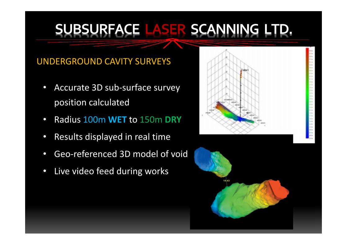
• Accurate 3D sub-surface surveyposition calculated
• Radius 100mWET to 150m DRY
• Results displayed in real time
• Geo-referenced 3D model of void
• Live video feed during works
SUBSURFACE LASER SCANNING LTD.
UNDERGROUND CAVITY SURVEYS
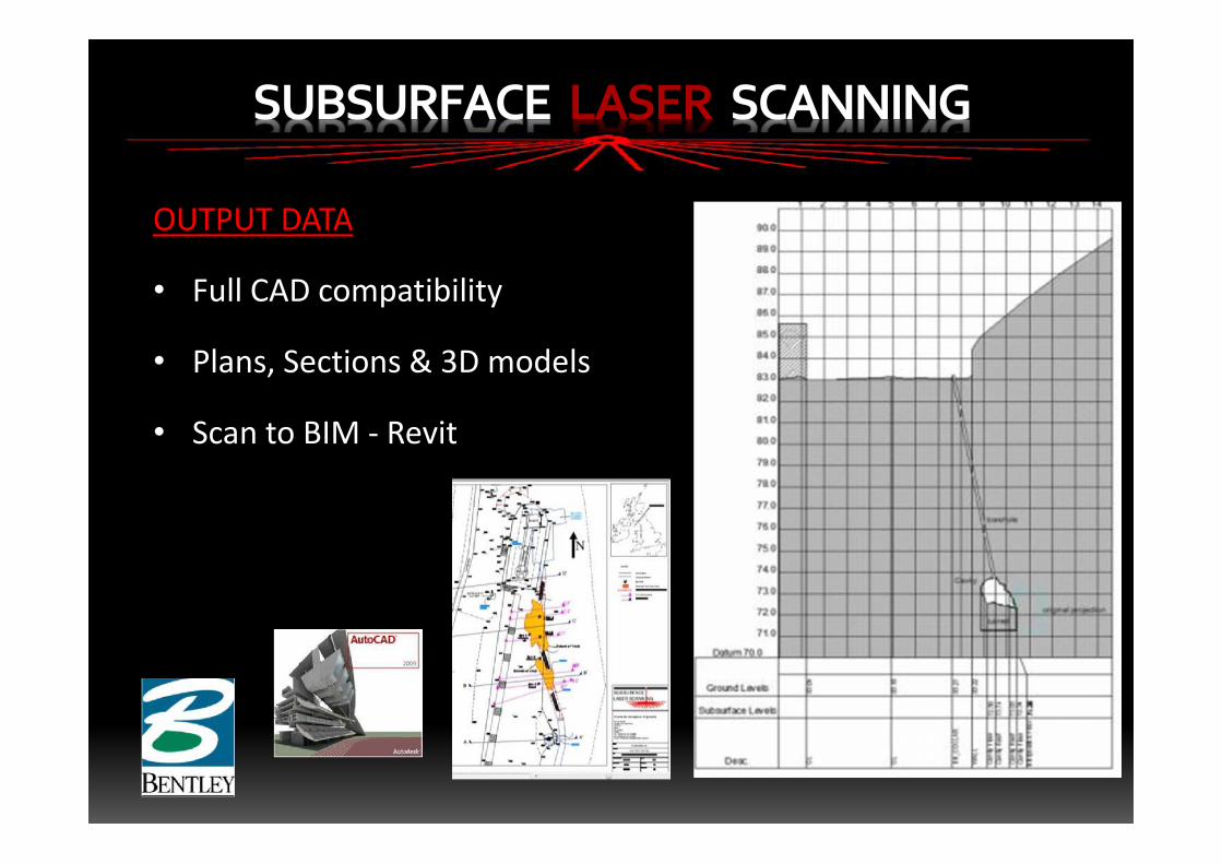
OUTPUT DATA
• Full CAD compatibility
• Plans, Sections & 3D models
• Scan to BIM - Revit
SUBSURFACE LASER SCANNING
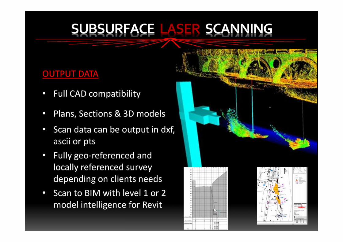
OUTPUT DATA
• Full CAD compatibility
• Plans, Sections & 3D models
• Scan data can be output in dxf,ascii or pts
• Fully geo-referenced andlocally referenced surveydepending on clients needs
• Scan to BIM with level 1 or 2model intelligence for Revit
SUBSURFACE LASER SCANNING
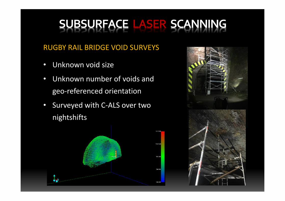
• Unknown void size
• Unknown number of voids andgeo-referenced orientation
• Surveyed with C-ALS over twonightshifts
SUBSURFACE LASER SCANNING
RUGBY RAIL BRIDGE VOID SURVEYS
SUBSURFACE LASER SCANNING
Case Study
Subsurface Laser Scan survey
Metaliferous mine voidDrump Road, Redruth, Cornwall
• Void encountered whilst drilling borehole on land adjacent to
Penzance to London main railway line
• CCTV camera used unable to ascertain size, shape or orientation
• Possibility of railway line and adjacent buildings undermining
• Requested to carry out subsurface laser scan survey to produce
a 3D geo-referenced model of the surface and underground void
SUBSURFACE LASER SCANNING
SUBSURFACE LASER SCANNING
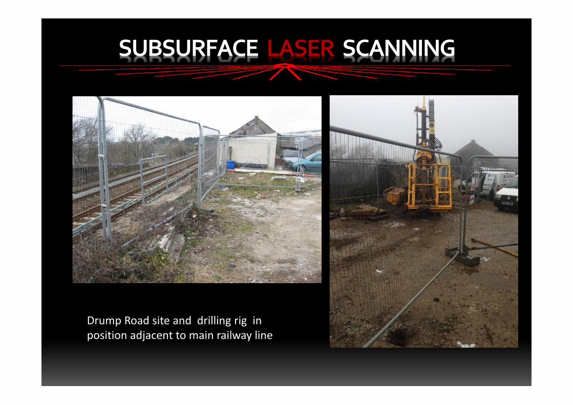
Drump Road site and drilling rig inposition adjacent to main railway line
SUBSURFACE LASER SCANNING
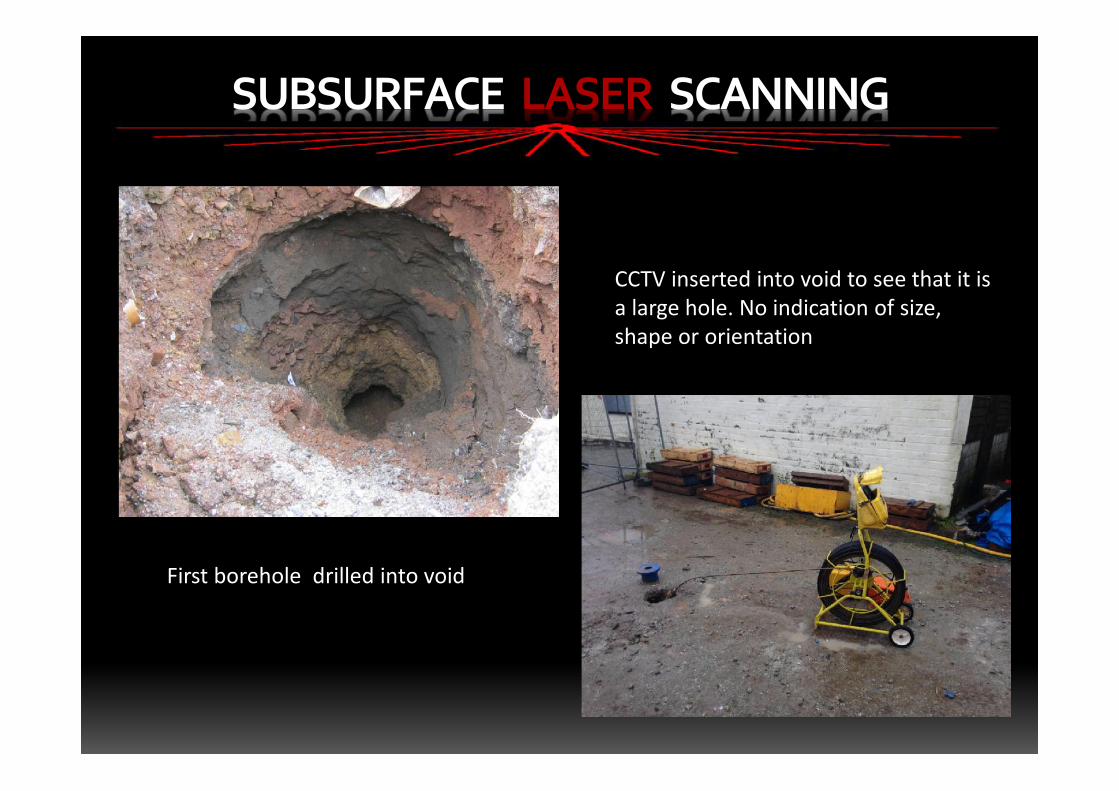
First borehole drilled into void
CCTV inserted into void to see that it isa large hole. No indication of size,shape or orientation
SUBSURFACE LASER SCANNING
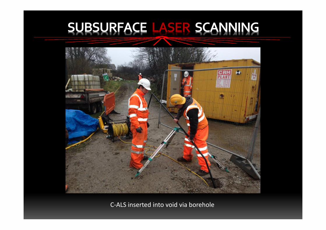
C-ALS inserted into void via borehole
SUBSURFACE LASER SCANNING
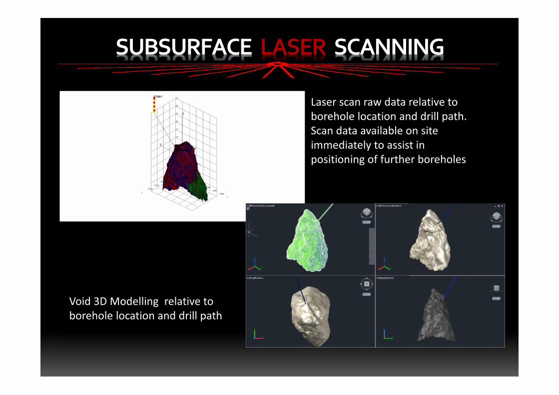
Laser scan raw data relative toborehole location and drill path.Scan data available on siteimmediately to assist inpositioning of further boreholes
Void 3D Modelling relative toborehole location and drill path
SUBSURFACE LASER SCANNING
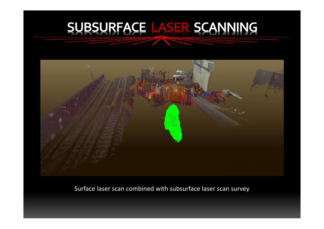
Surface laser scan combined with subsurface laser scan survey
FINAL DELIVERABLES
• Combined 3D geo-referenced void and surface laser scan
• Confirmation that void does not undermine the main railway
line or buildings, although large adjacent shaft is known
• Confirmation that there were no attached adits or tunnels
• Accurate volume calculated for backfilling
• Pre-works prior to new track slab install over shaft
SUBSURFACE LASER SCANNING
SUBSURFACE LASER SCANNING
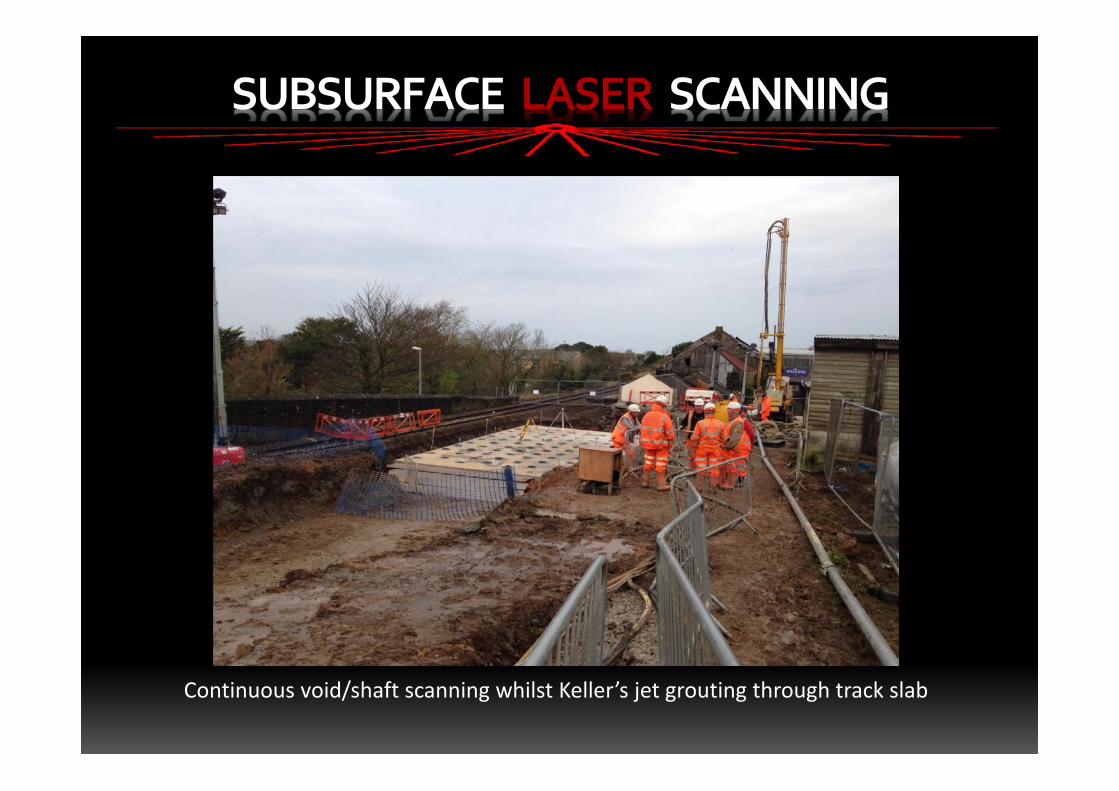
Continuous void/shaft scanning whilst Keller’s jet grouting through track slab
SUBSURFACE LASER SCANNING
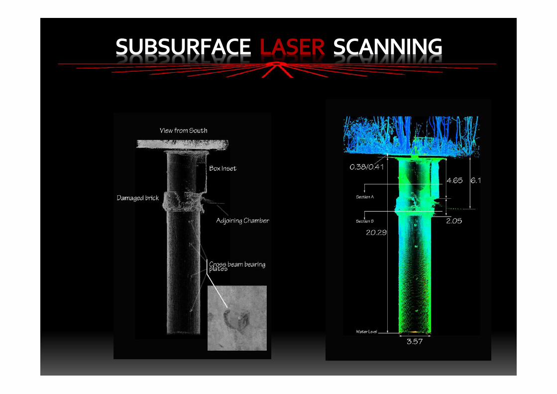
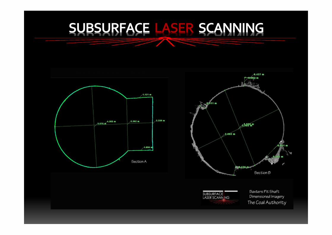
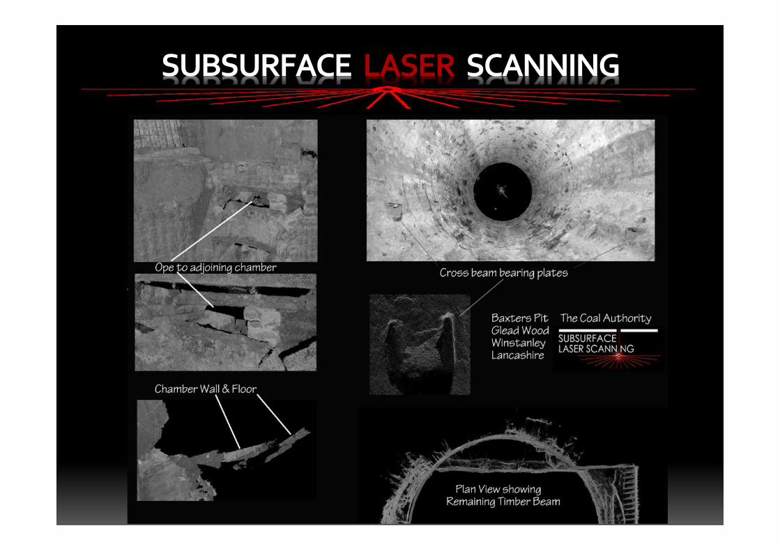
Case Study
Subsurface Laser Scan Survey
Collins Green Pit ShaftWigan, Lancashire
• Geoterra contacted by The Coal Authority in June 2015
• Collins Green old mine shaft
• Capped in 1930’s
• Suspected collapsing of shaft lining
• Previously used a CCTV for inspection
• Requested to carry out laser scan survey to produce a full 3D geo-
referenced model
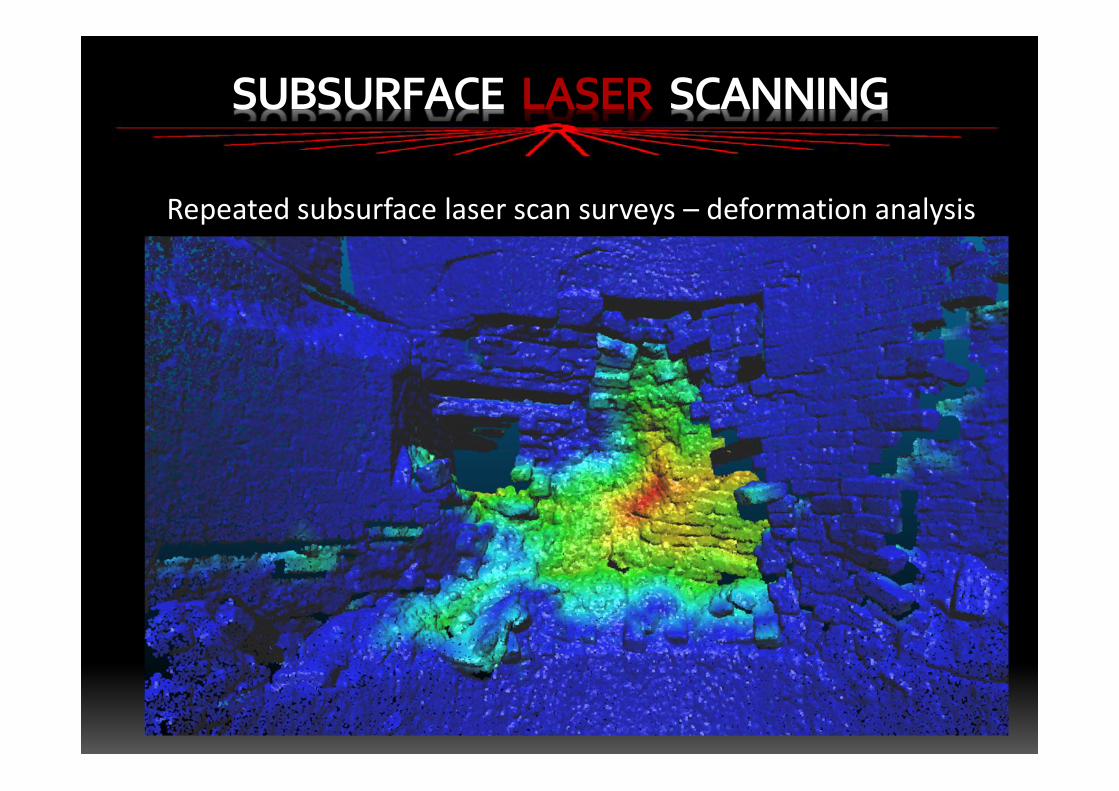
• Re-surveyed in June 2016 to determine any lining deformation
SUBSURFACE LASER SCANNING
SUBSURFACE LASER SCANNING
SUBSURFACE LASER SCANNING
SUBSURFACE LASER SCANNING
SUBSURFACE LASER SCANNING
SUBSURFACE LASER SCANNING
Repeated subsurface laser scan surveys – deformation analysis
SUBSURFACE LASER SCANNING
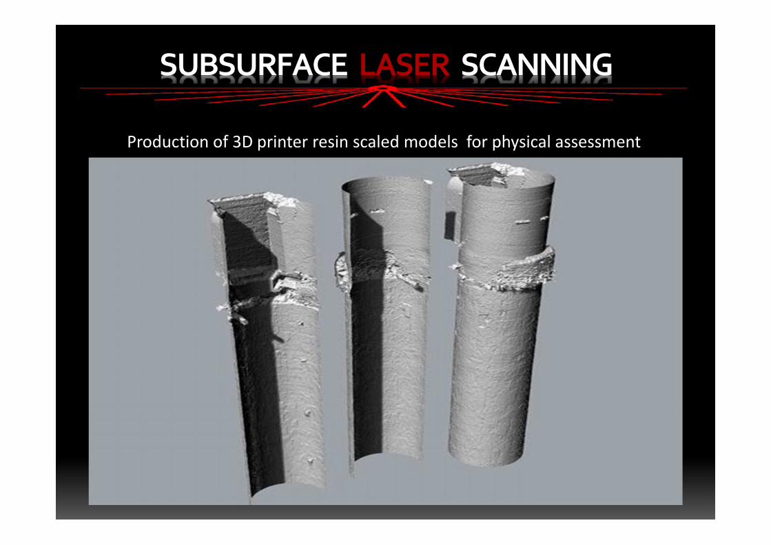
Production of 3D printer resin scaled models for physical assessment
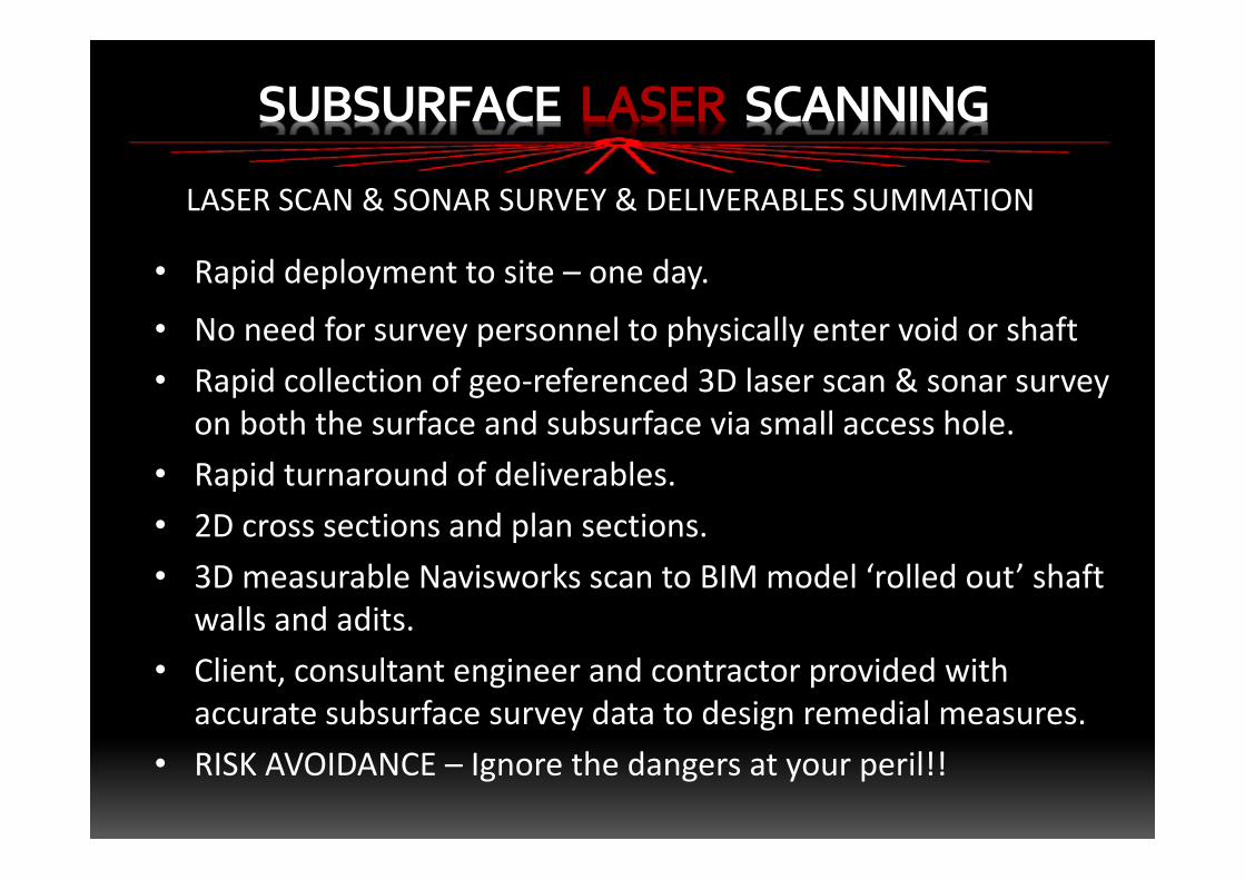
LASER SCAN & SONAR SURVEY & DELIVERABLES SUMMATION
• Rapid deployment to site – one day.
• No need for survey personnel to physically enter void or shaft• Rapid collection of geo-referenced 3D laser scan & sonar survey
on both the surface and subsurface via small access hole.• Rapid turnaround of deliverables.• 2D cross sections and plan sections.• 3D measurable Navisworks scan to BIM model ‘rolled out’ shaft
walls and adits.• Client, consultant engineer and contractor provided with
accurate subsurface survey data to design remedial measures.• RISK AVOIDANCE – Ignore the dangers at your peril!!
SUBSURFACE LASER SCANNING
SUBSURFACE LASER SCANNING
Thank you for listening
Any Questions?