Embed Size (px)
Citation preview

Shell Exploration and Production Company UK 1May 2011
Subsurface Enablement : Brent Well Abandonments
DEVEX – The Production &
Development Conference
11th -12th May 2011
Gerry Moorhouse
Production Technologist
Shell Aberdeen
Many thanks to: Reservoir Engineering, Geology and
Petrophysics colleagues: Claire Woods, Dave Sharpe, Chris
Bugg, Eduardo Delgado and the many people who have
contributed.

Shell U.K. Ltd
CAUTIONARY STATEMENT
This presentation contains forward-looking statements concerning the financial condition, results of operations and businesses of Royal Dutch Shell. All statements other than statements of historical fact are, or may be deemed to be, forward-looking statements. Forward-looking statements are statements of future expectations that are based on management’s current expectations and assumptions and involve known and unknown risks and uncertainties that could cause actual results, performance or events to differ materially from those expressed or implied in these statements. Forward-looking statements include, among other things, statements concerning the potential exposure of Royal Dutch Shell to market risks and statements expressing management’s expectations, beliefs, estimates, forecasts, projections and assumptions. These forward-looking statements are identified by their use of terms and phrases such as ‘‘anticipate’’, ‘‘believe’’, ‘‘could’’, ‘‘estimate’’, ‘‘expect’’, ‘‘intend’’, ‘‘may’’, ‘‘plan’’, ‘‘objectives’’, ‘‘outlook’’, ‘‘probably’’, ‘‘project’’, ‘‘will’’, ‘‘seek’’, ‘‘target’’, ‘‘risks’’, ‘‘goals’’, ‘‘should’’ and similar terms and phrases. Also included as a forward looking statement is our disclosure of reserves, proved oil and gas reserves, proven mining reserves, organic reserves, net reserves and resources. There are a number of factors that could affect the future operations of Royal Dutch Shell and could cause those results to differ materially from those expressed in the forward-looking statements included in this presentation, including (without limitation): (a) price fluctuations in crude oil and natural gas; (b) changes in demand for the Group’s products; (c) currency fluctuations; (d) drilling and production results; (e) reserve estimates; (f) loss of market and industry competition; (g) environmental and physical risks; (h) risks associated with the identification of suitable potential acquisition properties and targets, and successful negotiation and completion of such transactions; (I) the risk of doing business in developing countries and countries subject to international sanctions; (j) legislative, fiscal and regulatory developments including potential litigation and regulatory effects arising from recategorisation of reserves; (k) economic and financial market conditions in various countries and regions; (l) political risks, including the risks of expropriation and renegotiation of the terms of contracts with governmental entities, delays or advancements in the approval of projects and delays in the reimbursement for shared costs; and (m) changes in trading conditions. All forward-looking statements contained in this presentation are expressly qualified in their entirety by the cautionary statements contained or referred to in this section. Readers should not place undue reliance on forward-looking statements. Additional factors that may affect future results are contained in Royal Dutch Shell’s 20-F for the year ended December 31, 2010 (available at www.shell.com/investor and www.sec.gov ). These factors also should be considered by the reader.Each forward-looking statement speaks only as of 12th May, 2011. Neither Royal Dutch Shell nor any of its subsidiaries undertake any obligation to publicly update or revise any forward-looking statement as a result of new information, future events or other information. In light of these risks, results could differ materially from those stated, implied or inferred from the forward-looking statements contained in this presentation.
The United States Securities and Exchange Commission (SEC) permits oil and gas companies, in their filings with the SEC, to disclose only proved reserves that a company has demonstrated by actual production or conclusive formation tests to be economically and legally producible under existing economic and operating conditions. We use certain terms in this presentation that SEC's guidelines strictly prohibit us from including in filings with the SEC. U.S. Investors are urged to consider closely the disclosure in our Form 20-F, File No 1-32575, available on the SEC website www.sec.gov. You can also obtain these forms from the SEC by calling 1-800-SEC-0330.
2March 2011

Well Abandonment
“That’s Just for Well Engineering”

Outline of Presentation
4
Well Abandonments: UK Governance & Geological
Interpretation
Reservoir Pressurisation: Dealing with Previous Sidetracks
and Well Abandonment Legacy
Cement Logging and Petrophysics: Beyond CBLs
Summary of Subsurface Contribution: Framework for
Abandonments

UK Legislation is Goal Setting, does not prescribe
methodology
UK Oil & Gas Publish “Guidelines for the Suspension and
Abandonment of Wells” . These include “rules” but in general
are based on a rational approach to abandonments including
implementation of “rock to rock” barriers and restoration of
“caprocks”.
UK W. A. Governance
1
5

Copyright of Shell UK Exploration and Production 6May 2011
Isolations required
between distinct
permeable zones and
surface
Distinction between
hydrocarbon bearing,
pressure regime,
water bearing
Geology &
Petrophysics provide
interpretation. Each
field will be different
UK Oil and Gas Guidelines - Distinct Permeable Zones

Copyright of Shell UK Exploration and Production 7May 2011
Understand origin and migration
path of any hydrocarbons
sampled
Wellbore investigations e.g.
cased hole logging to identify
hydrocarbons in permeable
formations
Permeable Zones Hydrocarbon Bearing?
δδδδD (0/00) Methaneversus
δδδδC13(0/00) Methane

What can be assumed? Is a simple approach necessarily
conservative? What are the benefits of a rational approach
that honours field and basin data, geology?
Reservoir Repressurisation
2

Copyright of Shell UK Exploration and Production 9May 2011
Objectives
� Have an understanding both of the likely range of eventual
recharge pressures and timescales over which this will occur
�Understand the ability of shallower shales to act as barriers to
flow - strength versus depth and time
�Use better annular cement (or squeezing shale) further away
from perforations – prove by cement logging
Risks
�Current reservoir state provides no guarantee that observations
today (eg no leaks or pressure build up) provide a reliable future
prediction
�Uncertainties in Material Balance
Objectives of Reservoir Recharging Study

Copyright of Shell UK Exploration and Production 10May 2011
Geology
�Estimate size of Brent regional aquifer
�Identify potential recharge paths
Reservoir Engineering
�Build dynamic model for range of aquifer geometries, sizes
and properties
�History match model and discard scenarios that were
inconsistent with production and pressure data for Brent
and surrounding fields
�Assess range of recharge rates and pressures with
remaining models
Workflow

Copyright of Shell UK Exploration and Production 11May 2011
Low aquifer:
�No indication of
communication between Brent
and Statfjord fields
�Fault throws along western
and eastern boundaries
greater than Brent reservoir
thickness
High aquifer:
�All fields with similar
overpressure (approx 25 bar)
share common aquifer
Brent Regional aquifer size range

Copyright of Shell UK Exploration and Production 12May 2011
High volume aquifer attached to entire western side of model (poor history match)
Infinite aquifer attached to western side of model excluding Dunlin field
High volume attached to western side of model excluding Dunlin field, reduced compressibility
Recharging rates and uncertainty range
High volume
aquifer attached to
entire western side
of model failed to
honour Dunlin field
pressure data,
therefore set upper
limit to aquifer
connectivity

Copyright of Shell UK Exploration and Production 13May 2011
Well Abandonment
today includes the
full legacy of
development
drilling and
previous
abandonments for
slot recovery
Reduce Risks from Previous Sidetrack Activity

Copyright of Shell UK Exploration and Production 14May 2011
Some of the previous
slot recovery isolations
are higher risk than what
we would currently aim
to achieve
It is almost impossible to
re-enter wellbores after
sidetracks have been
completed
A mitigation is to
complete a barrier at a
shallower depth
How to Reduce Risks from Previous Sidetrack Activity
Utsira Shale
layers
Frigg -Skade permeable formations
Horda Shales
Balder sands
Shetland Shales
Reservoir
Brent

Rock to rock barriers require that the integrity of the seal
between casing and formation (usually assumed to be
primary annular cement) be known and that its ability to
provide hydraulic isolation be assured. Cement logs can
provide basis to assess annular isolation.
Cement Logging and Petrophysics
3

Shell U.K. Ltd
DETECTING GAS IN OVER-BURDEN FORMATIONS
Logging Conditions:•Challenging!•Expected Low Gas Saturation.•Large casings•Dual Casing strings (or pull casing)•Pulsed Neutron Log
Logging Conditions:•Challenging!•Expected Low Gas Saturation.•Large casings•Dual Casing strings (or pull casing)•Pulsed Neutron Log
• Pulsed Neutron Logs identified Gas at Low Saturations – complemented wellbore observations
Min ID Formation AHDBDFTVDBDF
(in) Top (ft) (ft)
DFE
WHD-Susp flange with 2 x 4" valves. Tested to 500psi
MR220 - mid element (TOF = 104ft) (P/T 500psi)
MSL
Sea
Top of solids behind 13 ⅜" casing (CBL 30/01/2010)
Seabed
643 643
Possible high 20" TTOC
20" TTOC
30" Shoe
HUTTON
9 ⅝" suspension string Formation
13 ⅜" High TTOC , rathole ignored, hole in gauge
20" Shoe
Utsira sst 4 2,017 1,996
Utsira shale 4 2,184 2,157
Utsira sst 3 2,285 2,253
Utsira shale 3 2,466 2,423
Utsira sst 2 2,621 2,566
Utsira shale 2 2,716 2,653
13 3/8" TTOC
Utsira sst 1 3,018 2,913
Utsira shale 1 3,102 2,981
Skade sst 3,564 3,319
13 ⅜" casing x/o 72# to 68#
Frigg sst 4,661 4,025
5,897 4,780
TTOC
TOC - tagged / 10klbs & tested / 2200psi) HORDA
Shale
13⅜" HMN plug at 7066ft (tagged / 5k)
9 ⅝" casing cut at 7,090 ft
BALDER 7,215 5,558
LISTA Fm 7,648 5,813
13 ⅜" top of window Maureen Fm 8,178 6,135
Top 7" PBR
8,582 6,387
9 ⅝" top of window
SHETLAND
GROUP
TTOC 7" Liner
TOC - tagged with 10klbs on 16.0ppg cement
plug 7" HMN bridge plug 14004ft (P/T 500psi)
X-Unconf.
3.920 Top of PBR / Anchor (PBR sheared) Kimmeridge 14,231 9,195
3.920 Halliburton MHR Production Packer 14,277 9,227
BRENT
GROUP
HX4 PES plug (c/w prong/catcher top14293ft )
WEG DUNLIN GROUP14,299 9,242
14,588 9,435
4 1/2" Top of Liner Hanger
Hanger slips 4 1/2"
7" Shoe
STATFJORD
Possible TOC at loss zone FORMATION
4 1/2" Liner Shoe
C C
DESCRIPTIONCURRENT WELL STATUS
918 ft
combined

Shell U.K. Ltd
CBL Feb 2010CBL Feb 2010USIT Feb 2010USIT Feb 2010
CBL Nov 1981CBL Nov 1981
13 3/8’ casing Shoe @ X960 ft AHBDF
IDENTIFY SQUEEZING SHALES

Summary of Subsurface Contribution
to Successful Well Abandonments
5

Copyright of Shell UK Exploration and Production 19May 2011
Provide the framework for well
abandonments:
� Identify reservoir recharging Use as a basis to evaluate the vertical
extent of the “caprock” that provides a
viable seal with sufficient strength
Address legacy abandonment issues
� Identify permeable zones
that represent a risk of lateral
communication between wells –
investigate for presence of
hydrocarbons
Subsurface Contribution Summary
Copyright of Shell UK Exploration and Production 20May 2011
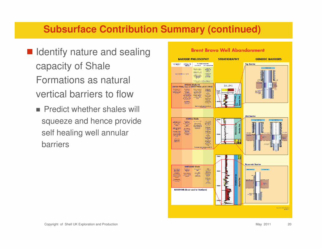
Identify nature and sealing
capacity of Shale
Formations as natural
vertical barriers to flow
� Predict whether shales will
squeeze and hence provide
self healing well annular
barriers
Subsurface Contribution Summary (continued)

Copyright of Shell UK Exploration and Production 21May 2011
Improve current well designs wrt eventual
abandonments
�Explicitly consider and incorporate into well planning
documents the basis of the future abandonment
�Do not overly simplify the nature of the over-burden
Impact of operations and well activities, in particular
sidetracking on eventual abandonments
�Slot recovery should be considered the same as
permanent well abandonment as opportunity to rectify
is very limited
Integrated Approach - Not Just for Well Engineering
Lessons Learnt

Q & A


Fault between Brent and
Statfjord fields is proven
to be sealing against
differential pressures of
4000 psi
Most likely ingress routes
are along the western
edge, south of the Dunlin
field and between the
Hutton and Ninian fields,
where the throw on the
major bounding fault is
smallest
Notes 1 Brent aquifer potential recharge paths

DEVEX - The Production and Development Conference 11th -12th May 2011
Subsurface Enablement : Brent Well Abandonments
G Moorhouse E Delgado C Woods C Bugg
Shell Exploration and Production UK
Abstract
Complications identified in early well abandonments forced a re-think away from individual well by well abandonment
design to a system wide view dictated by the geology of the over-burden. Oil and Gas Guidelines for Well
Abandonments specify that distinct permeable zones are to be isolated from each other and from the surface. For
Brent, the over-burden geology has been assessed and lumped into major distinct permeable zones, including those
that provide the possibility of cross-flow between wellbores and sealing shales. Restoring the integrity of upper
“caprocks” across multiple wellbores is challenging but provides better assurance on a systematic basis that well
abandonments will be successful. A critical tool deployed as part of the well abandonments and which has been
instrumental in providing data to shape the evolution of the abandonment philosophy has been cement bond logging.
As well as the historic role of providing data as to the integrity of the annular cement, the use of Ultrasonic bond
logging tools and Gamma provides valuable formation data. For Brent, this has improved the understanding of the
nature and location of sealing shales as caprocks. An upside is that squeezing shales have been identified and
verified and which provide robust annular isolations. A significant part of the Brent Well Abandonment Philosophy has
been the comprehensive assessment of reservoir recharging. This has resulted in better appreciation of the value of
multiple caprocks in the overall well abandonment philosophy. Improved value of well abandonments can follow from
the Philosophy.
Presentation Abstract