Embed Size (px)
Citation preview
SOUTHWIRE cOmpany
SUbSTaTIOn cablEInSTallaTIOn gUIdE

Southwire Company One Southwire Drive Carrollton, Georgia 30119
© 2013 Southwire Company. All rights reserved. Printed in the United States of America.
Hypalon is a registered trademark of E.I. DuPont DeNemours & Company. National Electrical Code and NEC are registered trademarks of the National Fire Protection Association. Southwire, Southwire Solutions-Energize, and Solonon are registered trademarks of Southwire Company.
This publication is a collection of items of general information related to the subject of substation cable. It is not intended to be nor should it be used as authority for design, construction, or use of substation cable. The design, construction, and use of substation cable should only be undertaken by competent professionals in light of currently accepted design and engineering practices.
While great care has been employed to ensure that the tables and formulas contained herein are free of errors, absolutely no warranties, either expressed or implied, are made as to the accuracy or completeness of any such tables and formulas contained herein.
Those preparing and/or contributing to this publication specifically disclaim any warranty of any kind, either expressed or implied. The warranties of merchantability and fitness for a particular purpose are hereby specifically disclaimed by Southwire and all other parties involved in the creation, production, or delivery of this publication.
Neither Southwire nor anyone else who has been involved in the creation, production, or delivery of this publication shall be liable for any direct, indirect, consequential, or incidental damages arising out of the use, the results of the use, or inability to use such publication, even if Southwire has been advised of the possibility of such damages or claim. Some states do not allow the exclusion or limitation for consequential incidental damages, so the above limitation may not apply to you.

SOUTHWIrE COmPANy’S SUbSTATION CAblE INSTAllATION GUIDE PrOvIDES INSTAllATION INFOrmATION FOr ExTrUDED DIElECTrIC SUbSTATION CAblE SySTEmS. THIS GUIDE COvErS COPPEr AND AlUmINUm CONDUCTOrS FrOm 14 AWG THrOUGH 1000 kCmIl, INSUlATED FOr OPErATION FrOm 600 vOlTS THrOUGH 2 kIlOvOlTS. AlTHOUGH THIS GUIDE INClUDES SPECIFIC rECOmmENDATIONS, IT IS ImPOSSIblE TO COvEr All POSSIblE DESIGN, INSTAllATION, AND OPErATING SITUATIONS FOr EvEry APPlICATION. plEaSE USE THE InfORmaTIOn In THIS gUIdE aS gEnERal gUIdElInES Only. THIS gUIdE IS InTEndEd fOR USERS WHO HavE an UndERSTandIng Of THE EngInEERIng fUndamEnTalS Of SUbSTaTIOn cablE SySTEmS.
USIng THIS gUIdE
SUbSTATION CAblE INSTAllATION GUIDE
This guide includes many tables, equations, and related data for the convenience of the user. Southwire’s comprehensive Product Catalog provides additional data on cable weights, dimensions, and specifications to be used in concert with this guide. This and other information can be found at www.southwire.com.
This guide is not a complete representation of the full range of wire and cable products offered by Southwire. For information on any of your wire and cable needs, please contact your local Southwire representative.
We welcome your suggestions so that we can make future editions more relevant, more current, and easier to use.

4
TablE Of cOnTEnTSInTROdUcTIOn 1
gEnERal fIEld pRacTIcES 3
Preplanning 3
low Ambient Temperature 4
Equipment 4
Training radius 6
Handling and Storage Guidelines 6
InSTallaTIOn In cOndUIT 9
Allowable Tension on Pulling Device 10
maximum Tension on Cable Conductors 11
Coefficient of Friction 12
Sidewall Pressure 13
Jamming 13
Cable lubrication Selection 14
InSTallaTIOn In cablE TRay 15
rollers and Sheaves 15
Pulling Tensions 16
cablES bURIEd dIREcTly In EaRTH 19
Depth of burial 19
Trenching 19
Plowing 19
SUpplEmEnTal InfORmaTIOn 20
Field Testing 21
Safety 21
Cable System Integrity 22
SHIEld gROUndIng 23
Shielded Control Cable with a Drain Wire 24
Shielded Control Cable without a Drain Wire 26
REfEREncE pUblIcaTIOnS 29
SUbSTATION CAblE INSTAllATION GUIDE

SUbSTATION CAblE INSTAllATION GUIDE
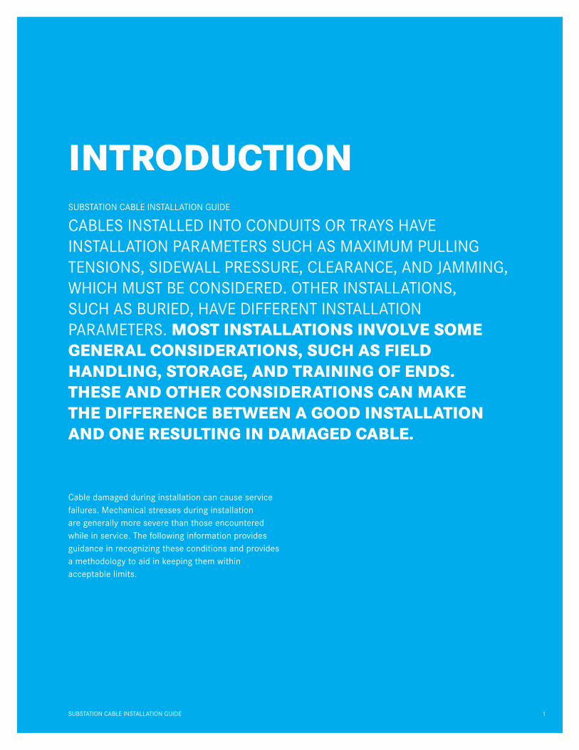
CAblES INSTAllED INTO CONDUITS Or TrAyS HAvE INSTAllATION PArAmETErS SUCH AS mAxImUm PUllING TENSIONS, SIDEWAll PrESSUrE, ClEArANCE, AND JAmmING, WHICH mUST bE CONSIDErED. OTHEr INSTAllATIONS, SUCH AS bUrIED, HAvE DIFFErENT INSTAllATION PArAmETErS. mOST InSTallaTIOnS InvOlvE SOmE gEnERal cOnSIdERaTIOnS, SUcH aS fIEld HandlIng, STORagE, and TRaInIng Of EndS. THESE and OTHER cOnSIdERaTIOnS can makE THE dIffEREncE bETWEEn a gOOd InSTallaTIOn and OnE RESUlTIng In damagEd cablE.
InTROdUcTIOn
Cable damaged during installation can cause service failures. mechanical stresses during installation are generally more severe than those encountered while in service. The following information provides guidance in recognizing these conditions and provides a methodology to aid in keeping them within acceptable limits.
1SUbSTATION CAblE INSTAllATION GUIDE

2 SUbSTATION CAblE INSTAllATION GUIDE

3
INTrODUCTION
THE Small dETaIlS can makE THE dIffEREncE bETWEEn SUccESSfUl InSTallaTIOnS and HavIng TO REmOvE damagEd cablE. IN PrEPArING FOr A CAblE PUll, IT IS JUST AS ImPOrTANT TO COvEr THE SmAll DETAIlS AS IT IS TO ASSUrE THAT THE CAblE DOES NOT ExCEED mAxImUm SIDEWAll PrESSUrE, mINImUm bENDING rADII, AND mAxImUm PUllING TENSIONS. GENErAl FIElD PrACTICES ArE PrOvIDED TO AID IN PrEPArING FOr lArGE AND SmAll CAblE INSTAllATIONS.
PrEPlANNING Preplanning for a pull is very important and should include the following steps:
1. review all applicable local, state, and federal codes.
2. Consult local inspector.
3. Consult applicable information provided by national standards, cable manufacturers, and accessory and other suppliers.
4. Check cable for:
a) Correct size and type
b) Shipping damage
c) End seals
d) Special instructions
5. Check reels for:
a) Damage
b) Protruding nails that might damage cable
c) Staples
6. Consult equipment and cable manufacturer for approval of proper pulling equipment:
a) When using wood reels, use reel jack stands to support an axle through the arbor hole during payoff.
b) Steel reels or special reinforced wood reels are acceptable for use with electric roller payoff methods. Caution: Electric rollers can severely damage or completely collapse non-reinforced wood reels during installation.
SUbSTATION CAblE INSTAllATION GUIDE
gEnERal fIEld pRacTIcES

4
lOW AmbIENT TEmPErATUrE low temperatures are a cause for concern when installing cables. Cable should be handled more carefully and pulled more slowly during cold weather. When cables are to be installed in cold weather, they should be kept in heated storage for at least 24 hours before installation. Cables should not be installed at ambient temperatures lower than the following:
TypE Of InSUlaTIOn OR JackET
mInImUm TEmpERaTURE fOR InSTallaTIOn
PvC -10°C 14°F
EPr -40°C -40°F
PE -40°C -40°F
xlPE -40°C -40°F
SOlONON® -40°C -40°F
PvC (Arctic) -40°C -40°F
CSPE (Hypalon®) or CPE -20°C -4°F Note: The minimum temperature for installation is equal to the cold bend temperature rating +15° C
In climates where there are large temperature swings either intermittently or from summer to winter, jacket movement and shrinkback can occur at splices and terminations. This is probably due to a ratcheting effect associated with the expansion and contraction cycles of the environment and cable. Under certain conditions, terminations may allow entry of moisture and contaminants into the cable, thus precipitating insulation failure. mechanical restraints, such as hose clamps and shrinkable sleeves that extend over part of the jacket and termination, that apply pressure at those points, have proven to be effective at restraining the jacket movement.1
EqUIPmENT Some of the equipment and arrangements used to install cable are illustrated in the following figures:
a) At the feed-in, the curvature of the cable feed is in the same continuous arc with no reverse bends. At the pull-out, the pulling rope exits the duct directly to a pulling sheave.
Figure F-1 Pulling Cable in Duct
b) The cable is fed from the cable reel directly into the conduit at floor level. The cable is fed from the bottom of the reel so that its curvature is continuous with no reversed bends.
Figure F-2 Cable Feed into Conduit at Floor Level
SUbSTATION CAblE INSTAllATION GUIDE
gEnERal fIEld pRacTIcES
Cable pull rope

5
c) From cable reel to cable tray, the cable is fed from the top of the reel to maintain required curvature. Sheaves, or a shoe, may be used to guide the cable into the tray.
Figure F-3 Cable Feed into Cable Tray
d) Cable sheaves or a shoe may be used to guide cable into the desired direction, maintain minimum bend radius, and reduce friction. Examples of proper and improper sheave arrangements are illustrated in the following figures.
Figure F-4 Single Sheave for 90° Change of Direction (R is radius used to calculate sidewall pressure, SP)
Figure F-5 Multiple Sheaves
Figure F-6 Sheave Arrangements for Feeding into Cable Tray
SUbSTATION CAblE INSTAllATION GUIDE
gEnERal fIEld pRacTIcES
Cable
Cable
Cable
proper
proper
improper
improper
Cable
r r
Fit
r

6
TrAINING rADIUS The training radius is the final positioning of cable ends after the cable has been placed in the raceway. These limits should not be used for cables subjected to pulling tensions during installation.
larger bend radii shall be considered for conduit bends, sheaves, or other curved surfaces around which the cable may be pulled under tension while being installed, due to sidewall bearing pressure limits (Table 4) of the cable.
nEc REcOmmEndEd mInImUm bEndIng RadII
Single and multiple Conductors over 600 Volts
multiple of Cable oD
Shielded and Nonarmored (NEC 300.34) 12
Nonshielded and Nonarmored 8
multiconductor or multiplexed Cable 12/7*
Type TC (Tray Cable) (NEC 336.24) **
* 12 times individual shielded conductor diameter or 7 times overall cable diameter, whichever is greater.
**Reference Table 1
A nonshielded cable can tolerate a sharper bend than a shielded cable. When bent too sharply, helical or longitudinally corrugated metal tapes can separate, buckle, and cut into the insulation. This problem is compounded by jackets concealing such damage.
HANDlING AND STOrAGE GUIDElINES
• Unloading equipment should not come in contact with the cable or its protective covering.
• If a crane is used to unload cable, a shaft through the arbor hole or a cradle supporting both reel flanges should be used.
•Forklifts must lift the reel by contacting both flanges.
• ramps must be wide enough to support both reel flanges.
• Store reels on hard surface so that the flanges will not sink and allow reel weight to rest on cable.
Figure F-7 Proper Reel Handling
SUbSTATION CAblE INSTAllATION GUIDE
gEnERal fIEld pRacTIcES

7SUbSTATION CAblE INSTAllATION GUIDE
gEnERal fIEld pRacTIcES
Figure F-8 Improper Reel Handling
• reels should be stored out of harm’s way. Consider both physical and environmental hazards.
• Cable ends must always be sealed to prevent the entrance of moisture, etc.
•remove temporary cable lashing.
• While pulling, in order to eliminate sharp bends and crossovers, always have a person feed the cable(s) straight into the conduit by hand or, for larger cables, over a large diameter sheave.
Figure F-9 Feed Into Conduit
Do not pull cable directly across short, sharp angles. After pulling completely out of one side of the enclosure, feed cable into the other side of the enclosure and pull that segment.
Figure F-10 Pull-Through Enclosure
Proper ImproperProper Improper
Proper Improper

8 SUbSTATION CAblE INSTAllATION GUIDE

9
CAlCUlATIONS SHOUlD bE mADE TO INDICATE WHETHEr THE PUll lOOkS “EASy” Or “ImPOSSIblE,” mAkING THE DECISION TO PUll AN ObvIOUS CHOICE. WHEn a “maRgInal” SITUaTIOn IS EncOUnTEREd, THE EnTIRE pUll SHOUld bE REvIEWEd. THIS REvIEW may InclUdE mORE RIgOROUS calcUlaTIOnS OR TRIal pUllS. A FINAl DECISION SHOUlD bE mADE bASED ON INSTAllATION FACTOrS kNOWN TO THE END USEr AND INSTAllEr.
SUbSTATION CAblE INSTAllATION GUIDE
InSTallaTIOn In cOndUIT
The sizes of the conduit are determined based on the calculations of the clearances, jamming, and fill. Pulling tensions may then be evaluated by determining the maximum tension based on the pulling device used and the maximum tension that can be applied to the conductors. The lesser of these two values is the maximum allowable tension (T
m).
The pulling tension (T) required to pull the cable through the conduit is then calculated and compared to the maximum allowable tension. If the pulling tension exceeds the allowable tension, conditions should be changed to ensure a successful pull. After calculating pulling tensions, sidewall pressures (SP) may be calculated.
For further study on this subject, AEIC Publication CG5-2005 and IEEE Standard 1185 present additional details.2

AllOWAblE TENSION ON PUllING DEvICE Do not exceed the allowable tension stated by the manufacturer of the pulling eye or 10,000 pounds, whichever is less. Traditional conservative practices limit the allowable tension of a basket grip to 1,000 pounds. Under specific conditions, this limit can be safely exceeded.
Definitions for the following equations and examples:
Tc
tension on each conductor, in pounds
S allowable stress, in pounds/cmil
A area of each conductor, in cmil
N number of conductors
Tcable
maximum allowable tension in the cable, in pounds
Tdevice
maximum allowable tension on device, in pounds
Tm maximum allowable tension is the lesser of T
device or T
cable , in pounds
TAblE 1
maXimum aLLowaBLe ConDuCtor StreSS (S)
cable Type material Temper lb/cmil
All Copper Soft 0.008
Power Aluminum Hard 0.008
Power Aluminum 3/4 Hard 0.006
Power Aluminum AA-8000* 0.006
UrD Aluminum 1/2 Hard 0.003
Solid Aluminum Soft 0.002
10 SUbSTATION CAblE INSTAllATION GUIDE
InSTallaTIOn In cOndUIT
• 3/4 hard aluminum is allowed for power cable. The 2005 NEC defines use of AA-8000 for solid (8, 10, and 12 AWG) and stranded (8 AWG through 1000 kcmil) conductors.
11SUbSTATION CAblE INSTAllATION GUIDE
InSTallaTIOn In cOndUIT
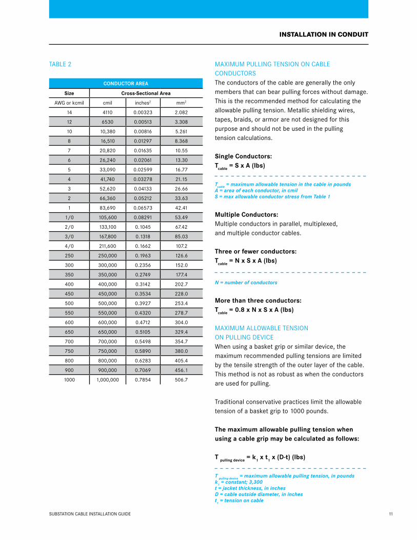
TAblE 2
ConDuCtor area
Size Cross-Sectional area
AWG or kcmil cmil inches2 mm2
14 4110 0.00323 2.082
12 6530 0.00513 3.308
10 10,380 0.00816 5.261
8 16,510 0.01297 8.368
7 20,820 0.01635 10.55
6 26,240 0.02061 13.30
5 33,090 0.02599 16.77
4 41,740 0.03278 21.15
3 52,620 0.04133 26.66
2 66,360 0.05212 33.63
1 83,690 0.06573 42.41
1/0 105,600 0.08291 53.49
2/0 133,100 0.1045 67.42
3/0 167,800 0.1318 85.03
4/0 211,600 0.1662 107.2
250 250,000 0.1963 126.6
300 300,000 0.2356 152.0
350 350,000 0.2749 177.4
400 400,000 0.3142 202.7
450 450,000 0.3534 228.0
500 500,000 0.3927 253.4
550 550,000 0.4320 278.7
600 600,000 0.4712 304.0
650 650,000 0.5105 329.4
700 700,000 0.5498 354.7
750 750,000 0.5890 380.0
800 800,000 0.6283 405.4
900 900,000 0.7069 456.1
1000 1,000,000 0.7854 506.7
mAxImUm PUllING TENSION ON CAblE CONDUCTOrSThe conductors of the cable are generally the only members that can bear pulling forces without damage. This is the recommended method for calculating the allowable pulling tension. metallic shielding wires, tapes, braids, or armor are not designed for this purpose and should not be used in the pulling tension calculations.
Single Conductors:tcable = S x a (lbs)
Tcable = maximum allowable tension in the cable in poundsA = area of each conductor, in cmil S = max allowable conductor stress from Table 1
multiple Conductors:multiple conductors in parallel, multiplexed, and multiple conductor cables.
three or fewer conductors: tcable = n x S x a (lbs)
N = number of conductors
more than three conductors:tcable = 0.8 x n x S x a (lbs)
mAxImUm AllOWAblE TENSION ON PUllING DEvICEWhen using a basket grip or similar device, the maximum recommended pulling tensions are limited by the tensile strength of the outer layer of the cable. This method is not as robust as when the conductors are used for pulling.
Traditional conservative practices limit the allowable tension of a basket grip to 1000 pounds.
the maximum allowable pulling tension when using a cable grip may be calculated as follows:
t pulling device = k1 x t1 x (D-t) (lbs)
T pulling device = maximum allowable pulling tension, in poundsk1 = constant; 3,300t = jacket thickness, in inchesD = cable outside diameter, in inchest1 = tension on cable
12 SUbSTATION CAblE INSTAllATION GUIDE
InSTallaTIOn In cOndUIT
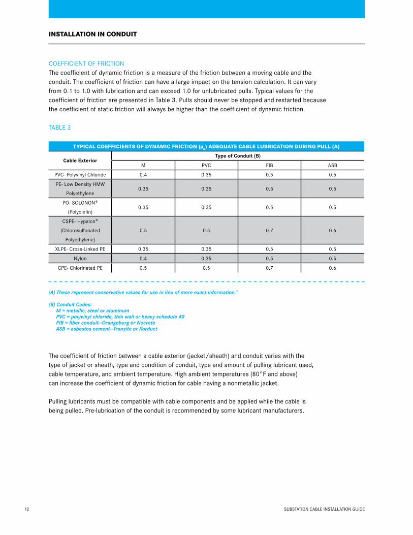
COEFFICIENT OF FrICTION The coefficient of dynamic friction is a measure of the friction between a moving cable and the conduit. The coefficient of friction can have a large impact on the tension calculation. It can vary from 0.1 to 1.0 with lubrication and can exceed 1.0 for unlubricated pulls. Typical values for the coefficient of friction are presented in Table 3. Pulls should never be stopped and restarted because the coefficient of static friction will always be higher than the coefficient of dynamic friction.
TAblE 3
TypIcal cOEffIcIEnTS Of dynamIc fRIcTIOn (µk) adEQUaTE cablE lUbRIcaTIOn dURIng pUll (a)
Cable exterior type of Conduit (B)
m PvC FIb ASb
PvC- Polyvinyl Chloride 0.4 0.35 0.5 0.5
PE- low Density HmW
Polyethylene 0.35 0.35 0.5 0.5
PO- SOlONON®
(Polyolefin) 0.35 0.35 0.5 0.5
CSPE- Hypalon®
(Chlorosulfonated
Polyethylene)
0.5 0.5 0.7 0.6
xlPE- Cross-linked PE 0.35 0.35 0.5 0.5
Nylon 0.4 0.35 0.5 0.5
CPE- Chlorinated PE 0.5 0.5 0.7 0.6
(A) These represent conservative values for use in lieu of more exact information.3
(B) Conduit Codes: M = metallic, steel or aluminum PVC = polyvinyl chloride, thin wall or heavy schedule 40 FIB = fiber conduit—Orangeburg or Nocrete ASB = asbestos cement—Transite or Korduct
The coefficient of friction between a cable exterior (jacket/sheath) and conduit varies with the type of jacket or sheath, type and condition of conduit, type and amount of pulling lubricant used, cable temperature, and ambient temperature. High ambient temperatures (80°F and above) can increase the coefficient of dynamic friction for cable having a nonmetallic jacket.
Pulling lubricants must be compatible with cable components and be applied while the cable is being pulled. Pre-lubrication of the conduit is recommended by some lubricant manufacturers.

SIDEWAll PrESSUrESidewall Pressure (SP) is exerted on a cable as it is pulled around a bend. Excessive sidewall pressure can cause cable damage and is the most restrictive factor in many installations.
Figure F-11 Sidewall Pressure Factors
Sidewall pressure is calculated as follows:
For one single-conductor cable or multiple-conductor cable under a common jacket
For three single-conductor cables, cradled
For three single-conductor cables, triangular
where: T = tension coming out of the bend in pounds (See Table 2 for sweep elbows only) R = bend radius, in feet w = weight correction factor, dimensionless SP = sidewall pressure in pounds/foot
recommended maximum sidewall pressures are provided in Table 4 in the range of 300 to 500 pounds per foot, depending on type of cable. The AEIC publication “Underground Extruded Power Cable Pulling Guide” provides maximum sidewall pressures ranging from 1,000 to 2,000 pounds per foot depending on construction. Consult the cable manufacturer prior to using these higher values.
TAblE 4
reCommenDeD maXimum SiDewaLL preSureS
cable Type Sp lbs/ft.
300 v nonshielded, 300 v & 600 v shielded C&I
500
600 v nonshielded C&I 500
600 v - 1 kv nonshielded power 500
5 - 15 kv Power 500
25 - 35 kv Power 300
Interlocked armored (All voltage Classes)
300
JAmmING Jamming is the wedging of three or more cables when pulled into a conduit. This usually occurs because of crossovers when the cables twist or are pulled around bends. The jam ratio is the ratio of the conduit inner diameter (D) and the cable outside diameter (d).
The probability for jamming is presented in Figure F-12
Figure F-12 Jamming Probabilities Using the Jam Ratio
In calculating jamming probabilities, a 5% factor was used to account for the oval cross-section of conduit bends.
The cable diameters should be measured, since actual diameters may vary from the published nominal values.
13
InSTallaTIOn In cOndUIT
Jam ratio =
Sp =
D
dt
r
Sp=(3w-2) •t
3r
Sp=w •t
2r
t
Sp
r
Very Small Very SmallSmall Small
2.4 2.5 2.6 2.9 3.0 3.2
Moderate ModerateSignificant

CAblE lUbrICATION SElECTION1. reducing the coefficient of friction is the
primary factor in the selection of a lubricant.
2. Compatibility of the lubricant with cable and conduit is extremely important. The lubricant should not have any deleterious effects on the conduit or on the physical or electrical properties of the cable insulation, semiconducting, or jacket materials.4
3. The lubricant and its residue should not propagate flame.
4. The lubricant should be Ul or CSA listed.
5. The lubricant should contain no waxes or greases.
USE The cable jacket and/or conduit walls should be completely lubricated. The lubricant should be applied immediately before—and/or—during the pull. This quantity should be increased as needed for difficult pulling situations.
An estimate of the quantity of required lubricant can be determined from the following equation.5
Q=(0.0015) L•D
where: Q = quantity, in gallons L = conduit length, in feet D = outside diameter of cable or inside
diameter of conduit, in inches
InSTallaTIOn In cOndUIT
14 SUbSTATION CAblE INSTAllATION GUIDE
15SUbSTATION CAblE INSTAllATION GUIDE
WHEN PUllING CAblE INTO CAblE TrAyS THE SAmE APPrOACH SHOUlD bE USED FOr CAblE INSTAllED INTO CONDUIT. caRE mUST bE gIvEn TO THE RUn lEngTHS, nUmbER Of cablE TURnS, and cablE SHEavE SIzE TO EnSURE THE cablE’S maxImUm pUllIng TEnSIOn, mInImUm bEndIng RadIUS, and maxImUm allOWablE SIdEWall pRESSURE aRE nOT ExcEEdEd, SUbJEcTIng THE cablE TO pOSSIblE damagE.
InSTallaTIOn In cablE TRay
rOllErS AND SHEAvES When pulling around bends in cable tray, excessive sidewall pressure can damage the cable. Sidewall pressure can be reduced by using a large radius sheave. many times, a large radius sheave cannot be used and an assembly of multiple smaller sheaves is used. Care should be given to prevent damage due to high sidewall pressure on the individual sheaves. The individual sheaves should have a minimum inside radius of 1.25 inches with at least one sheave per 20° of the bend. A three-sheave assembly for a 90° bend should never be used.
rollers and sheaves must be well-maintained and lubricated to achieve the lowest possible coefficient of friction.
roller mounting • rollers must be properly spaced to prevent
the cable from touching the tray. • rollers must be free-turning. • When the tray changes direction, vertically
or horizontally, sheave radii must be large enough to meet the minimum bending and maximum allowable sidewall pressure limits.
roller Spacing roller spacing will vary with: • Cable weight • Cable tension • Cable construction • roller height above the tray

16
To estimate roller spacing, the following equation can be used:
where: s = distance between rollers, in feet h = height of top roller above the tray bottom, in feet T = tension, in pounds w = weight of cable, per foot
The distance will be conservative for armored cable because the equation assumes a perfectly flexible cable. When possible, a length of cable should be used to determine maximum spacing under no tension—as a check for the calculated values.
PUllING TENSIONS Calculations of pulling tensions for cable trays are similar to those for pulling cable in conduit, adjusting the coefficient of friction to reflect using rollers and sheaves.
HOrIzONTAl STrAIGHT SECTIONS The tension for a horizontal straight section of cable tray can be estimated with the following equation:
where: Tout = tension out of a section, in pounds µ = coefficient of dynamic friction (= 0.15) W = total cable assembly weight, in pounds/foot L = straight section length, in feet Tin = tension into a section, in pounds
The coefficient of friction µ equal to 0.15 accounts for the low-rolling friction of well-maintained rollers.
inclined Straight Sections Use the following equation for pulling up an inclined straight section:
Use the following equation for pulling down an inclined straight section:
where: Tout = tension out of a section, in pounds W = total cable assembly weight, in pounds/foot Ø = straight section angle from horizontal, in radians L = straight section length, in feet µ = coefficient of dynamic friction ( =0.15) Tin = tension into a section, in pounds
vErTICAl SECTIONS When pulling straight up or down, the equation for inclined pulls simplifies to the following equations:
pulling Straight up
pulling Straight Down
where: W = total cable assembly weight, in pounds/foot L = straight vertical section length, in feet Tin = tension into a section, in pounds Tout = tension out of a section, in pounds
SUbSTATION CAblE INSTAllATION GUIDE
InSTallaTIOn In cablE TRay
s =
tout = µwL + tin
tout = wL + tin
tout = wL (sinØ + µ cosØ) + tin
tout = – wL (sinØ - µ cosØ) + tin
tout = –wL + tin
8ht
w

17
TENSION IN bENDS If the sheaves in the bends in cable trays are well-maintained, they will not have the multiplying effect on tension that bends in conduit have. The sheaves will turn with the cable, allowing the coefficient of friction to be assumed zero. This results in the commonly-used approximation for conduit bend equation (ewµØ) becoming one. Even though cable tray bends produce no multiplying effect, it is essential for heavier cables to include the force required to bend the cable around the sheave. If the sheaves are not well-maintained, the bend will have a multiplying effect. The tension in the pull must then be calculated using the same equations used for installations in conduit.
TENSION ENTErING CAblE TrAy because the tension entering the cable tray is rarely zero, it is critical that the tension required to remove the cable from the reel be used to calculate the total tension for the installation.
many times it is difficult to know the location of the reel of cable until the cable is being installed. The following equations are used to approximate the tension entering the cable tray and can be used to determine how critical the reel position will be for the cable pull.
Feeding off reel horizontally When the cable reel can be elevated so that the cable can be pulled directly into the tray, the following equation should be used to approximate the tension required to remove the cable from the reel:
treel = 25w
where: Treel = tension, in pounds W = total cable assembly weight, in pounds/foot
Feeding off reel Vertically When the cable reel must be positioned directly below the cable tray, the following equation should be used to approximate the tension required to pull the cable into the tray.
t = wL
where: W = total cable assembly weight, in pounds/foot L = straight vertical section length, in feet T = tension, in pounds
The tension can now be approximated for pulling the cable into the tray from a horizontal position when the reel is placed directly under the tray. To estimate the tension entering the cable tray when the reel must be placed away from and below the entrance to the tray, use the equation for feeding off the reel vertically where the height (l) is the vertical distance between the reel and cable tray. To allow for bending forces as the cable comes off the reel, the minimum tension added should be 25W.
SUbSTATION CAblE INSTAllATION GUIDE
InSTallaTIOn In cablE TRay
18 SUbSTATION CAblE INSTAllATION GUIDE

19
cablES bURIEd dIREcTly In EaRTH The NEC, NESC, and IEEE provide basic information regarding direct burial of electrical cables.6
DEPTH OF bUrIAl 1. The depth of burial shall be sufficient to protect
the cable from damage imposed by expected surface usage.
2. burial depths as indicated in Table 5 are considered adequate for supply cables or conductors, except as noted in a, b, or c.
Figure F-13 Typical Burial Cross-Section
TAblE 5
nESc TablE 352-1 SUpply cablE OR cOndUcTOR bURIal dEpTH
voltage Phase to Phase Depth of burial(in.)
(mm)
0 to 600 24 600
601 to 50,000 30 750
50,001 and above 42 1070
EXCEPTION: Street light cables operating at not more than 150 V to ground may be buried at a depth not less than 18 in. (450mm).
a) In area where frost conditions could damage cables, burial depths should be greater.
b) Lesser depths may be used where supplemental protection is provided. The supplemental protection should be sufficient to protect the cable from damage imposed by expected surface usage.
c) Where the surface is not to final grade, the cable should be placed to meet or exceed the requirements indicated above, both at the time of installation and when the surface is to final grade.
TrENCHING The bottom of the trench should be smooth, undisturbed, well-tamped earth or sand. When excavation is in rock or rocky soils, the cable should be laid on a protective layer of well-tamped backfill. backfill within 4 inches of the cable should be free of materials that may damage the cable. backfill should be adequately compacted. machine compaction should not be used within 6 inches of the cable.
A protective covering above the cable will warn excavators of the presence of an underlying cable.
PlOWING Plowing of cable should not result in damage to the cable from rocks or other solid materials. The design of cable plowing equipment and the plowing of cable should not damage the cable by exceeding bend, sidewall pressure, cable tension, or other allowable limits.
Compacted Backfill
6˝ to 8˝
3˝ to 4˝
Optional Protective Cover
Tamped Sand or Stone-Free Earth
Tamped Soft Bedding of Sand or Stone-Free Earth

A JACkETED mUlTICONDUCTOr IS PrEFErAblE TO THE INSTAllATION OF SINGlE-CONDUCTOr CAblES TO EASE INSTAllATION AND AvOID CrOSSOvErS. UNDEr vEHICUlAr AND PEDESTrIAN TrAFFIC WAyS, IT IS GOOD PrACTICE TO PUll CAblE THrOUGH A CONDUIT.
SUpplEmEnTal InfORmaTIOn
20 SUbSTATION CAblE INSTAllATION GUIDE

21SUbSTATION CAblE INSTAllATION GUIDE
THE PUrPOSE OF THIS SECTION IS TO SUmmArIzE PrOCEDUrAl AND TECHNICAl INFOrmATION FOr THE PErFOrmANCE OF FIElD TESTING CAblE SySTEmS. THE PrOCEDUrAl ASPECTS COvEr SUbJECTS rElATED TO PErSONNEl AND SAFETy, bUT ArE NOT INTENDED TO bE All-INClUSIvE.
fIEld TESTIng
manufacturers perform various electrical tests on finished wire and cable products to ensure they can safely handle their maximum voltage and current ratings. Some installation procedures—such as pulling through conduit, installation into cable trays, or framing members — can damage conductors and cables enough to create an electrical hazard. For example, incorrect calculations of pulling force, sidewall pressure, or conduit fill may lead to the tearing of a conductor’s insulation as it is pulled through conduit. because post-installation testing is a good general practice, some installation contracts may require testing by the installer.
SAFETy Electrical tests can be dangerous and should be conducted by personnel who are qualified to perform the tests. both low-potential and high-potential testing have inherent hazards to personnel and equipment. Thus, a thorough understanding of the safety rules, test equipment, wiring system, and connected equipment is essential in preventing damage to the conductors and equipment, and in preventing electrical shock to the persons performing the tests. IEEE Standard 510 typifies recommended industry practices for safely conducting field testing.7
22 SUbSTATION CAblE INSTAllATION GUIDE
PrEPArATION FOr TESTING before conducting tests on any cable system, verify that the cable system is properly de-energized. If the cable system has been previously energized, you must follow the prescribed rules for conducting the switching necessary to de-energize, lock-out, tag, and ground the cable system.
High-voltage conductors that are energized can induce voltage in ungrounded conductors in close proximity. It is good practice, therefore, to disconnect cables from non-cable system equipment and to ground all conductors not under test for safety concerns and to prevent erroneous test results. In the case of high-voltage testing, disconnecting the cable will prevent damage to equipment and apparatus.
Check that adequate physical clearances exist between the cable ends and other equipment, other energized conductors, and to electrical ground. At all ends remote from where the test equipment is to be connected, position a personnel guard, or barricade the area to prevent unauthorized access to the cable system under test.
NOTE: Verify the procedures are taken to clear all tap(s) or lateral(s) in the circuit.
remove grounds from the cable phase to be tested. Phases not under test are to remain grounded at all ends.
CONDUCTING TEST Follow the instructions provided by the manufacturer of the test equipment for its proper operation. Conduct test in accordance with prescribed procedures and instructions. record test results and retain for future reference.
CONClUSION OF TESTING maintain grounds on all conductors until the test equipment is disconnected and packed for removal.
Caution: For HvDC tests, the accumulation of a potentially dangerous voltage can remain on the cable system if the conductors have not been grounded for a sufficient time period after the completion of the test. A rough guide is to maintain the grounds for one to four times the test duration before they are removed and the cable is reconnected into the circuit.8
Follow prescribed procedures to return or place the cable circuit into service.
CAblE SySTEm INTEGrITy During the design of the substation cable system, it is appropriate to evaluate the requirements of the field acceptance tests that can determine the integrity of the installed system. The following types of tests may be readily conducted:
Conductor Continuity Tests for conductor continuity can include a simple check with an ohmmeter, 500-volt megohm meter, or a device that measures conductor resistance. This test determines if the conductors complete an electrical circuit by ensuring the conductor metal has not been broken.
metallic Shield Condition For shielded cables, the metallic component of the insulation shield of jacketed cables can be tested for its condition. A continuity test can be accomplished with an ohmmeter or megohm meter tester. A more complex test arrangement is required to measure the value of the shield resistance. A comparison of the shield resistance value can then be made against specified values.
Jacket integrity Insulating jackets of directly-buried or water-submerged cables can be tested for insulation resistance (Ir). It may be possible to test integrity of conductive, nonmetallic jackets or sheaths.
fIEld TESTIng

23SUbSTATION CAblE INSTAllATION GUIDE
SUbSTATION CONTrOl CAblES CONTAIN mANy DIFFErENT TyPES OF SHIElDS.
SHIEld gROUndIng
To list just a few:• Helical copper tape• longitudinal corrugated copper tape• Helical aluminum tape• Aluminum polyester foil tape• Aluminum tape with co-polymer
coating (1 or 2 sided)• Copper braid
The proper method to terminate the shield should be determined by the owner. This guide provides typical termination methods that may be used. The critical issue is that a stable, low resistance electrical connection is made between the shield and ground.Shielded control cables may or may not contain a drain wire. When present, the drain wire is continuously in contact with the metallic shield making terminating easy. The illustrations shown below are applicable for any type of shield. When a drain wire is not present, care must be taken to ensure a solid connection is made between the shield and ground.

24
SHIElDED CONTrOl CAblE WITH A DrAIN WIrEWhen a drain wire is present, termination is made easy. No matter what type of metallic shield is used, the steps to terminate will be the same. Shown below is a control cable with the drain wire in contact with an aluminum foil tape backed with a polyester film.
SUbSTATION CAblE INSTAllATION GUIDE
SHIEld gROUndIng
1. remove jacket as needed for terminating. The jacket provides mechanical protection, so only remove the length that is necessary.
2. apply vinyl electrical tape approximately 1” above jacket in order to hold shield in place.
3. unravel shield from the end of the cable to expose the conductors back to the tape.

25SUbSTATION CAblE INSTAllATION GUIDE
SHIEld gROUndIng
4. Choose the appropriate size lug for the drain wire. many different types of lugs exist. Shown is just an example.
5. insert the lug onto the drain wire. be sure drain wire can be seen at the end.
6. Crimp the lug. be sure to use the crimping tool that was designed for that specific lug.
7. Finish terminating conductors.

26 SUbSTATION CAblE INSTAllATION GUIDE
SHIEld gROUndIng
SHIElDED CONTrOl CAblE WITHOUT A DrAIN WIrE When a drain wire is not present, there are many different types of connectors that can be used. One example is shown below:
aluminum tape with two Sided Co-polymer Coating
1. remove shield/jacket as needed for termination on device. For maximum shield effectiveness, only remove the portion of shield necessary.
2. Cut shield/jacket approximately 1” to allow insertion of connector.
3. insert bottom of connector approximately 90° from the slit opening. Connector should easily slide between shield/jacket and conductors.
4. place the connector top onto the stud.

27SUbSTATION CAblE INSTAllATION GUIDE
SHIEld gROUndIng
5. install securing nut. Tighten nut until snug and teeth on connector top bite into jacket. The teeth will penetrate the coating giving good connection to the aluminum.
6. apply vinyl electrical tape over connector.
7. prepare ground conductor and install on top of securing nut.
8. install remaining securing nut. Installation is complete.

28 SUbSTATION CAblE INSTAllATION GUIDE
The use of a constant force spring is another common method for terminating the shield when a drain wire is not present.
SHIEld gROUndIng
29SUbSTATION CAblE INSTAllATION GUIDE
r.C. rIFENbErG, “PIPE lINE DESIGN FOr PIPE TyPE FEEDErS,” IN “AIEE TrANSACTIONS ON POWEr APPArATUS AND SySTEmS” (DECEmbEr 1953), vOlUmE 8, PAPEr NO. 53-389.
ANSI/IEEE STANDArD 525-2007, “IEEE GUIDE FOr THE DESIGN AND INSTAllATION OF CAblE SySTEmS IN SUbSTATIONS.” ANSI/IEEE STANDArD 690, “IEEE STANDArD FOr THE DESIGN AND INSTAllATION OF CAblE SySTEmS FOr ClASS 1E CIrCUITS IN NUClEAr POWEr GENErATING STATIONS. 2002.”
T.A. bAlASkA AND A.l. mCkEAN, “FAUlT lOCATION ExPErIENCE AND PrACTICE ON INDUSTrIAl SySTEmS,” 1966 IEEE SPECIAl TECHNICAl CONFErENCE ON UNDErGrOUND, CHICAGO, Il.
1. IEEE 532-2007 “GUIDE FOr SElECTING AND TESTING JACkETS FOr UNDErGrOUND CAblES.”
2. AEIC PUblICATION NO CG5-2005, “UNDErGrOUND ExTrUDED POWEr CAblE PUllING, AEIC TASk GrOUP 28,” 2005; AND IEEE STANDArD 1185-1994, “GUIDE FOr INSTAllATION mETHODS FOr GENErATING STATION CAblES.”
3. GENE C. NEETz, “COEFFICIENT OF FrICTION mEASUrEmENT bETWEEN CAblE AND CONDUIT SUrFACES UNDEr vAryING lOADS,” IN 1985 IEEE TrANSACTIONS ON POWEr APPArATUS AND SySTEmS, vOl. PAS-104, NO. 1, PP. 16-21.
4. IEEE STANDArD 400-2012. “STANDArD TESTS FOr DETErmINING COmPATIbIlITy OF CAblE-PUllING lUbrICANTS WITH WIrE AND CAblE.”
5. POlyWATEr, “TECHNICAl TAlk,” vOlUmE 4.
6. NEC, SECTION 300.5; NATIONAl ElECTrICAl SAFETy CODE (NESC), 2012 EDITION, SECTION 35; “ANSI C2-2002, SECrETArIAT IEEE.”
7. IEEE STANDArD 510-1992, “rECOmmENDED PrACTICES FOr SAFETy IN HIGH vOlTAGE AND HIGH POWEr TESTING.”
8. IEEE STANDArD 400-2012. “GUIDE FOr FIElD TESTING AND EvAlUATION OF THE INSUlATION OF SHIElDED POWEr CAblE SySTEmS.”
REfEREncE pUblIcaTIOnS

SOUTHWIRE cOmpany
SUbSTaTIOn cablEInSTallaTIOn gUIdE
Southwire CompanyOne Southwire DriveCarrollton, Georgia 30119
800-444-1700www.southwire.com
edition 2013.1