Embed Size (px)
Citation preview

S u b s e a We l l
D e v e l o p m e n t a n d F a t i g u e
A n a l y s i s
T h i r d E d i t i o n
M a r c h , 2 0 1 7
J . K o t o
P u b l i s h e d B y
O c e a n & A e r o s p a c e R e s e a r c h I n s t i t u t e ,
I n d o n e s i a
S u b s e a We l l
D e v e l o p m e n t a n d F a t i g u e A n a l y s i s
T h i r d E d i t i o n
J . K o t o
Ocean & Aerospace Research Institute, Indonesia

Authors :
J. Koto
ISBN :
978-602-51777-7-4
Editor :
Jaswar Koto
Book No:
2003201702
Publisher :
Ocean & Aerospace Research Institute (OcARI), Indonesia
Resty Menara Group, Jl. Sisingamangaraja 102,
Rintis, LimaPuluh, Kota Pekanbaru, Riau 28156, INDONESIA
Telp/Fax : +62761 32744
http://isomase.org/OCAri/Home.php
All rights reserved
Reproduction of this work in any form and by any means without the written permission of the
publisher is prohibited
S u b s e a We l l
D e v e l o p m e n t a n d F a t i g u e A n a l y s i s

Subsea Well Development and Fatigue Analysis
Published by Ocean & Aerospace Research Institute, Indonesia | Preface 1
Preface
This book introduces basic education on subsea well development for students, fresh
offshore engineers and universities’ staffs. The book consists of six chapters as follows:
The first chapter discusses overview of subsea well. In the second chapter, drilling subsea
well, subsea well specification, subsea well construction, subsea well completion and
standard and code practiced used in subsea technology are explained in detailed with an
example. The third chapter discusses subsea blowout preventer (BOP) and how to control
BOP during drilling rig. The forth chapter comes up with subsea wellhead components
and wellhead guide system, the fifth chapter discusses on subsea well test and completion
using senTHREE-7 as an example and wellhead fatigue analysis is discussed in the last
chapter using Subsea Pro -Simulation & Installation- Software.
Many pictures and illustrations are enclosed in this book to assist the readers’
understanding. It should be noted that some pictures and contents are borrowed from
other companies’ websites and brochures which are quoted and listed in the references.
This book mainly is designed for basic education on subsea engineering purposes only
not for traded.
2017 (Third Edition)

Subsea Well Development and Fatigue Analysis
Published by Ocean & Aerospace Research Institute, Indonesia | Acknowledgements 2
Acknowledgements
Alhamdulillahhirobbilalamin, first and foremost, all praises and syukur are only to Allah
(S.W.T) to give us strength and ability to complete this book.
We would like to take this opportunity to express our highest appreciation to our
colleagues and friends in the Ocean and Aerospace Research Institute, Indonesia,
Universiti Teknologi Malaysia (UTM) and Institut Teknologi Sepuluh Nopember (ITS),
Indonesia to provide proper guidance, full support, encouragement, invaluable ideas,
comment, recommendation, critics, suggestions and advice that to assist us for the
successful completion of this book.
To our families that always pray for our successful, all this things cannot pay for all what
they all have done. Our special thanks also to our postgraduate students.
Above this all, our highest praises, thanks and syukur to Almighty Allah Subhanahu
Wa’Talla, the most gracious the most merciful, who gave us the knowledge, courage and
patience to accomplish this project. May the peace and blessings of Allah be upon
Prophet Muhammad Sallallahu Alaihi Wasallam.
The authors are grateful to all friends, institutions and parties for supporting this book.
Subsea Well Development and Fatigue Analysis
Published by Ocean & Aerospace Research Institute, Indonesia | List of Figures 3
List of Figures
Figures Description Pages
Figure.1.1 Types of oil and Gas Traps 13
Figure.1.2 Subsea wellhead suppliers 14
Figure.2.1 Examples of offshore rigs 16
Figure.2.2 Examples of drilling rigs 17
Figure.2.3 Sequences of well drilling using drilling riser operated from
MODU
19
Figure.2.4 An example of deep water drilling rigs 20
Figure.2.5 BOP installed on Jack-up during drilling in shallow water 21
Figure.2.6 BOP on top wellhead at seabed during drilling in deep water 22
Figure.2.7 Semi-Submersible and drill ship drilling rig 24
Figure.2.8 Simple beam
Figure.2.9 Second moments of area
Figure.2.10 Equilibrium of static force
Figure.2.11 Running the temporary guide base 26
Figure.2.12 Running the drill-bit to drill the 36-in hole 27
Figure.2.13 Running the 30-in casing and PGB 28
Figure.2.14 Installing the diverter 30
Figure.2.15 Running the surface casing and High Pressure Well Head
Housing
32
Figure.3.1 Ram and Annular BOP on top of wellhead 36
Figure.3.2 Typical layout of a BOP 38
Figure.3.3 Typical types of a BOP 39
Figure.3.4 Part description ram-type BOP 40
Figure.3.5 Typical types of Ram’s BOP 41
Figure.3.6 Typical pipe ram BOP 41
Figure.3.7 Typical blind rams BOP 42
Figure.3.8 Typical shear rams BOP 42
Figure.3.9 Typical blind-shear rams BOP 43

Subsea Well Development and Fatigue Analysis
Published by Ocean & Aerospace Research Institute, Indonesia | List of Figures 4
Figure.3.10 Typical variable-bore rams BOP 43
Figure.3.11 Two typical types of Annulus’ BOP 44
Figure.3.12 Diagram of the wedge-faced BOP 45
Figure.3.13 Diagram of spherical BOP 46
Figure.3.14 Typical Rotational BOP 47
Figure.3.15 Typical Diverters BOP 48
Figure.3.16 Typical subsea BOP used in North Sea Operation 49
Figure.3.17 Common typical well control system 50
Figure.4.1 Wellhead casing design for North Sea Operation 53
Figure.4.2 Subsea wellhead system 55
Figure.4.3 An example of a subsea wellhead 58
Figure.4.4 An example of casing head 59
Figure.4.5 An example of casing hanger 59
Figure.4.6 Intermediate Casing Hanger Profile 60
Figure.4.7 An example of tubing head 61
Figure.4.8 An example of tubing hanger 63
Figure.4.9 Schematic of wellhead housing 63
Figure.4.10 Intermediate Casing Hanger Profile 64
Figure.4.11 SS-15 Subsea Wellhead System running tool family 65
Figure.4.12 SS-Series Conductor Wellhead Running Tool 66
Figure.4.13 SS-Series Subsea Wellhead Running Tool 67
Figure.4.14 Casing Hanger Running Tool 67
Figure.4.15 BOP Isolation Test Tool 69
Figure.4.16 Nominal bore protector, 133/8-in. wear bushing, and 95/8-in.
wear bushing
70
Figure.4.17 Typical Low-Pressure Wellhead Housings 70
Figure.4.18 SS type of High-Pressure Wellhead Housings 71
Figure.4.19 Typical casing design for Central North Sea 73
Figure.4.20 Typical lithology at Central North Sea 74
Figure.4.21 An example of drilling guide base 75
Figure.4.22 An example typical Permanent Guide Base 76
Figure.4.23 An example of permanent Guide Base 77
Subsea Well Development and Fatigue Analysis
Published by Ocean & Aerospace Research Institute, Indonesia | List of Figures 5
Figure.4.24 Schematic of permanent guide base 78
Figure.5.1 Well Completion methods 79
Figure 5.2 Open-hole well completion technique 80
Figure.5.3 Screen well completion technique 81
Figure.5.4 Casing or liner well completion technique 82
Figure.5.5 An example well testing 83
Figure.5.6 Subsea well suspension 84
Figure.5.7 BOP stack temporary removed from well 85
Figure.5.8 Tree and BOP installations 86
Figure.5.9 Well Completion 88
Figure.5.10 Installation and intervention 89
Figure.5.11 Isolation and Production Preparation 91
Figure.6.1 Flowchart of wellhead fatigue analysis process 94
Figure.6.2 Methods for integrating/separating global and local analyses
Figure.6.3 (a) In left column, examples of important items for system and
global model. For each item, alternative characteristics and
method options when conducting wellhead fatigue analysis
101
Figure.6.3 (b) In left column, examples of important items for local model and
fatigue damage calculation. For each item, alternative method
options when conducting wellhead fatigue analysis
102
Figure.6.4 Locations of interest within the wellhead/casing system 111
Figure.6.5 Static wellhead loading analysis 115
Figure.6.6 Wellhead Load Conditions 120
Figure.6.7 Force diagram acting on subsea wellhead 121
Figure.7.1 Maps of Campos Basin and Roncador Field 127
Figure.7.2 Project Development Modules in Roncador Field 130
Figure.7.3 FPSO Brasil 131
Figure.7.4 Petrobras 52 132
Figure.7.5 West-East structural geological section 133
Figure.7.6 Roncador Subsea system 135
Figure.7.7 Standard Well for Module 1A 136
Figure.7.8 Guidelineless Vertical subsea tree with vertical flowline 137
Subsea Well Development and Fatigue Analysis
Published by Ocean & Aerospace Research Institute, Indonesia | 6
connection with individual Vertical Connection Modules
Figure.7.9 Horizontal Tree vertical flowline connection with individual
Vertical Connection Modules
138
Figure.8.1 Perdido field Location 139
Figure.8.2 Perdido Deepwater 140
Figure.8.3 The Gulf of Mexico Loop Current 147
Figure.8.4 Perdido Subsea System 149
Figure.8.5 Schematic for installing subsea tubing hanger with a surface
BOP
152
Figure.8.6 Perdido Subsea Boosting System 157
Figure.8.7 Installing an inlet assembly 159
Figure.9.1 Location of NC3 160
Figure.9.2 Material Selection for Jacket Structure 161
Figure.9.3 NC3 jack up rig 163
Figure.9.4 NC3 reservoir pressure versus FTHP 166
Figure.9.5 Production rate (MMscfd) versus maximum FTHT 166
Figure.9.6 NC3 Field Production Profile from Year 2015 to Year 2049 168
Figure.9.7 Overall SK316 Complex Facilities Schem 171
Figure.9.8 Subsea Structures & Production System Engineering 174
Figure.9.9 Typical process flow on fixed structure platform 175
Figure.9.10 Application of subsea pipelines 176
Figure.9.11 KPV Kapas 179
Figure.9.12 SKD Berani Semisubmersible Tender Assisted Drilling Ri 180
Figure.9.13 Sapura 3000 181
Figure.9.14 S lay 181
Figure.9.15 S-lay pipeline installation analysis 183
Figure.A.1 Subsea Pro –Simulation and Installation 191
Figure.A.2 Wellhead analysis using Subsea Pro –Simulation and
Installation
191

Subsea Well Development and Fatigue Analysis
Published by Ocean & Aerospace Research Institute, Indonesia | List of Tables 7
List of Tables
Tables Description Pages
Table.2.1 Standard Code Practiced for Subsea Production System 16
Table.6.1 Buckling Sensitivity Example: SLEM Multistring System Values 97
Table.7.1 Details of FPSO Brazil 130
Table.7.2 Details of P-52 132
Table.9.1 Wellhead platform (NTM 73/2015) 162
Table.9.2 Gas Platforms (NTM 35/2015) 163
Table.9.3 Pipeline from NC3 DP-A to E11R-C (NTM 36/2015) 163
Table.9.4 Codes and Standards 164
Table.9.5 NC3 Wells Pressures and Temperatures 165
Table.9.6 NC3 Reservoir Fluid Compositions 167
Table.9.7 NC3 Production Profile 168
Table.9.8 Contaminant Level in NC3 Well Properties 169
Table.9.9 Trunkline no. 6 Design & Operating Condition 170
Table.A.1 Pressure unit conversion 192
Table.A.2 SI to US unit conversion 192

Subsea Well Development and Fatigue Analysis
Published by Ocean & Aerospace Research Institute, Indonesia | List of Abbreviations 8
List of Abbreviations
Abbreviation Description
HTHP High Temperature and High Pressure
BOP Blow Out Preventer
RP Recommended Practice
RAO Response Amplitude Operators
MODU Mobile Offshore Drilling Unit
DP Dynamic Positioning
OCTG Oil Country Tubular Goods
SLEM Simple Linear Elastic Model
AE Double Layer Asphalt Enamel
AGRU Acid Gas Removal Unit
AISC American Institute of Steel Construction
ALARP As Low As Reasonably Practicable
AM Amplitude Modulation
AMS Asset Management System
ANSI American National Standards Institute
API American Petroleum Institute
ASME American Society of Mechanical Engineers
ASTM American Society for Testing and Materials
AWS American Welding Society
BDV Blowdown Valve
BOCC Bintulu Operations Coordination Centre
BOPD Barrel Oil per Day
BP Boiling Point
BPD Barrel Per Day
BS British Standards
BWPD Barrel Water per Day
CBMS Condition Based Monitoring System
CCIR Consultative Committee on International Radio
CCITT Consultative Committee on International Telegraphy and Telephony
CCR Central Control Room
CCTV Closed Circuit Television
CDBM Corrosion Design Basis Memorandum
CITHP Closed In Tubing Heat Pressure
CPP Central Processing Platform

Subsea Well Development and Fatigue Analysis
Published by Ocean & Aerospace Research Institute, Indonesia | List of Abbreviations 9
CRA Corrosion Resistance Alloy
dB Decibel
dBA Decibels, weighted sound pressure level
DBM Design Basis Memorandum
DC Direct Current
DNV Det Norske Veritas
DOE Department of Energy
DOSH Department of Occupational Safety & Health
DSF Deck Support Frame
E11R-C E11 Riser Platform C
EEZA Exclusive Economic Zone Act
EIA Electronics Industries Association
EOS Equation of State
EPCIC Engineering, Procurement, Construction, Installation & Commissioning
EQA Environmental Quality Act
ESD Emergency Shutdown
Ex’d’ Flameproof
Ex’e’ Increased Safety
F&G Fire and Gas Detection
FBE Fusion Bonded Epoxy
FEED Front End Engineering Design
FGS Fire and Gas System
FM Frequency Modulation
FO Fiber Optic
FTHP Flowing Tubing Head Pressure
FTHT Flowing Tubing Head Temperature
FWS Full Well Stream
GMDSS Global Maritime Distress and Safety System
GMS Gas Metering Station
GPA General Platform Alarm
GTG Gas Turbine Generator
GWR Guide Wave Radar
HART Highway Addressable Remote Transducer
HAT Highest Astronomical Tide
HF High Frequency
HH High High
HIPPS High Integrity Pressure Protection System
HLO Helicopter Landing Officer
HMI Human Machine Interface
HSE Health, Safety and Environment
Subsea Well Development and Fatigue Analysis
Published by Ocean & Aerospace Research Institute, Indonesia | List of Abbreviations 10
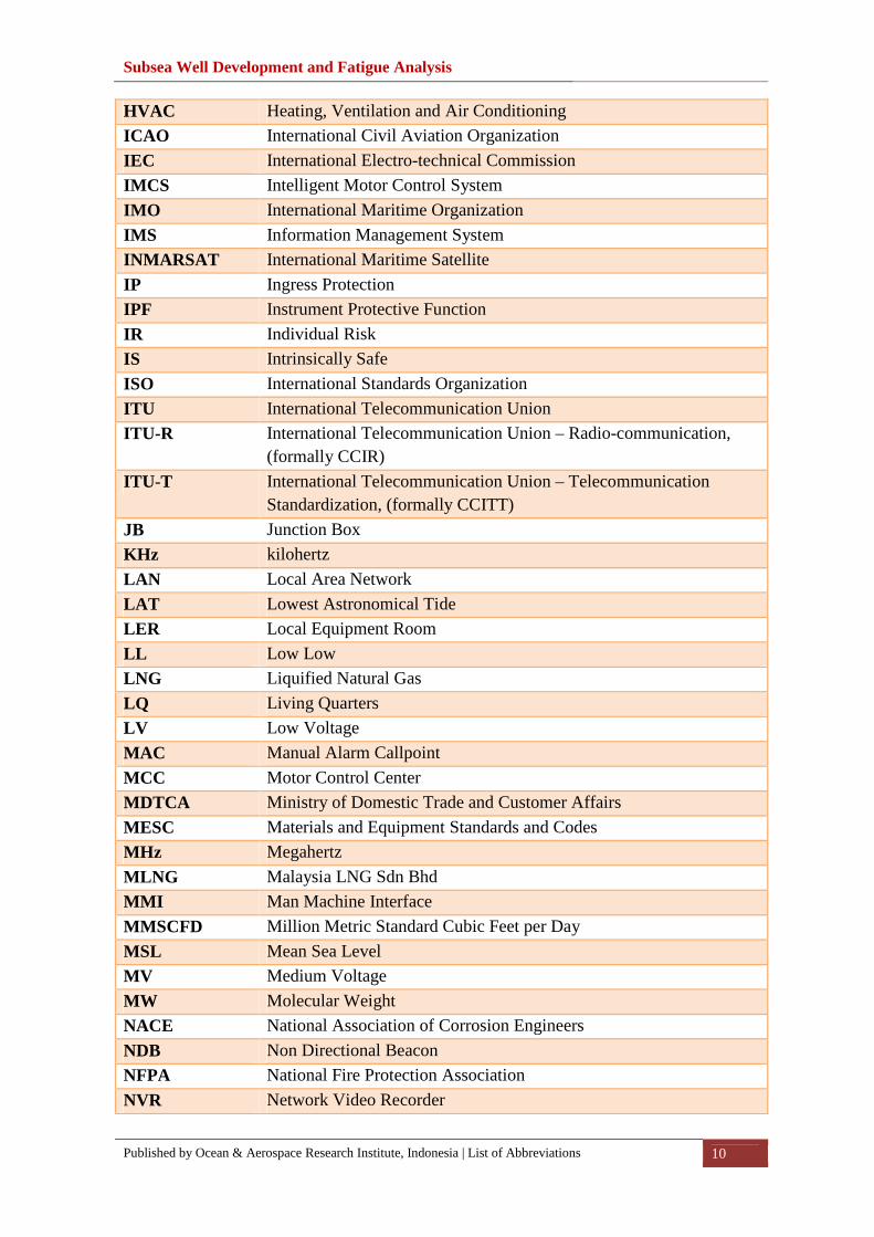
HVAC Heating, Ventilation and Air Conditioning
ICAO International Civil Aviation Organization
IEC International Electro-technical Commission
IMCS Intelligent Motor Control System
IMO International Maritime Organization
IMS Information Management System
INMARSAT International Maritime Satellite
IP Ingress Protection
IPF Instrument Protective Function
IR Individual Risk
IS Intrinsically Safe
ISO International Standards Organization
ITU International Telecommunication Union
ITU-R International Telecommunication Union – Radio-communication, (formally CCIR)
ITU-T International Telecommunication Union – Telecommunication Standardization, (formally CCITT)
JB Junction Box
KHz kilohertz
LAN Local Area Network
LAT Lowest Astronomical Tide
LER Local Equipment Room
LL Low Low
LNG Liquified Natural Gas
LQ Living Quarters
LV Low Voltage
MAC Manual Alarm Callpoint
MCC Motor Control Center
MDTCA Ministry of Domestic Trade and Customer Affairs
MESC Materials and Equipment Standards and Codes
MHz Megahertz
MLNG Malaysia LNG Sdn Bhd
MMI Man Machine Interface
MMSCFD Million Metric Standard Cubic Feet per Day
MSL Mean Sea Level
MV Medium Voltage
MW Molecular Weight
NACE National Association of Corrosion Engineers
NDB Non Directional Beacon
NFPA National Fire Protection Association
NVR Network Video Recorder
Subsea Well Development and Fatigue Analysis
Published by Ocean & Aerospace Research Institute, Indonesia | 11
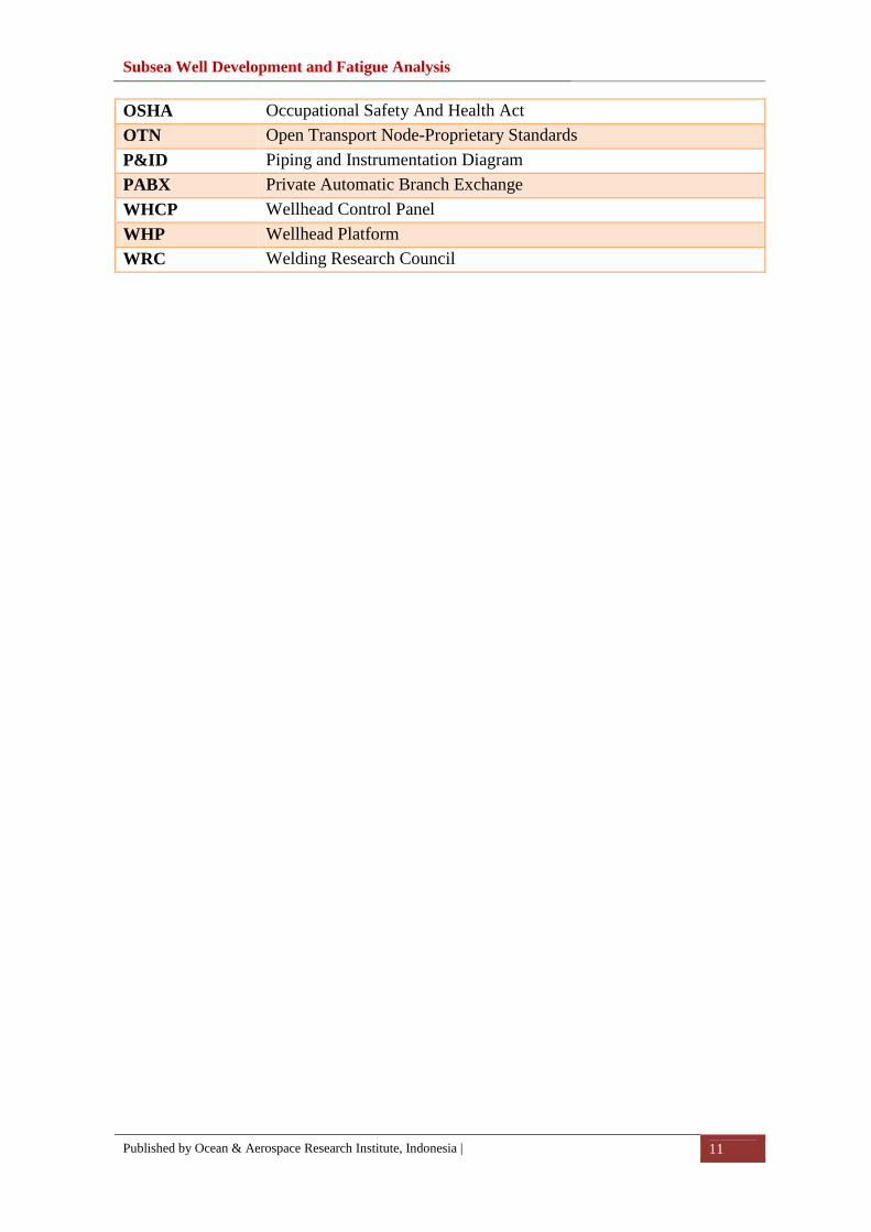
OSHA Occupational Safety And Health Act
OTN Open Transport Node-Proprietary Standards
P&ID Piping and Instrumentation Diagram
PABX Private Automatic Branch Exchange
WHCP Wellhead Control Panel
WHP Wellhead Platform
WRC Welding Research Council

Subsea Well Development and Fatigue Analysis
Published by Ocean & Aerospace Research Institute, Indonesia | List of Symbols 12
List of Symbols
Symbol Descriptions
A Added mass � Slope at free end
F Force
Subsea Well Development and Fatigue Analysis
Published by Ocean & Aerospace Research Institute, Indonesia | Table of Contents 13
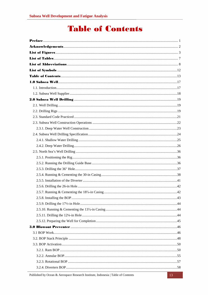
Table of Contents
Preface ......................................................................................................................................................... 1
Acknowledgements .................................................................................................................................. 2
List of Figures ........................................................................................................................................... 3
List of Tables ............................................................................................................................................. 7
List of Abbreviations .............................................................................................................................. 8
List of Symbols ........................................................................................................................................12
Table of Contents ....................................................................................................................................13
1.0 Subsea Well .......................................................................................................................................17
1.1. Introduction .........................................................................................................................................17
1.2. Subsea Well Supplier ..........................................................................................................................18
2.0 Subsea Well Drilling .....................................................................................................................19
2.1. Well Drilling .......................................................................................................................................19
2.2. Drilling Rigs .......................................................................................................................................19
2.3. Standard Code Practiced .....................................................................................................................21
2.3. Subsea Well Construction Operations ................................................................................................22
2.3.1. Deep Water Well Construction ....................................................................................................23
2.4. Subsea Well Drilling Specification .....................................................................................................24
2.4.1. Shallow Water Drilling ................................................................................................................25
2.4.2. Deep Water Drilling .....................................................................................................................26
2.5. North Sea’s Well Drilling ...................................................................................................................36
2.5.1. Positioning the Rig .......................................................................................................................36
2.5.2. Running the Drilling Guide Base .................................................................................................36
2.5.3. Drilling the 36" Hole ....................................................................................................................37
2.5.4. Running & Cementing the 30-in Casing ......................................................................................38
2.5.5. Installation of the Diverter ...........................................................................................................41
2.5.6. Drilling the 26-in Hole .................................................................................................................42
2.5.7. Running & Cementing the 18⅝-in Casing ...................................................................................42
2.5.8. Installing the BOP ........................................................................................................................43
2.5.9. Drilling the 17½-in Hole ..............................................................................................................44
2.5.10. Running & Cementing the 13⅜-in Casing .................................................................................44
2.5.11. Drilling the 12¼-in Hole ............................................................................................................44
2.5.12. Preparing the Well for Completion ............................................................................................45
3.0 Blowout Preventer .........................................................................................................................46
3.1 BOP Work............................................................................................................................................46
3.2. BOP Stack Principle ...........................................................................................................................48
3.3. BOP Activation ...................................................................................................................................50
3.2.1. Ram BOP .....................................................................................................................................50
3.2.2. Annular BOP ................................................................................................................................55
3.2.3. Rotational BOP ............................................................................................................................57
3.2.4. Diverters BOP ..............................................................................................................................58

Subsea Well Development and Fatigue Analysis
Published by Ocean & Aerospace Research Institute, Indonesia | Table of Contents 14
3.5. BOP in North Sea Operation ...............................................................................................................59
3.5. Control Methods .................................................................................................................................61
3.5.1. Shallow Water ..............................................................................................................................61
3.5.2. Deep Water ..................................................................................................................................62
4.0 Subsea Wellhead .............................................................................................................................63
4.1. Wellhead Casing Design .....................................................................................................................63
4.2. Wellhead Function Requirements .......................................................................................................65
4.3. Wellhead Operation Requirements .....................................................................................................66
4.4. Subsea Wellhead Components ............................................................................................................68
4.4.1. Casing Head .................................................................................................................................69
4.4.2. Casing Hanger ..............................................................................................................................70
4.4.3. Intermediate Casing Hanger .........................................................................................................71
4.4.4. Production Casing Hanger ...........................................................................................................72
4.4.3. Tubing Head ................................................................................................................................72
4.4.3. Tubing Hanger .............................................................................................................................72
4.4.4. Wellhead Housing ........................................................................................................................73
4.4.5. Lockdown Bushing ......................................................................................................................74
4.4.6. Metal-to-Metal Annulus Seal Assembly ......................................................................................75
4.4.7. Elastomeric Annulus Seal Assembly ...........................................................................................75
4.4.8. Running and Test Tools ...............................................................................................................75
4.4.9. Bore Protectors and Wear Bushings ............................................................................................80
4.4.10. Low-Pressure Wellhead Housing ...............................................................................................81
4.4.11. High-Pressure Wellhead Housing ..............................................................................................82
4.5. Casing Design: North Sea Operation ..................................................................................................83
4.6. Wellhead Guide Base System .............................................................................................................86
4.6.1. Temporary Guide Base ................................................................................................................86
4.6.2. Permanent Guide Base .................................................................................................................87
5.0 Subsea Well Completion ..............................................................................................................90
5.1. Subsea Well Completion Preparation .................................................................................................90
5.1.1. Open-Hole Well Completion .......................................................................................................91
5.1.2. Screen Completion .......................................................................................................................91
5.1.3. Casing or Liner Completion .........................................................................................................92
5.1. Subsea Test Tree .................................................................................................................................93
5.3. Subsea Well Testing ...........................................................................................................................93
5.3. Tubing String & Tubing Hanger Installation ......................................................................................94
5.4. Subsea Well Production Test ..............................................................................................................95
5.5. Cleaning up the Well ........................................................................................................................103
5.6. Suspending Subsea Well ...................................................................................................................103
6.0 Subsea Well Fatigue Analysis ..................................................................................................104
6.1. Wellhead Fatigue Analysis Process ..................................................................................................104
6.2.1. System Stack-up.........................................................................................................................107
6.2.2. Tensioning/Compensation Systems ...........................................................................................113
6.2.3. Upper Packages ..........................................................................................................................114

Subsea Well Development and Fatigue Analysis
Published by Ocean & Aerospace Research Institute, Indonesia | Table of Contents 15
6.2.4. Surface Equipment .....................................................................................................................114
6.2.5. Riser Joints .................................................................................................................................114
6.2.6. Flex Joints ..................................................................................................................................114
6.2.7. Lower Packages .........................................................................................................................115
6.2.8. Wellhead System .......................................................................................................................115
6.2.9. Casing System ............................................................................................................................116
6.2.10. Subsea Template Structure .......................................................................................................117
6.2.11. Soil Properties ..........................................................................................................................117
6.2.12. Environmental Conditions .......................................................................................................117
6.2. Simple Linear Elastic Model.............................................................................................................117
6.3. Static Wellhead Loading ...................................................................................................................122
6.4. Thermal Induced Loading .................................................................................................................123
6.5. Wellhead Reliability Analysis ..........................................................................................................123
7.0 Roncador Subsea Well System ................................................................................................130
7.1. Roncador Field ..................................................................................................................................130
7.2. Roncador Field Project Development ...............................................................................................131
7.3. Floating Structures in Roncador Field ..............................................................................................132
7.3.1. Brazil FPSO ...............................................................................................................................133
7.3.2. P-52 Submersible .......................................................................................................................134
7.4. Drilling System .................................................................................................................................136
7.5. Wellhead and Subsea Tree ................................................................................................................138
8.0 Perdido Subsea Well System ....................................................................................................142
8.1. Perdido Field .....................................................................................................................................142
8.1.1. Challenges and Issues ................................................................................................................142
8.1.2. Overcomes of Challenges ..........................................................................................................144
8.2. The Challenges .................................................................................................................................144
8.2.2. Development Challenges ...........................................................................................................145
8.2.3. Drilling Challenges ....................................................................................................................145
8.3. Field Layout System .........................................................................................................................148
8.3.1 DVA Cluster: ..............................................................................................................................149
8.3.2. Southwest Cluster ......................................................................................................................149
8.3.3. Oligocene Cluster (Frio Pilot) ....................................................................................................150
8.3.4. Regional Cluster (Silvertip and Tobago) ...................................................................................150
8.4. Subsea Facilities................................................................................................................................150
8.4.1. Surface BOP and Completion of Subsea Wells .........................................................................150
8.4.2. UWD-10 Slimbore .....................................................................................................................152
8.4.3. Chemical Injection .....................................................................................................................155
8.4.4. Subsea Boosting System ............................................................................................................155
9.0 NC3 Subsea Well System............................................................................................................159
9.1. NC3 Field ..........................................................................................................................................159
9.1.1 Selection Platform in Shallow Water .....................................................................................160
9.1.2 Design Life.............................................................................................................................161
9.1.3 NC3 Coordinates ....................................................................................................................161
Subsea Well Development and Fatigue Analysis
Published by Ocean & Aerospace Research Institute, Indonesia | 16
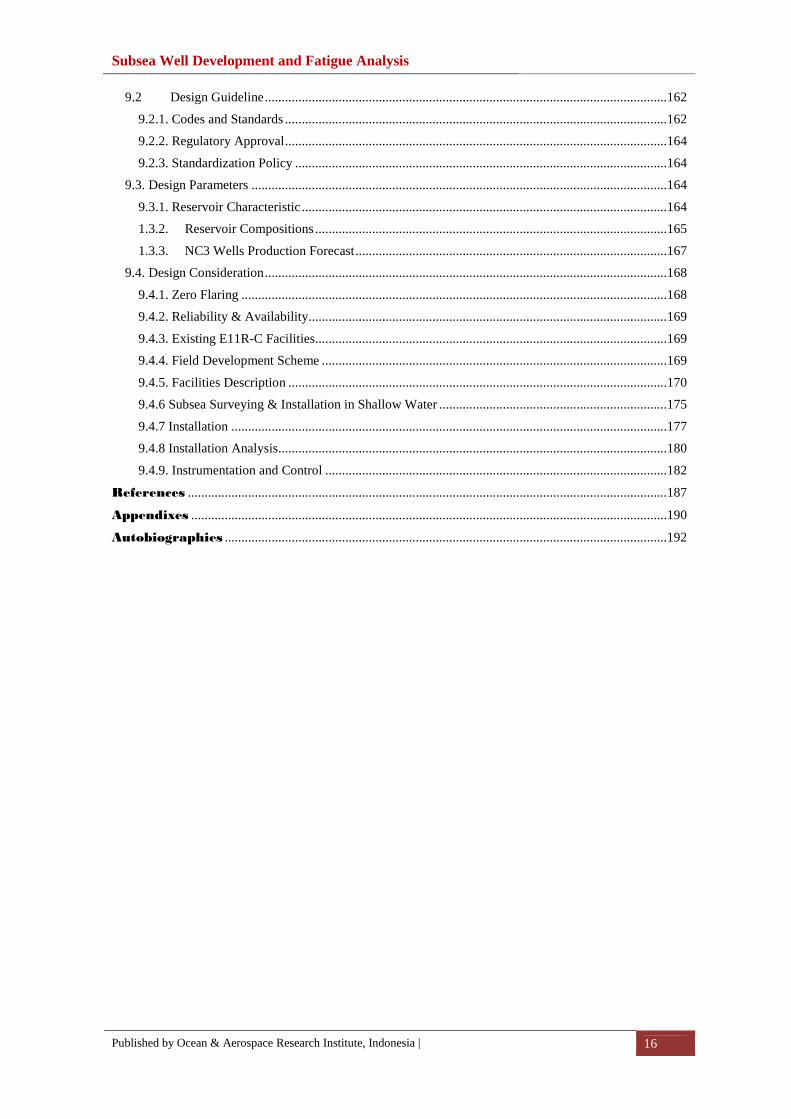
9.2 Design Guideline ........................................................................................................................162
9.2.1. Codes and Standards ..................................................................................................................162
9.2.2. Regulatory Approval ..................................................................................................................164
9.2.3. Standardization Policy ...............................................................................................................164
9.3. Design Parameters ............................................................................................................................164
9.3.1. Reservoir Characteristic .............................................................................................................164
1.3.2. Reservoir Compositions .........................................................................................................165
1.3.3. NC3 Wells Production Forecast .............................................................................................167
9.4. Design Consideration ........................................................................................................................168
9.4.1. Zero Flaring ...............................................................................................................................168
9.4.2. Reliability & Availability...........................................................................................................169
9.4.3. Existing E11R-C Facilities.........................................................................................................169
9.4.4. Field Development Scheme .......................................................................................................169
9.4.5. Facilities Description .................................................................................................................170
9.4.6 Subsea Surveying & Installation in Shallow Water ....................................................................175
9.4.7 Installation ..................................................................................................................................177
9.4.8 Installation Analysis ....................................................................................................................180
9.4.9. Instrumentation and Control ......................................................................................................182
References ...............................................................................................................................................187
Appendixes ..............................................................................................................................................190
Autobiographies ....................................................................................................................................192

Subsea Well Development and Fatigue Analysis
Published by Ocean & Aerospace Research Institute, Indonesia | Autobiographies 192
Autobiographies
Jaswar Koto was born on October, 1970. He is a descendant of the
Prophet Rasullullah S.A.W through Husein R.A. He is a President of
Ocean and Aerospace Research Institute, Indonesia. Professor on
offshore engineering and also President of International Society of
Ocean, Mechanical & Aerospace for scientist and engineers.
He has been invited as a Visiting Professor more than 16 times, received several
international awards and supervised PhD, Master and Bachelor Students.
He received his bachelor degree in 1994 from Institut Teknologi Sepuluh Nopember
(ITS), Indonesia, Curtin University in 1996 and Notre Dame University in 1999. In 2003
he has completed PhD with receiving award in engineering form Aerospace and Marine
Engineering, Osaka Prefecture University, Japan.
He has started his researches since 1994 on structure analysis of fluid flow in subsea
pipelines, subsea pipeline corrosion due to Carbon Monoxide, design and hydrodynamic
analysis of AUV in Australia. Then, he joined Research and Development Institute,
Sumitomo Heavy Industries -Marine Engineering-, Japan. In 2005, he joined ExxonMobil
projects. Since 2010, he has a contract with Department of Aeronautical, Automotive, and
Ocean Engineering, Faculty of Mechanical Engineering. He is also appointed as head of
High Performance Computing, CICT, Universiti Teknologi Malaysia.

Published by
Ocean & Aerospace Research Institute, Indonesia Pekanbaru-Riau, INDONESIA http://isomase.org/OCAri/Home.php
Edited by
Mechanical-Offshore Engineering, Universiti Teknologi Malaysia, MALAYSIA http://hpc.utm.my/
Supported by
International Society of Ocean, Mechanical & Aerospace - scientists & engineers – D/A: Resty Menara Hotel Jalan Sisingamangaraja No. 89 (28282), Pekanbaru-Riau INDONESIA http://www.isomase.org/
Deep Water & Offshore Indonesian Oil and Gas Community, INDONESIA