Embed Size (px)
Citation preview
41 150/118 ED 1/18
41 150/118 ED
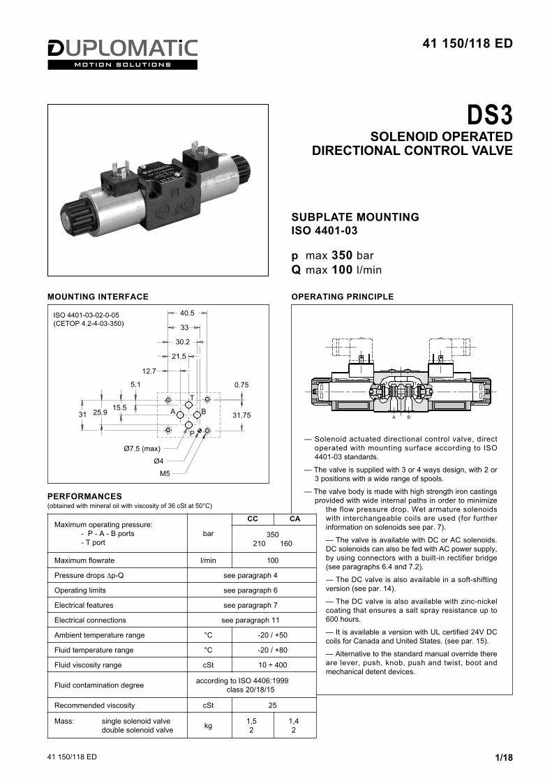
DS3SOLENOID OPERATED
DIRECTIONAL CONTROL VALVE
MOUNTING INTERFACE
ISO 4401-03-02-0-05(CETOP 4.2-4-03-350)
— Solenoid actuated directional control valve, directoperated with mounting surface according to ISO4401-03 standards.
— The valve is supplied with 3 or 4 ways design, with 2 or3 positions with a wide range of spools.
— The valve body is made with high strength iron castingsprovided with wide internal paths in order to minimize
the flow pressure drop. Wet armature solenoidswith interchangeable coils are used (for furtherinformation on solenoids see par. 7).
— The valve is available with DC or AC solenoids.DC solenoids can also be fed with AC power supply,by using connectors with a built-in rectifier bridge(see paragraphs 6.4 and 7.2).
— The DC valve is also available in a soft-shiftingversion (see par. 14).
— The DC valve is also available with zinc-nickelcoating that ensures a salt spray resistance up to600 hours.
— It is available a version with UL certified 24V DCcoils for Canada and United States. (see par. 15).
— Alternative to the standard manual override thereare lever, push, knob, push and twist, boot andmechanical detent devices.
OPERATING PRINCIPLE
SUBPLATE MOUNTINGISO 4401-03
p max 350 barQ max 100 l/min
Maximum operating pressure:- P - A - B ports- T port
bar
CC CA
350210 160
Maximum flowrate l/min 100
Pressure drops ∆p-Q see paragraph 4
Operating limits see paragraph 6
Electrical features see paragraph 7
Electrical connections see paragraph 11
Ambient temperature range °C -20 / +50
Fluid temperature range °C -20 / +80
Fluid viscosity range cSt 10 ÷ 400
Fluid contamination degree according to ISO 4406:1999 class 20/18/15
Recommended viscosity cSt 25
Mass: single solenoid valvedouble solenoid valve kg 1,5
21,42
PERFORMANCES(obtained with mineral oil with viscosity of 36 cSt at 50°C)

41 150/118 ED 2/18
DS31 - IDENTIFICATION CODE
Directional valve,solenoid operated
ISO 4401-03 size
Spool type (see paragraph 3)
DC power supplyD12 = 12 VD14 = 14 VD24 = 24 VD28 = 28 VD48 = 48 VD110 = 110 VD125 = 125 VD220 = 220 VD00 = valve without coils (see NOTE 1)
AC power supplyA24 = 24 V - 50 HzA48 = 48 V - 50 HzA100 = 100 V - 50 Hz / 100 V - 60 HzA110 = 110 V - 50 Hz / 120 V - 60 HzA230 = 230 V - 50 Hz / 240 V - 60 HzA00 = valve without coils (see NOTE1)F110 = 110 V - 60 HzF220 = 220 V - 60 Hz
Series: (the overall and mounting dimensions remainunchanged from 10 to 19)
Coil electrical connection(see par. 11): K1 = plug for connector type EN 175301-803 (ex DIN 43650) (standard)K2 = plug for connector type AMP JUNIOR (available on D12 and D24 coils only)K7 = plug DEUTSCH DT04-2P for maleconnector type DEUTSCH DT06-2S(available on D12 and D24 coils only)
Seals: N = NBR seals for mineral oil (standard)V = FPM seals for special fluids
D S 3 - / 11 - /
2 - HYDRAULIC FLUIDSUse mineral oil-based hydraulic fluids HL or HM type, according to ISO 6743-4. For these fluids, use NBR seals (code N). For fluids HFDR type(phosphate esters) use FPM seals (code V). For the use of other fluid types such as HFA, HFB, HFC, please consult our technical department.Using fluids at temperatures higher than 80 °C causes a faster degradation of the fluid and of the seals characteristics. The fluid must bepreserved in its physical and chemical characteristics.
Manual override:omit for override integrated in the tube(standard)CM = manual override, boot protected CH = lever manual override (only forDC version). The device is notavailable for TB, TB* and RSB* spools.RSA* spools: available only for RSA1and RSA2.CP = push manual override(only for DC version)CK1 = turning knob override (only for DC version)CK2 = push and twist knob override (only for DC version)CPK = push manual override withmechanical retention (only for DC version)
Option:/ W7 = Zinc-nickel surfacetreatment (see NOTE 2)Not available for AC valves.Omit if not required
S*SA*SB*
RSA*RSB*
TATBRSA*RSB*TA*TB*
RK
NOTE 2: The standard valve is supplied with surface treatment of phosphating black.The zinc-nickel finishing on the valve body makes the valve suitable to ensure a salt spray resistance up to 240 hours. For a salt spray resistance up to 600 hours refer to paragraph 17.(test operated according to UNI EN ISO 9227 standards and test evaluation operated according to UNI EN ISO 10289 standards).
NOTE 1: Coils locking ring and related OR aresupplied together with valves.

41 150/118 ED 3/18
DS33 - SPOOL TYPE
Type S*:2 solenoids - 3 positionswith spring centering
Type RSA*:1 solenoid side A 2 positions (external + central)with return spring
Type RSB*:1 solenoid side B 2 positions (external + central)with return spring
Type SA*:1 solenoid side A2 positions (central + external)with spring centering
Type SB*:1 solenoid side B2 positions (central + external)with spring centering
Besides the diagrams shown, which are the most frequently used, other special versionsare available: consult our technical department for their identification, feasibility andoperating limits.

41 150/118 ED 4/18
DS3
Type TA:1 solenoid side A 2 external positions with return spring
Type TB:1 solenoid side B 2 external positionswith return spring
Type TA*:1 solenoid side A 2 positions with return spring
Type TB*:1 solenoid side B 2 positions with return spring
Type RK:2 solenoids - 2 positionswith mechanical retention
Besides the diagrams shown, which are the mostfrequently used, other special versions are available:consult our technical department for theiridentification, feasibility and operating limits.

41 150/118 ED 5/18
DS3
DE-ENERGIZED POSITION
ENERGIZED POSITION
5 - SWITCHING TIMESThe values indicated are obtained according to ISO 6403 standard,with mineral oil viscosity 36 cSt at 50°C.
SPOOL TYPEFLOW DIRECTION
P→A P→B A→T B→TCURVES ON GRAPH
S1, SA1, SB1 2 2 3 3S2, SA2, SB2 1 1 3 3S3, SA3, SB3, RSA3, RSB3 3 3 1 1S4, SA4, SB4, RSA4, RSB4 5 5 5 5S5 2 1 3 3S6 2 2 3 1S7, S8 4 5 5 5S9 2 2 3 3S10 1 3 1 3S11 2 2 1 3S12, S17, S19 2 2 3 3S18 1 2 3 3S20, S22 1 5 2S21, S23 5 1 2 S28 6 5 - 6S29 5 6 6 -S59 3 3 - -TA, TB 3 3 3 3RTA 2 3 3 2RTB 3 2 2 3TA02, TB02 2 2 2 2TA23, TB23 3 3RK, RK02, RK1, 1RK 2 2 2 2
SPOOL TYPE
FLOW DIRECTION
P→A P→B A→T B→T P→T
CURVES ON GRAPH
S2, SA2, SB2 2S3, SA3, SB3, RSA3, RSB3 3 3S4, SA4, SB4, RSA4, RSB4 3S5 4S6 3S7, S8 6 6 3S10 3 3S11 3S18 4S22, S23 3 3S28, S29 6
4 - PRESSURE DROPS ∆p-Q (obtained with viscosity 36 cSt at 50 °C)
SPOOL TYPETIMES [ms]
ENERGIZING DE-ENERGIZINGCC 25 ÷ 75 15 ÷ 25 CA 10 ÷ 25 15 ÷ 40

41 150/118 ED 6/18
DS3
SPOOLCURVE
P→A P→BS1,SA1,SB1 1 1
S2, SA2, SB2 2 2
S3, SA3, SB3 3 3
S4, SA4, SB4 2 2
S5 5 5
S6 6 6
S7 4 4
S8 4 4
S9 7 7
S10 8 8
S11 6 6
S12 2 2
S17 7 7
S18 5 5
S19 7 7
S20 10* 10
S21 10 10*
S22 10* 10
S23 10 11*
S28
S29
S59
TA, TB 1 1
TA02, TB02 1 1
TA23, TB23 2 2
TA 30 5 -
RTA, RTB 11 11
RK 8 8
RK02 9 9
RK1, 1RK 8 8
6 - OPERATING LIMITSThe curves define the flow rate operating fields according to the valve pressure of the different versions. The values have been obtainedaccording to ISO 6403 norm with solenoids at rated temperature and supplied with voltage equal to 90% of the nominal voltage. The valuehave been obtained with mineral oil, viscosity 36 cSt, temperature 50 °C and filtration according to ISO 4406:1999 class 18/16/13.The limits for TA02 and TA spools refer to the 4-way operation. The operating limits of a 4-way valve in 3-way operation or with port A or Bplugged or without flow are shown in the chart on the next page. The performance of the DC solenoid powered by AC with rectifier connectorsare at par. 6.4. The performances of the soft-shift valve are shown at par. 14.
6.1 - Valves in standard operation
DC SOLENOID VALVE
* Performance obtained for a valve with A and B lines connectedthe one to the piston-side chamber and the other to the rod-sidechamber of a double-acting cylinder with area ratio 2:1.
SPOOLCURVE
P→A P→B
S1,SA1,SB1 1 1
S2, SA2, SB2 2 2
S3, SA3, SB3 3 3
S4, SA4, SB4 4 4
S5 5 5
S6 4 6
S7 4 4
S8 4 4
S9 7 7
S10 7 7
S11 4 6
S12 1 1
S17 4 4
S18 5 5
S19 4 4
S20 6* 6
S21 6 6*
S22 6 6
S23 6 6
S28 9* 9*
S29 9* 9*
S59 10 10
TA, TB 7 7
TA02, TB02 8 8
TA23, TB23 2 2
TA 30 1 -
RTA, RTB 11 11
RK 7 7
RK02 8 8
RK1, 1RK 7 7
DC SOLENOID VALVE AC SOLENOID VALVE
AC SOLENOID VALVE
RSA* SPOOLS AC AND DC
SPOOL CURVERSA1 12
RSA2 13
RSA3 14
RSA4 15

41 150/118 ED 7/18
DS3
6.3 - AC solenoid valve with coil A110 fed with 110V - 60 Hz
SPOOL CURVE
P→A P→B
S1,SA1, SB1 1 1
S2, SA2, SB2 2 2
S3, SA3, SB3 3 3
S4, SA4, SB4 4 4
S9 5 5
TA, TB 2 2
RK 6 6
6.2 - 4-way valve in 3-way operationOperating limits of a 4-way valve in 3-way operation or with port A or B plugged or without flow.
DC VALVE AC VALVE
SPOOL CURVE
DC AC
TA backpr. ATB backpr. B 1 1
TA02 backpr. ATB02 backpr. B 1 1
TA backpr. BTB backpr. A 2 1
TA02 backpr. BTB02 backpr. A 3 3
6.4 - Operating limits for DC solenoid valves fed with AC with rectifier connectors
SPOOLCURVE
P→A P→B
S1, SA1, SB1 2 2S2, SA2, SB2 3 3S3, SA3, SB3 4 4S4, SA4, SB4 2 2S9 5 5TA, TB 6 6RK 1 1

41 150/118 ED 8/18
DS37 - ELECTRICAL FEATURES
7.1 - SolenoidsThese are essentially made up of two parts: tube and coil. The tubeis threaded into the valve body and includes the armature thatmoves immersed in oil, without wear. The inner part, in contact withthe oil in the return line, ensures heat dissipation. The coil isfastened to the tube by a threaded ring, and can be rotated 360°, tosuit the available space.
Coils for alternating current (values ± 5%)
7.2 - Current and absorbed power for DCsolenoid valve The table shows current and power consumptionvalues of the DC coils.Using connectors type "D" (see cat. 49 000) withembedded bridge rectifier it is possible to feed DCcoils (starting from 48V voltage) with alternatingcurrent (50 or 60 Hz), considering a reduction ofthe operating limits (see diagram at section 6.4).
Coils for direct current (values ± 10%)
Nominalvoltage
[V]
Resistanceat 20°C
[Ω]
Currentconsumpt.
[A]
Powerconsumpt
[W]
Coil code
K1 K2 K7
D12 12 4,4 2,72 32,7 1903080 1903100 1902940
D14 14 7,2 1.93 27 1903086
D24 24 18,6 1,29 31 1903081 1903101 1902941
D28 28 26 1,11 31 1903082
D48 48 78,6 0,61 29,5 1903083
D110 110 423 0,26 28,2 1903464
D125 125 550 0,23 28,6 1903467
D220 220 1692 0,13 28,2 1903465
Protection from atmospheric agents IEC 60529The IP protection degree is guaranteed only with both valve andconnectors of an equivalent IP degree, correctly connected andinstalled.
NOTE: In order to further reduce the emissions, with DC supply,use of type H connectors is recommended. These prevent voltagepeaks on opening of the coil supply electrical circuit (see cat. 49 000).
SUPPLY VOLTAGE FLUCTUATION ± 10% Vnom
MAx SWITCH ON FREQUENCY 18.000 ins/hr
DUTY CYCLE 100%
ELECTROMAGNETIC COMPATIBILITY (EMC) (NOTE)
In compliance with2014/30/EU
LOW VOLTAGE In compliance with2014/35/EU
CLASS OF PROTECTION :Coil insulation (VDE 0580)Impregnation: DC valve AC valve
class Hclass Fclass H
Suffix
Nominal Voltage
[V]
Freq.
[Hz]
Resistance at 20°C
[Ω]
Currentconsumption
at inrush[A]
Currentconsumption
at holding[A]
Powerconsumption
at inrush[VA]
Powerconsumption
at holding[VA]
Coil Code
K1
A24 2450
1,69 5,81 1,32 139 32 1902830
A48 48 6,02 3,78 0,86 182 41 1902831
A100 100V-50Hz100V-60Hz
50/60
23,32,11 0,48 211 48
19028361,63 0,37 163 37
A110 110V-50Hz120V-60Hz 33
1,76 0,40 194 441902832
1,54 0,35 185 42
A230 230V-50Hz240V-60Hz 135
0,92 0,21 213 481902833
0,79 0,18 190 43
F110 11060
28,5 1,45 0,33 160 36 1902834
F220 220 103 0,92 0,21 203 46 1902835
7.3 - Current and absorbed power for AC solenoid valveThe table shows current and power consumption values at inrush and at holding, for AC coils.
electric connectionelectric
connectionprotection
wholevalve
protection
K1 EN 175301-803 (ex DIN 43650) IP65
IP65K2 AMP JUNIOR IP65/67
K7 DEUTSCH DT04 male IP65/67

41 150/118 ED 9/18
DS38 - OVERALL AND MOUNTING DIMENSIONS FOR DC SOLENOID VALVES
dimensions in mm
solenoid position for SB* , RSB*, TB and TB* configurations
DS3 - S*DS3 - RK
DS3-SA*, DS3-RSA*DS3-TA, DS3-TA*
1 Mounting surface with sealing rings:4 OR 2037 (9.25x1.78) - 90 shore
2 Standard manual override included in thesolenoid tube
3 Coil (360° revolving)
4 Coil removal space
5 EN 175301-803 (ex DIN 43650) connector To be ordered separately. See cat. 49 000
6 Connector removal space
7 Locking ring: tightening torque 5 ±0.5 Nm
Valve fastening: 4 SHC screws ISO 4762 M5x30
Tightening torque: 5 Nm (A8.8)
Threads of mounting holes: M5x10

41 150/118 ED 10/18
DS3
15653 232
87
47
47
46
56P
22.5
B
7365
211
1
75
A
11.2
T
B
P
7.5
A
4
7
54
9 - OVERALL AND MOUNTING DIMENSIONS FOR AC SOLENOID VALVES
solenoid position for SB*, RSB*, TB and TB* configurations
DS3 - S*DS3 - RK
DS3-SA*, DS3-RSA*DS3-TA, DS3-TA*
dimensions in mm
1 Mounting surface with sealing rings:4 OR 2037 (9.25x1.78) - 90 shore
2 Standard manual override included in thesolenoid tube
3 Coil (90° revolving)
4 Coil removal space
5 EN 175301-803 (ex DIN 43650) connector To be ordered separately. See cat. 49 000
6 Connector removal space
7 Locking ring: tightening torque 5 ±0.5 Nm
Valve fastening: 4 SHC screws ISO 4762 M5x30
Tightening torque: 5 Nm (A8.8)
Threads of mounting holes: M5x10

41 150/118 ED 11/18
DS310 - INSTALLATIONConfigurations with centering and return springs can be mounted in any position; type RK valves -without springs and with mechanical detent - must be mounted with the longitudinal axis horizontal.Valve fixing takes place by means of screws or tie rods, with the valve mounted on a lapped surface,with values of planarity and smoothness that are equal to or better than those indicated in the drawing.If the minimum values of planarity and/or smoothness are not met, fluid leakages between valve andmounting surface can easily occur.
Surface finishing
12 - ELECTRIC CONNECTORSSolenoid operated valves are delivered without connectors. Connectors type EN 175301-803 (ex DIN 43650) for K1 connections can beordered separately. See catalogue 49 000.
11 - ELECTRIC CONNECTIONS
connection for AMP JUNIORconnectorcode K2
connection forDEUTSCH DT06-2S male connector code K7
connection forDEUTSCH DT06-2S male connector code WK7 (W7 version only) code WK7D (W7 version only - coilwith diode)
connection for EN 175301-803(ex DIN 43650) connector code K1 (standard)code WK1 (W7 version only)
valv
e he
ight
valv
e he
ight
valv
e he
ight

41 150/118 ED 12/18
DS3
13.5 - CPK-DS3/10 Push manual override with mechanicalretention (only for DC solenoid valve)
13.3 - CP-DS3/10 Push manual override (only for DC solenoid valve)
Code: 3401150005
13.2 - CH-DS3/11 Lever manual override (only for DC solenoid valve)
Code: 3401150004
13 - MANUAL OVERRIDES
13.1 - Manual override, boot protected
Code: 3401150006
CM-DS3/11 - Version for DC solenoid valve Version for AC solenoid valve
Code: 0269201
13.4 - CK1-DS3/11 knob manual override, turning (only for DC solenoid valve)
A
P
118
110
50.5
27.552 ( version)SB
142 (coils 1 and 7D only)WK WK
NOTE: The lever device is alwayslocated in the A side of the valve. The high resistance to corrosionvalves (par. 17) are equipped with aboot for solenoid tube protection.
Code: 3401150021
13.6 - CK2-DS3/10 Push and twist manual override (only for DC solenoid valve)
Code: 3401150018

41 150/118 ED 13/18
DS3
Solenoid operated directionalcontrol valve
ISO 4401-03 size
DC power supplyD12 = 12 VD24 = 24 VD28 = 28 VD110 = 110 VD220 = 220 V
Series: (the overall and mounting dimensions remain unchangedfrom 10 to 19)
Soft-shifting
Manual override (see par.1 and 13)
Seals: N = NBR seals for mineral oil (standard)V = FPM seals for special fluids
D S 3 - / 13 - F/
14 - SOFT-SHIFT VERSION FOR DC VALVE
14.1 - Identification code
This version enables hydraulic actuators to perform a smooth startand stop by reducing the speed of movement of the valve spool.In this version, the S9 spool must be used instead of the S3 type.The diagram on the side shows the operating limits of the spoolsavailable in the soft-shifting version, while the table shows theswitching times. The values indicated are obtained according to ISO 6403 standard,with mineral oil viscosity 36 cSt at 50°C.The shifting time and characteristics curves are influenced by theviscosity (and thus by the temperature) of the operating fluid.Moreover, times can vary according to the flow rate and operatingpressure values of the valve. For correct operation of the soft-shifting ensure the solenoid tubesare always filled with oil. At this matter, we recommend to install abackpressure valve set at 1 ÷ 2 bar on T line.
Coil electrical connection(see par. 11): K1 = plug for connector type EN 175301-803 (ex DIN 43650) (standard)K2 = plug for connector type AMP JUNIOR (available on D12 and D24 coils only)K7 = plug DEUTSCH DT04-2P for maleconnector type DEUTSCH DT06-2S(available on D12 and D24 coils only)
SPOOL CURVETIMES [ms]
ENERGIZING DE-ENERGIZING
S1, S12 1 350 200 ÷ 300S2F 2 400 100 ÷ 250S4F 4 350 150 ÷ 300S9 1 400 200 ÷ 300TA12, TB12 3 180 200 ÷ 300TA23, TB23 300 200 ÷ 300
Option:/ W7 = see par. 1
Spool type The hydraulic symbols of S2F and S4F are identical tothose of S2 and S4 spools (p.2)
S1S2FS4FS9S12
TA12TB12TA23TB23

41 150/118 ED 14/18
DS3
Solenoid operated directionalcontrol valve
ISO 4401-03 size
Series:(the overall and mounting dimensions remainunchanged from 10 to 19)
Seals: N = NBR seals for mineral oil (standard)V = FPM seals for special fluids
Spool type See paragraph 3
15 - VERSION WITH UL CERTIFIED COILS
15.1 - Identification code
Power supply DC 24 V
LISK coil, UL certifiedto United States and Canada. Class 155 (F)
Coil electrical connectionfor connector type EN 175301-803(ex DIN 43650)
D S 3 - / 11 - D24 UL K1 /Manual override:omit for override integrated in the tube (standard)CM = manual override, bootprotected
Nominalvoltage
[V]
Resistanceat 20°C
[Ω]
Currentconsumpt.
[A]
Powerconsumpt
[W]
Coil code
D24ULK1 24 19.2 1.25 30 1903341
15.3 - Electrical features(values ± 10%)
15.2 - UL file numberThe UL database website provides informations about thecertification, by entering the code MH29222 in the 'UL filenumber' field.
15.4 - Overall and mounting dimensions
NOTE: Valves with UL coils must be ordered complete. The UL coils arenot interchangeable with those of standard valves.
dimensions in mm
1 Standard manual override included in thesolenoid tube
2 CM version:boot manual ovverride, rubber
Valve fastening: 4 SHC screws ISO 4762 M5x30
Tightening torque: 5 Nm (A8.8)
Threads of mounting holes: M5x10

41 150/118 ED 15/18
DS3
Fastening screws interchangeablewith Rexroth 4WE6*6X valve.
16 - VERSION WITH FIxING INTERCHANGEABLE WITH 4WE6*6x RExROTH
16.1 - Identification code
Directional valve,solenoid operated
ISO 4401-03 size
Spool type (see paragraph 3)
Series: (the overall and mounting dimensions remain unchanged from10 to 19)
Complete the indentification codeconfiguration as for in paragraph 1.
D S 3 R - / 11
S*SA*SB*
RSA*RSB*
TATBTA*TB*
RK
- /
16.2 - Overall and mounting dimensions for DC solenoid valves
dimensions in mm
Valve fastening: 4 SHC screws ISO 4762 M5x50
Tightening torque: 5 Nm (A8.8)
Threads of mounting holes: M5x10
16.3 - Overall and mounting dimensions for AC solenoid valves
dimensions in mm
Valve fastening: 4 SHC screws ISO 4762 M5x50
Tightening torque: 5 Nm (A8.8)
Threads of mounting holes: M5x10
Please refer to the standard valve atparagraph 8 for non-quoted dimensions.
Please refer to the standard valve atparagraph 9 for non-quoted dimensions.

41 150/118 ED 16/18
DS3
Solenoid operated directionalcontrol valve
ISO 4401-03 size
Series: (See paragraph 1 or 14)(the overall and mounting dimensions remainunchanged from 10 to 19)
Seals: N = NBR seals for mineral oil (standard)V = FPM seals for special fluids
Spool type See paragraph 3 or 14.
17 - HIGH IP AND CORROSION RESISTANCE VERSION
17.1 - Identification code
DC power supplyD12 = 12 VD24 = 24 VD26 = 26.4 V
Coil electrical connection (see par. 11)WK1 = plug for connector type EN 175301-803(ex DIN 43650)WK7 = plug DEUTSCH DT04-2P, for maleconnector type DEUTSCH DT06-2S. WK7D = plug DEUTSCH DT04-2P, for maleconnector type DEUTSCH DT06-2S. Coil with diode. (not available for coil D26)
D S 3 - / - / / W7Manual override:CM = manual override, boot protected(standard) CH = lever manual overrideCP = push manual overrideCK1 = turning knob overrideCK2 = push and twist knob(only for DC version)CPK = push manual override withmechanical retention
17.2 - Corrosion resistanceThis version features the zinc-nickel coating on all exposed metal parts of the valve,making it resistant to exposure to the salt spray for 600 hours (test performed accordingto UNI EN ISO 9227 and assessment test performed according to UNI EN ISO 10289).
17.3 - DC coilsThe coils feature a zinc-nickel surface treatment. The WK7D coil includes a suppressor diode of pulses for protection from voltage peaksduring switching. During the switching the diode significantly reduces the energyreleased by the winding, by limiting the voltage to 31.4V in the D12 coil and to 58.9 V inthe D24 coil.
(values ±10%)
Nominalvoltage
[V]
Resistanceat 20°C
[Ω]
Currentconsumpt.
[A]
Powerconsumpt
[W]
Coil code
WK1 WK7 WK7D
D12 12 4,4 2,72 32,7 1903590 1903580 1903600
D24 24 18,6 1,29 31 1903591 1903581 1903601
D26 26,4 21,8 1,21 32 1903599 1903589 -
17.4 - Protection from atmospheric agents IEC 60529The IP protection degree is guaranteed only with both valve and connectors of anequivalent IP degree, correctly connected and installed.
electric connection electric connectionprotection
whole valveprotection
WK1 EN 175301-803 (ex DIN 43650) IP66 IP66
WK7 DEUTSCH DT04 male IP66/IP68/IP69IP69K*
IP66/IP68/IP69IP69K*
WK7D DEUTSCH DT04 male IP66/IP68/IP69IP69K*
IP66/IP68/IP69IP69K*
(*) The IP69K protection degree is not taken into account in IEC 60529 but it is includedin ISO 20653.
NOTE: As regards the liquid ingress protection(second digit), there are three means ofprotection. Codes from 1 to 6 are related to water jets. Rates 7 and 8 are related to immersion. Rate 9 is reserved for high pressure andtemperature water jets. This means that IPX6 covers all the lower steps,rate IPX8 covers IPX7 but not IPX6 and lower,instead IPX9 does not cover any of them. Whether a device meets two types of protectionrequirements it must be indicated by listing boththe tests separated by a slash.(E.g. a marking of an equipment covered bothby temporary immersion and water jets isIP66/IP68).

41 150/118 ED 17/18
DS3
Supply voltageD12 = 12 VD14 = 14 VD24 = 24 VD26 = 26.4 VD28 = 28 VD48 = 48 VD125 = 125 VD110 = 110 VD220 = 220 V
Series no.: 10 = for K7 and WK7 11 = for K1 up to D48 and K2 12 = for K1 D110, D125, D220,WK1 and WK7D
19 - SPARE PARTS FOR DC SOLENOID VALVE
SEALS KITThe codes include the O-Ring n° 2, 5, 6 e 7.Cod. 1985406 NBR sealsCod. 1985410 FPM (viton) seals
DC COILS AND ELECTRICAL CONNECTORSIDENTIFICATION CODE
1 Coil locking ring with seal included cod. 0119412Tightening torque 5 ±0.5 Nm
2 ORM type 0220-20 (22x2) - 70 Shore
3 Coil (see identification code)
4 Solenoid tube for standard version:TD22-DS3/10N (NBR seals)TD22-DS3/10V (FPM seals)Solenoid tube for version with soft-shifting:TD22-DS3F/10N (NBR seals)TD22-DS3F/10V (FPM seals)NOTE: OR n°5 included
5 OR type 2062 (15.6x1.78) - 70 Shore
6 4 OR type 2037 (9.25x1.78) - 90 Shore
7 For coils WK* only: ORM-0220-20 - MVQ
22S3C - /
18 - PORT RESTRICTORSPort restrictors are recommended if f lowvariations which exceed the valve performancelimit during the switching processes occur, or forcircuit dampening. Port restrictor plugs can be ordered separatelywith the part numbers shown at left.
Ø (mm) part numberblank 01441620.6 01441630.8 01440331 0144034
Ø (mm) part number1.2 01440351.5 01440361.8 01441642 0144165
NOTE: You can also order coils using the coil codesin paragraphs 7.2 and 17.3.
Coil electrical connection (see par. 11): K1 = plug for connector EN 175301-803 (ex DIN 43650) for coils D12, D24 and D26:WK1 = plug for connector EN 175301-803 (ex DIN 43650) WK7 = plug DEUTSCH DT04-2P, for maleconnector type DEUTSCH DT06-2S.Only for D12 and D24:K2 = plug for connector AMP JUNIORK7 = plug DEUTSCH DT04-2P, for maleconnector type DEUTSCH DT06-2S.WK7D = plug DEUTSCH DT04-2P, for maleconnector type DEUTSCH DT06-2S.Coil with diode.
41 150/118 ED 18/18
DS3
REPRODUCTION IS FORBIDDEN. THE COMPANY RESERVES THE RIGHT TO APPLY ANY MODIFICATIONS.
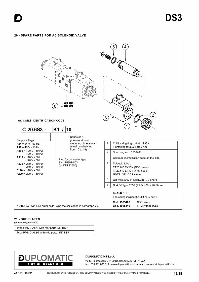
Type PMMD-AI3G with rear ports 3/8” BSP
Type PMMD-AL3G with side ports 3/8” BSP
21 - SUBPLATES (see catalogue 51 000)
Supply voltageA24 = 24 V - 50 HzA48 = 48 V - 50 HzA100 = 100 V - 50 Hz 100 V - 60 HzA110 = 110 V - 50 Hz 120 V - 60 HzA230 = 230 V - 50 Hz 240 V - 60 HzF110 = 110 V - 60 HzF220 = 220 V - 60 Hz
Plug for connector typeEN 175301-803 (ex DIN 43650)
Series no.: (the overall andmounting dimensionsremain unchangedfrom 10 to 19)
20 - SPARE PARTS FOR AC SOLENOID VALVE
SEALS KIT The codes include the OR nr. 5 and 6.
Cod. 1985406 NBR sealsCod. 1985410 FPM (viton) seals
AC COILS IDENTIFICATION CODE
20.6S3C - K1 / 10
1 Coil locking ring cod. 0119333Tightening torque 5 ±0.5 Nm
2 Snap ring cod. 0550483
3 Coil (see identification code on the side)
4 Solenoid tube :TA20.6-DS3/10N (NBR seals)TA20.6-DS3/10V (FPM seals)NOTE: OR n° 5 included
5 OR type 2062 (15.6x1.78) - 70 Shore
6 N. 4 OR type 2037 (9.25x1.78) - 90 Shore
NOTE: You can also order coils using the coil codes in paragraph 7.3