Embed Size (px)
Citation preview

1
SUBMITTED BY
James Collingsworth│Colten Leach│Konner Kay│Skyler Sheperd│Trey Minton
Charles Machine Works - Ditch Witch
December 2nd, 2016.

2
Table of Contents
1. Abstract (pg. 6)
2. Statement of Work (pg. 6)
3. Deliverables (pgs. 6 – 7)
4. Work Breakdown Structure (pg. 7- 9)
4.1. Project Overview (pg. 7)
4.1.1. Introduction (pg. 7)
4.1.2. Problem Statement (pg. 7)
4.1.3. Customer Requirements (pg. 7)
4.1.4. Proposed Solution (pg. 7)
4.2. Documentation and Procedures (pg. 7)
4.2.1. Ditch Witch Trailer Research (pg. 7)
4.2.2. Patent Search (pg. 7)
4.2.3. Conceptual Drawings (Solidworks, Freehand) (pgs. 7 - 8)
4.3. Client Approval (pg. 8)
4.3.1. Client Design Review (pg. 8)
4.4. Fabrication of Lift Axle (pg. 8)
4.4.1. Materials Required for Production (pg. 8)
4.4.2. Fabrication (pg. 8)
4.4.3. Install Lift Axle (pg. 8)
4.5. Integration of Remote Control (Spring Semester) (pg. 8)
4.5.1. Install Control Modules (pg. 8)
4.5.2. Analyze Diagnostics (pg. 8)

3
4.5.3. Functional Check of Controls (pg. 9)
4.5.3.1. Figure 1. Task List for Fall Semester (pg. 9)
5. Introduction (pgs. 9 - 10)
5.1. Figure 2. FX-30 in the Field (pg. 10)
5.2. Figure 3. Hendrickson Steerable Lift Axle (pg. 10)
6. Technical Literature Review (pgs. 11 - 16)
6.1. Figure 4. FX-30 Front View (pg. 11)
6.2. Figure 5. FX-30 Back View (pg. 12)
6.3. Table 1. FX-30 Trailer Dimensions (pg. 12)
6.4. Table 2. Power (pg. 13)
6.5. Table 3. Hydraulic System (pg. 13)
6.6. Figure 6. Haulle Tug (pgs.13 - 14)
6.7. Figure 7. MUV 4WD Electric Tug (pgs. 14 - 15)
7. Patent Searches (pgs. 16 - 20)
7.1. Compact Multipurpose Trailer Tug (pgs. 16 - 17)
7.1.1. Figure 8. Trailer Tug Apparatus (pg. 16)
7.1.2. Figure 9. Tug/Remote Specifications (pg. 17)
7.2. Tugbot (pgs. 17 - 18)
7.2.1. Figure 10. Tugbot Remote Control (pg. 17)
7.2.2. Figure 11. Tugbot Design (pg. 18)
7.3. Drive Unit for Trailers and Caravans (pgs. 18 - 19)
7.3.1. Figure 12. Drive Unit (pg. 18)
7.3.2. Figure 13. Drive Unit Attachment Assembly (pg. 19)

4
7.4. Wheelchair Drive System with Ratchet and Wheel Lock (pg. 19)
7.4.1. Figure 14. Wheelchair Drive System Specs (pg. 19)
7.5. Axle Lift (pg. 20)
7.5.1. Figure 15. Axle Lift (pg. 20)
8. Methodology (pgs. 21 - 22)
8.1. Table 4. Trailer Specifications (pg. 21)
8.2. Table 5. HP Requirement per Degree of Slope (pg. 22)
9. Safety Considerations (pgs. 22 - 23)
10. Sustainability Characteristics (pg. 23)
11. Customer Requirements (pg. 24)
12. Engineering Specifications (pgs. 24 - 25)
12.1. Figure 16. Free Body Diagram of FX-30 (pg. 24)
12.2. Figure 17. Law of Cosines of Piston (pg. 26)
12.3. Table 6. Piston Length Data (pg. 27)
12.4. Table 7. Support Arm Strength Data (pg. 27)
12.5. Table 8. Axle Strength (pg. 28)
13. Preliminary Design Concepts (pgs. 28 - 31)
13.1. “Segway” Tug (pg. 28)
13.1.1. Figure 18. “Segway” Tug (pg. 28)
13.2. Chain and Sprocket Drive (pgs. 29 - 29)
13.2.1. Figure 19. Chain and Sprocket Drive (pg. 29)
13.2.2. Figure 20. Chain and Sprocket Assembly (pg. 29)
13.3. Drive Motor on Wheel Hubs (pg. 30)

5
13.3.1. Figure 22. Dive Motor System (pg. 30)
13.4. Ratcheting Drive System (pgs. 30 - 31)
13.4.1. Figure 23. Ratcheting Drive Axle Top View (pg. 30)
13.4.2. Figure 24. Ratcheting Drive Axle Side View (pg. 31)
14. Final Design Concepts (pgs. 31 - 33)
14.1. Figure 25. Trailer Front View (pg. 31)
14.2. Figure 26. Trailer Top View (pg. 32)
14.3. Figure 27. Drive Axle (pg. 32)
14.4. Figure 28. Steer Axle (pg. 33)
14.5. Figure 29. Steer Axle Mounting (pg. 33)
15. BAE Freshman Involvement (pg. 34)
16. Summary (pgs. 34 - 35)
17. Project Schedule (pgs. 35 - 36)
14.6. Figure 30. Project Schedule (pgs. 35 - 36)
18. Proposed Budget (pg. 36)
19. Appendix (pgs. 37 - 41)
20. References (pgs. 42 – 43)

6
Abstract
The objective of this project is the development of a system for Charles Machine
Works, that will enable the FX-30 vacuum excavator to move without the use of a
standard motorized vehicle. The design must meet the following parameters (as
specified by Ditch WitchTM): operate on hard surfaces, self-propelled, must be stowed
on the trailer, operated by a remote control and the top speed achieved should be 1 – 1
¼ mph. The design will handle hard surfaces such as, pavement, gravel, asphalt and
hard ground. It is not designed for mud, or sand. The design must have its own
mechanism for braking, or utilize the existing trailer brakes. In addition, it could
incorporate both braking systems together as a design failsafe. The remote control
system can be tethered or wireless, it was not specified which the client preferred. The
top speed achieved will be a slow walking pace.
Statement of Work
This project will consist of designing and fabricating a system that will maneuver
the FX-30 Vacuum Trailer on hard pavement at a slow speed (1 - 1 ¼ mph). The FX-30
Trailer that the team are designing for will be provided to Oklahoma State University by
Charles Machine Works – Ditch WitchTM. The students will perform the testing of their
design on the trailer at Oklahoma State University. The fabrication for the design will be
done at OSU and at Ditch WitchTM as needed.
The overall objective of this project is to improve the FX-30 Vacuum Trailer by
allowing it to move without a vehicle. The data that will be collected through testing will
measure the amount of HP needed to move the trailer, how much torque produced, max
gradient the trailer can climb, effectiveness on different terrain and which design
performs better (hydraulics, ratcheting, electric motor).
Deliverables
1) Conceptual Design of the System
2) Fabrication and integration of the design onto the FX-30
3) Testing procedures and experimental data collection.
4) Results and Summary of completed design

7
5) Final Report
Work Breakdown Structure
WBS 1.0 Project Overview
Details the contents of the project and its purpose. Work is complete after meeting with
the client and receiving the approval for the proposed solution.
WBS 1.1 – Introduction
Work with Charles Machine Works, Ditch WitchTM to develop a design that
correlates to their problem statement. Task is complete once a general overview
of what the client expects is completed.
WBS 1.2 – Problem Statement
Analyzing and interpreting the client’s desires to ensure the project is developed
to meet their needs. Task is complete once the problem statement is well
defined.
WBS 1.3 – Customer Requirements
Communicate with the client to ensure that the final product produced meets their
expectations. Task is complete after the client specifies what the intended
product must do.
WBS 1.4 – Proposed Solution
Meet with Ditch WitchTM to discuss the design. Task is complete when the
conceptual design is proposed to the client and an approval is given.
WBS 2.0 Documentation and Procedures
Research relevant patents and documents that correlate to the design. Work is
complete once all of the documentation and procedures have been sorted for relevance
and organized accordingly in a word file.
WBS 2.1 Ditch Witch Trailer Research
Utilize Ditch WitchTM’s website to find trailer specifications. Task is complete once
the trailer specifications have been documented.
WBS 2.2 Patent Search
Find relevant patents that could potentially be utilized in the design. Task is
complete after the patents are cited and documented.
WBS 2.3 Conceptual Drawings (Solidworks, Freehand)

8
Produce drawings for the trailer drive system. Task is complete when the
drawings are finished.
WBS 3.0 Client Approval
Meet with the client and discuss the proposed system for the trailer. Work is complete
once the client approves the design.
WBS 3.1 Client Design Review
Discuss the system with the client by way of drawings, calculations,
documentation. Task is complete once the client approves of the proposed
concept.
WBS 4.0 Fabrication of Lift Axle
Fabricate and install the Lift Axle onto the FX-30 Trailer. Work is complete once the lift
axle has been fabricated and mounted to the trailer.
WBS 4.1 Materials Required for Production
Gather materials needed to begin fabricating the system. Task is complete once
all the parts for the design have been collected.
WBS 4.2 Fabrication
Talk with Ditch WitchTM and the BAE lab to begin fabricating parts needed to
complete the system. Task is complete once all the parts needed have been
produced.
WBS 4.3 Install Lift Axle
Work with Ditch WitchTM to install the lift axle onto the FX-30 Trailer. Task is
complete once the lift axle is mounted to the trailer.
WBS 5.0 Integration of Remote Control (Spring Semester)
Install and mount the control modules onto the Lift Axle. Work is complete once the
system is fully functional.
WBS 5.1 Install Control Modules
Install control modules onto the wheel hubs and wire in the components. Task is
complete once the control modules are fully functional.
WBS 5.2 Analyze Diagnostics
Install any remaining components that may be necessary for the system to steer,
drive and brake. Task is complete once the trailer is able to steer, drive and
brake.

9
WBS 5.3 Functional Check of Controls
Perform checks on all the systems on the trailer to ensure they are working
properly. Task is complete once the systems have been verified to be working.
The Statement of Work and WBS can be seen collectively in Figure 1, Team Trot’n
trailer’s task list.
Figure 1. Task List for Fall Semester.
Introduction
Ditch WitchTM is an innovative company with a focus on the development of
machinery that enable their customers to work more efficiently. Ditch WitchTM produces
various types of equipment such as: trenchers, directional drills, skid steers, and
vacuum excavators. In addition, Ditch WitchTM is always striving to further develop and
improve their existing products.
The Senior Design Team was tasked to develop an innovative way to move the
FX-30 excavator trailer at a slow speed of approximately (1 mph) on hard pavement, (as
specified by Ditch WitchTM) without the use of a standard motorized vehicle. The FX-30
excavator trailer can be seen in Figure 2.

10
Figure 2. FX-30 vacuum excavator in the field.
The vacuum excavators are used in many applications such as: exposing buried
utility lines, cleaning out storm drains, directional drilling site cleanup, water leak repair,
valve box cleanout, utility vault cleanout, commercial and residential debris cleanup and
landscaping, and posthole digging. The team researched methods for towing large
objects such as: airplanes, boats, trailers, etc. The most common method for moving
large objects without the use of a truck is by way of a trailer tug. However, after meeting
with our client, a trailer tug is not a viable solution. The client specified product must
enable their trailers to move independently and not be restricted to movement only by a
vehicle. The team brainstormed possible alternatives to move the trailer. The final
design will consist of adding a lift axle on the front of the trailer and another behind the
rear axle. An example of a lift axle can be seen in Figure 3.
Figure 3. Hendrickson Steerable Lift Axle.

11
The lift axle attached on the front of the trailer will be used for steering and the back-
rear axle will be the drive. By modifying the trailer and installing a drivable and steerable
lift axle, the trailer can move freely without a standard motorized vehicle. Currently, the
team is further developing the design to ensure exceedance of Ditch WitchTM’s
expectations. By implementing these modifications to Ditch WitchTM’s existing products,
Ditch WitchTM will generate more income, because the product is convenient for the
consumers.
Technical Literature Review
The FX-30 is the trailer that the team will be utilizing for their design with Ditch
WitchTM. The trailer itself can be seen in Figures 4 and 5.
Figure 4. FX-30 trailer front view.

12
Figure 5. FX-30 back view.
The design specifications for the FX-30 were provided by Ditch WitchTM and can
be seen in Tables 1-3.
Table 1. FX-30 Trailer Dimensions

13
Table 2. Power
Table 3. Hydraulic System
As of currently, there are hundreds of trailer tugs on the market. The team chose
a few that were the most relevant to their design. For example, the Haulle trailer tug
(seen in Figure 6) has a similar design concept.

14
Figure 6. Haulle Tug
The Haulle is used for a variety of trailers ranging from: boat, yard, and highway
trailers. It is rated for 40,000 lb towing capacity and it can hold up to 15,000 lb tongue
weight. The tug is equipped with a wireless remote to maneuver, but it also has built in
manual controls in case the remote fails. It is equipped with the following features:
hydraulic lift, brakes, heavy duty steel, safety stop switches. However, some
disadvantages to this product are: 24 hp gas engine, on-board hydraulic pump, 10
wheels, costly design, cannot fit onto trailer. The maintenance costs associated with this
design are: hydraulic lines, tires, batteries for the remote, hydraulic rams, drive chain
and belts. Similarly, to that of the Haulle, the MUV 4WD is a remote controlled electric
tug (seen in Figure 7).
Figure 7. MUV 4WD Electric Tug

15
The MUV tug is powered by two 440W, 24V DC with two x 125A programmable
motor controllers. It is equipped with a built-in battery charger, master key switch
(on/off), battery gauge and safety devices such as an LED strobe and motion beeper.
The disadvantage associated with this tug is its limited power capacity.
Trailer tugs are made out of high grade steel in order to withstand the weight of a
fully loaded trailer. The frame is durable and requires hardly any maintenance. The tires
on the tug require the most maintenance. Depending on the quality of the tire and the
load being applied, the tires may need replacing often. It is dependent on how often the
trailer caddy is used. The cost for a tire ranges from $20-$40 depending on the quality.
The battery life span on electrically powered tugs depends on how often the tug is used.
The average life span of a battery is 2-5 years and the cost ranges from $50-$150.
Hydraulically powered tugs have more maintenance costs and requirements due to the
hydraulic lines, fluid, and pump. Hydraulic lines can bust often if the pressure is too high
or the line has a flaw. The cost of hydraulic lines on average is $2 per foot. If a line does
break, the hydraulic fluid lost needs to be replaced and costs $5 per gallon. The
hydraulic pump needs little maintenance as long as the pump does not run dry. The
average cost of a pump is $200. If the tug is fitted with a wireless remote control, the
remote just needs to be recharged every 12 hours.
The majority of trailer tugs are either electrical or manually powered. A
characteristic that is not used as often is hydraulic powered tugs. This is because most
tugs don’t have access to a hydraulic pump. If a tug is hydraulic powered, it is usually a
large machine that has enough room to be fitted with a motor, pump, and hydraulic
reservoir if they are to be self-sustaining. In other cases, they are ran from an existing
pump on a trailer and are limited to trailers that have pumps. Another characteristic that
is not used as often is being able to control the tug by a remote control. Most tugs are
maneuvered manually by the operator. This is because the cost of a remote is higher
and implementing it into the tug is more difficult than using handles.

16
The major safety concerns with trailer tugs is being able to stop the unit,
particularly when moving downhill. In addition, if the product is used within a warehouse
it should be equipped with a horn and siren to alert civilians that may be in the premise.
Patent Searches
Compact Multipurpose Trailer Tug (Patent # US 6758291 B1, July 6, 2004).
This patent was chosen because the said device attaches to the tongue of the
trailer and can pivot due to two hydrostatic motors like a skid steer.
In addition, a model of the design can be seen in Figures 8 and 9. See Appendix i. for
patent claims.
Figure 8. Trailer Tug apparatus.

17
Figure 9. Tug/Remote Specifications.
Tugbot (Patent # US 20120215393 A1, August, 23rd, 2012).
This invention is a similar concept to that of our own, and it also utilizes a remote
control for steering the device. The claims described by the patent are as described in
Table 5. The design specifications for the Tugbot can be seen in Figures 10-11. See
Appendix ii. for patent claims.
Figure 10. Tugbot Remote Control.

18
Figure 11. Tugbot Design
Drive Unit for Trailers and Caravans (Patent # US 20090308667 A1, December 17th,
2009).
This tug is operated entirely via electric power and is equipped with a remote
control. In addition, the team is considering using tracks instead of tires, but this is yet to
be determined. The following claims provided in Table 6 correlate to the teams’ design
that is under speculation and the design of the tug cited can be seen in Figures 12-13.
See Appendix iii. for patent claims.
Figure 12. Drive Unit

19
Figure 13. Drive Unit Attachment Assembly
Wheelchair drive system with ratchet and wheel lock (Patent # US 5743544 A, April
28th, 1998)
This invention utilizes a ratchet driven wheel that propels the wheel chair. This
could be applied to a trailer by adding a hydraulic piston mounted on the trailer frame to
engage the ratchet assembly mounted on either an axle or on a wheel. See Appendix
iv. for patent claims.
Figure 14. Wheelchair Drive System Specs

20
Axle Lift (Patent # US 3096995 A, July 9th, 1963).
Upon meeting with the client for a second time, the client specified that they
would like our design to be integrated onto the trailer and do not want a trailer caddy.
Therefore, the axle lift was a feasible idea because it can be engaged and disengaged
as needed. See Appendix v. for patent claims.
Figure 15. Axle Lift
After performing a patent search, the team were able to get an idea of how the
design could be built. The design needs to include a remote control similar to how the
tugbot operates. In addition, the design should also include an axle lift, which would
make engaging and disengaging the design easy for the client. However, throughout the
design phase, all of the relevant patents may be considered as a feasible addition to the
trot’n trailers design.

21
Methodology
To ensure that the trailer bears the majority of the weight on the rear axles, the
team performed force balance calculations to distribute the weight appropriately. The
back axle of the trailer needs to support the weight, so the trailer has traction. Upon
completing the force balance, the team calculated how much horsepower (HP) is
required to pull the trailer and the max slope the trailer can climb. The horsepower
methodology was calculated in Excel and can be seen in Tables 9 and 10. The results
were obtained using the equations listed in Appendix pages 40-42.
Table 4. Trailer Specifications
Gross Vehicle Weight (GVW) (lb) 18,000
Weight on each Drive Wheel [WW] (lb) 3,000
Radius of Tire [R] (in) 8
Top Speed (V) (ft/s) 1.467
Maximum Incline (alpha) (degrees) 5
Coefficient of Traction 0.33
Desired Acceleration Time (t)(seconds) 4
Tongue Weight (lbs) 2,600

22
Table 5. HP Requirement per degree of Slope
After the team calculated the HP required per degree of ground slope, a 5% maximum
ground slope is recommended based on the available – HP (as provided by FX-30
Trailer Specifications).
Safety Considerations
As an engineer, one of the fundamental cannons is to ensure the safety, health
and welfare of the public. The primary safety concerns are within the fabrication and
production of the trailer assist system, specifically. During the cutting and welding of the
steel for the frame, the workers are required to wear protective gloves, eyewear, shirt,
and pants. While wiring the electrical system, the system needs to be disconnected
from all electrical sources, as well as following all OSHA standards set by the
Department of Labor to avoid electric shock and ground faults. During the installation of
Maximum Incline (alpha) (degrees) Maximum Incline (alpha) (radians) Total Tractive Effort (lb) Grade Resistance Wheel Motor Torque (lb-ft) HP
0 0 601.015528 0 460.7785714 1.603072
1 0.017444444 914.9996027 313.9840748 701.4996954 2.440553
2 0.034888889 1228.888132 627.8726039 942.1475677 3.27778
3 0.052333333 1542.585599 941.5700708 1182.648959 4.114496
4 0.069777778 1855.996545 1254.981017 1422.930684 4.950449
5 0.087222222 2169.025599 1568.010071 1662.919626 5.785383
6 0.104666667 2481.577507 1880.561979 1902.542755 6.619044
7 0.122111111 2793.557158 2192.54163 2141.727154 7.451179
8 0.139555556 3104.869616 2503.854088 2380.400039 8.281534
9 0.157 3415.420149 2814.404621 2618.488781 9.109857
10 0.174444444 3725.114256 3124.098728 2855.92093 9.935896
11 0.191888889 4033.857697 3432.842169 3092.624235 10.7594
12 0.209333333 4341.556521 3740.540993 3328.526666 11.58012
13 0.226777778 4648.117095 4047.101567 3563.55644 12.3978
14 0.244222222 4953.446132 4352.430604 3797.642035 13.21219
15 0.261666667 5257.450721 4656.435193 4030.712219 14.02305
16 0.279111111 5560.038352 4959.022824 4262.69607 14.83014
17 0.296555556 5861.116948 5260.10142 4493.522993 15.6332
18 0.314 6160.59489 5559.579362 4723.122749 16.43199
19 0.331444444 6458.381047 5857.365519 4951.425469 17.22626
20 0.348888889 6754.384802 6153.369274 5178.361681 18.01579

23
the trailer assist system, the trailer needs to be lifted and secured in a safe position to
attach the system on the underside of the trailer. The trailer can also be driven over a
mechanic pit if a lift is not present. A hydraulic jack needs to be used to help lift and
stabilize the system while it is being attached. This system should not be attached by
one person; multiple people should be present in case of an accident. While using the
trailer assist system, the user must be aware of his/her surroundings. The system’s top
speed is 1-1 ¼ mph, but the user should never be distracted while the system is in
motion. The user should always obey traffic laws and never block streets or driveways.
If the system is going up or down an incline, the system is fitted with an emergency
braking system that ties into the trailer brakes. If the system increases speed downhill or
starts to roll downhill, the brakes can be engaged to slow the descent or completely stop
the trailer. When the trailer is parked on the side of a road, the user must put out caution
cones to inform the public that the trailer is stopped. By doing so, allowing the public
time to slow down and reduce the risk of a vehicle hitting the trailer. When the trailer is
crossing an intersection, the user needs to be extra cautious. Double check for
oncoming traffic and if need be stop traffic until the trailer is safely across. During
transport of the trailer, the system needs to be raised to its transport location and
secured. This will keep the system off the ground and ensure that the center of gravity is
centralized on the trailer. Before transportation, the user should perform regular checks
of the trailer and vacuum system as specified by Ditch WitchTM’s FX-30 safety manual.
Sustainability Characteristics
Technology is continually improving and becoming more advanced. The need to
further develop and improve our existing products is a must. The FX-30 trailer
modifications the team will be implementing is progress towards self-driving vehicles, to
an extent. Self-driving vehicles are being developed by Tesla Motors and other
competitors. Tesla vehicles will allow full autonomy from the user, which with proper
development, will be safer than a human driver. The FX-30 modifications will not make
the trailer self-driving, but it is a step towards that direction. Autonomous vehicles play a
fundamental role in further developing transportation safety and transitioning the world
to a sustainable future. (Tesla). The maintenance requirements of the system are

24
simple, moving parts must be greased every 100 hours and the tires replaced, as
needed. When the trailer or the trailer assist is no longer viable, most of the components
can be recycled and reused. The steel can be melted down, the tires can be recycled,
and the plastic can be broken down by microbial remediation.
Customer Requirements
The client, Charles Machine Works, had specified a few parameters that our
design must achieve.
1) The system is designed to operate on hard surfaces.
2) The design should be self – propelled.
3) The system must be integrated onto the existing trailer.
4) The system should simply be engaged and disengaged.
5) Controls need to be operated by a remote control.
6) The top speed with the system should be 1 – 1 ¼ mph.
7) The system must have its own way to brake or utilize existing trailer brakes.
Engineering Specifications
Our engineering specifications were formed based on our methodology and from
our Free Body Diagram of the trailer, which can be seen in Figure 16.

25
Figure 16. Free Body Diagram of FX-30
Where
FN = Force in the Y direction.
Fd = Force in the X direction
Wt = Weight of the trailer (lb)
V = Velocity (ft/s)
µ = Friction
t = Time (seconds)
Sin θ = Angle
In order to calculate the size and length of pistons the design needed, the law of
cosines was used. The pistons selected are 2” bore x 8” stroke and have a max push
force of 3,768 lbs and max pull force of 3,396 lbs. The cost of each cylinder is $480.75
and the team will need three cylinders.

26
Figure 17. Law of cosines for piston
Table 6. Piston Length Data

27
The support arm sizing was calculated using the Distortion Energy Theory and the size
used are 3x4x1/4 rectangular tubing with a safety factor of 3.6
Table 7. Support Arm Strength Data
Variable Value Units
Number of Pistons (N) 2
Distance between support
and piston origins (Lo) 2.097 ft
Angle of support with trailer
(θ) *closest to 90 degrees is
best 58.01809 degrees
Axel support length (A) 1.483 ft
Distance piston pinned on
support (La) 0.864 ft
Distance between trailer and
end of support (h) 1.2575 ft
Max Piston Length 2.268018 ft
Min Piston Length 1.233 ft
Piston length (Lp) 1.795292 ft
Force of piston 86.98719 lbs
Angle of support with trailer (θ)1.012093 rad
Lower angle between piston
and support (β) 1.707557 rad
Solving for Piston Length
Drop Down Axel Piston Reactions
Variable Value Units
Material Type A513 ~$20/ft
Modulus of Elasticity [E] 30000000 psi
Yield tensile Strength (Sy) 72000 psi
Beam Width (b) 3 in
Beam Height (h) 4 in
Beam Wall Thickness (t) 0.25 in
Max Deflection (d) -0.0072475 in
Safty Factor (n) "Distortion
Energy Theory" 3.57888606
Support Arms Strength

28
The axle diameter calculations for the front and rear steering was calculated using the
Distortion Energy Theory. The axle diameter the team selected is 1.75” and a safety
factor of 2.8.
Table 8. Axle Strength
Preliminary Design Concepts
Initially our team was designing a system similar to a trailer caddy for our project,
but after meeting with our client we discovered that they did not want a trailer tug.
1) “Segway”© Tug.
Figure 18. Segway Tug
Variable Value Units
Material Type A513
Yield Strength 72000 psi
Modulus of Elasticity [E] 30000000 psi
Axel Diameter (D) 1.75 in
Axel Length (L) 28 in
Wheel Distance from Support (x) 3 in
Safty Factor (n) "Distortion
Energy Theory" 2.833698
Axel StrengthAxle Strength

29
The “Segway”© tug, seen in Figure 18, would sit under the tongue of the trailer
and operate with two hydrostatic motors similar to that of a skid steer. The two
hydrostatic motors would allow the unit to drive and steer. Upon further
calculations, we found that the “Segway”© would not be able to pull the trailer
uphill.
2) Chain and Sprocket Drive
Figure 19. Chain and Sprocket Drive
Figure 20. Chain and Sprocket Assembly
The team decided this would be an efficient way to enable the trailer to drive
itself by attaching a motor to drive the sprocket and chain. However, this design

30
was tossed out because the chain would be exposed while going down the road
and it is not easy to engage and disengage.
3) Drive motor mounted to the wheel hubs.
Figure 21. Drive Motor System
This design would consist of a motor mounted to the wheel hub with a chain and
sprocket. It would allow the tire to rotate freely and propel the trailer. The design
was not practical because the motor would be extended too far out past the
fender of the trailer. This would violate the national standard trailer laws of
making the width longer than 102 inches.
4) Ratcheting axle drive
Figure 22. Ratcheting Drive Axle Top View

31
Figure 23. Ratcheting Drive Axle Side View
This was the preliminary design that led to our final design. It consisted of two
ratcheting arms offset by 90 degrees, so when one arm locked forward, the other
locked backward, which would allow the trailer to move forward or in reverse.
Final Design Concepts
The final design will consist of an independent drive system comprised of two lift
axles. The axle in front of the trailer will be used as the steer, and the rear axle will be
used for the drive.
Figure 24. Trailer Front View
32
Figure 25. Trailer Top View
The drive axle will consist of a hydraulic lift axle and the motor will be hydraulic or
electric (TBD). It will be a chain-driven system and the weight will be supported by two
solid 10x7x6-1/4 tires. The tires are rated for 3100 lbs and cost $116.13 per tire.
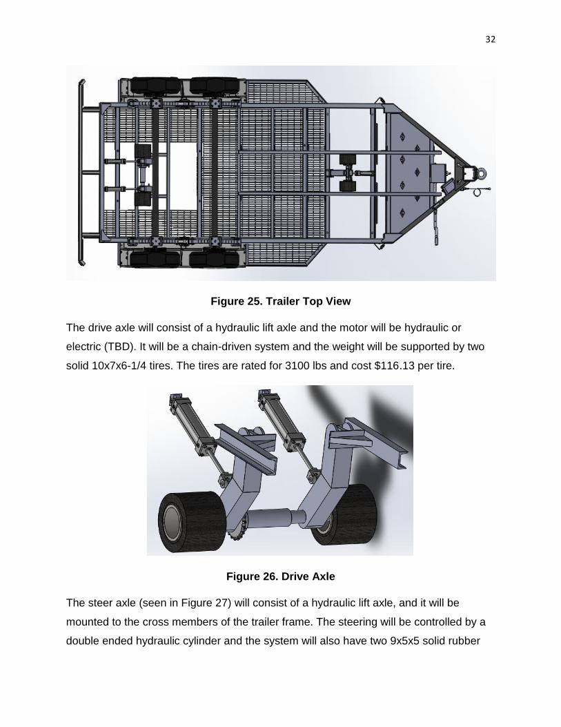
Figure 26. Drive Axle
The steer axle (seen in Figure 27) will consist of a hydraulic lift axle, and it will be
mounted to the cross members of the trailer frame. The steering will be controlled by a
double ended hydraulic cylinder and the system will also have two 9x5x5 solid rubber

33
tires. The tires are rated for 1741 lbs and cost $129.46 per tire. However, the team have
not calculated any real numbers for the steer axle as of yet. The team has to account for
turning forces that could cause the steering axle to shear and break. Upon entering the
spring semester, the team will have performed further calculations to size the steering
arm appropriately and include a factor of safety.
Figure 27. Steer Axle
Figure 28. Steer Axle Mounting
Turning Forces on Steer Arm

34
BAE 1012 Freshman Involvement
For the Charles Machine Works project, the team was assigned two freshman
teams to include in the design.
Team #1 – Tires or Tracks:
1) Determine the pros and cons associated with tires and tracks.
2) Size of tires or tracks needed to carry the load.
3) Cost of tires or tracks.
Team #2 – Remote Control System:
1) Tethered Remote vs. Wireless Remote
2) Control System Parameters
a. Engaged and Disengage dropdown lift axles.
b. Steering and Drive.
Summary
After conducting research over a variety of trailer tugs, it has been noted that
there are advantages and disadvantages with each design. Also, the type of device
used is dependent on the project at hand. As mentioned above, the objective of this
project is the development of a system for Charles Machine that will enable the FX-30
vacuum excavator to move without the use of a standard motorized vehicle. The trailer
the team are designing for is the FX-30 Vacuum Trailer. The final design can be its own
stand-alone system or it can be integrated into the trailer's design. This system should
be designed whereas when not in use, it can be stored and hauled on the vacuum
trailer. Furthermore, by researching trailer caddies such as, the Haulle Tug (seen in
Figure 5) and the MUV 4WD Electric Tug (seen in Figure 6). The team developed a
sense of direction for their own project. Each trailer tug has its own pros and cons such
as: operated via hydraulics, electric motor, multiple tires, wireless or tethered remote,
etc. However, the team should consider which option will be practical and suitable for

35
the client specifications. Some other possible alternatives for moving the trailer that
were researched can be done by using hydraulic rams to move the trailer. The hydraulic
rams would be mounted to the tires of the trailer like what are found on hydraulic
locomotives. Also, the team would incorporate an axle lift to lighten the tongue weight,
which would enable the trailer to be steered more easily. The team also conducted
research over the safety parameters that must be considered throughout the design
along with recommended safety checks for the FX-30 (as specified by Ditch Witch). As
an engineer, one of the fundamental cannons is to ensure the well-being of the public.
Furthermore, the team plans to implement their research over patents, relevant
technology and safety considerations into that of their own design.
Spring Project Schedule
Figure 29. Project Schedule January – February

36
Figure 30. Project Schedule February – End of Semester
Proposed Budget
1) 10 feet of A513 Steel at 20$/ft = $200
2) 3, 2” bore x 8” stroke hydraulic cylinders at $480.75 = $1,442.25
3) 2, 9x5x5 solid rubber tires at $129.46 = $258.92
4) 2, 10x7x6-1/4 solid rubber tires at $116.13 = $232.26
5) Motors = TBD
6) Bolts and Nuts = TBD
Total = $2,133.43

37
Appendix
Patent Searches
i. Compact Multipurpose Trailer
a. At least on battery on said chassis.
b. At least one direct current motor.
c. A control device coupled with said drive train for selectively
controlling rotation of said wheels whereby said tug may be
positioned under said tongue.
d. Battery powered steerable tug apparatus for carrying a cantilevered
tongue of a towable vehicle and comprising.
ii. Tugbot
a. A first wheel drive system assembly adapted to provide the towing
device movement.
b. A second wheel drive system assembly to provide the towing
device movement.
c. Where in said towing device is adapted to provide a non-manned
device for moving said transportation vehicle or other moving
vehicle.
d. A chassis constructed and arranged to support one or more internal
and/or external components of a non-manned towing device for
towing a transportation or other moving vehicle.
iii. Drive Unit for Trailers and Caravans
a. A motorized, maneuverable drive unit having crawler sections with
crawler belts, said drive unit being adapted to be mounted on a
hitch triangle of trailers.
b. The drive unit also comprises an energy supply and mean for
steering and maneuvering the drive unit.
c. The steering and control means comprise a wireless as well as a
non-wireless connection between the motor control system and a
remote control unit.

38
d. A drive unit characterized in that the chassis additionally comprises
an enclosure for a battery, a charging circuit for the battery, an
electrical motor control and an electrical communications circuit for
wireless control of the drive unit.
e. The motor control circuit is provided with a soft start function and is
adapted to control at least two motors individually and to cooperate
with the communications control.
iv. Wheelchair Drive System
a. An axle, defining the axis around which the hub-and-wheel
assembly rotates.
b. A drive wheel assembly, including a drive wheel, an internal gear,
and a tire, said internal gear being supported by a plurality of
circumferentially spaced supporting gears.
c. A driver, supported on said axle and rigidly connected to a hand
ring, forming a driver assembly which is rotatable forward or
rearward by manually rotating said hand ring.
d. A drive engagement gear between said driver and said drive wheel
assembly.
v. Axle Lift
a. It is an object of this invention to provide a device for lifting one axle
of a tractor or trailer free of the road surface when the vehicle is
traveling empty.
b. It is another object of the invention to provide an axle lift having
novel means for engaging an axle to be lifted and the controlled
raising and lowering of the axle.
c. It is another object of the invention to provide means for lifting an
axle on a tractor or trailer and shifting the weight distribution of the
vehicle to provide less tire wear and easier steering of the vehicle.
d. It is another object of the invention to provide an axle lift for lifting
an axle of a tandem trailer to provide less tire wear and greater
traveling stability of the vehicle.

39
Methodology
Drive Wheel Motor Torque Calculations
i. Total tractive effort
a.TTE [lb] = RR [lb] + GR [lb] + FA [lb] (Eq. 1)
TTE = total tractive effort [lb]
RR = force necessary to overcome rolling resistance [lb]
GR = force required to climb a grade [lb]
FA = force required to accelerate to a final velocity [lb]
ii. Rolling Resistance
a. RR [lb] = GVW [lb] x C (Eq. 2)
RR = rolling resistance [lb]
GVW = gross vehicle weight [lb]
C = surface friction
iii. Grade Resistance
a. GR [lb] = GVW [lb] x sin (α)
GR = grade resistance [lb]
GVW = gross vehicle weight [lb]
α = maximum incline angle [degrees]
iv. Acceleration Force
a. FA [lb] = GVW [lb] x Vmax [ft/s] / (32.2 [ft/s2] x ta [s])

40
FA = acceleration force [lb]
GVW = gross vehicle weight [lb]
Vmax = maximum speed [ft/s]
ta = time required to achieve maximum speed [s]
v. Total Tractive Effort
a. TTE [lb] = RR [lb] + GR [lb] + FA [lb]
TTE = sum of forces in: ii+iii+iv
vi. Wheel Motor Torque
a. Tw [lb-in] = TTE [lb] x Rw [in] x RF [-]
Tw = wheel torque [lb-in]
TTE = total tractive effort [lb]
Rw = radius of the wheel/tire [in]
RF = resistance factor [-]
vii. Reality Check
a. MTT = Ww [lb] x µ [-] x Rw
Ww = weight (normal load) on drive wheel [lb]
µ = friction coefficient between the wheel and the ground

41
Rw = radius of the drive wheel/tire [in]

42
References
Code of Ethics. Retrieved from https://www.nspe.org/resources/ethics/code-ethics.
Ditch witch fx-30 specifications. Charles Machine Works Company. Retrieved from
http://www.ditchwitch.com/
Hydraulic trailer tug. Kropf Industrial Inc. Retrieved from
http://www.kropfindustrial.com/conolift/trailer-tugs/haulle-video
Koch, K. Compact multipurpose trailer tug. Google Patents. (2004). Retrieved from
https://www.google.com/patents/US6758291?dq=Compact+Multipurpose+Trailer
+Tug&hl=en&sa=X&ved=0ahUKEwjG2oGrpcfPAhVD6YMKHeIOD7oQ6AEIIDAA
MDML. Drive wheel motor torque calculations. MAE Design and Manufacture
Laboratory. Retrieved from
http://www2.mae.ufl.edu/designlab/motors/EML2322L%20Drive%20Wheel%20M
otor%20Torque%20Calculations.pdf
MUV 4WD electric trailer tug. Nu Star. Retrieved from http://www.nu-
starmhl.com/product/muv-4wd
Payne, F. Steerable and retractable aircraft landing gear. Google Patents. (1956).
Retrieved from
https://www.google.com/patents/US2752112?dq=Steering+and+retractable+aircr
aft+landing+gear&hl=en&sa=X&ved=0ahUKEwijtvydrNrPAhUE_4MKHTy9DcUQ
6AEIODAE
Richnow, E. Axle Llft. Google Patents. (1963). Retrieved from
https://www.google.com/patents/US3096995?dq=axle+lift&hl=en&sa=X&ved=0a
hUKEwi_t4XsrNrPAhUCzoMKHbnUB9EQ6AEILDAC
Schiedegger, J. Tugbot. Google Patents. (2012). Retrieved from
https://www.google.com/patents/US20120215393?dq=Tugbot&hl=en&sa=X&ved
=0ahUKEwiM6eexpMfPAhXG34MKHSsNAgAQ6AEIJTAB
Weaver, M. Wheelchair drive system with ratchet and wheel lock. Google Patents.
(1998). Retrieved from
https://www.google.com/patents/US5743544?dq=wheelchair+drive+system+with

43
+ratchet+and+wheel+lock&hl=en&sa=X&ved=0ahUKEwiF3piuq9rPAhUsxYMKH
Q-sAMAQ6AEIHDAA
Westerdaard, K.E. Drive unit for trailers and caravans. Google Patents. (2009).
Retrieved from
https://www.google.com/patents/US20090308667?dq=Drive+Unit+for+Trailers+a
nd+Caravans&hl=en&sa=X&ved=0ahUKEwispc6VpMfPAhWH7IMKHZl6AQMQ6
AEIJTAB\