Embed Size (px)
Citation preview
City of Winnipeg Water Treatment Program Section 01300 Construction of Water Treatment Plant Building Envelope Page 1 of 4 Bid Opportunity No. 793-2006 March 2007
SUBMITTALS
1. SHOP DRAWINGS
1.1 General
.1 Arrange for the preparation of clearly identified Shop Drawings as specified or as the Contract Administrator may reasonably request. Shop Drawings are to clearly indicate materials, methods of construction, and attachment or anchorage, erection diagrams, connections, explanatory notes, and other information necessary for completion of the Work. Where articles or equipment attach or connect to other articles or equipment, clearly indicate that all such attachments and connections have been properly coordinated, regardless of the trade under which the adjacent articles or equipment will be supplied and installed. Shop Drawings are to indicate their relationship to design Drawings and Specifications. Notify the Contract Administrator of any deviations in Shop Drawings from the requirements of the Contract Documents to allow the Contract Administrator to assess the deviations.
.2 Where all or part of the Shop Drawings are to be prepared under the stamp and seal of a Professional Engineer registered in the Province of Manitoba, the Contract Administrator will limit that review to an assessment of the completeness of the part of the submission so stamped and sealed.
1.2 Submission Requirements
.1 Coordinate each submission with requirements of the Work and Contract Documents. Individual submissions will not be reviewed until all related information is available.
.2 Accompany all submissions with a transmittal letter, in duplicate, containing:
.1 Date
.2 Project title and Bid Opportunity number
.3 Contractor's name and address
.4 Specification Section number for each submittal
.5 Submittal number and revision number in the following format:
.1 793 - Spec Section # - Submittal # - Revision # (e.g. 793-05500-001-1).
.2 The first submittal is numbered 1 with sequential numbering after that for revisions.
.6 Identification and quantity of each Shop Drawing product
.7 Equipment tag number
.8 Other pertinent data
.3 Submissions shall include:
City of Winnipeg Water Treatment Program Section 01300 Construction of Water Treatment Plant Building Envelope Page 2 of 4 Bid Opportunity No. 793-2006 March 2007
SUBMITTALS
.1 Date and revision dates
.2 Project title and number
.3 Name, email address, and address of:
.1 Contractor
.2 Manufacturer
.4 Contractor's stamp, signed by Contractor's authorized representative, certifying approval of submissions, verification of field measurements and compliance with Contract Documents.
.5 As required in the specifications, the seal and signature of a Professional Engineer registered in the Province of Manitoba.
.4 Details of appropriate portions of work as applicable:
.1 Fabrication
.2 Layout showing dimensions including identified field dimensions and clearances
.3 Setting or erection details
.4 Capacities
.5 Performance characteristics
.6 Standards
1.3 Drawings
.1 Original Drawings or modified standard Drawings provided by the Contractor to illustrate details of portions of Work which are specific to project requirements.
.2 Maximum sheet size: 850 x 1050 mm.
.3 Submit twelve (12) prints and one (1) reproducible copy of Shop Drawings. The Contract Administrator will return the reproducible copy with comments transcribed.
.4 Cross-reference Shop Drawing information to applicable portions of the Contract Documents.
.5 Include reviewed Shop Drawings in all O&M Manuals.
City of Winnipeg Water Treatment Program Section 01300 Construction of Water Treatment Plant Building Envelope Page 3 of 4 Bid Opportunity No. 793-2006 March 2007
SUBMITTALS
1.4 Product Data
.1 Product Data; Manufacturer’s catalogue sheets, brochures, literature, performance charts, and diagrams used to illustrate standard manufactured products.
.2 Submit twelve (12) copies of product data.
.3 Sheet size: 215 x 280 mm.
1.5 Procedure and Routing
.1 The Contractor shall provide to the Contract Administrator thirteen (13) printed copies of the Shop Drawings and corresponding submittal transmittal form(s) complete with the information specified in 1.3 Submission Requirements.
.2 The Contractor shall simultaneously email the .pdf version of these same Shop Drawings and submittal transmittal forms to the Contract Administrator. The Contractor shall ensure the .pdf version of the Shop Drawings and corresponding submittal transmittal form(s) are identical to the printed copies being distributed for review. When the total size of the email is greater than 5 MB, the Contractor shall post the .pdf version of the Shop Drawings and submittal transmittal form(s) to an accessible place on the internet (provided by the Contract Administrator) and an e-mail notification is to be sent to all parties listed above when posting is complete.
.3 The routing and the names of individuals responsible for receiving submittals will be identified by the Contract Administrator at the pre-construction meeting held pursuant to D4.2.
.4 Upon review of the Shop Drawings, the Contract Administrator will e-mail the .pdf version of the annotated Shop Drawings and corresponding transmittal form(s) to the Contractor. When the total size of the email is greater than 5 MB, the Contract Administrator will post the .pdf version of the Shop Drawings and corresponding transmittal form(s) to the same accessible place on the internet and an e-mail notification will be sent to the Contractor. Two (2) printed copies of the reviewed Shop Drawings will be sent back to the Contractor.
1.6 Shop Drawing Review
.1 Shop Drawing review by the Contract Administrator is solely to ascertain conformance with the general design concept. Responsibility for the approval of detail design inherent in Shop Drawings rests with the Contractor and review by the Contract Administrator shall not imply such approval.
.2 Review by the Contract Administrator shall not relieve the Contractor of his responsibility for errors or omissions in Shop Drawings or for proper completion of the Work in accordance with the Contract Documents.
.3 Shop Drawings will be returned to the Contractor with one of the following notations:
City of Winnipeg Water Treatment Program Section 01300 Construction of Water Treatment Plant Building Envelope Page 4 of 4 Bid Opportunity No. 793-2006 March 2007
SUBMITTALS
.1 When stamped "REVIEWED", distribute additional copies as required for execution of the Work.
.2 When stamped "REVIEWED AS MODIFIED", ensure that all copies for use are modified and distributed, same as specified for "REVIEWED".
.3 When stamped "REVISE AND RE-SUBMIT", make the necessary revisions, as indicated, consistent with the Contract Documents and submit again for review.
.4 When stamped "NOT REVIEWED", submit other drawings, brochures, etc., for review consistent with the Contract Documents.
.5 Only Shop Drawings bearing "REVIEWED" or "REVIEWED AS MODIFIED" shall be used on the Work unless otherwise authorized by the Contract Administrator.
.4 After submittals are stamped "REVIEWED" or "REVIEWED AS MODIFIED", no further revisions are permitted unless re-submitted to the Contract Administrator for further review.
.5 Any adjustments made on Shop Drawings by the Contract Administrator are not intended to change the Contract Price. If it is deemed that such adjustments affect the Contract Price, clearly state as such in writing prior to proceeding with fabrication and installation of Work.
.6 Make changes in Shop Drawings which the Contract Administrator may require consistent with Contract Documents. When re-submitting, notify the Contract Administrator in writing of any revisions other than those requested by the Contract Administrator.
.7 Shop Drawings indicating design requirements not included in the Contract Documents require the seal of a Professional Engineer registered in the Province of Manitoba. If requested, submit engineering calculations for review, sealed by a Professional Engineer.
1.7 Operating and Maintenance Manuals
.1 Refer to Section 01730 – Operations and Maintenance Manuals.
END OF SECTION
City of Winnipeg Water Treatment Program Section 01450 Construction of Water Treatment Plant Building Envelope Page 1 of 5 Bid Opportunity No. 793-2006 March 2007
QUALITY CONTROL
1. GENERAL
1.1 Section Includes
.1 Quality Control requirements
.2 Inspection and testing, administrative and enforcement requirements.
.3 Tests and mix designs.
.4 Mock-ups.
.5 Mill tests.
1.2 Precedence
.1 Refer to GC:2.
1.3 Related Sections (Not Used)
1.4 References
.1 Unless the edition number and/or date are specified, any reference to the Manufacturer’s and published codes, standards and specifications shall mean the latest edition published by the issuing authority, and in effect three (3) Business Days before the Submission Deadline.
.2 Referenced standards and specifications define minimum requirements. Work in quality exceeding these minimum requirements conforms to the Contract.
.3 Any reference to a Manufacturer’s direction, instruction, or specification shall be deemed to include full information on storing, handling, preparing, mixing, installing, erecting, applying, or other matters concerning the products pertinent to their use and their relationship to the products with which they are incorporated.
.4 Any reference to regulatory authorities includes all authorities having jurisdiction.
.5 Any reference to a Specification section includes all Drawings and Schedules related to the work of that section.
1.5 Inspection
.1 Refer to GC:11.
1.6 Independent Inspection Agencies
.1 Except where inspecting, testing and similar quality control services are specifically indicated to be the Contractor’s responsibility, the City will engage Independent
City of Winnipeg Water Treatment Program Section 01450 Construction of Water Treatment Plant Building Envelope Page 2 of 5 Bid Opportunity No. 793-2006 March 2007
QUALITY CONTROL
Inspection/Testing Agencies for the purpose of inspecting and/or testing portions of Work. Cost of such services will be borne by the City.
.2 Where inspecting, testing and similar quality control services are specifically indicated in the Specification Sections as the Contractor’s responsibility, the Contractor shall engage appropriate Independent Inspection/Testing Agencies. Cost of such services will be borne by the Contractor.
.3 Where the City has engaged an Inspection/Testing Agency for testing and inspection of a part of the Work and the Contractor is also required to engage an Inspection/Testing Agency for the same or related part of the Work; the Contractor shall not employ the same agency engaged by the City without the prior written approval of the Contract Administrator.
.4 Employment of Inspection/Testing Agencies does not relax responsibility to perform Work in accordance with Contract Documents.
.5 If defects are revealed during inspection and/or testing, appointed agency may require additional inspection and/or testing to ascertain full degree of defect. Regardless of original responsibility, pay costs for additional inspection and testing, retesting, re-inspection.
1.7 Access to Work
.1 Refer to GC:11.
1.8 Procedures
.1 Refer to GC:11.
.2 Submit for the Contract Administrator’s approval a written Quality Control Plan prior to start of any on site activities. The plan shall include as a minimum:
.1 Contractor’s approach and philosophy to QA/QC during construction.
.2 Contractor’s method for identification and tracking of all control documents.
.3 Organization chart showing proposed personnel and key contacts for QA/QC.
.4 QC Representative and any subordinate experts. Submit resumes for the Contract Administrator’s approval.
.5 QC Representative’s on Site presence and participation in pre-installation, and Subcontractor meetings.
.6 Contractor’s bi-weekly QC report, including results of contractor certifications, test results, corrective action and follow-up on any deficiencies in the Project’s quality control.
.7 A list of proposed Inspection/Testing Agencies and their qualifications.

City of Winnipeg Water Treatment Program Section 01450 Construction of Water Treatment Plant Building Envelope Page 3 of 5 Bid Opportunity No. 793-2006 March 2007
QUALITY CONTROL
.3 The QC Representative shall be:
.1 Independent of the Contractor’s Supervisor
.2 Qualified by experience and training to monitor construction quality.
.3 Responsible for the overall quality assurance of the Contractor’s work and compliance with Contract.
.4 Responsible to observe and certify the performance of contractor tests and pre-inspections identified, and to attend meetings on site. The QC Representative may elect to use an alternate expert to observe/certify performance.
.5 Authorized to stop work at any time that quality problems necessitate. This authority shall be delineated in a letter of appointment from a Contractor, and shall be included in the QA Plan.
.4 Notify appropriate agency and the Contract Administrator not less than forty eight (48) hours in advance of requirement for tests, in order that attendance arrangements can be made.
.5 Submit samples and/or materials required for testing, as specified in Specification section. Submit with reasonable promptness and in an orderly sequence so as not to cause delay in Work.
.6 Provide labour and facilities to obtain and handle samples and materials on the Site.
.7 Provide suitable facilities for the storage of specimens or samples at correct temperature, free from vibration or damage in accordance with the instruction of the Inspection/Testing Agency and the governing standard.
1.9 Rejected Work
.1 Refer to GC:11.
.2 Make good other Contractor's work damaged by such removals or replacements promptly.
1.10 Reports
.1 For inspecting, testing and similar quality control services which are the Contractor’s responsibility, submit four (4) copies of inspection and test reports to the Contract Administrator, unless specified otherwise.
.2 Each report shall include:
.1 Date of issue
.2 Contract name and number
City of Winnipeg Water Treatment Program Section 01450 Construction of Water Treatment Plant Building Envelope Page 4 of 5 Bid Opportunity No. 793-2006 March 2007
QUALITY CONTROL
.3 Name, address and telephone number of Inspection/Testing Agency
.4 Name and signature of inspector and tester
.5 Date of inspection or test
.6 Identification of the product and Specification section covering inspected or tested Work
.7 Location of the inspection or the location from which the tested product was derived
.8 Type of inspection or test
.9 Complete inspection or test data.
.10 Test results and an interpretation of test results.
.11 Ambient conditions at the time of sample taking and testing.
.12 The remarks and observations on compliance with the Contract Documents
.13 Recommendations on retesting or other corrective action where necessary
.14 Signature of a qualified and authorized representative of the Agency
.3 Submit reports within forty eight (48) hours, and notify the Contract Administrator forthwith if the report indicates improper conditions or procedures.
.4 Refer to Specification section for definitive requirements.
1.11 Tests and Mix Designs
.1 Furnish test results and mix designs as specified or reasonably required by the Contract Administrator.
.2 Refer to Specification section for definitive requirements.
1.12 Mock-ups
.1 Prepare mock-ups as identified in Specification sections. Include for Work of all Sections required to provide mock-ups.
.2 Construct in locations as identified in Specification sections or as otherwise approved by the Contract Administrator.
.3 Prepare mock-ups for the Contract Administrator’s review with reasonable promptness and in an orderly sequence, so as not to cause any delay in Work.
City of Winnipeg Water Treatment Program Section 01450 Construction of Water Treatment Plant Building Envelope Page 5 of 5 Bid Opportunity No. 793-2006 March 2007
QUALITY CONTROL
.4 Failure to prepare mock-ups in ample time is not considered sufficient reason for an extension of Contract Time and no claim for extension by reason of such default will be allowed.
.5 Specification section identifies whether mock-up may remain as part of Work or if it is to be removed and when.
1.13 Mill Tests
.1 Submit mill test certificates as specified or reasonably required by the Contract Administrator.
.2 Refer to Specification section for definitive requirements.
1.14 Equipment and Systems
.1 Submit adjustment and balancing reports for mechanical, electrical, and other equipment systems.
.2 Refer to Specification section for definitive requirements.
END OF SECTION
City of Winnipeg Water Treatment Program Section 01600 Construction of Water Treatment Plant Building Envelope Page 1 of 2 Bid Opportunity No. 793-2006 March 2007
MATERIAL AND EQUIPMENT
1. PRODUCTS
1.1 Manufacturers' Directions
.1 Unless otherwise specified, install or erect all products in accordance with Manufacturers' recommendations. Do not rely on labels or enclosures provided with products. Obtain instructions directly from manufacturers.
.2 Notify the Contract Administrator, in writing, of any conflicts between the Specifications and Manufacturers' instructions so that the Contract Administrator may establish the course of action.
.3 Improper installation or erection of products due to failure in complying with these requirements authorizes the Contract Administrator to require any removal and re-installation that may be considered necessary, at no increase in Contract Price.
2. WORKMANSHIP
2.1 Concealment
.1 In finished areas conceal all pipes, ducts and wiring except where indicated otherwise on Drawings or in Specifications.
.2 Before installation inform the Contract Administrator if there is a contradictory situation.
2.2 Location of Fixtures
.1 Consider the location of fixtures, outlets, and other mechanical and electrical items indicated on Drawings as approximate. The actual location of these items is to be as required or directed to site conditions at the time of installation and as is reasonable.
.2 Before installation inform the Contract Administrator if there is a contradictory situation. Install as directed.
2.3 Cutting and Remedial Work
.1 Perform all cutting and remedial work that may be required to make the several parts of the Work come together properly. Coordinate and schedule the Work to ensure that cutting and remedial work are kept to a minimum.
.2 Employ specialists familiar with the materials affected in performing cutting and remedial work. Perform in a manner to neither damage nor endanger any portion of the Work.
.3 Do not cut, drill or sleeve any load-bearing members without written acceptance of the Contract Administrator.
City of Winnipeg Water Treatment Program Section 01600 Construction of Water Treatment Plant Building Envelope Page 2 of 2 Bid Opportunity No. 793-2006 March 2007
MATERIAL AND EQUIPMENT
.4 The Contractor is to perform work so as to minimize dust.
2.4 Fastenings
.1 Provide metal fastenings and accessories in same texture, colour and finish as adjacent material unless otherwise specified.
.2 Prevent electrolytic action between dissimilar metals and materials.
.3 Use non-corrosive, non-staining fasteners and anchors for securing exterior Work unless otherwise specified.
.4 Space anchors within their load limit or shear capacity and ensure that they provide positive permanent anchorage. Wood plugs are not acceptable.
.5 Keep exposed fastenings to a minimum, space evenly and lay out neatly.
.6 Fastenings which cause spalling or cracking of material to which anchorage is made are not acceptable.
3. MEASUREMENT
3.1 Metric Project
.1 Unless otherwise noted, this Project has been designed and is to be constructed in the SI nominal metric system of measurements.
END OF SECTION
City of Winnipeg Water Treatment Program Section 01730 Construction of Water Treatment Plant Building Envelope Page 1 of 2 Bid Opportunity No. 793-2006 March 2007
OPERATION AND MAINTENANCE MANUALS
1. DESCRIPTION
.1 This Section supplements the requirements for the provision of O&M Manuals as described in Section 01300 – Submittals.
.2 Furnish complete operations manuals and maintenance information as specified in this Section for installation, check-out, operation, maintenance, and lubrication requirements for each system.
.3 Customize the operations manuals and maintenance information to describe the systems actually furnished. Do not include extraneous data, options, or sizes not furnished (cross out or remove if required).
.4 Assemble, coordinate, bind, and index required data into an O&M Manual.
.5 Three (3) draft copies of the manuals shall be submitted a minimum of sixty (60) days prior to Substantial Performance of the Work for review and comments. A maximum of eight (8) weeks after review, twelve (12) copies of the final manuals shall be supplied.
.6 In addition to the twelve (12) hard copies, submit an electronic version of the O&M Manual.
.7 Materials: Label each Section with tabs protected with celluloid covers, fastened to hard paper dividing sheets.
.8 Type lists and notes.
.9 Drawings, diagrams and Manufacturer's literature must be legible. Drawings larger than 280 x 430 mm must be folded and placed inside plastic pockets.
2. OPERATION AND MAINTENANCE MANUAL CONTENTS AND ORGANIZATION
.1 Provide the Manufacturer’s standard O&M manuals for the systems supplied. If the Manufacturer's standard manuals do not contain all the required information, provide the missing information in supplementary documents and Drawings inserted behind appropriate tabs in the manual binder.
.2 When more than one (1) piece of identical system is supplied, provide only one (1) set of operations manuals.
.3 One (1) set of operations manuals may be provided when more than one (1) piece of similar equipment or instruments are supplied, such as different sizes of the same model, and all similar pieces are covered in the same standard Manufacturer's O&M manual.
.4 When similar equipment or instruments are provided by the same Manufacturer, but are not covered in the same standard Manufacturer's O&M manual, their specific manuals may be bound in the same 3-ring binder. Separate specific manuals with tab dividers labelled with the appropriate equipment numbers.
City of Winnipeg Water Treatment Program Section 01730 Construction of Water Treatment Plant Building Envelope Page 2 of 2 Bid Opportunity No. 793-2006 March 2007
OPERATION AND MAINTENANCE MANUALS
.5 Provide a cover sheet, bound as the first page of each manual, with the following information:
.1 Contract name and number.
.2 System identification.
.6 Provide a table of contents listing the contents of the manual and identifying where specific information can be located.
3. FIELD CHANGES NOT APPLICABLE
.1 Following the acceptable installation and operation of an equipment item, modify and supplement the item's instructions and procedures to reflect any field changes or information requiring field data.
4. COMMISSIONING DATA
.1 Provide in hard cover 3-ring binders for 215 x 280 mm paper labelled "COMMISSIONING DATA" one (1) copy of:
.1 All completed equipment testing and commissioning forms.
.2 All completed equipment checklists and performance reports, including noise and vibration analysis, instrumentation calibration data, and all other relevant information.
.3 All system performance reports.
5. WARRANTIES
.1 Provide in hard cover 3-ring binders for 215 x 280 mm paper labelled "WARRANTIES" one (1) copy of:
.1 Manufacturers' standard Warrants and Guarantees. Include the name and telephone number of the contact person. Indicate the time frame of each Warrant or Guarantee on the list.
END OF SECTION
City of Winnipeg Water Treatment Program Section 03200 Construction of Water Treatment Plant Building Envelope Page 1 of 3 Bid Opportunity No. 793-2006 March 2007
CONCRETE REINFORCEMENT
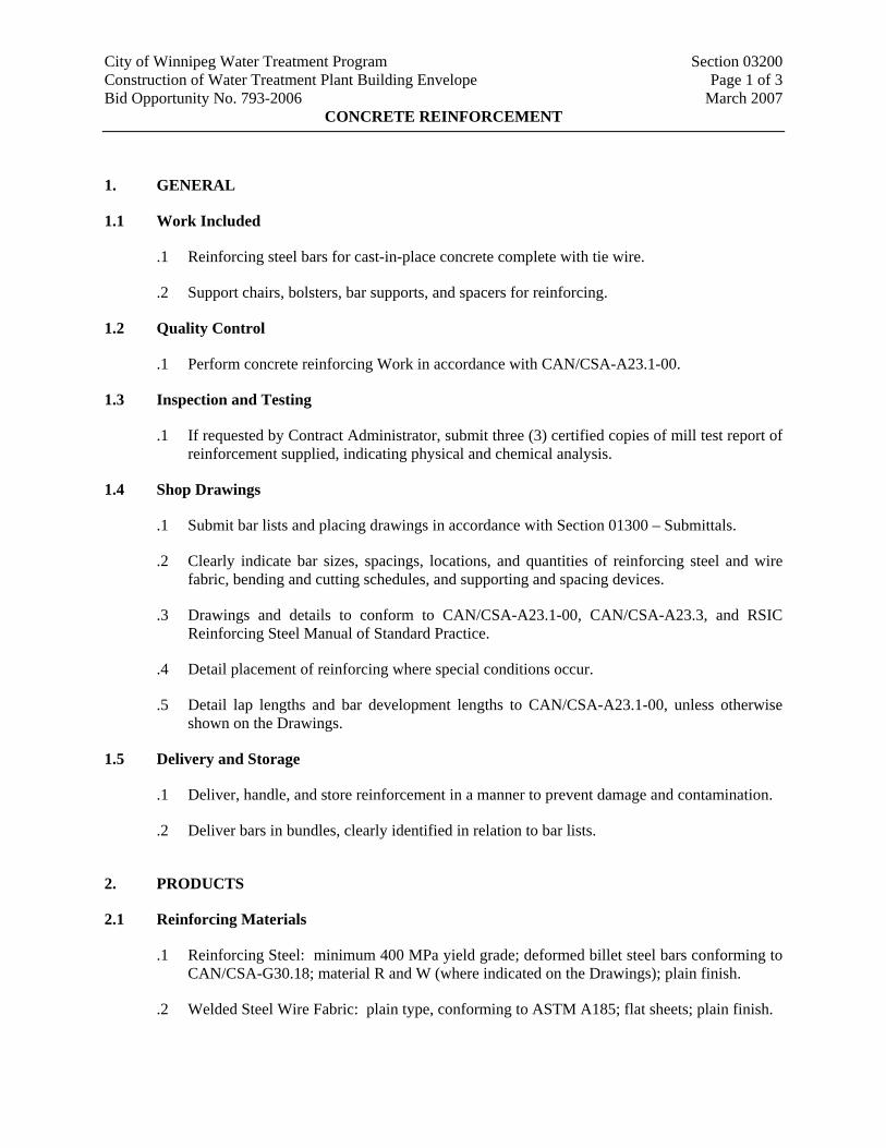
1. GENERAL
1.1 Work Included
.1 Reinforcing steel bars for cast-in-place concrete complete with tie wire.
.2 Support chairs, bolsters, bar supports, and spacers for reinforcing.
1.2 Quality Control
.1 Perform concrete reinforcing Work in accordance with CAN/CSA-A23.1-00.
1.3 Inspection and Testing
.1 If requested by Contract Administrator, submit three (3) certified copies of mill test report of reinforcement supplied, indicating physical and chemical analysis.
1.4 Shop Drawings
.1 Submit bar lists and placing drawings in accordance with Section 01300 – Submittals.
.2 Clearly indicate bar sizes, spacings, locations, and quantities of reinforcing steel and wire fabric, bending and cutting schedules, and supporting and spacing devices.
.3 Drawings and details to conform to CAN/CSA-A23.1-00, CAN/CSA-A23.3, and RSIC Reinforcing Steel Manual of Standard Practice.
.4 Detail placement of reinforcing where special conditions occur.
.5 Detail lap lengths and bar development lengths to CAN/CSA-A23.1-00, unless otherwise shown on the Drawings.
1.5 Delivery and Storage
.1 Deliver, handle, and store reinforcement in a manner to prevent damage and contamination.
.2 Deliver bars in bundles, clearly identified in relation to bar lists.
2. PRODUCTS
2.1 Reinforcing Materials
.1 Reinforcing Steel: minimum 400 MPa yield grade; deformed billet steel bars conforming to CAN/CSA-G30.18; material R and W (where indicated on the Drawings); plain finish.
.2 Welded Steel Wire Fabric: plain type, conforming to ASTM A185; flat sheets; plain finish.
City of Winnipeg Water Treatment Program Section 03200 Construction of Water Treatment Plant Building Envelope Page 2 of 3 Bid Opportunity No. 793-2006 March 2007
CONCRETE REINFORCEMENT
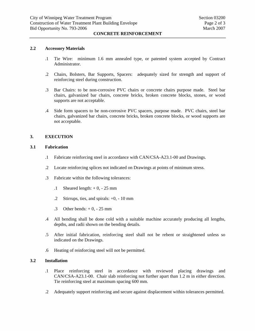
2.2 Accessory Materials
.1 Tie Wire: minimum 1.6 mm annealed type, or patented system accepted by Contract Administrator.
.2 Chairs, Bolsters, Bar Supports, Spacers: adequately sized for strength and support of reinforcing steel during construction.
.3 Bar Chairs: to be non-corrosive PVC chairs or concrete chairs purpose made. Steel bar chairs, galvanized bar chairs, concrete bricks, broken concrete blocks, stones, or wood supports are not acceptable.
.4 Side form spacers to be non-corrosive PVC spacers, purpose made. PVC chairs, steel bar chairs, galvanized bar chairs, concrete bricks, broken concrete blocks, or wood supports are not acceptable.
3. EXECUTION
3.1 Fabrication
.1 Fabricate reinforcing steel in accordance with CAN/CSA-A23.1-00 and Drawings.
.2 Locate reinforcing splices not indicated on Drawings at points of minimum stress.
.3 Fabricate within the following tolerances:
.1 Sheared length: + 0, - 25 mm
.2 Stirrups, ties, and spirals: +0, - 10 mm
.3 Other bends: + 0, - 25 mm
.4 All bending shall be done cold with a suitable machine accurately producing all lengths, depths, and radii shown on the bending details.
.5 After initial fabrication, reinforcing steel shall not be rebent or straightened unless so indicated on the Drawings.
.6 Heating of reinforcing steel will not be permitted.
3.2 Installation
.1 Place reinforcing steel in accordance with reviewed placing drawings and CAN/CSA-A23.1-00. Chair slab reinforcing not further apart than 1.2 m in either direction. Tie reinforcing steel at maximum spacing 600 mm.
.2 Adequately support reinforcing and secure against displacement within tolerances permitted.

City of Winnipeg Water Treatment Program Section 03200 Construction of Water Treatment Plant Building Envelope Page 3 of 3 Bid Opportunity No. 793-2006 March 2007
CONCRETE REINFORCEMENT
.3 Place reinforcing steel to provide concrete cover required by CAN/CSA-A23.1-00, but not less than shown below or noted otherwise on the Drawings:
.1 Beam stirrups: 40 mm unless noted otherwise; main steel: 50 mm.
.2 Slabs (top and bottom): 50 mm.
.3 Column ties: 40 mm; main steel: 50 mm.
.4 Walls: 50 mm unless noted otherwise.
.5 Concrete formed against earth (including bottom of slab on grade): 75 mm.
.4 Maintain alignment as follows:
.1 Slabs: ±5 mm.
.2 Other structural members: ±10 mm.
.3 Rebar bends and ends: ±50 mm.
.5 Do not disturb or damage polyethylene film or void form while placing reinforcing steel.
.6 Install purpose made highly visible protective safety caps on all exposed projecting bar ends.
3.3 Cleaning
.1 Ensure concrete reinforcing is clean and free from oil and deleterious matter.
.2 Remove all loose scale, loose rust, concrete from prior pours, and other deleterious matter from surfaces of reinforcing.
.3 Remove concrete splatter on bars before concrete has hardened.
END OF SECTION

City of Winnipeg Water Treatment Program Section 03300 Construction of Water Treatment Plant Building Envelope Page 1 of 12 Bid Opportunity No. 793-2006 March 2007
CAST-IN-PLACE CONCRETE
1. GENERAL
1.1 Work Included
.1 All reinforced cast-in-place concrete Masonry infill.
.2 Setting anchors, inserts, frames, sleeves, and other items supplied by other Sections.
.3 Repairing concrete imperfections.
.4 Concrete curing.
1.2 Quality Control
.1 Cast-in-place concrete shall conform to the CAN/CSA-A23.1-00.
.2 Testing shall conform to CAN/CSA-A23.2-00.
.3 These standards shall be available in the Contractor’s Site office for reference by the Contractor, sub-trades, and Contract Administrator.
.4 A Concrete Review Report will be completed with each concrete pour. Each Concrete Review Report shall be signed by the Contractor and submitted to the Contract Administrator.
1.3 Qualification
.1 Concrete flatwork finishing is to be done by an established firm having at least five years of proven, satisfactory experience in this trade and employing skilled personnel.
.2 Submit proof of qualifications in writing to the Contract Administrator.
1.4 Inspection and Testing
.1 Notify the Contract Administrator at least forty eight (48) hours before complete formwork and concrete reinforcement is ready for review. Reinforcing in walls shall be reviewed prior to closing forms.
.2 Allow ample time for notification, review, and corrective Work, if required, before scheduling concrete placement.
.3 Concrete sampling, inspection, and testing is to be performed by a CSA certified inspection and testing firm appointed and paid for by the City.
.4 Provide unencumbered access to all portions of Work and cooperate with appointed firm.
.5 Submit proposed mix design statements of each class of concrete to the Contract Administrator for review four weeks prior to commencement of the Work. If blended cement is proposed for sulphate resistant concrete, testing data supporting conformance to
City of Winnipeg Water Treatment Program Section 03300 Construction of Water Treatment Plant Building Envelope Page 2 of 12 Bid Opportunity No. 793-2006 March 2007
CAST-IN-PLACE CONCRETE
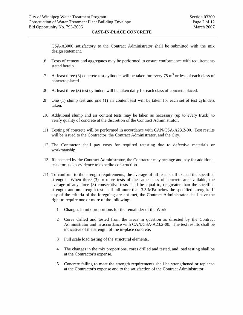
CSA-A3000 satisfactory to the Contract Administrator shall be submitted with the mix design statement.
.6 Tests of cement and aggregates may be performed to ensure conformance with requirements stated herein.
.7 At least three (3) concrete test cylinders will be taken for every 75 m3 or less of each class of concrete placed.
.8 At least three (3) test cylinders will be taken daily for each class of concrete placed.
.9 One (1) slump test and one (1) air content test will be taken for each set of test cylinders taken.
.10 Additional slump and air content tests may be taken as necessary (up to every truck) to verify quality of concrete at the discretion of the Contract Administrator.
.11 Testing of concrete will be performed in accordance with CAN/CSA-A23.2-00. Test results will be issued to the Contractor, the Contract Administrator, and the City.
.12 The Contractor shall pay costs for required retesting due to defective materials or workmanship.
.13 If accepted by the Contract Administrator, the Contractor may arrange and pay for additional tests for use as evidence to expedite construction.
.14 To conform to the strength requirements, the average of all tests shall exceed the specified strength. When three (3) or more tests of the same class of concrete are available, the average of any three (3) consecutive tests shall be equal to, or greater than the specified strength, and no strength test shall fall more than 3.5 MPa below the specified strength. If any of the criteria of the foregoing are not met, the Contract Administrator shall have the right to require one or more of the following:
.1 Changes in mix proportions for the remainder of the Work.
.2 Cores drilled and tested from the areas in question as directed by the Contract Administrator and in accordance with CAN/CSA-A23.2-00. The test results shall be indicative of the strength of the in-place concrete.
.3 Full scale load testing of the structural elements.
.4 The changes in the mix proportions, cores drilled and tested, and load testing shall be at the Contractor's expense.
.5 Concrete failing to meet the strength requirements shall be strengthened or replaced at the Contractor's expense and to the satisfaction of the Contract Administrator.

City of Winnipeg Water Treatment Program Section 03300 Construction of Water Treatment Plant Building Envelope Page 3 of 12 Bid Opportunity No. 793-2006 March 2007
CAST-IN-PLACE CONCRETE
2. PRODUCTS
2.1 Concrete Materials
.1 Cement: Normal Type 10 (Type GU) Portland Cement conforming to CAN/CSA-A3000 and sulphate resistant Type 50 (Type HS) Portland Cement or HSb conforming to CAN/CSA-A3000.
.2 Fine Aggregate: conforming to Normal-Density Fine Aggregate, CAN/CSA-23.1-00. If requested by the Contract Administrator, submit evidence at least two weeks before use in concrete mix showing conformance to Normal-Density Fine Aggregate, CAN/CSA-A23.1-00, Table 4 and Table 6.
.3 Coarse Aggregate: conforming to Normal-Density Coarse Aggregate, CAN/CSA-23.1-00, Group I, 20 to 5 mm, and 10 to 2.5 mm. If requested by the Contract Administrator, submit evidence at least two (2) weeks before use in concrete mix showing conformance to Normal-Density Coarse Aggregate, CAN/CSA-A23.1-00, Table 5 and Table 6. Group II may be used for special requirements such as gap grading, pumping, or for blending two (2) or more sizes to produce Group I gradings.
.4 Ensure that no aggregates are used that may undergo volume change due to alkali reactivity, moisture retention, or other causes. Confirm suitability of aggregate with a petrographic analysis report if requested by the Contract Administrator.
.5 Water: potable, clean, and free from injurious amounts of oil, alkali, organic matter, or other deleterious matter.
.6 Materials are to be obtained from the same source of supply or Manufacturer for the duration of the Work.
.7 Supplementary cementing materials: conforming to CAN/CSA-A3000.
2.2 Admixtures
.1 No admixtures other than air-entraining agent, water-reducing agent, and superplasticizer shall be used without the written authorization of the Contract Administrator, unless specified.
.2 Air entrainment: conforming to ASTM Standard C260.
.3 Water-reducing agent: Type WN conforming to ASTM Standard C494.
.4 Superplacticizer: conforming to ASTM Standard C494.
.5 General Chemical Admixtures: conforming to ASTM Standard C494.
.6 Calcium chloride or admixtures containing calcium chloride shall not be used in concrete.
City of Winnipeg Water Treatment Program Section 03300 Construction of Water Treatment Plant Building Envelope Page 4 of 12 Bid Opportunity No. 793-2006 March 2007
CAST-IN-PLACE CONCRETE
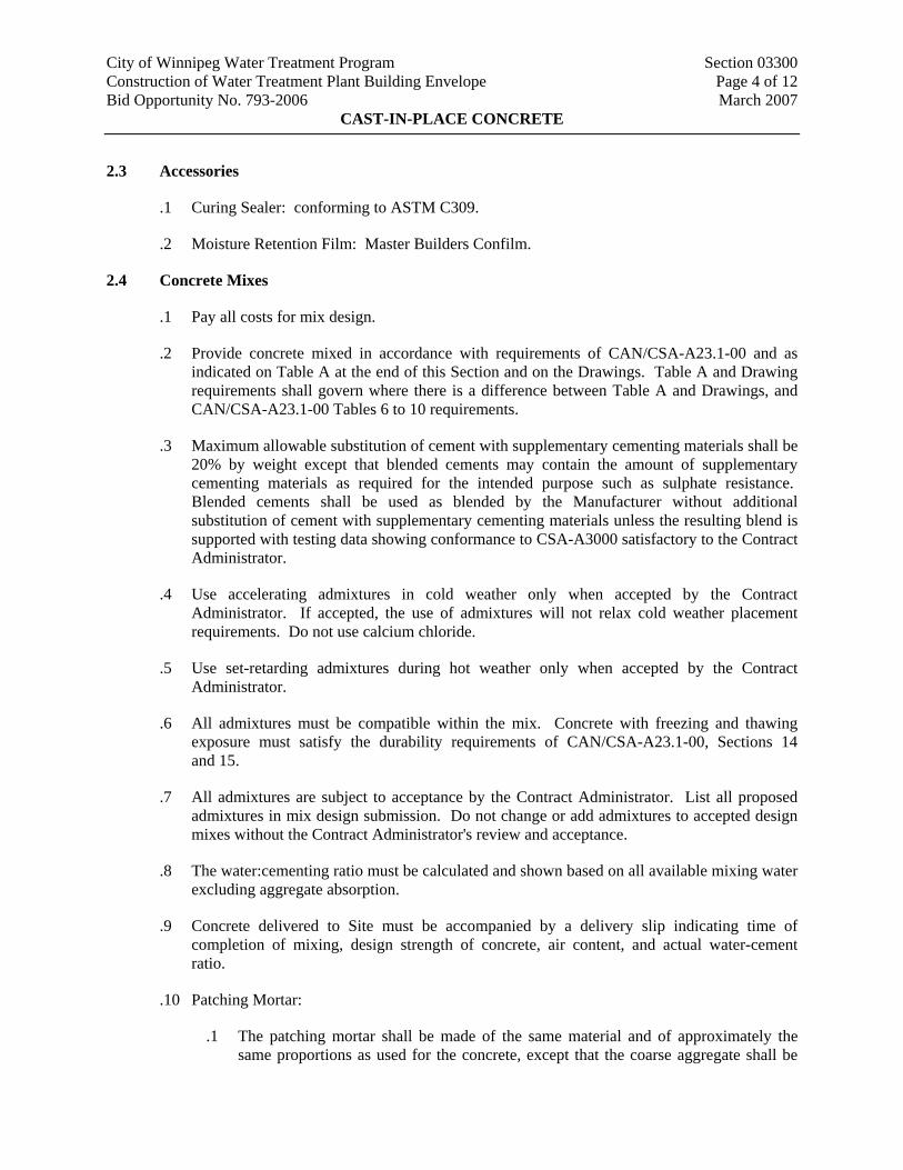
2.3 Accessories
.1 Curing Sealer: conforming to ASTM C309.
.2 Moisture Retention Film: Master Builders Confilm.
2.4 Concrete Mixes
.1 Pay all costs for mix design.
.2 Provide concrete mixed in accordance with requirements of CAN/CSA-A23.1-00 and as indicated on Table A at the end of this Section and on the Drawings. Table A and Drawing requirements shall govern where there is a difference between Table A and Drawings, and CAN/CSA-A23.1-00 Tables 6 to 10 requirements.
.3 Maximum allowable substitution of cement with supplementary cementing materials shall be 20% by weight except that blended cements may contain the amount of supplementary cementing materials as required for the intended purpose such as sulphate resistance. Blended cements shall be used as blended by the Manufacturer without additional substitution of cement with supplementary cementing materials unless the resulting blend is supported with testing data showing conformance to CSA-A3000 satisfactory to the Contract Administrator.
.4 Use accelerating admixtures in cold weather only when accepted by the Contract Administrator. If accepted, the use of admixtures will not relax cold weather placement requirements. Do not use calcium chloride.
.5 Use set-retarding admixtures during hot weather only when accepted by the Contract Administrator.
.6 All admixtures must be compatible within the mix. Concrete with freezing and thawing exposure must satisfy the durability requirements of CAN/CSA-A23.1-00, Sections 14 and 15.
.7 All admixtures are subject to acceptance by the Contract Administrator. List all proposed admixtures in mix design submission. Do not change or add admixtures to accepted design mixes without the Contract Administrator's review and acceptance.
.8 The water:cementing ratio must be calculated and shown based on all available mixing water excluding aggregate absorption.
.9 Concrete delivered to Site must be accompanied by a delivery slip indicating time of completion of mixing, design strength of concrete, air content, and actual water-cement ratio.
.10 Patching Mortar:
.1 The patching mortar shall be made of the same material and of approximately the same proportions as used for the concrete, except that the coarse aggregate shall be

City of Winnipeg Water Treatment Program Section 03300 Construction of Water Treatment Plant Building Envelope Page 5 of 12 Bid Opportunity No. 793-2006 March 2007
CAST-IN-PLACE CONCRETE
omitted and the mortar shall consist of not more than 1 part cement to 2.5 parts sand by damp loose volume.
.2 White Portland cement shall be substituted for a part of the grey Portland cement on exposed concrete in order to produce a colour matching the colour of the surrounding concrete, as determined by trial patches.
.3 The quantity of mixing water shall be no more than necessary for handling or placing. Mixing water shall include 1 part latex bonding agent to 3 parts water. Maximum water to cement ratio shall be 0.40.
.11 Self-compacting concrete mixes will not be permitted for use on this Work.
3. EXECUTION
3.1 Placing Concrete
.1 Place concrete in accordance with requirements of CAN/CSA-A23.1-00 and as indicated on the Drawings. Layout of the Work and accuracy of same is the Contractor's sole responsibility.
.2 Notify the Contract Administrator a minimum of twenty four (24) hours prior to pouring concrete. Under no circumstances shall concrete be poured without notifying Contract Administrator, or in his absence, arranging for review of the Work and sampling of concrete.
.3 The concrete shall be placed rapidly and evenly as near to its final position as possible to reduce the risk of segregation, flowlines, and cold joints. Concrete shall be placed within 1.5 hours of mixing.
.4 Ensure all anchor bolts, seats, plates, and other items to be cast into concrete are securely placed and will not interfere with concrete placement.
.5 All equipment for transporting the concrete shall be cleaned of hardened concrete and foreign materials before placing concrete.
.6 Immediately before concrete is placed, Contractor shall carefully inspect all forms to ensure that they are properly placed, sufficiently rigid and tight, and that all reinforcing steel and embedded parts are in the correct position and secured against movement during the placing operation. All forms shall be thoroughly cleaned..
.7 Concrete shall be handled from the mixer to the place of final deposit as rapidly as practicable by methods that will prevent the separation or loss of the ingredients. Concrete shall be deposited in the forms as nearly as practicable in its final position to avoid re-handling or flowing. Vibrators shall not be used to move concrete. Under no circumstances shall the concrete, which has partially hardened, be deposited in the forms.
.8 Concrete shall be thoroughly compacted by mechanical vibrators during placing operations. Concrete shall be thoroughly worked around the reinforcement, embedded fixtures, and into the corners of the forms.

City of Winnipeg Water Treatment Program Section 03300 Construction of Water Treatment Plant Building Envelope Page 6 of 12 Bid Opportunity No. 793-2006 March 2007
CAST-IN-PLACE CONCRETE
.9 Vibrate concrete using the appropriate size equipment as placing proceeds, in accordance with CAN/CSA-A23.1-00. Check frequency and amplitude of vibrations prior to use. Provide additional standby vibrators in the event of equipment failure.
.10 Prepare set or existing concrete by removing all laitance and loose or unsound materials and apply bonding agent in accordance with Manufacturer’s recommendations.
.11 Where placing operations would involve dropping the concrete more than 1.5 m, it shall be placed through canvas hoses or galvanized iron chutes. Concrete shall not be raised at a rate greater than that for which proper vibration may be affected.
.12 In locations where new concrete is dowelled to existing concrete, drill holes in existing concrete, thoroughly clean the holes, place non-shrink grout in holes, and insert steel dowels so that grout is packed solidly for full depth around the dowels.
.13 A minimum of three (3) Calendar Days shall elapse between adjacent pours separated by construction joints or expansion joints.
.14 Do not place concrete if carbon dioxide producing equipment has been in operation in the building or in the enclosure during the twelve (12) hours preceding the pour. This equipment shall not be used during placing or for twenty four (24) hours after placing. During placing and curing concrete, surfaces shall be protected by formwork or an impermeable membrane from direct exposure to carbon dioxide, combustion gases, or drying from heaters.
.15 Honeycomb or embedded debris is not acceptable.
.16 Remove and replace defective concrete.
.17 Maintain accurate records of cast-in-place concrete items. Record date, location of pour, quantity, air temperature, and test samples taken.
.18 Prior to the erection of the formwork for walls and beams, the construction joint shall be sand blasted and cleaned as per Clause 3.15 – Construction Joints, of this specification section.
.19 At the start of casting of walls or beams on slabs, a layer of grout slurry approximately 12 mm to 25 mm thick shall be placed immediately prior to the placement of concrete.
3.2 Cold Weather Concreting
.1 The requirements of this section shall be applied to all concreting operations during cold weather, i.e., if the mean daily temperature falls below 5°C during placing or curing.
.2 Supplementary equipment as required below shall be at the Site if concrete is likely to be placed in cold weather.
.3 Formwork and reinforcing steel shall be heated to at least 5°C before concrete is placed.
City of Winnipeg Water Treatment Program Section 03300 Construction of Water Treatment Plant Building Envelope Page 7 of 12 Bid Opportunity No. 793-2006 March 2007
CAST-IN-PLACE CONCRETE
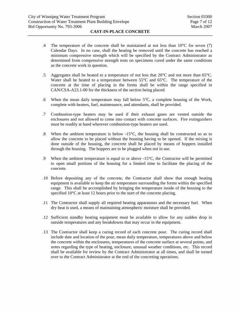
.4 The temperature of the concrete shall be maintained at not less than 10°C for seven (7) Calendar Days. In no case, shall the heating be removed until the concrete has reached a minimum compressive strength which will be specified by the Contract Administrator as determined from compressive strength tests on specimens cured under the same conditions as the concrete work in question.
.5 Aggregates shall be heated to a temperature of not less that 20°C and not more than 65°C. Water shall be heated to a temperature between 55°C and 65°C. The temperature of the concrete at the time of placing in the forms shall be within the range specified in CAN/CSA-A23.1-00 for the thickness of the section being placed.
.6 When the mean daily temperature may fall below 5°C, a complete housing of the Work, complete with heaters, fuel, maintenance, and attendants, shall be provided.
.7 Combustion-type heaters may be used if their exhaust gases are vented outside the enclosures and not allowed to come into contact with concrete surfaces. Fire extinguishers must be readily at hand wherever combustion-type heaters are used.
.8 When the ambient temperature is below -15°C, the housing shall be constructed so as to allow the concrete to be placed without the housing having to be opened. If the mixing is done outside of the housing, the concrete shall be placed by means of hoppers installed through the housing. The hoppers are to be plugged when not in use.
.9 When the ambient temperature is equal to or above -15°C, the Contractor will be permitted to open small portions of the housing for a limited time to facilitate the placing of the concrete.
.10 Before depositing any of the concrete, the Contractor shall show that enough heating equipment is available to keep the air temperature surrounding the forms within the specified range. This shall be accomplished by bringing the temperature inside of the housing to the specified 10°C at least 12 hours prior to the start of the concrete placing.
.11 The Contractor shall supply all required heating apparatuses and the necessary fuel. When dry heat is used, a means of maintaining atmospheric moisture shall be provided.
.12 Sufficient standby heating equipment must be available to allow for any sudden drop in outside temperatures and any breakdowns that may occur in the equipment.
.13 The Contractor shall keep a curing record of each concrete pour. The curing record shall include date and location of the pour, mean daily temperature, temperatures above and below the concrete within the enclosures, temperatures of the concrete surface at several points, and notes regarding the type of heating, enclosure, unusual weather conditions, etc. This record shall be available for review by the Contract Administrator at all times, and shall be turned over to the Contract Administrator at the end of the concreting operations.

City of Winnipeg Water Treatment Program Section 03300 Construction of Water Treatment Plant Building Envelope Page 8 of 12 Bid Opportunity No. 793-2006 March 2007
CAST-IN-PLACE CONCRETE
3.3 Hot Weather Concreting
.1 General
.1 The requirements of this Clause shall be applied during hot weather, i.e., when air temperatures are above 25°C during placing.
.2 Concrete shall be placed at as low a temperature as possible, preferably below 15°C, but not above 27°C. Aggregate stockpiles may be cooled by water sprays and sun shades.
.3 Ice may be substituted for a portion of the mixing water provided the ice has melted by the time mixing is completed.
.4 Forms and conveying equipment shall be kept as cool as possible before concreting by shading them from the sun, painting their surfaces white, and/or the use of water sprays.
.5 Sun shades and wind breaks shall be used as required during placing and finishing.
.6 Work shall be planned so that concrete can be placed as quickly as possible to avoid “cold joints”.
.7 The Contract Administrator’s acceptance is necessary before the Contractor may use admixtures such as retardants to delay setting, or water-reducing agents to maintain workability and strength, and these are to be included in the mix designs submitted to the Contract Administrator.
.8 Curing shall follow immediately after the finishing operation.
.2 Hot-Weather Curing
.1 When the air temperature is at or above 25°C, curing shall be accomplished by water or by using saturated absorptive fabric, in order to achieve cooling by evaporation. Mass concrete shall be water cured for the basic curing period when the air temperature is at or above 20°C, in order to minimize the temperature rise of the concrete.
.3 Job Preparation
.1 When the air temperature is at or above 25°C, or when there is the probability of its rising to 25°C during the placing period, facilities shall be provided for protection of the concrete in place from the effects of hot and/or drying weather conditions. Under severe drying conditions, as defined under “Severe Drying Conditions” below, the formwork, reinforcement, and concreting equipment shall be protected from the direct rays of the sun or cooled by fogging and evaporation.
City of Winnipeg Water Treatment Program Section 03300 Construction of Water Treatment Plant Building Envelope Page 9 of 12 Bid Opportunity No. 793-2006 March 2007
CAST-IN-PLACE CONCRETE
.4 Concrete Temperature
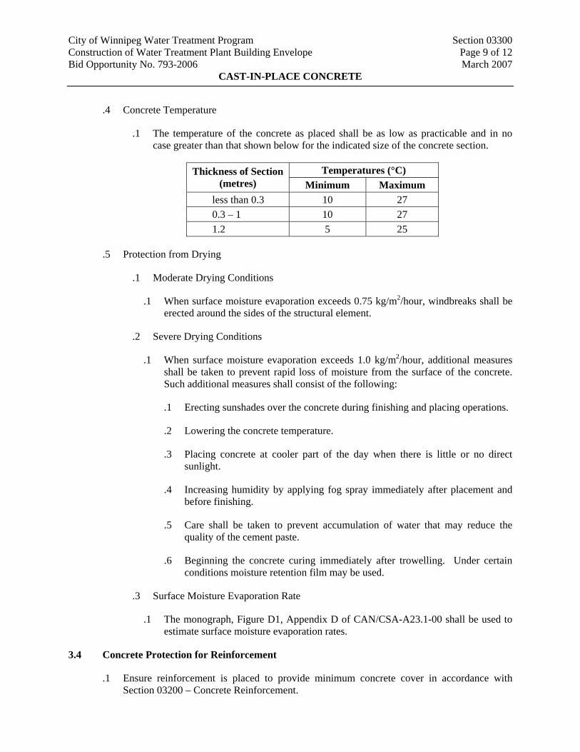
.1 The temperature of the concrete as placed shall be as low as practicable and in no case greater than that shown below for the indicated size of the concrete section.
Temperatures (°C) Thickness of Section (metres) Minimum Maximum
less than 0.3 10 27 0.3 – 1 10 27 1.2 5 25
.5 Protection from Drying
.1 Moderate Drying Conditions
.1 When surface moisture evaporation exceeds 0.75 kg/m2/hour, windbreaks shall be erected around the sides of the structural element.
.2 Severe Drying Conditions
.1 When surface moisture evaporation exceeds 1.0 kg/m2/hour, additional measures shall be taken to prevent rapid loss of moisture from the surface of the concrete. Such additional measures shall consist of the following:
.1 Erecting sunshades over the concrete during finishing and placing operations.
.2 Lowering the concrete temperature.
.3 Placing concrete at cooler part of the day when there is little or no direct sunlight.
.4 Increasing humidity by applying fog spray immediately after placement and before finishing.
.5 Care shall be taken to prevent accumulation of water that may reduce the quality of the cement paste.
.6 Beginning the concrete curing immediately after trowelling. Under certain conditions moisture retention film may be used.
.3 Surface Moisture Evaporation Rate
.1 The monograph, Figure D1, Appendix D of CAN/CSA-A23.1-00 shall be used to estimate surface moisture evaporation rates.
3.4 Concrete Protection for Reinforcement
.1 Ensure reinforcement is placed to provide minimum concrete cover in accordance with Section 03200 – Concrete Reinforcement.
City of Winnipeg Water Treatment Program Section 03300 Construction of Water Treatment Plant Building Envelope Page 10 of 12 Bid Opportunity No. 793-2006 March 2007
CAST-IN-PLACE CONCRETE
3.5 Construction Tolerance
.1 The Work shall be carefully and accurately set out; true to the positioning, levels, slopes, and dimensions shown on the Drawings and conforming to Section 03200 – Concrete Reinforcement.
.1 Sizes of Member or Thickness of Slabs: + 6 mm, - 0 mm.
.2 Cover of Concrete over Reinforcement: ± 3 mm.
.3 Variations from Plumb: 6 mm in 3 m, 10 mm maximum.
.4 Variations from Flat: 3 mm in 3 m, 6 mm maximum.
.2 If these tolerances are exceeded, the Contractor may, at the discretion of the Contract Administrator, be required to remove and replace or to modify the placed concrete before acceptance. The costs incurred by the Contract Administrator for such investigation, testing, or review of reconstruction and the cost of reconstruction shall be borne by the Contractor.
3.6 Curing and Protection
.1 Cure and protect freshly placed concrete in accordance with Clause 21 of CAN/CSA-A23.1-00.
.2 All concrete shall receive moist curing for a period of at least seven (7) Calendar Days. One of the following methods shall be used as soon as the concrete has hardened sufficiently to prevent marring:
.1 Surface covered with canvas or other satisfactory material and kept thoroughly and continuously wet with soaker hoses.
.2 A liquid membrane forming curing sealer, applied at the rate recommended by the Manufacturer. Curing sealer shall not be used on a surface where bond is required for the finishes.
.3 Surfaces of concrete, which are protected by formwork that is left in place for seven (7) Calendar Days, shall not require any additional curing (except as specified for hot weather). If the formwork is removed in less than seven (7) Calendar Days, the concrete shall receive moist curing as above.
.3 No concreting will be allowed until all materials required for the curing phase are on Site and ready for use.
.4 At the end of the curing and protection period, the temperature of the concrete shall be reduced gradually at a rate not exceeding 10°C per day until the outside air temperature has been reached.

City of Winnipeg Water Treatment Program Section 03300 Construction of Water Treatment Plant Building Envelope Page 11 of 12 Bid Opportunity No. 793-2006 March 2007
CAST-IN-PLACE CONCRETE
.5 Concrete that is allowed to freeze or attain insufficient curing conditions shall be subject to all necessary investigations and testing as deemed necessary by the Contract Administrator and all such concrete shall be removed and the portion reconstructed as directed by the Contract Administrator, at the Contractor’s cost.
.6 The supply (both quantity and time of supply) of water for curing concrete shall be subject to control of the Contract Administrator and prior arrangements shall be made by the Contractor with the Contract Administrator for its supply. The Contractor shall be responsible for, at his own cost, to supply, install, maintain, and move extensions to water services as required for conveying water to the work Site. Water required for curing concrete will be supplied by the City, from the DBPS.
3.7 Defective Concrete
.1 Concrete not meeting the requirements of the Specifications and Drawings will be considered defective concrete; the Contractor shall remediate all defective concrete.
.2 Concrete not conforming to the lines, details, and grades specified herein or as shown on the Drawings shall be modified or replaced at the Contractor's expense. Finished lines, dimensions, and surfaces shall be correct and true within tolerances specified herein.
.3 Concrete not properly placed resulting in honeycombing and other defects shall be repaired or replaced at the Contractor's expense.
3.8 Clean-Up
.1 As Work progresses and at the completion of Work, remove from Site all debris, excess materials, and equipment.
City of Winnipeg Water Treatment Program Section 03300 Construction of Water Treatment Plant Building Envelope Page 12 of 12 Bid Opportunity No. 793-2006 March 2007
CAST-IN-PLACE CONCRETE
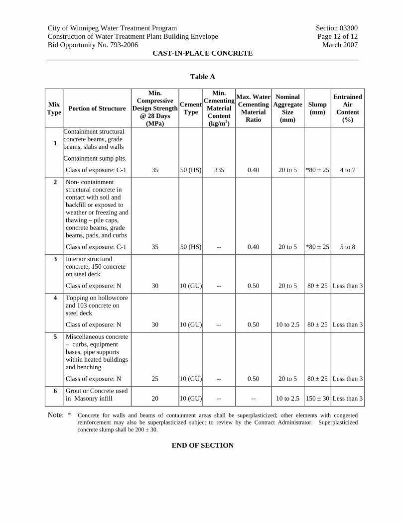
Table A
Mix Type Portion of Structure
Min. Compressive
Design Strength @ 28 Days
(MPa)
Cement Type
Min. Cementing Material Content (kg/m3)
Max. Water Cementing Material
Ratio
Nominal Aggregate
Size (mm)
Slump (mm)
Entrained Air
Content (%)
1
Containment structural concrete beams, grade beams, slabs and walls
Containment sump pits.
Class of exposure: C-1 35 50 (HS) 335 0.40 20 to 5 *80 ± 25 4 to 7
2 Non- containment structural concrete in contact with soil and backfill or exposed to weather or freezing and thawing – pile caps, concrete beams, grade beams, pads, and curbs
Class of exposure: C-1 35 50 (HS) -- 0.40 20 to 5 *80 ± 25 5 to 8
3 Interior structural concrete, 150 concrete on steel deck
Class of exposure: N 30 10 (GU) -- 0.50 20 to 5 80 ± 25 Less than 3
4 Topping on hollowcore and 103 concrete on steel deck
Class of exposure: N 30 10 (GU) -- 0.50 10 to 2.5 80 ± 25 Less than 3
5 Miscellaneous concrete – curbs, equipment bases, pipe supports within heated buildings and benching
Class of exposure: N 25 10 (GU) -- 0.50 20 to 5 80 ± 25 Less than 3
6 Grout or Concrete used in Masonry infill 20 10 (GU) -- -- 10 to 2.5 150 ± 30 Less than 3
Note: * Concrete for walls and beams of containment areas shall be superplasticized; other elements with congested reinforcement may also be superplasticized subject to review by the Contract Administrator. Superplasticized concrete slump shall be 200 ± 30.
END OF SECTION
City of Winnipeg Water Treatment Program Section 04051 Construction of Water Treatment Plant Building Envelope Page 1 of 4 Bid Opportunity No. 793-2006 March 2007
MASONRY PROCEDURES
1. GENERAL
1.1 Quality Control
.1 Conform to requirements of CSA A370, CSA A371 and design requirements of CSA S304.1 except where more stringent requirements are noted and/or indicated on Drawings and specified herein.
.2 Provide for compartments in long cavity wall and at corners to achieve appropriate pressure equalization and drainage in cavity wall design.
.3 Engineered Masonry: Conform to CSA A371 and CAN3-S304.1 and to details as indicated on structural Drawings.
1.2 Samples
.1 Submit duplicate full-size units samples or samples of size indicated, of each type of products specified for the Work, cured and finished in manner specified, and physically identical with material or product selected, and that show full range of color and texture variations expected.
.1 Masonry Units: Full size units.
.2 Stone Units: Random size units.
.3 Masonry Accessories: 300 mm (12”) long.
.4 Masonry Reinforcement, Ties and Corners: 300 mm (12”) long, or full size sample.
.5 Coloured Mortar: 150 mm (6”) long
1.3 Test Reports
.1 Submit triplicate copies of test reports.
.1 Masonry Units and Mortar Ingredients: Certifying compliance of masonry units and mortar ingredients with specification requirements.
1.4 Sample Installation
.1 Provide a 3 m x 3 m (10' x 10') representative sample installation of work of this Section On-Site at location directed by Contract Administrator to verify selections made under sample submittals and to demonstrate aesthetic effects and set quality standards for fabrication and installation.
.1 Showing masonry colours and textures, use of reinforcement, ties, through-wall flashing, weep holes, jointing, coursing, mortar and workmanship.
City of Winnipeg Water Treatment Program Section 04051 Construction of Water Treatment Plant Building Envelope Page 2 of 4 Bid Opportunity No. 793-2006 March 2007
MASONRY PROCEDURES
.2 Incorporate cavity insulation and air barrier specified in other Sections.
.2 Remove rejected sample installation and provide additional sample installations until acceptance is given. Do not commence Work until sample installation has been accepted. Accepted sample installation will not form part of the completed Work. Remove as directed by Contract Administrator.
.3 Acceptance of sample installations does not constitute acceptance of deviations from the Contract Documents contained in sample installations unless such deviations are specifically accepted by Contract Administrator in writing.
.4 Allow seventy two (72) hours for review of sample installation by Contract Administrator before proceeding with Work.
1.5 Delivery, Storage And Handling
.1 Deliver materials to Job Site in dry condition.
.2 Keep materials dry until use.
.3 Store under waterproof cover on pallets or plank platforms held off ground by means of plank or timber skids.
1.6 Environmental Requirements
.1 Cold Weather Requirements: Supplement CSA-A371 with following requirements:
.1 Maintain temperature of mortar between 5°C and 50°C until batch is used.
.2 Hot Weather Requirements
.1 Protect freshly laid masonry from drying too rapidly, by means of waterproof, non-staining coverings.
.2 Keep masonry dry using waterproof, non-staining coverings that extend over walls and down sides sufficient to protect walls from wind driven rain, until masonry work is completed and protected by flashings or other permanent construction.
.3 Protect masonry and other work from marking and other damage. Protect completed work from mortar droppings. Use non-staining coverings.
.4 Provide temporary bracing of masonry work during and after erection until permanent lateral support is in place.

City of Winnipeg Water Treatment Program Section 04051 Construction of Water Treatment Plant Building Envelope Page 3 of 4 Bid Opportunity No. 793-2006 March 2007
MASONRY PROCEDURES
2. PRODUCTS (NOT USED)
3. EXECUTION
3.1 Installation
.1 Do masonry work in accordance with CSA-A371 except where specified otherwise.
.2 Build masonry plumb, level, true to line, with vertical and horizontal joints in alignment.
.3 Layout coursing and bond to achieve correct coursing heights, and continuity of bond above and below openings, with minimum of cutting.
3.2 Construction
.1 Exposed Masonry: Remove chipped, cracked, and otherwise damaged units in exposed masonry and replace with undamaged units.
.2 Jointing:
.1 Concave Joints: Allow mortar to set just enough to remove excess water, then tool with round jointer to provide smooth, joints true to line, compressed, uniformly concave joints.
.2 Flush Joints: Strike flush all joints concealed in walls and joints in walls to receive plaster, tile, insulation, or other applied material except paint or similar thin finish coating.
.3 Cutting
.1 Cut out for electrical switches, outlet boxes, and other recessed or built-in objects.
.2 Make cuts straight, clean, and free from uneven edges.
.4 Building-In
.1 Build in items required to be built into masonry.
.2 Prevent displacement of built-in items during construction. Check plumb, location and alignment frequently, as work progresses.
.3 Brace door jambs to maintain plumb. Fill spaces between jambs and masonry with mortar.
.5 Support of Loads
.1 Use concrete to requirements of Division 3 Section 03300 – Cast-in-Place Concrete, where concrete fill is used in lieu of solid units.
City of Winnipeg Water Treatment Program Section 04051 Construction of Water Treatment Plant Building Envelope Page 4 of 4 Bid Opportunity No. 793-2006 March 2007
MASONRY PROCEDURES
.2 Use grout to CSA A179 where grout is used in lieu of solid units.
.3 Install building paper below voids to be filled with concrete or grout; keep paper 25 mm (1”) back from faces of units.
.6 Provision for movement
.1 Leave 12 mm (1/2”) space below shelf angles.
.2 Leave minimum 19 mm (3/4”) mm space or as indicated on Drawings between top of non-load bearing walls and partitions and structural elements. Do not use wedges.
.3 Built masonry to tie in with stabilizers, with provision for vertical movement.
.7 Loose steel lintels
.1 Install loose steel lintels. Centre over opening width.
.8 Cavity Walls
.1 Construct cavity walls with cavity free of mortar. Strike mortar joints in both wythes flush at cavity faces.
.9 Control joints
.1 Construct continuous control joints as indicated.
.10 Expansion joints
.1 Build-in continuous expansion joints as indicated.
.11 Site Tolerances
.1 To CSA-A371.
END OF SECTION
City of Winnipeg Water Treatment Program Section 04060 Construction of Water Treatment Plant Building Envelope Page 1 of 3 Bid Opportunity No. 793-2006 March 2007
MASONRY MORTAR AND GROUT
1. GENERAL
1.1 General Requirements
.1 Conform to requirements of Division 4 Section Masonry Procedures.
1.2 Quality Control
.1 Do mortar and grout work in accordance with CSA A179 except where specified otherwise.
.2 Use same brands of materials and source of aggregate for entire project.
.3 Irregularity in mortar joints for wall faces exposed or painted in the completed work: Not be noticeable when viewed from a distance of 4500 mm (15'-0").
2. PRODUCTS
2.1 Materials
.1 Use same brands of materials and source of aggregate for entire project.
.2 Colour additives: Non-staining, non-fading, ground coloured natural aggregates or metallic oxide pigments.
.3 Aggregate: CSA A179, except that the maximum allowable percentage passing 600 µm (No. 30) sieve shall be 80% and maximum passing 300 um (No. 50) sieve shall be 50%.
.4 Cement: Normal Portland, CAN/CSA-A5.
.5 Hydrated Lime: ASTM C207; Type S.
.6 Integral Water Repellent Admixture For Exterior Concrete Masonry Units and Concrete Mortar: Liquid polymeric admixture mixed with concrete during manufacture of concrete masonry units and added to mortar during mortar mixing in accordance with Manufacturer’s recommendations. Integral water repellent admixture system shall provide Class E Rating when tested in accordance with ASTM E514. Dry Block System by WR Grace.
2.2 Mortar Types
.1 Mortar for interior and exterior masonry above grade: CSA A179.
.1 Non-Loadbearing: Type N.
.2 Mortar for Stone Masonry Units: 1 part Portland cement, 1 part hydrated lime, 6 parts aggregate by volume.
.3 Grout: CSA A179, Table 3.
City of Winnipeg Water Treatment Program Section 04060 Construction of Water Treatment Plant Building Envelope Page 2 of 3 Bid Opportunity No. 793-2006 March 2007
MASONRY MORTAR AND GROUT
.4 Parging Mortar: Type N.
2.3 Mixes
.1 Measure and mix mortar materials based on CSA A179 Proportion Specifications.
.2 Use Portland cement in mortar for exterior masonry work and masonry cement for interior masonry work.
.3 Incorporate admixtures into mixes in accordance with Manufacturer's instructions.
.4 Do not mix different types of mortar or grout in the same mixer unless the mixer is thoroughly cleaned first.
.5 Type N Mortar: At Contractor’s option, one of the following:
.1 Pre-mixed mortar: CSA A179, Portland cement/lime/aggregate, Type N, by St. Lawrence Cement Company, Canada Cement, St. Mary Cement or Lake Ontario Cement Ltd. Mix, use and store in accordance with Manufacturer's instructions to produce small batches for immediate use only. Discard mixed mortar after 2 hours.
.2 Site silo mix: CSA A179, Portland cement/lime/aggregate, Type N, by Mega-Mix Ltd. or Max-Mix Ltd. or Jiffy Concrete Products. Mix required amount from Site silo as required. Take representative samples for testing consistency of strength in accordance with CSA A179. Use mortar within two hours after mixing at temperature of 26°C (79°F), or 2 1/2 hours at temperatures under 10°C (50°F).
.6 Pointing Mortar: Prehydrate pointing mortar by mixing ingredients dry, then mix again adding just enough water to produce damp unworkable mix that will retain its form when pressed into ball. Allow to stand for not less than 1 hour nor more than 2 hours then remix with sufficient water to produce mortar of proper consistency for pointing.
.7 Coloured Mortars: Use clean mixer for coloured mortar. Use colour additives not exceeding 10% of cement content by mass to produce coloured mortar to match architectural concrete block units.
3. EXECUTION
3.1 Application
.1 Do masonry mortar and grout work in accordance with CSA A179 except where specified otherwise.
.2 Parging: Apply parging in uniform coating not less than total 10 mm (3/8”) thick.
3.2 Repointing
.1 Repoint defective joints.
City of Winnipeg Water Treatment Program Section 04060 Construction of Water Treatment Plant Building Envelope Page 3 of 3 Bid Opportunity No. 793-2006 March 2007
MASONRY MORTAR AND GROUT
.2 Cut back joints 13 mm (1/2”) taking care not to damage units. Remove dust and loose materials by brushing or by water jet. If water jet is used, allow excess water to drain before repointing.
.3 Repoint with same mix and colour as original.
.4 Pack mortar tightly in thin layers, and tool joint to match non defective joints.
END OF SECTION

City of Winnipeg Water Treatment Program Section 04080 Construction of Water Treatment Plant Building Envelope Page 1 of 3 Bid Opportunity No. 793-2006 March 2007
MASONRY REINFORCEMENT AND CONNECTORS
1. GENERAL
1.1 General Requirements
.1 Conform to requirements of Section 04051 – Masonry Procedures.
1.2 Source Quality Control
.1 Upon request, provide Contract Administrator with certified copy of mill test report of reinforcement steel and connectors, showing physical and chemical analysis, minimum twenty five (25) calendar days prior to commencing reinforcement work.
2. PRODUCTS
2.1 Materials
.1 Acceptable Products: Subject to compliance with requirements of this Section, products that may be incorporated into the Work include, but are not limited to, the products specified. Products by other manufacturers similar in function, design, performance, and construction may be used subjected to Contract Administrator’s prior acceptance.
.2 Corrosion Protection: Steel reinforcing, ties, anchors and connectors and fasteners.
.1 Interior Side of Building Air Barrier: Hot dipped galvanized after fabrication to ASTM A153 B2 coating weight 457 gm/m2 (1.5 oz/ ft2).
.2 Exterior Side of Building Air Barrier and Parts of Exterior Wall: Type 304 stainless steel, ASTM A167 for plates, ASTM A580 for wires.
.3 Reinforcing Bar: CSA G30.18, Grade 400, deformed billet steel bars.
.4 Horizontal Reinforcement for Single Wythe Masonry: CSA A371, truss design, 3.66 mm stainless steel longitudinal and diagonally formed cross wires, DA3100 by Dur-O-Wal Limited or BL30 by Blok-Lok Limited. Width of reinforcing unit shall be 50 mm less than the nominal thickness of the wall. Provide prefabricated corners and tees.
.5 Cavity Wall Ties, Concrete Block Back Up: Engineered ties, properly sized, consisting of 1.6 mm (0.060”) thick stainless steel connector plate, 4.76 mm (0.19”) diameter stainless steel v ties, and polyethylene insulation support, Block Shear Connector by Fero Corp.
.1 Concrete Block Back Up Wythe: Two wire ladder horizontal reinforcing of 3.66 mm diameter stainless steel side and cross wires.
.6 Cavity Wall Ties, Concrete Back Up: Engineered ties, properly sized, consisting of 1.6 mm (0.060”) thick stainless steel L plate, 4.76 mm (0.19”) diameter stainless steel v ties, and polyethylene insulation support, Heavy Duty Rap-Tie by Fero Corp.
City of Winnipeg Water Treatment Program Section 04080 Construction of Water Treatment Plant Building Envelope Page 2 of 3 Bid Opportunity No. 793-2006 March 2007
MASONRY REINFORCEMENT AND CONNECTORS
.7 Top of Partition Lateral Supports: 10 mm (3/8) steel dowel welded to 2.75 mm (12 gauge) steel base plate with adjustment slots, hot dip galvanized, complete with dowel plastic sleeves and attaching hardware, Masonry Wall-Top Stabilizing Anchor by Dur-O-Wal. Supply and install horizontal soft joint continuously between top of masonry and underside structure. Soft Joint to be closed cell neoprene material conforming to ASTM D1056 class RE 41.
.8 Supply and Install stainless steel wall ties for all concrete masonry wall ends abutting concrete wall and column structure. Wall ties to be site installable and anchored to concrete structure with accepted stainless steel concrete anchors, Adjustable Wall Tie D/A 210 50mm x 200mm long by Dur-O-Wal.
3. EXECUTION
3.1 Installation
.1 Do work in accordance with CSA-A370, CSA-A371, and CSA-S304.1 unless indicated otherwise.
.2 Prior to placing concrete or grout, obtain Contract Administrator's approval of placement of reinforcement and connectors.
.3 Reinforce masonry walls and partitions with continuous reinforcement in every second block. Provide continuous reinforcing. In cavity wall extend reinforcing from interior masonry, spanning over cavity, into masonry veneer facing.
.4 Adjustable masonry reinforcement not permitted to correct poorly laid masonry. Bending of masonry reinforcement or ties not permitted.
.5 At corners of openings provide extra reinforcement, so that first and second courses above and below openings are reinforced. Extend extra reinforcement 600 mm beyond opening in each direction.
.6 Concrete Wall Backups: Space anchors at maximum 600 mm (24”) each direction, aligned vertically and horizontally.
.7 Cavity Wall Ties, Concrete Block Back Up: Space ties at 800 mm (32”) horizontally and 400 mm (16”) vertically. Place horizontal reinforcing in back up wythe 400 mm (16”) vertically in alternatives course to ties.
.8 Apply insulation retainer at each ties progressively as cavity wall insulation is installed. Ensure retainer presses insulation in tight and firm contact with air barrier.
.9 Top of Partition Lateral Supports: Mechanically anchor or weld supports to underside of structure, engage supports in full mortar in grooves in sash blocks or head joints. Space supports at 1800 mm (6'-0") oc.
City of Winnipeg Water Treatment Program Section 04080 Construction of Water Treatment Plant Building Envelope Page 3 of 3 Bid Opportunity No. 793-2006 March 2007
MASONRY REINFORCEMENT AND CONNECTORS
3.2 Field Touch-Up
.1 Touch up damaged and cut ends of galvanized reinforcement steel and connectors with compatible finish to provide continuous coating.
END OF SECTION
City of Winnipeg Water Treatment Program Section 04090 Construction of Water Treatment Plant Building Envelope Page 1 of 2 Bid Opportunity No. 793-2006 March 2007
MASONRY ACCESSORIES
1. GENERAL
1.1 General Requirements
.1 Conform to requirements of Division 4 Section 04051 – Masonry Procedures.
2. PRODUCTS
2.1 Materials
.1 Acceptable Products: Subject to compliance with requirements of this Section, products that may be incorporated into the Work include, but are not limited to, the products specified. Products by other manufacturers similar in function, design, performance, and construction may be used subjected to Contract Administrator’s prior acceptance.
.2 Control Joint Filler: Purpose-made, rubber, size and shape to suit end use as recommended by manufacturer, Rapid Control Joint by Dur-O-Wal.
.3 Dampproof Course and Flashing: Self-adhering modified bitumen membrane reinforced with proprietary polymer facing, minimum thickness 1 mm (40 mils), complete with manufacturer recommended primer and lap adhesive, compatible with air barrier system specified in Division 7 Section Air Barrier, Bueskin TWF Flashing System by Bakor.
.4 Weep Hole Vent: Cellular plastic, one-piece, flexible extrusion made from UV-resistant polypropylene copolymer, full height and width of mortar joint and depth 3 mm (1/8”) less than depth of outer wythe, in color selected from manufacturer's standard.
.5 Mortar Dropping Control Device: Mor-Control by Dur-O-Wal, full thickness of cavity wall air space.
3. EXECUTION
3.1 Installation – Control Joints And Expansion Joints
.1 Control Joints: Provide control joint fillers in interior and exterior masonry walls as indicated on Drawings and where wall height changes; where wall direction changes; where wall thickness changes; at pipe and column chases; at bond beam breaks; at abutments of columns and walls; at abutment of cold walls to warm walls; at openings in walls such as doors and windows; and at intervals in continuous walls as follows:
.1 Up to 2400 mm (8’) high: 9000 mm (30’) to 10500 mm (35’) oc.
.2 2400 mm (8’) to 3600 mm (12’) high: 10500 mm (35’) to 12000 mm (40’) oc.
.3 Over 3600 mm (12’) high: 12000 mm (40’) to 13500 mm (45’) oc.
City of Winnipeg Water Treatment Program Section 04090 Construction of Water Treatment Plant Building Envelope Page 2 of 2 Bid Opportunity No. 793-2006 March 2007
MASONRY ACCESSORIES
.2 Expansion Joints: Provide expansion joints within wall construction in locations indicated on Drawings. Provide joints to receive sealants specified in Division 7 Section Sealant.
3.2 Installation - Weep Hole Vents
.1 Install weep hole vents in vertical joints immediately over flashings, in exterior wythes of cavity wall and masonry veneer wall construction, at maximum horizontal spacing of 600 mm (24”) oc.
.2 Ensure that holes in vents are not plugged with mortar or debris.
.3 At walls higher than 2.8 m, provide second course at 2’-8’ centres.
3.3 Installation – Dampproof Course And Flashing
.1 Install dampproof courses and flashings where indicated on Drawings. If not fully indicated, install in the following locations
.1 Exterior Walls, General: Install flashings and dampproofing courses to provide continuous waterproofing flashing.
.2 Interior Walls on Slabs on Grade: Below first masonry course, full thickness of wythe.
.3 Intersection of Masonry Walls With Roofs or Other Exterior, Horizontal Surfaces: Immediately above roof flashing or horizontal surface flashing and seal to roof, horizontal flashing and air barrier.
.4 Cavity Walls: Full thickness of exterior wythe, horizontally across cavity and through insulation to terminate shingle style with minimum 150 mm (6") vertical leg behind air barrier. Maintain integrity of air barrier without damaging flashing, membrane and insulation.
.5 Non-Cavity Wall: Full thickness of wall.
.6 Wall Openings: Install work over openings in walls, extend past opening minimum of 200 mm (8") and turn up minimum 150 mm (6") at each end to create waterproof dam to prevent water draining into openings.
3.4 Installation – Mortar Dropping Control Devices
.1 Place mortar dropping control device in air space of cavity walls horizontally starting 200 mm (8”) above the damp proof course and extended full height of wall. Space devices at maximum 800 mm (32”) horizontally and 400 mm (16”) vertically. Stagger 50% on the horizontal joint from the previous unit.
.1 Ensure mortar droppings are kept to a minimum and do not bridge air space as wythe is erected.
END OF SECTION
City of Winnipeg Water Treatment Program Section 04220 Construction of Water Treatment Plant Building Envelope Page 1 of 3 Bid Opportunity No. 793-2006 March 2007
CONCRETE MASONRY UNITS
1. GENERAL
1.1 General Requirements
.1 Conform to requirements of Section 04051 – Masonry Procedures.
2. PRODUCTS
2.1 Materials
.1 Use normal weight concrete masonry units where finished face exposed to exterior or to earth below grade, or forming part of an exterior wall.
.1 S or SC/15/A/M: Solid block walls exposed to weather, and for other load bearing walls indicated.
.2 H/15/A/M: Locations where structural members bear on concrete block, and where indicated on Drawings: Fill units solid for top 2 courses of load bearing walls.
.2 Where concrete masonry walls are required to act as fire separations or barriers, provide units conforming to the building code with respect to classification, thickness, fire resistant ratings and type of concrete.
.3 Special Shapes: Provide bull-nosed and double bull nosed units for exposed corners. Provide purpose-made shapes for lintels and bond beams. Provide additional special shapes as indicated.
2.2 Concrete Masonry Units
.1 Standard Concrete Block Units: CAN3-A165 Series, modular size.
.2 Architectural Concrete Block Units: CAN3-A165 Series, modular size, integral water repellent treated to yield resistance to water penetration for 62 hours when tested to ASTM E514, No. 305 Charcoal Smooth Face by CCI Industries.
3. EXECUTION
3.1 Installation - Concrete Masonry Units
.1 Lay block to align plumb over each other with thick ends of webs up. Leave no cells open in exposed work.
.2 Minimize cutting block. Cut exposed block with power driven abrasive cutting disc or diamond cutting wheel where cutting is required and for flush mounted electrical outlets, grilles, pipes, conduit, leaving 3 mm (1/8”) maximum clearance.
City of Winnipeg Water Treatment Program Section 04220 Construction of Water Treatment Plant Building Envelope Page 2 of 3 Bid Opportunity No. 793-2006 March 2007
CONCRETE MASONRY UNITS
.3 Do not wet concrete masonry before or during laying in wall.
.4 Bond:
.1 Running Bond: Stagger end joints in every course. Align joints plumb over each other in every other course.
.2 Stack Bond: Align joints plumb over each other in every course.
.5 Buttering corners of units, throwing mortar droppings into joints, deep or excessive furrowing of bed joints will not be permitted. Do not shift or tap units after mortar has taken initial set. Where adjustment must be made after mortar has started to set, remove mortar and replace with fresh supply.
.6 Lay all joints approximately 10 mm (3/8”) thick unless otherwise specified or otherwise indicated on Drawings. Fill joints full of mortar except where specifically designated to be left open.
.7 Jointing: When mortar is thumb print hard, tool joints slightly concave for exposed work; elsewhere, strike joints flush. Use sufficient force to press mortar tight against masonry units on both sides of joints. Remove excess material or burrs left after jointing. Use trowel or rub with burlap bag.
.8 Locate corners accurately.
.9 Use bullnose and double bullnose block at sills and all external corners from second bottom course to top of partition where block is left exposed.
.10 Use square nose units at bottom course at external corner. Grind smooth corners to match bullnose units above, from top of flooring base.
.11 Use full bed of mortar for first course. For remaining courses bed face shells and cross and end webs and vertical end joints fully in mortar. Compress end joint mortar.
.12 Bond intersecting block walls in alternate courses with metal anchors. Where blockwork abuts concrete, bond each block course with site installed anchors.
.13 Do not break bond of walls of exposed units where partitions intersect and if bonding would show through on exposed face of walls. Bond these partitions, to walls they intersect, with prefabricated intersection masonry anchor reinforcement in each course.
3.2 Non-Load Bearing Partitions
.1 Non-Loading Bearing Partitions: Extend partitions in areas without suspended ceilings and other partitions indicated on Drawings, up through ceiling to structure above, unless indicated or specified otherwise: Terminate partitions minimum 19 mm (3/4") or as shown on Drawings, below structure and fill space between top of masonry and structure with compressible packing insulation.
City of Winnipeg Water Treatment Program Section 04220 Construction of Water Treatment Plant Building Envelope Page 3 of 3 Bid Opportunity No. 793-2006 March 2007
CONCRETE MASONRY UNITS
.2 Terminate remainder of masonry partitions minimum of 100 mm (4") above finished suspended ceilings.
3.3 Installation - Concrete Block Lintels
.1 Install reinforced concrete block lintels over openings in masonry where steel or reinforced concrete lintels are not indicated.
.2 End bearing: Not less than 200 mm (8”).
3.4 Cleaning
.1 Standard and Architectural Units: Allow mortar droppings on masonry to partially dry then remove by means of trowel, followed by rubbing lightly with small piece of block and finally by brushing.
.2 Pointing: Clean block faces using soft cloths before mortar hardens rake to 10 mm (3/8”). After completion of block laying fill joints with pointing mortar then point to provide concave joints. Repeat cleaning of faces.
END OF SECTION

City of Winnipeg Water Treatment Program Section 04230 Construction of Water Treatment Plant Building Envelope Page 1 of 2 Bid Opportunity No. 793-2006 March 2007
STONE MASONRY UNITS
1. GENERAL
1.1 General Requirements
.1 Conform to requirements of Division 4 Section 04051 – Masonry Procedures.
2. PRODUCTS
2.1 Materials
.1 Acceptable Products: Subject to compliance with requirements of this Section, products that may be incorporated into the Work include, but are not limited to, the products specified. Products by other manufacturers similar in function, design, performance, and construction may be used subjected to Contract Administrator’s prior acceptance.
.2 Stone, General: Hard, durable, well seasoned and of uniform strength, colour and texture, free of harmful quantities of radiation, or other mineral or organic defects.
.1 Limestone: ASTM C568, smooth face, ashlar course, random lengths and heights, 90 to 100 mm bed thickness, 200 mm course heights, Tyndall Limestone buff colour by Gillis Quarries Limited.
3. EXECUTION
3.1 Installation
.1 Clean stone by washing with water before laying.
.2 Lay heavy stones and projecting stones after mortar in courses below has hardened sufficiently to support weight.
.3 Prop and anchor projecting stones until wall above is set.
.4 Set large stones on water soaked softwood wedges to support stone in proper alignment until mortar has set. Remove wedges when dry, do not break off, grout holes with matching mortar.
.5 Remove mortar droppings and splashings from face of stone before mortar is set. Sponge stone free of mortar along joints as work progresses.
.6 Tool joints after initial set has occurred to concave finish.
.7 Arrange random coursed ashlar stone pattern so that no vertical joint is higher than highest course height being used, no horizontal joint is more than five stones long and no two stones of same height are placed end to end. End stones 100 mm long.

City of Winnipeg Water Treatment Program Section 04230 Construction of Water Treatment Plant Building Envelope Page 2 of 2 Bid Opportunity No. 793-2006 March 2007
STONE MASONRY UNITS
3.2 Cleaning
.1 After mortar has completely set brush stone work with stiff brush using mild alkaline abrasive cleaner that contains no caustic or harsh fillers.
.2 Rinse with clear water to remove foreign matter.
END OF SECTION
City of Winnipeg Water Treatment Program Section 05500 Construction of Water Treatment Plant Building Envelope Page 1 of 5 Bid Opportunity No. 793-2006 March 2007
METAL FABRICATIONS
1. GENERAL
1.1 Design Requirements
.1 Design details and connections, where not shown on Drawings, in accordance with CAN/CSA-S16, CSA S136, and CSA S136.1.
.2 All metal fabrications to be hot dipped galvanized unless noted otherwise on the Drawings or elements fabricated from stainless steel.
1.2 Quality Control
.1 Retain a Professional Engineer registered in the Province of Manitoba, with experience in work of comparable complexity and scope, to perform the following services as part of the Work of this Section:
.1 Design metal fabrication items as required to resist live, dead, lateral, wind, and seismic loads.
.2 Structural design.
.3 Review, stamp, and sign Shop Drawings.
.4 Conduct shop and Site inspections.
.5 Prepare and submit inspection reports.
.2 Do steel welding to CSA W59 by fabricators certified by the Canadian Welding Bureau to CSA W47.1.
1.3 Submittals
.1 Shop Drawings and design briefs are to be signed and sealed by a Professional Engineer registered in the Province of Manitoba.
.2 Shop Drawings shall show work of this Section including large scale detail of members and materials, of connection and jointing details, and of anchorage devices, dimensions, thicknesses, description of materials, metal finishing, as well as other pertinent data and information.
2. PRODUCTS
2.1 Materials
.1 Structural Steel: CAN/CSA-G40.21; Type W with minimum yield strength of 300 MPa.
.2 Hollow Structural Steel Sections: CAN/CSA-G40.20/G40.21-M, Grade 350W, Class C.

City of Winnipeg Water Treatment Program Section 05500 Construction of Water Treatment Plant Building Envelope Page 2 of 5 Bid Opportunity No. 793-2006 March 2007
METAL FABRICATIONS
.3 Galvanized Sheet Steel: ASTM A653/A653M Grade A, Z275 Commercial Quality zinc coating, size and shape as shown.
.4 Fasteners: Bolts, nuts, washers, rivets, lock washers, anchor bolts, machine screws and machine bolts hot dipped galvanized to CSA G164. For joining stainless steel components use stainless steel fasteners.
.5 Primer Paint: CISC/CPMA 2-75.
.6 Galvanizing: conforming to CAN/CSA-G164; minimum 610 g/m2.
.7 Galvanized Primer Paint: Organic zinc rich primer. For galvanized fabrications where touchup is to remain unpainted in finished work: Inorganic zinc rich primer, Galvafroid by W.R. Meadows of Canada Ltd.
.8 Grout: Non-shrink, non-metallic, flowable, 1-day 15 MPa (2100 psi) compressive strength, pull-out strength 7.9 MPa (1150 psi).
.9 Drilled Anchors: HY-150 Adhesive anchors with stainless steel rods by Hilti Inc., sizes to suit.
2.2 Fabrication
.1 Verify dimensions of installed Work before commencing fabrications and report any discrepancies to Contract Administrator.
.2 Fit and assemble Work in shop where possible. Execute work in accordance with details and reviewed Shop Drawings. Where shop fabrication is not possible, make trial assembly in shop.
.3 Seal exterior steel fabrications against corrosion in accordance with CAN/CSA S16.1.
.4 Unless indicated otherwise, provide welded connection for work of this Section.
.5 Carefully make and fit details. Take special care with exposed finished Work to produce a neat and correct appearance to Contract Administrator’s acceptance.
.6 Assemble members without twists or open joints.
.7 Correctly size holes for connecting Work of other Sections where such can be determined prior to fabrication. Where possible, show holes on shop drawings. Place holes not to cause appreciable reduction in strength of member.
2.3 Welding
.1 Perform welding by electric arc process.
.2 Execute welding to avoid damage or distortion to Work. Execute welding in accordance with following standards:
City of Winnipeg Water Treatment Program Section 05500 Construction of Water Treatment Plant Building Envelope Page 3 of 5 Bid Opportunity No. 793-2006 March 2007
METAL FABRICATIONS
.1 CSA W48: For welding materials. If rods are used, only coated rods are allowed.
.2 CSA W59: For design of connections and workmanship.
.3 CAN/CSA W117.2: For safety.
.3 Thoroughly clean welded joints and expose metals for a sufficient distance to perform welding operations.
.4 Test welds for conformance and remove work not meeting specified standards and replace to Contract Administrator’s acceptance.
.5 Continuous weld all joints for the full length of each joint. Finish exposed welds smooth and flush, file, or grind as required.
2.4 Anchors and Fastening
.1 Use weld studs of size not larger than 10 mm for attaching miscellaneous materials and equipment to building steel. If weight of item requires larger fasteners use clips or brackets and secure by welding or through bolting.
.2 Use self-drilling expansion type concrete anchors for attaching to masonry and concrete.
2.5 Inserts and Hangers
.1 Install inserts, hangers, and supports. Make inserts drilled type.
.2 Before openings are cut through structure, obtain Contract Administrator's written acceptance for procedures, locations and reinforcements required.
2.6 Shop Priming
.1 Clean steel to SSPC SP7 and remove loose mill scale, weld flux, and splatter in preparation for shop priming.
.2 Shop prime steel with one coat of primer paint to dry film thickness of 0.07 mm. Paint on dry surfaces, free from rust, scale, grease. Do not paint when temperature is lower than 7°C. Paint items under cover and leave under cover until primer is dry. Follow paint Manufacturer's recommendations regarding application methods, equipment, temperature, and humidity conditions.
.3 Clean but do not prime surfaces to be field welded.
.4 Do not prime surfaces embedded in concrete, clean as if they were to be primed.
.5 Do not prime machine finished surfaces, but apply an effective anti-rust compound.
.6 Take precautions to avoid damage to adjacent surfaces.
City of Winnipeg Water Treatment Program Section 05500 Construction of Water Treatment Plant Building Envelope Page 4 of 5 Bid Opportunity No. 793-2006 March 2007
METAL FABRICATIONS
2.7 Hot Dip Galvanizing
.1 Hot dip galvanize, after fabrication, steel metal fabrication items. Straighten shapes and assemblies true to line and plane after galvanizing. Repair damaged galvanized surfaces with brush or spray-applied anti-corrosion coating containing 92 to 95% zinc, in accordance with Manufacturer's printed directions.
.1 Members exposed to elements when in final location.
.2 Members embedded on exterior side of exterior walls.
.3 Members imbedded in concrete.
.4 Members specified in this Section or indicated on Drawings.
.2 Hot-dip galvanize members in accordance with CAN/CSA G164 and requirements of the following ASTM standards, with minimum coating weights or thicknesses as follows:
.1 Rolled, Pressed and Forged Steel Shapes, Plates, Bars and Strips: ASTM A123/A123M; average weight of zinc coating of actual surface
.1 4.8 mm (3/16”) and less member thickness: 600 g/m2
.2 6 mm (1/4”) and heavier members: 640 g/m2
.2 Iron and Steel Hardware: ASTM A153/A153M; minimum weight of zinc coating, in gram per square meter of surface, in accordance with Table 1 for the various classes of materials used in the Work.
3. EXECUTION
3.1 Erection
.1 Fit joints and intersecting members accurately. Make Work in true planes with adequate fastenings. Build and erect Work plumb, true, square, straight, level and accurate to sizes detailed, free from distortion or defects detrimental to appearance or performance.
.2 Perform drilling of concrete as required to fasten Work of this Section.
.3 Unless otherwise indicated, grout set work in concrete with non-shrink grout. Trowel surface smooth and flush with adjacent surfaces.
.4 Insulate metals where necessary to prevent corrosion due to contact between dissimilar metals and between metals and masonry, concrete or plaster. Use bituminous paint, butyl tape, building paper or other approved means.
.5 Obtain Contract Administrator’s written acceptance prior to field cutting or altering of structural members.
City of Winnipeg Water Treatment Program Section 05500 Construction of Water Treatment Plant Building Envelope Page 5 of 5 Bid Opportunity No. 793-2006 March 2007
METAL FABRICATIONS
3.2 Field Painting
.1 Paint bolt heads, washers, nuts, field welds and previously unpainted items. Touch up shop primer damaged during transit and installation, with primer to match shop primer.
END OF SECTION
City of Winnipeg Water Treatment Program Section 05530 Construction of Water Treatment Plant Building Envelope Page 1 of 4 Bid Opportunity No. 793-2006 March 2007
ALUMINIUM FABRICATIONS
1. GENERAL
1.1 Design Requirements
.1 Comply with CSA S157/A157.1 for strength design in aluminium work.
.2 Design railings, balustrade, and landing construction and connections to requirements of the building code and other authorities having jurisdiction. Maximum deflection of L/360 of clear span.
1.2 Quality Assurance
.1 Retain a Professional Engineer registered in the Province of Manitoba, with experience in work of comparable complexity and scope, to perform the following services as part of the Work of this Section:
.1 Structural design
.2 Review, stamp, and sign Shop Drawings
.3 Conduct shop and Site inspections
.4 Prepare and submit inspection reports
.2 Do welding to CSA W59.2. All Work is to be performed by a firm certified by the Canadian Welding Bureau to the requirements of CSA W47.2 in Division 2.
1.3 Submittals
.1 Shop Drawings and design briefs are to be signed and sealed by a Professional Engineer registered in the Province of Manitoba.
.2 Shop Drawings shall show work of this Section including large scale detail of members and materials, of connection and jointing details, and of anchorage devices, dimensions, thicknesses, description of materials, metal finishing, as well as other pertinent data and information.
2. PRODUCTS
2.1 Materials
.1 Aluminium Plates, Shapes and Extrusions: 6061-T6 alloy, anodizing quality.
.2 Fasteners: Stainless steel ASTM type 316 for all bolts, nuts, washers, rivets, lock washers, anchor bolts, machine screws and machine bolts with appropriate isolation devices.
City of Winnipeg Water Treatment Program Section 05530 Construction of Water Treatment Plant Building Envelope Page 2 of 4 Bid Opportunity No. 793-2006 March 2007
ALUMINIUM FABRICATIONS
.3 Grout: Non-shrink, non-metallic, flowable, 1-day 15 MPa (2100 psi) compressive strength, pull-out strength 7.9 MPa (1150 psi).
.4 Bituminous Paint: to MPI (Master Paint Institute) EXT 5.4D, without thinner.
.5 Drilled Anchors: HY-150 Adhesive anchors with stainless steel rods by Hilti Inc., sizes to suit.
2.2 Aluminium Finishes
.1 Clear Anodic Finish: AA-M12C22A41, as fabricated nonspecular mechanical finish, medium matte etched chemical finish, architectural class I clear anodic coating of minimum 18 µm (0.7 mil) thick complying with AAMA 611.
2.3 Fabrication
.1 Verify dimensions of installed Work before commencing fabrications and report any discrepancies to Contract Administrator.
.2 Fit and assemble Work in shop where possible. Execute Work in accordance with details and reviewed Shop Drawings. Where shop fabrication is not possible, make trial assembly in shop.
.3 Supply and install bolted connections wherever possible. Bolted connections shall be bearing-type connections with the thread excluded from the planes of shear. Welded connections will not be permitted unless approved by the Contract Administrator. Inform Contract Administrator if required welding procedures will negatively influence the original yield strength of the members at the compression or tension flange. Adjust welding procedures as required by the Contract Administrator at no additional cost.
.4 Carefully make and fit details. Take special care with exposed finished Work to produce a neat and correct appearance to Contract Administrator’s acceptance.
.5 Assemble members without twists or open joints.
.6 Correctly size holes for connecting Work of other Sections where such can be determined prior to fabrication. Where possible, show holes on Shop Drawings. Place holes not to cause appreciable reduction in strength of member.
2.4 Welding
.1 Execute welding to avoid damage or distortion to Work. Execute welding in accordance with following standards:
.1 CSA W48: For welding materials. If rods are used, only coated rods are allowed.
.2 CSA W59.2: For design of connections and workmanship.
.3 CAN/CSA W117.2: For safety.
City of Winnipeg Water Treatment Program Section 05530 Construction of Water Treatment Plant Building Envelope Page 3 of 4 Bid Opportunity No. 793-2006 March 2007
ALUMINIUM FABRICATIONS
.2 Thoroughly clean welded joints and expose aluminium surfaces for a sufficient distance to perform welding operations.
.3 Test welds for conformance and remove work not meeting specified standards and replace to Contract Administrator’s acceptance.
.4 Continuous weld all joints for the full length of each joint. Finish exposed welds smooth and flush, file, or grind as required.
2.5 Anchors and Fastening
.1 Use weld studs of size not larger than 10 mm for attaching miscellaneous materials and equipment to building structure. If weight of item requires larger fasteners use clips or brackets and secure by welding or through bolting.
2.6 Inserts and Hangers
.1 Install inserts, hangers, and supports. Make inserts drilled type.
.2 Before openings are cut through structure, obtain Contract Administrator's written acceptance for procedures, locations, and reinforcements required.
3. EXECUTION
3.1 Damaged Members
.1 Repair or replace members damaged during transit or erection, before securing in position.
3.2 Erection
.1 Erect aluminum in accordance with CSA S157/A157.1 and Drawings.
.2 Field connections are to be bolted wherever possible. Field welding of aluminum will not be permitted unless approved by the Contract Administrator.
.3 Perform required field welding. Visible field welds to be smooth, grind or file as required. Touch up galvanizing as required.
.4 Obtain the Contract Administrator’s permission prior to Site cutting or making adjustments which are not part of the scheduled Work.
.5 Install items plumb, square and level; fit accurately, and maintain free from distortion or defects detrimental to appearance and performance.
.6 Make adequate provision for all erection loads, and for sufficient temporary bracing to maintain structure safe, plumb and in true alignment until completion of erection and installation of necessary permanent bracing.
City of Winnipeg Water Treatment Program Section 05530 Construction of Water Treatment Plant Building Envelope Page 4 of 4 Bid Opportunity No. 793-2006 March 2007
ALUMINIUM FABRICATIONS
.7 Set column bases and other vertical members to design elevations on levelling nuts or stainless steel wedges. Do not use wood wedges.
.8 Use only light drifting to draw parts together. Enlarge holes for bolted connections with reamers or twist drill only. Do not burn to form holes, enlarge holes or match unfair holes.
.9 Obtain Contract Administrator's written permission prior to field cutting or altering structural members.
.10 After erection field prime welds, nuts, bolts, washers and touch up abrasions and damage to bituminous coatings and galvanizing.
.11 Supply and Install anchors for setting in concrete with minimum 100 embedment.
.12 Paint aluminum surfaces in contact with concrete with two (2) coats of alkali-resistant bituminous paint.
.13 Prevent electrolysis between aluminum and dissimilar metals in contact with appropriate isolation devices.
END OF SECTION

City of Winnipeg Water Treatment Program Section 06100 Construction of Water Treatment Plant Building Envelope Page 1 of 3 Bid Opportunity No. 793-2006 March 2007
ROUGH CARPENTRY
1. GENERAL
1.1 Design Requirements
.1 Design construction methods for expansion and contraction of materials. Adopt method of construction to ensure that materials are rigidly and securely attached and will not be loosened by work of other Sections. Fasten wood nailers, blocking, framing and strapping solidly to adjacent materials in true planes.
1.2 Quality Control
.1 Lumber Identification: Lumber identification shall conform to requirements of Standard Grading Rules for Canadian Lumber of NLGA or grade stamped by an agency certified by Canadian Lumber Standards Accreditation Board.
.2 Plywood identification: by grade mark in accordance with applicable CSA standards.
.3 Align and plumb faces of furring and blocking to tolerance of 1:600.
1.3 Submittals
.1 Preservative Treatment Test Reports: Duplicate reports from chemical treatment Manufacturer and certification by independent testing agency comply with requirements. Indicate type of preservative used, net amount of preservative retained, and chemical treatment Manufacturer's written instructions for handling, storing, installing, and finishing treated material.
.2 For products receiving a waterborne treatment, include statement that moisture content of treated materials was reduced to levels specified before shipment to Project Site.
.3 Include copies of warranties from chemical treatment manufacturers for each type of treatment.
1.4 Waste Disposal
.1 Dispose waste legally off-site, in accordance with governing regulation. Dispose of any end-cuts and left over chemicals in an approved land-fill site. Do not burn or allow other use of end-cuts.
2. PRODUCTS
2.1 Materials
.1 Framing Lumber: Unless specified otherwise, Spruce/Pine/Fir (SPF), NLGA 121b Standard, with structural members meeting minimum No. 2 Grade requirements of CAN/CSA-O141.
City of Winnipeg Water Treatment Program Section 06100 Construction of Water Treatment Plant Building Envelope Page 2 of 3 Bid Opportunity No. 793-2006 March 2007
ROUGH CARPENTRY
.2 Cants, Curbs, Blocking, Nailers and other Members Less Than 89 mm (4") Wide: Spruce, 122c. "Standard" light framing, except as otherwise specified.
.3 Softwood Plywood, Douglas Fir, CSA O121-M of Following Grades: Good One Side (G1S) elsewhere.
.4 Rough Hardware: CSA B111; Nails, screws, bolts, lag screws, anchors, special fastening devices and supports required for erection of carpentry components. Use galvanized components if exposed to exterior atmosphere. Galvanize in accordance with requirements of CAN/CSA-G164-M.
.5 General purpose adhesive: CSA O112 Series.
.6 Proprietary fasteners: Toggle bolts, expansion shields and lag bolts, screws and lead or inorganic fibre plugs, explosive actuated fastening devices, recommended for purpose by Manufacturer.
2.2 Wood Preservative-Treated Materials
.1 Preservative Treatment by Pressure Process: CSA O80 Series, using preservative chemicals acceptable to authorities having jurisdiction, ammoniacal or amine copper quat (ACQ), or copper azole (AC), except that lumber that is not in contact with the ground and is continuously protected from liquid water may be treated with inorganic boron (SBX).
.2 Precut wood, where practical, prior to preservative treatment.
.3 Treat site cut pressure treated lumber cut ends treated with preservatives compatible with pressure treatment chemicals.
.4 Kiln-dry material after treatment to a maximum moisture content of 19% for lumber and 15% for plywood. Do not use material that is warped or does not comply with requirements for untreated material.
.5 Mark each treated item with the treatment quality mark of an inspection agency approved by the Canadian Lumber Standards Accreditation Board.
.6 Application: Treat items indicated on Drawings, and the following:
.1 Wood cants, nailers, curbs, equipment support bases, blocking, stripping, and similar members in connection with roofing, flashing, air and vapour barriers, and waterproofing.
.2 Wood sills, sleepers, blocking, furring, stripping, and similar concealed members in contact with masonry or concrete.
City of Winnipeg Water Treatment Program Section 06100 Construction of Water Treatment Plant Building Envelope Page 3 of 3 Bid Opportunity No. 793-2006 March 2007
ROUGH CARPENTRY
3. EXECUTION
3.1 Installation - General
.1 Install members true to line, levels and elevations.
.2 Construct continuous members from pieces of longest practical length.
.3 Install spanning members with crown-edge up.
.4 Install materials so that grade-marks and other defacing marks are not visible or are removed by sanding.
.5 Frame, anchor, fasten, tie and brace members to provide necessary strength and rigidity.
.6 Countersink bolts where necessary to provide clearance for other work.
.7 Fasten work to hollow units with toggle bolts and to solid masonry or concrete with lead expansion shields and lag screws. Do not use organic fibre or wood plugs.
3.2 Furring And Blocking
.1 Install furring and blocking as required to space-out and support casework, cabinets, wall and ceiling finishes, facings, fascia, soffit, siding and other work as required.
.2 Install furring to support siding applied vertically and where sheathing is not suitable for direct nailing.
3.3 Nailing Strips, Grounds ,and Rough Bucks
.1 Install rough bucks, nailers and linings to rough openings as required to provide backing for frames and other work.
3.4 Cants, Curbs, Fascia Backing
.1 Install wood cants, fascia backing, nailers, curbs and other wood supports as required and secure using galvanized fasteners.
END OF SECTION
City of Winnipeg Water Treatment Program Section 07210 Construction of Water Treatment Plant Building Envelope Page 1 of 2 Bid Opportunity No. 793-2006 March 2007 BUILDING INSULATIONS
1. GENERAL
1.1 General Requirements
.1 This Section specifies insulation Work not specified in other Sections. Refer to other Sections for the respective insulation requirements.
1.2 Delivery, Storage And Handling
.1 Deliver materials to Site in their original wrappings with labels intact and store in areas directed by Contract Administrator.
.2 Store insulation on raised platforms and protect with waterproof covers. Prevent exposure of insulation to UV exposure.
.3 Store materials inside buildings for 24 hours prior to installation.
2. PRODUCTS
2.1 Materials
.1 Cavity Wall Insulation: CAN/ULC S701 Type 3, expanded, extruded polystyrene board insulation, minimum compressive strength of 170 kPa (25 psi) at 10% deformation or yield; square edges; unfaced, Styrofoam Cavitymate Ultra by Dow Chemical of Canada Ltd.
.2 Mineral Wool Insulation, Soffit, and Miscellaneous Applications: CAN/ULC S702, Mineral fiber board insulation, CavityRock by Roxul or CWB 45 by Fibrex.
.3 Adhesive: Compatible to and as recommended by manufacturer of insulating materials.
.4 Cement Mortar Mix: 1 part Portland cement, 6 part masonry sand, 1 part hydrated lime, potable water to produce a workable mix.
.5 Mechanical Fasteners
.1 Insulation Clips: Impale type, perforated 50 mm x 50 mm (2" x 2") cold rolled steel adhesive back, spindle of length to suit insulation plus 25 mm (1") with speed washers.
.2 Nails: Galvanized steel, length 25 mm (1") longer than insulation thickness, CSA B111 Table 12.
.3 Staples: Galvanized wire, 12 mm (1/2") minimum.
.6 Z-Section Strapping: Roll-formed from minimum 0.63 mm (25 gauge) electro-galvanized sheet steel and having a 32 mm (1-1/4") minimum wide flanges and web depth to suit insulation thickness. Provide flanges knurled to facilitate acceptance of screws, and with rolled lips at outer edges for added stiffness.
City of Winnipeg Water Treatment Program Section 07210 Construction of Water Treatment Plant Building Envelope Page 2 of 2 Bid Opportunity No. 793-2006 March 2007 BUILDING INSULATIONS
3. EXECUTION
3.1 Preparation
.1 Ensure that surfaces to receive adhesive or insulation are dry, firm, straight, and free from loose material, projections, ice, frost, slick, grease, oil or other matter detrimental to bond of the adhesive or uniform bedding of the insulation.
.2 Maintain surface and ambient temperatures during application and curing of adhesive at a temperature recommended by the manufacturer of the type of adhesive used.
3.2 Installation - General
.1 Install insulation to maintain continuity of thermal protection to building elements and spaces as indicated on Drawings.
.2 Fit insulation tight to electrical boxes, plumbing and heating pipes and ducts, around exterior doors and windows and other projections or openings.
.3 Cut and trim insulation neatly to fit spaces. Butt joints tightly, offset vertical joints. Use only insulation panels free from ripped backs or chipped or broken edges.
.4 Install materials in accordance with manufacturer's instructions.
.5 Do not cover insulation until it has been reviewed by Contract Administrator.
3.3 Installation
.1 Apply adhesives to substrate at rate recommended by manufacturer.
.2 Fix insulation clip type fasteners on substrate, 2 per 600 mm x 1200 mm (24" x 48") board minimum. Impale insulation board on insulation clips, butting all joints firmly together and secure with washers, cut off spindles 3 mm (1/8") beyond washer.
.3 Leave insulation board joints unbonded over line of expansion and control joints. Bond a continuous 150 mm (6") wide 6 mil polyethylene strip over joint using compatible adhesive prior to application of insulation.
.4 Provide flexible insulation of equivalent thickness and thermal insulation to fit areas where application of rigid insulation is not possible to provide continuous coverage.
.5 Where gypsum board or other board finish is to be installed directly over insulation assembly, apply the z-section strapping, unless otherwise indicated, to the substrate using powder-activated or pneumatic fasteners. Arrange strapping to suit the fixing requirements of the board to be applied.
END OF SECTION

City of Winnipeg Water Treatment Program Section 07270 Construction of Water Treatment Plant Building Envelope Page 1 of 4 Bid Opportunity No. 793-2006 March 2007
AIR BARRIERS
1. GENERAL
1.1 Installers Qualifications
.1 Installers: Skilled mechanics having minimum 5 years experience in the Work specified and having an understanding of the design principles of air barrier. Must be trained by Manufacture or recognized body or association specializing in this field.
.2 The air barrier Contractor shall submit at time of tender copy of their Quality Control Program including daily testing and inspection in accordance with ASTM E 1186, ASTM D4541 and CMCH/OAA Guideline for Delivering Effective Air Barrier Systems. Daily records to be submitted on a weekly basis. The Air/Vapour Barrier shall be installed by one trade, and shall ensure continuity between all of the building envelope assemblies and systems.
.3 Pre-installation meeting: Before commencing the Work of this Section, arrange a Site meeting attended by the Contractor, this Section, the Contract Administrator, and the material manufacturers' qualified representative. Discuss surface conditions, application procedures, suitability of materials and alternative recommendations.
1.2 Submittals
.1 Samples: Two 150 mm x 150 mm (6" x 6") samples of sheet air barriers.
.2 Shop Drawings and Product Data submitted to the Contract Administrator at least 21 days before the preinstallation. No preinstallation conference will be held and no material shall be applied until submittals are complete and released for construction.
.3 Product Data: For each type of product indicated. Include technical data; certified test results; manufacturer's printed instructions for evaluating, preparing and treating substrate; and installation instructions, including temperature and other limitations of installation.
.4 Shop Drawings: Show locations and extent of air/vapor barrier and details of intersections with other envelope systems and materials; details of membrane counter-flashings; details for construction of inside and outside corners; and details showing how expansion and control joints will be bridged. Identify materials, primers, sealers, support materials and other items detailed, including manufacturer’s product names. Show relationship to adjacent materials, sequence of installation and materials, and methods for sealing penetrations. Shop drawing shall include connection details between the air/vapor barrier and for the following exterior envelope components as applicable to the project:
.1 Aluminum-framed entrances, storefronts and curtain walls.
.2 Wall and roof assemblies.
.3 Wall penetrations by pipes, ducts and conduits.
City of Winnipeg Water Treatment Program Section 07270 Construction of Water Treatment Plant Building Envelope Page 2 of 4 Bid Opportunity No. 793-2006 March 2007
AIR BARRIERS
.4 Control joint details in gypsum based sheathing, CMU, and plywood substrates, as applicable.
.5 Hollow metal door frames, mechanical louvers and vent penetrations.
.5 Product Certificates: For air/vapor barrier system, certifying compatibility of air/vapor barrier system and accessory materials with Project materials that connect to or that come in contact with the air/vapor barrier system; signed by product manufacturer.
.6 Qualification Data: For Installer signed by manufacturer certifying that Installers comply with requirements.
.7 Product Test Reports: From a qualified independent testing agency indicating and interpreting test results of air/vapor barrier system for compliance with requirements, based on comprehensive testing of current air/vapor barrier system in accordance with ASTM E 2178.
.8 Daily Reports: Installer shall maintain daily reports at the site. Copies of reports shall be submitted
1.3 Performance Requirements
.1 Air/Vapor Barrier: Shall be designed and constructed as a continuous air barrier to control air leakage into, or out of the conditioned space, and to act as a watertight barrier to discharge to the outside any incidental condensation or water penetration. Air/vapor barrier membrane shall accommodate movements of building materials by providing expansion and control joints as required, with appropriate air seal materials at such locations, changes in substrate and perimeter conditions.
.2 Barrier shall be continuous with all joints made air-tight and shall have the following characteristics: 1. Air Permeability Material: Shall not exceed 0.02 L/(s·m2) measured at an air pressure difference of 75 Pa.”when tested in accordance with ASTM E 283.
.3 Air Permeability of the Assembly: Shall not exceed 0.05 L/(s·m2) measured at an air pressure difference of 75 Pa.”when tested in accordance with ASTM E 283
.4 Shall be capable of withstanding positive and negative combined design wind, fan and stack pressures on envelope without damage or displacement; shall transfer load to structure; and shall not displace adjacent materials under full load.
1.4 Sample Installation
.1 Provide a one building module representative sample installation on-site at location directed by Contract Administrator. Include a sample of the condition of the barrier edge at concrete and at metal showing typical fastenings, a barrier to barrier joint and a deflection provision, at window junction. Modify or replace sample installations as directed to obtain approval. Accepted sample installation shall form the standard for remaining Work and may form part of the Work.

City of Winnipeg Water Treatment Program Section 07270 Construction of Water Treatment Plant Building Envelope Page 3 of 4 Bid Opportunity No. 793-2006 March 2007
AIR BARRIERS
1.5 Delivery, Storage, and Handling
.1 Deliver materials in factory wrapped rolls with labels indicating manufacturer and trade name, material type, thickness, roll width and area.
.2 Protect materials from direct exposure to sunlight and physical damage.
1.6 Coordination
.1 Coordinate installation of sheet air-vapour barrier with work of other Sections to achieve an air and vapour tight building envelope.
1.7 Quality Control
.1 Perform one adhesion test for each 100 sq.m., or fraction thereof, for wall area receiving work of this Section.
.2 Do adhesion test in accordance with ASTM D4541.
.1 Minimum result: 110 kPa
1.8 Quality Assurance
.1 The City may engage and pay for the services of a testing and inspection agency to perform tests in accordance with ASTM E783 and E1186.
2. PRODUCTS
2.1 Materials
.1 Air/Vapour Barrier Membrane: 1 mm (40 mils) thick modified bituminous composite sheet, Perm-A-Barrier by W.R. Grace Co. of Canada Ltd., Air-Shield by WR Meadows, or Sopraseal Stick 1100 by Soprema, complete with primer, mastic and liquid membrane as required.
3. EXECUTION
3.1 Installation - Air Barrier Membrane
.1 Install the membrane in strict accordance with the Manufacturer's written instructions and the representative's on Site instructions.
.2 Ensure complete coverage of and adhesion to all substrate to receive the air/vapour barrier membrane, including all wall protrusions. Extend membrane 150 mm (6") below top of foundation walls. Co-operate with other Sections to ensure continuity of the barrier.
City of Winnipeg Water Treatment Program Section 07270 Construction of Water Treatment Plant Building Envelope Page 4 of 4 Bid Opportunity No. 793-2006 March 2007
AIR BARRIERS
.3 Apply the membrane to primed substrate in 2400 mm (8') lengths or as recommended by the membrane Manufacturer.
.4 Apply membrane so that horizontal joints overlap with the upper sheet over the lower sheet, shingle style. Lap all horizontal joints minimum 50 mm (2") all side joints minimum 64 mm (21/2") and all end joints minimum 150 mm (6"). Stagger vertical joints to avoid four way joints.
.5 Apply a trowelled head of mastic to all terminations of the membrane at the end of a day's work and at membrane terminations.
.6 Reinforce all inside and outside corners with a continuous 300 mm (12") wide sheet membrane prior to installing the air/vapour barrier.
.7 Fill gaps and joints with liquid membrane and reinforce with a continuous 300 mm (12") wide sheet membrane prior to installing the air/vapour barrier.
.8 Use liquid membrane at all protrusions and difficult detail areas and provide a minimum 64 mm (21/2") overlap with the sheet membrane.
.9 Apply air/vapour barrier so that the exterior wall is air tight, with air tight junctures at openings, penetrations, and edges.
.10 Inspect air/vapour barrier for continuity immediately prior to installation of insulation. Do not cover the air/vapour barrier until it has been inspected.
.11 Repair punctures, rips and tears with pieces of membrane completely adhered to the damaged membrane.
.12 Where punctures and tears are extensive, replace entire damaged section.
.13 Install membrane over doors, windows, and other openings to exterior walls.
.14 At openings, extend membrane 200 mm (8") beyond jambs, heads and sills.
.15 Use mastic or fixing bars to adhere membrane to windows, doors etc. to maintain continuity of the barrier.
3.2 Inspection
.1 Do not cover any portion of the air-vapour barrier until it has been inspected by the Contract Administrator or by an inspection agency appointed by the Contract Administrator.
END OF SECTION
City of Winnipeg Water Treatment Program Section 07400 Construction of Water Treatment Plant Building Envelope Page 1 of 4 Bid Opportunity No. 793-2006 March 2007
METAL CLADDING
1. GENERAL
1.1 Performance Requirements
.1 Expansion and Contraction: Design work to accommodate expansion and contraction within design temperature range.
.2 Design Wind and Temperatures: In accordance with requirements of the building code.
.3 Deflection: Maximum L/240 of clear span at design loads.
.4 Design work to maintain profile specified.
1.2 Quality Control
.1 Installer: Trained and approved by the Manufacturer and having a minimum five years (5) experience in the installation of the work described in this Section and can show evidence of satisfactory completion of projects of similar size, scope and type. If requested, provide letter of certification from manufacturer stating that installer is certified applicator of its products, and is familiar with proper procedures and installation requirements required by the Manufacturer.
.2 Maintenance Seminars: Provide, to the City, training seminars and recommendations on product maintenance procedures.
.3 Pre-Installation Meeting: Two (2) weeks prior to commencing work of this Section, arrange for Manufacturer's technical representative to visit the Site and review preparatory and installation procedures to be followed, conditions under which the work will be done, and inspect the surfaces to receive the work of this Section. Advise the Contract Administrator of the date and time of the meeting.
.4 Manufacturer’s Site Inspection: Have the Manufacturer’s technical representative inspect the Work at suitable intervals during application and at conclusion of the work of this Section, to ensure the Work is correctly installed. When requested, submit Manufacturer’s inspection reports and verification that the work of this Section is correctly installed.
.5 Source Limitations: Obtain each type of product from a single manufacturer.
1.3 Submittals
.1 Samples: Duplicate 50 mm x 75 mm (2” x 3”) samples of cladding material, of colour and profile specified.
.2 Shop Drawings: Clearly indicate type of metal cladding being supplied, surface finish, type and thickness of insulation, thicknesses of metal cladding components, size, spacing and location of structural supports, Z bars and sub-girts, connections, types and locations of fastenings. Indicate provisions for structural and thermal movement between work of this Section and adjacent materials.
City of Winnipeg Water Treatment Program Section 07400 Construction of Water Treatment Plant Building Envelope Page 2 of 4 Bid Opportunity No. 793-2006 March 2007
METAL CLADDING
2. PRODUCTS
2.1 Materials
.1 Roll Formed Metal Cladding Panel: Sheet steel coil coated to ASTM A755, galvanized by the hot dip process to ASTM A653M, Z275. Prefinish sheet to meet or exceed requirements of Baycoat Metallic Series.
.1 Metal Cladding 1: To match CL3035 by Vic West.
.2 Metal Cladding 2: To match CL7040 by Vic West.
.3 Colour: To match Duranar XL UC55028XL Bright Silver Metallic by PPG.
.2 Aluminium Plate Cladding, Reveal Bands, Cornice Bands, Trim Bands, Soffit Panels, and Column Covers: Prefinished, plate aluminium alloy 3105-H14 or 3003-H14, minimum 3.2 mm nominal thickness, reinforced, corners welded and ground smooth. Prefinish exposed to view aluminium surfaces in high performance fluoropolymer metallic finish.
.1 High performance fluoropolymer metallic finish: AA-C12C40R1x, chemical finish: cleaned with inhibited chemicals; chemical finish: conversion coatings; organic coating: manufacturer's standard three coat, thermocured system consisting of specially formulated inhibitive primer, fluoropolymer color coat, and clear fluoropolymer topcoat, with both color coat and clear topcoat containing not less than 70% polyvinylidene fluoride resin by weight. Prepare, pretreat, and apply coating to exposed metal surfaces to comply with AAMA 2605 and with coating and resin manufacturers' written instructions.
.1 Aluminium Colour 1: Duranar XL UC52061XL Concord Blue Metallic by PPG.
.2 Aluminium Colour 2: Duranar XL UC50958XL Silver Gray Metallic by PPG.
.3 Flashings, Trims and Closures: Core thickness and finish to match cladding and panels. Inside corners, outside corners, cap strip, drip cap, undersill trim, starter strip and window/door trim of same material and colour as cladding, with fastener holes pre-punched.
.4 Girts, Z members, Clips and Brackets: CAN/CSA G40.21, Grade 300W of required core steel thickness to meet design requirements, hot dipped galvanized after fabrication to CSA G164.
.5 Fasteners: Non-corrosive concealed fasteners of stainless steel, aluminum or cadmium plated steel, as recommended by the Manufacturer. Where exposed fasteners are required, provide fasteners in colours matching cladding work.
.6 Sealant: CAN/CGSB-19.24, Dymeric by Tremco Ltd. or other approved equivalents.
.7 Backer Rod: Non-absorbent, non-gassing, closed cell polyolefin foam, over sized 25%.

City of Winnipeg Water Treatment Program Section 07400 Construction of Water Treatment Plant Building Envelope Page 3 of 4 Bid Opportunity No. 793-2006 March 2007
METAL CLADDING
2.2 Fabrication
.1 Co-ordinate and verify at job site dimensions affecting work of this Section. Ensure suitability of adjacent building components in relation to work of this Section.
.2 Accurately fit joints and intersecting members to true planes, adequately and securely fastened and made completely water and weathertight. Component fastening devices shall be of adequate strength and concealed, except as specified otherwise.
.3 Fabricate work to profiles and sizes indicated complete with rabbets, interlocks, flashings, cappings, trim, filler sections as required to interface with work of other Sections. Make provisions for thermal and structural movements.
.4 Fabricate all devices required for erection and adequate anchorage and attachment required to be built into or attached to substrate and framing members for proper support.
.5 Accurately cut and form flashing true and straight without waves or buckles. Make adequate provision for thermal movement and make joints watertight.
.6 Reinforce work to meet specified requirements and prevent undue deflection. Provide concealed corrosion resistant fastening and continuous formed prefinished cleats.
3. EXECUTION
3.1 Installation - General
.1 Supply and install cold rolled structural girts and other members required to support work of this Section.
.2 Install work in accordance with Manufacturer's written instructions, plumb with intersecting parts joined together to provide tight, accurately fitted joints with adjoining surfaces in true planes. Attach components in manner not restricting thermal movement.
3.2 Installation
.1 Fasten Z members and girts to structural supports with self-tapping screws at 300 mm centres and to suit loading requirements.
.2 Fasten cladding to Z members and girts with concealed fasteners where possible and at spacings to suit loading requirements. Ensure complete nesting of exterior siding sheets on Z members and girts and sealed side lap joints.
.3 Align units end-to-end to provide accurate fit with corresponding sections parallel and straight. Keep exposed fasteners to a minimum. Maintain minimum end overlap of 50 mm (2”) and locate directly over supports.
City of Winnipeg Water Treatment Program Section 07400 Construction of Water Treatment Plant Building Envelope Page 4 of 4 Bid Opportunity No. 793-2006 March 2007
METAL CLADDING
3.3 Installation - Flashing, Closure, Trim, and Accessories
.1 Cut and flash openings for louvres, doors, windows and the like. Provide all necessary closures, flashings, gutter, downspouts, drips and trims, sealed to stop direct weather penetration.
.2 Install soffit and fascia cladding as indicated.
3.4 Sealing
.1 Seal junctions with adjoining work with sealant. Apply and cure sealant in accordance with Manufacturer's instructions.
.2 Use backer rod to maintain correct sealant width/depth ratio as recommended by the sealant manufacturer.
.3 Apply sealant in continuous beads, using gun with proper size nozzle and sufficient pressure to fill voids and joints solid.
.4 Form surface of sealant with full bead, smooth, free from ridges, wrinkles, sags, air pockets, embedded impurities.
.5 Tool exposed surfaces to give slightly concave shape.
END OF SECTION
City of Winnipeg Water Treatment Program Section 07840 Construction of Water Treatment Plant Building Envelope Page 1 of 3 Bid Opportunity No. 793-2006 March 2007
FIRESTOPPING AND SMOKE SEALS
1. GENERAL
1.1 Quality Assurance
.1 Firestopping and smoke sealing shall be by competent installers having minimum five (5) years experience in application of materials and systems being used, approved and trained by material or system manufacturer.
.2 Asbestos free firestopping and smoke seal materials and/or systems to provide closures to fire and smoke at openings around penetrations, and at openings and joints within fire separations and assemblies having a fire-resistance rating, including openings and spaces at perimeter edge conditions. System shall provide draft tight barriers to retard passage of flame and smoke, and firefighter's hose stream and passage of liquids. System shall provide and maintain fire resistance rating of adjacent floor, wall or other fire separation assembly acceptable to authorities having jurisdiction. Provide firestopping and smoke seals within mechanical (i.e. inside ducts, dampers) and electrical assemblies (i.e. inside bus ducts) respectively and around outside of such mechanical and electrical assemblies where they penetrate rated fire separations.
.3 Firestopping and smoke seal materials shall conform to both the temperature and flame ratings of ULC-S115 and, where applicable, to ASTM E814, and other requirements of authorities having jurisdiction.
1.2 Submittals
.1 Submit Shop Drawings indicating ULC assembly number for each condition, required temperature rise and flame rating, hose stream rating, thickness, installation methods and materials of firestopping and smoke seals, damming materials, reinforcements, anchorages and fastenings, size of opening, adjacent materials and number of penetrations. Submit copies of current ULC listings for each system and certified copies of test reports verifying that firestopping and smoke seals meet or exceed specified requirements.
1.3 Environmental Requirements
.1 Comply with requirements of WHMIS regarding use, handling, storage, and disposal of hazardous materials; and material safety data sheets acceptable to Ministry of Labour.
2. PRODUCTS
2.1 Materials
.1 Certified and listed by ULC or WH in accordance with CAN4-S115 and bearing ULC or WH label, products shall be heat resistant, flexible, durable and compatible with adjacent materials and finishes. System shall be self supporting at penetration capable to adhere and yet maintain its integrity while providing effective barrier against passage of flame, smoke and gases. Product shall provide flame and temperature rating in accordance with requirements of OBC for openings in respective fire resistance rated floor, wall or other assembly.
City of Winnipeg Water Treatment Program Section 07840 Construction of Water Treatment Plant Building Envelope Page 2 of 3 Bid Opportunity No. 793-2006 March 2007
FIRESTOPPING AND SMOKE SEALS
.2 Firestop Systems: Certified by ULC, WH and listed in ULC Guide No. 40 U19.
.3 Firestop System Components: Certified by ULC, WH and listed in ULC Guide No. 40 U19.13 under the Label Service of ULC.
.4 Cementitious Matrices: Minimum 2758 kPa (400 psi) compressive strength when cured, to retard cable tray warping within the firestop seal.
.5 Firestopping and Smoke Seals at Openings Where Reinstallation Occurs: An elastomeric or re-useable cementitious matrix or putty seal; do not use a permanent cementitious seal at such locations.
.1 Firestopping and smoke seals at openings around penetrations for electrical bus ducts, pipes, ductwork and other electrical and mechanical items requiring sound and vibration control or allowance for expansion, contraction and other movement: An elastomeric seal; do not use a cementitious or rigid seal at such locations.
.2 Firestopping and smoke seals at joints and spaces designed and required to allow movement such as building movement joints, deflection spaces, control joints, expansion joints, and similar locations shall be flexible, elastomeric seal suitable to withstand the required movement and capable of returning to original configuration without damage to seal and without adhesive or cohesive failure; do not use a cementitious or rigid seal at such locations.
.3 Primers: To Manufacturer's recommendation for specific material, substrate, and end use.
.4 Water (if applicable): Potable, clean and free from injurious amounts of deleterious substances.
.5 Damming and Backup Materials, Supports and Anchoring Devices: To Manufacturer's recommendations, and in accordance with tested assembly being installed as acceptable to authorities having jurisdiction.
.6 Pipe and Duct Insulation and Wrappings: Compatible with firestopping systems.
.7 Intumescent Pads: Permanently pliable type.
.8 Intumescent Composite Sheet: Composite sheet, strip or precut shapes.
.9 Sealants and Putty For Vertical And Overhead Joints: Non-sagging.
.10 Sealants and fluid seals at floors: Self-levelling.
.11 Materials and products shall not cause stress, chemical or physical reaction, or other damage to penetrating items or adjacent materials.

City of Winnipeg Water Treatment Program Section 07840 Construction of Water Treatment Plant Building Envelope Page 3 of 3 Bid Opportunity No. 793-2006 March 2007
FIRESTOPPING AND SMOKE SEALS
3. EXECUTION
3.1 Installation
.1 Ensure materials and products are compatible with abutting materials, coatings and finishes. Remove applied coatings and finishes as required to permit proper installation and adhesion.
.2 Ensure that pipe and duct insulation and wrappings occurring within openings to receive firestopping and smoke seal are installed prior to work of this Section and that insulation and wrapping within fire seals is a ULC listed component of the system to be installed, unless ULC certified assembly permits such other insulation and wrapping to remain within the assembly. Otherwise, precede installation of mechanical insulations or remove insulation from area of insulated pipe or duct where such pipes or ducts penetrate a fire separation. Coordinate work of this Section with the work of Division 15, Mechanical. Ensure the continuity and integrity of thermal and vapour barriers where such are removed, altered, or replaced, acceptable to Division 15 and the City.
.3 Apply firestopping and smoke seals in accordance with Manufacturer's instructions and tested designs acceptable to authorities having jurisdiction to provide required temperature and flame rated seal, and to prevent passage of smoke and liquids.
.4 Provide temporary forming as required and remove forming only after materials have gained sufficient strength and after initial curing. Completely fill and seal voids with firestopping and smoke seal materials. Do not cover up materials until full curing has taken place. Notify when completed installations are ready for inspection and prior to concealing or enclosing firestopping and smoke seals.
3.2 Cleaning
.1 Remove excess materials and debris and clean adjacent surfaces immediately after application. Remove temporary dams after initial set of firestopping and smoke seal materials.
END OF SECTION

City of Winnipeg Water Treatment Program Section 07900 Construction of Water Treatment Plant Building Envelope Page 1 of 7 Bid Opportunity No. 793-2006 March 2007
JOINT SEALANTS
1. GENERAL
1.1 General Requirements
.1 This Section specifies sealing Work not specified in other Sections. Refer to other Sections for the respective sealant Work.
1.2 Submittals
.1 Samples for Initial Selection: Provide 150 mm (6”) long cured, colour samples of manufacturer's standard range of colours in each type of sealant for selection by Contract Administrator. Submit samples of primer, bond breaker tape, and joint backing material, if requested.
.2 Product Data: Submit product information from sealant manufacturers prior to commencement of Work of this Section verifying:
.1 Selected sealant materials are from those specified;
.2 Composition and physical characteristics;
.3 Surface preparation requirements;
.4 Priming and application procedures;
.5 Suitability of sealants for purposes intended and joint design;
.6 Test report on adhesion, compatibility and staining effect on samples of materials used on Project;
.7 Sealants compatibility with other materials and products with which they come in contact including but not limited to sealants provided under other Sections, insulation adhesives, bitumens, brick, stone, concrete, masonry, metals and metal finishes, ceramic tile, plastic laminates, paints;
.8 Suitability of sealants for temperature and humidity conditions at time of application.
1.3 Quality Control
.1 Installer: Trained and approved by the manufacturer and having a minimum three years experience in the installation of the Work described in this Section and can show evidence of satisfactory completion of projects of similar size, scope and type. If requested, provide letter of certification from manufacturer stating that installer is certified applicator of its products, and is familiar with proper procedures and installation requirements required by the manufacturer.
.2 Maintenance Seminars: Provide, to the City, training seminars, and recommendations on Product maintenance procedures.
City of Winnipeg Water Treatment Program Section 07900 Construction of Water Treatment Plant Building Envelope Page 2 of 7 Bid Opportunity No. 793-2006 March 2007
JOINT SEALANTS
.3 Field Adhesion Testing Every 30 meters.
.1 The field adhesion test shall be performed as follows:
.1 Make a knife cut horizontally along the full width of the joint.
.2 Make two (2) vertical cuts (from the horizontal cut) approximately 75 mm long, along both sides of the joint.
.3 Place a 25 mm mark on the sealant tab.
.4 Grasp the 75 mm sealant tab firmly 25 mm from its bonded edge and pull at a 90° angle.
.5 If dissimilar substrates are being sealed, check the adhesion of sealant to each substrate separately. This is accomplished by extending the vertical cut along one side of the joint, checking adhesion to the opposite side and then repeating for the other surface.
.6 Field adhesion test criteria: The sealant should tear cohesively within itself without bond loss.
.7 At this time the joint will be inspected for complete fill. The joint should not have voids, and joint dimensions should match those shown on the drawings.
.4 Manufacturer’s Site Inspection: Have the manufacturer’s technical representative inspect the Work at suitable intervals during application and at conclusion of the Work of this Section, to ensure the Work is correctly installed. When requested, submit manufacturer’s inspection reports and verification that the Work of this Section is correctly installed.
.5 Pre-Installation Meeting: Two weeks prior to commencing Work of this Section, arrange for manufacturer's technical representative to visit the Site and review preparatory and installation procedures to be followed, conditions under which the Work will be done, and inspect the surfaces to receive the Work of this Section. Advise the Contract Administrator of the date and time of the meeting.
.1 Weather conditions under which Work will be done;
.2 Anticipated frequency and extent of joint movement;
.3 Joint design;
.4 Suitability of durometer hardness and other properties of material to be used;
.5 Recommendations of manufacturer for mixing of multi-component sealants;
.6 Number of beads to be used in sealing operation and priming operation if required.

City of Winnipeg Water Treatment Program Section 07900 Construction of Water Treatment Plant Building Envelope Page 3 of 7 Bid Opportunity No. 793-2006 March 2007
JOINT SEALANTS
1.4 Delivery, Storage And Handling
.1 Deliver materials in original, unopened containers with manufacturers labels identifying manufacturer's name, brand name of product, grade and type, application directions and shelf life or expiry date of product.
.2 Handle and store materials in accordance with manufacturer's printed directions. Store flammable materials in safe, approved containers to eliminate fire hazards.
.3 Do not use sealing materials that has been stored beyond the maximum recommended shelf life.
1.5 Project Conditions
.1 Environmental Requirements: Do not apply any sealant under adverse weather conditions, when joints to be sealed are damp, wet or frozen or when at ambient temperatures below 5°C (40°F). Maintain minimum temperature of application during application and for 8 hours after application. Consult manufacturer for specific instructions before proceeding and obtain Contract Administrator's approval.
1.6 Warranty
.1 Warrant Work of this Section against defects and deficiencies including cracking, crumbling, melting, shrinkage, sag, failure in adhesion, cohesion or reversion, air and moisture leakage, marbling or streaking due to improper mixing, discolouration due to dirt pick-up during curing and staining of adjacent materials.
2. PRODUCTS
2.1 Materials
.1 General: Non-bleeding, non-migrating, capable of supporting their own weight.
.1 Horizontal Joints: Self leveling
.2 Vertical and Overhead Joints: Non-sag
.2 Sealant Type A: CAN/CGSB-19.13-M, Class MCG-2-25-B-N, one component, chemical curing, urethane base, Sikaflex 1a by Sika, or Dymonic by Tremco.
.3 Sealant Type B: CAN/CGSB-19.24-M, Type 2, Class B, multi-component, chemical curing, modified polyurethane, Sikaflex 2c NS EZ Mix by Sika, or Dymeric 240 by Tremco.
.4 Joint Backing: Preformed, compressible, resilient, non-waxing, non-extruding, non-staining closed cell polyethylene or urethane foam, shape to suit intended use, oversize 25% and compatible with sealant, primer, and substrate.
.5 Bond Breaker Tape: As recommended by sealant manufacturer.
City of Winnipeg Water Treatment Program Section 07900 Construction of Water Treatment Plant Building Envelope Page 4 of 7 Bid Opportunity No. 793-2006 March 2007
JOINT SEALANTS
.6 Joint Primer: Non-staining, suitable for substrate surfaces, compatible with joint sealants and as recommended by sealant manufacturer.
.7 Cleaning Material: Non-corrosive, non-staining, xylol, methyl-ethyl-ketone, toluol, isopropyl alcohol or as recommended by sealant manufacturer and acceptable to material or finish manufacturers for surfaces adjacent to sealed areas.
.8 Sealants, Cleaning Materials and Primers: Compatible with each other.
3. EXECUTION
3.1 Examination
.1 Ensure joints are suitable to accept and receive sealants. Commencement of Work implies acceptance of surfaces and conditions.
.2 Do not apply sealant to masonry until mortar has cured.
.3 Before any sealing Work is commenced, test materials for indications of staining or poor adhesion.
3.2 Preparation
.1 Clean joints and spaces which are to be sealed and ensure they are dry and free of dust, loose mortar, oil, grease, oxidation, coatings, form release agents, sealers and other foreign material.
.2 Clean porous surfaces such as concrete, masonry or stone by wire brushing, grinding or sandblasting as required to obtain clean and sound surfaces.
.1 Remove laitance by grinding or mechanical abrading.
.2 Remove oils by abrasive blast cleaning.
.3 Remove loose particles present or resulting from grinding, abrading, or sandblast cleaning by thorough brushing.
.3 Clean ferrous metals of rust, mill scale, and foreign materials by wire brushing, grinding, or sanding.
.4 Wipe non-porous surfaces such as metal and glass to be sealed, except pre-coated metals, with cellulose sponges or clean rags soaked with ethyl alcohol, ketone solvent, xylol, or toluol and wipe dry with clean cloth.
.1 Where joints are to be sealed with silicone based sealants clean joint with methyl-ethyl-ketone or xylol. Do not allow solvent to air-dry without wiping.
.2 Clean pre-coated metals with solutions or compounds which will not injure finish and which are compatible with joint primer and sealant.

City of Winnipeg Water Treatment Program Section 07900 Construction of Water Treatment Plant Building Envelope Page 5 of 7 Bid Opportunity No. 793-2006 March 2007
JOINT SEALANTS
.5 Install joint backing material to achieve correct and uniform joint profile.
.6 Where joint design or depth of joint prevents use of joint backing material, apply bond breaker tape to prevent three-sided adhesion.
.7 Do not stretch, twist, puncture, or tear joint backing. Butt joint backing at intersections. Install bond breaker tape at back of joint where joint backing is not required or cannot be installed.
.8 On horizontal traffic surfaces, support joint filler against vertical movement which might result from traffic loads, including foot traffic.
.9 Where surfaces adjacent to joints are likely to become coated with sealant during application, mask them prior to priming and sealing.
.10 Do not exceed shelf life and pot life of materials, and installation times, as stated by manufacturers.
.11 Be familiar with work life of sealant to be used. Do not mix multiple component materials until required for use.
.12 Use materials as received from manufacturer, without additions, deletions, and adulterations of materials.
.13 Mix multiple component sealants and bulk sealants using mechanical mixer capable of mixing without mixing air into material, strictly in accordance with manufacturer’s directions and recommendations. Continue mixing until material is homogeneously blended, uniform in colour, and free from streaks of unmixed material. Install compound prior to start of hardening or curing cycle.
.14 Seal joints in surfaces to be painted before surfaces are painted. Where surfaces to be sealed are prime painted in shop before sealing check to make sure prime paint is compatible with primer and sealant. If they are incompatible, inform Contract Administrator and change primer and sealant to compatible types approved by Contract Administrator.
.15 Where irregular surface or sensitive joint border exists, apply masking tape at edge of joint to ensure joint neatness and protection.
.16 Prime joints is mandatory applied as instructed by sealant manufacturer. Prime sides of joints for type of surface being sealed prior to application of joint backing, bond breaker, or sealant.
3.3 Application
.1 Apply sealant using hand operated guns or pressure equipment fitted with suitable nozzle size and equipment approved by sealant manufacturer. Apply in accordance with manufacturer's directions and recommendations.
City of Winnipeg Water Treatment Program Section 07900 Construction of Water Treatment Plant Building Envelope Page 6 of 7 Bid Opportunity No. 793-2006 March 2007
JOINT SEALANTS
.2 Force sealant into joint and against sides of joints to obtain uniform adhesion. Use sufficient pressure to completely fill all voids in joint regardless of variation in joint widths and to proper joint depth as prepared. Ensure full firm contact with interfaces of joint. Superficial pointing with skin bead shall not be acceptable.
.3 Finish face of compound to form smooth, uniform beads. At recesses in angular surfaces, finish compound with flat face, flush with face of materials at each side. At recesses in flush surfaces, finish compound with concave face flush with face of materials at each side.
.4 Compound may be tooled, provided that such tooling does not damage seal or tear compound. Avoid pulling of sealant from sides.
.5 Tool surfaces as soon as possible after sealant application or before any skin formation has occurred, particularly when using silicone sealants.
.6 Joint surfaces shall be straight, neatly finished, free from ridges, wrinkles, sags, dirt, stains, air pockets and embedded foreign matter or other defacement and be uniform in colour, free from marbling and/or colour streaking due to improper mixing or use of out of shelf life products.
3.4 Sealant Schedule
.1 Use one of sealants specified for each type in following locations. Ensure sealant chosen for each location is recommended by manufacturer for use for conditions encountered.
.2 Refer to Drawings for sealing Work not specifically listed in this Section.
.3 Seal following joints with Sealant Type A:
.1 Interior non-rated masonry and gypsum board control joints.
.2 Interior top of non-rated masonry walls to structure above.
.3 Interior hollow metal door, window, and screen frames, both sides.
.4 Seal following joints with Sealant Type B:
.1 Exterior hollow metal steel door and screen frames, both sides.
.2 Joints between thresholds and slabs.
.3 Exterior control joints in masonry.
3.5 Repair
.1 Remove any compounds not complying with requirements specified herein. Exercise care in removal operations not to mar or damage finishes adjacent to joints. Repeat preparation, priming, and installation of new material as specified to provide finished Work complying with specified requirements, and acceptable to Contract Administrator. Do such repair work at no extra cost to City.
City of Winnipeg Water Treatment Program Section 07900 Construction of Water Treatment Plant Building Envelope Page 7 of 7 Bid Opportunity No. 793-2006 March 2007
JOINT SEALANTS
3.6 Cleaning
.1 Immediately clean adjacent surfaces which have been soiled and leave Work in neat, clean condition. Remove excess materials, compounds smears or other soiling resulting from application of sealants. Use recommended cleaners and solvents.
3.7 Protection of Completed Work
.1 Provide approved, non-staining means of protection for completed joint sealant installations where required to protect Work from mechanical, thermal, chemical and other damage by construction operations and traffic.
.2 Maintain protection securely in place until completion of Work. Remove protection when so directed by Contract Administrator.
4. QUALITY CONTROL
4.1 Quality Assurance
END OF SECTION
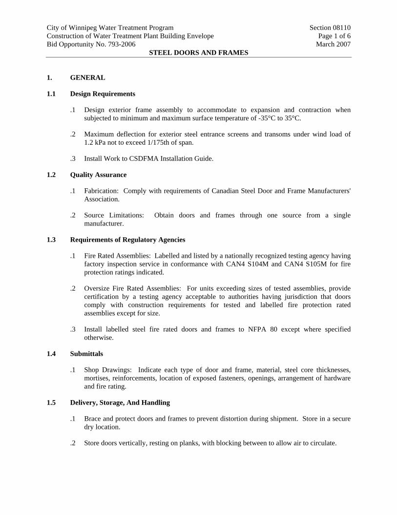
City of Winnipeg Water Treatment Program Section 08110 Construction of Water Treatment Plant Building Envelope Page 1 of 6 Bid Opportunity No. 793-2006 March 2007 STEEL DOORS AND FRAMES
1. GENERAL
1.1 Design Requirements
.1 Design exterior frame assembly to accommodate to expansion and contraction when subjected to minimum and maximum surface temperature of -35°C to 35°C.
.2 Maximum deflection for exterior steel entrance screens and transoms under wind load of 1.2 kPa not to exceed 1/175th of span.
.3 Install Work to CSDFMA Installation Guide.
1.2 Quality Assurance
.1 Fabrication: Comply with requirements of Canadian Steel Door and Frame Manufacturers' Association.
.2 Source Limitations: Obtain doors and frames through one source from a single manufacturer.
1.3 Requirements of Regulatory Agencies
.1 Fire Rated Assemblies: Labelled and listed by a nationally recognized testing agency having factory inspection service in conformance with CAN4 S104M and CAN4 S105M for fire protection ratings indicated.
.2 Oversize Fire Rated Assemblies: For units exceeding sizes of tested assemblies, provide certification by a testing agency acceptable to authorities having jurisdiction that doors comply with construction requirements for tested and labelled fire protection rated assemblies except for size.
.3 Install labelled steel fire rated doors and frames to NFPA 80 except where specified otherwise.
1.4 Submittals
.1 Shop Drawings: Indicate each type of door and frame, material, steel core thicknesses, mortises, reinforcements, location of exposed fasteners, openings, arrangement of hardware and fire rating.
1.5 Delivery, Storage, And Handling
.1 Brace and protect doors and frames to prevent distortion during shipment. Store in a secure dry location.
.2 Store doors vertically, resting on planks, with blocking between to allow air to circulate.
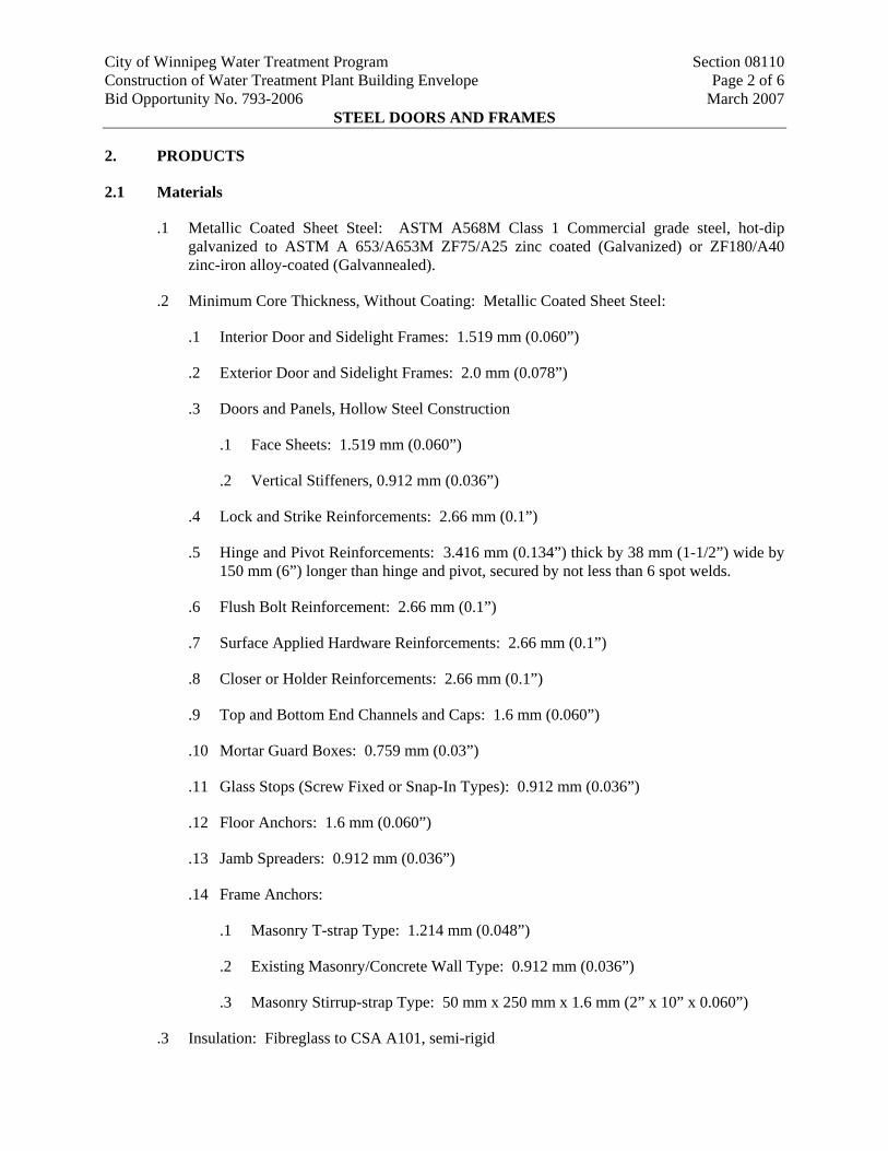
City of Winnipeg Water Treatment Program Section 08110 Construction of Water Treatment Plant Building Envelope Page 2 of 6 Bid Opportunity No. 793-2006 March 2007 STEEL DOORS AND FRAMES
2. PRODUCTS
2.1 Materials
.1 Metallic Coated Sheet Steel: ASTM A568M Class 1 Commercial grade steel, hot-dip galvanized to ASTM A 653/A653M ZF75/A25 zinc coated (Galvanized) or ZF180/A40 zinc-iron alloy-coated (Galvannealed).
.2 Minimum Core Thickness, Without Coating: Metallic Coated Sheet Steel:
.1 Interior Door and Sidelight Frames: 1.519 mm (0.060”)
.2 Exterior Door and Sidelight Frames: 2.0 mm (0.078”)
.3 Doors and Panels, Hollow Steel Construction
.1 Face Sheets: 1.519 mm (0.060”)
.2 Vertical Stiffeners, 0.912 mm (0.036”)
.4 Lock and Strike Reinforcements: 2.66 mm (0.1”)
.5 Hinge and Pivot Reinforcements: 3.416 mm (0.134”) thick by 38 mm (1-1/2”) wide by 150 mm (6”) longer than hinge and pivot, secured by not less than 6 spot welds.
.6 Flush Bolt Reinforcement: 2.66 mm (0.1”)
.7 Surface Applied Hardware Reinforcements: 2.66 mm (0.1”)
.8 Closer or Holder Reinforcements: 2.66 mm (0.1”)
.9 Top and Bottom End Channels and Caps: 1.6 mm (0.060”)
.10 Mortar Guard Boxes: 0.759 mm (0.03”)
.11 Glass Stops (Screw Fixed or Snap-In Types): 0.912 mm (0.036”)
.12 Floor Anchors: 1.6 mm (0.060”)
.13 Jamb Spreaders: 0.912 mm (0.036”)
.14 Frame Anchors:
.1 Masonry T-strap Type: 1.214 mm (0.048”)
.2 Existing Masonry/Concrete Wall Type: 0.912 mm (0.036”)
.3 Masonry Stirrup-strap Type: 50 mm x 250 mm x 1.6 mm (2” x 10” x 0.060”)
.3 Insulation: Fibreglass to CSA A101, semi-rigid

City of Winnipeg Water Treatment Program Section 08110 Construction of Water Treatment Plant Building Envelope Page 3 of 6 Bid Opportunity No. 793-2006 March 2007 STEEL DOORS AND FRAMES
.4 Adhesives for Steel Components: Heat resistant, spray grade, resin reinforced neoprene/rubber (polychloroprene) based, low viscosity, contact cement.
.5 Touch-up primer: CAN/CGSB-1.181, Zinc rich primer
.6 Door Silencers: single stud rubber/neoprene type
.1 Single Door: Three (3) silencers on strike jamb.
.2 Double Door: Two (2) silencers at head of each door leaf.
.7 Welding: CSA W59-M.
.8 Filler: Metallic paste, manufacturer's standard.
.9 Thermal Break: Rigid polyvinylchloride extrusion.
2.2 Fabrication - General
.1 Fabricate Work in accordance with CSDFMA specifications.
.2 Blank, reinforce, drill, and tap units for mortised, templated hardware, and electronic hardware using templates provided by the hardware suppliers. Reinforce units for surface mounted hardware.
.3 Do welding to CSA W59.
.4 Apply at factory; touch up primer to doors and frames manufactured from metallic coated steel where coating has been removed during fabrication.
.5 Make provisions in doors and frames to suit requirements of Section providing security devices.
.6 Fabricate fire rated assemblies to ULC requirements and bearing ULC, cUL or Warnock-Hersey International Ltd., label, as acceptable to authorities having jurisdiction.
.7 Locate fire rating labels on the inside of the frame hinge jamb and door hinge edge midway between the top hinge and the head of the door.
2.3 Fabrication – Frames and Screens
.1 Fabricate frames to profiles and maximum face sizes as required to suit design, welded construction.
.2 Cut mitres and joints accurately and weld continuously on inside of frame profile.
.3 Grind welded corners and joints to flat plane, fill with metallic paste filler and sand to uniform smooth finish.
.4 Protect mortised cutouts with mortar guard boxes in masonry and concrete constructions. Conceal fastenings except where exposed fastenings are required. Insulate exterior frame
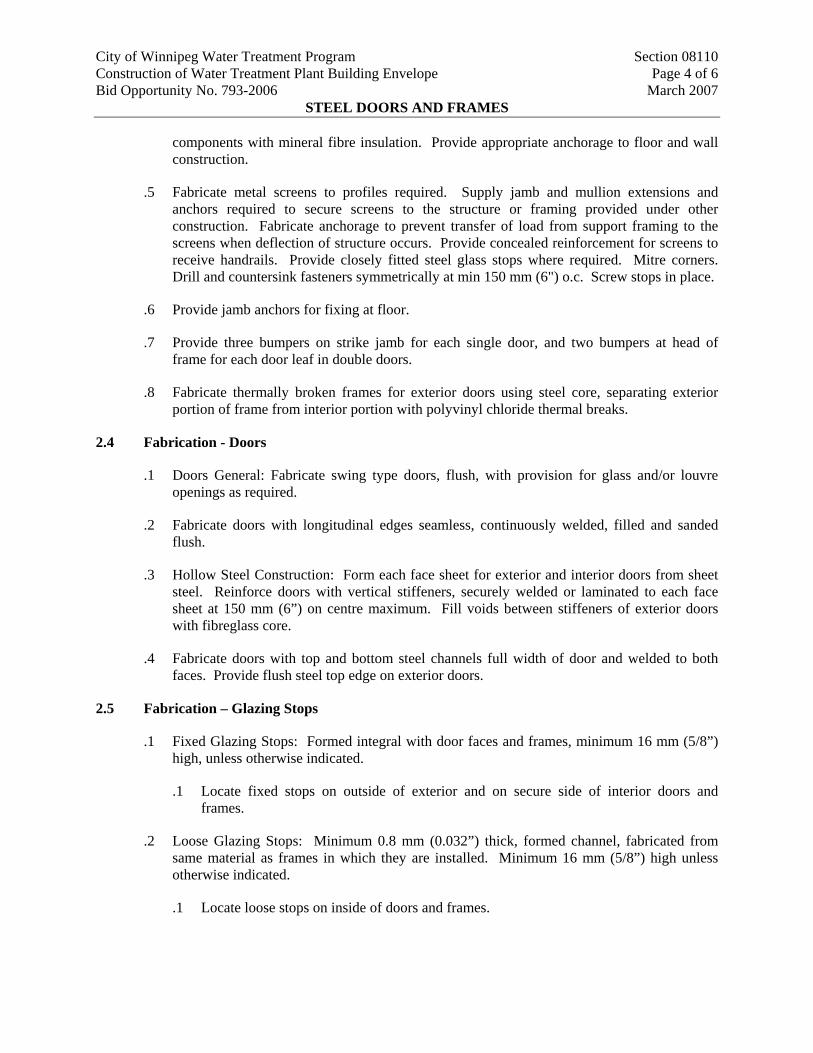
City of Winnipeg Water Treatment Program Section 08110 Construction of Water Treatment Plant Building Envelope Page 4 of 6 Bid Opportunity No. 793-2006 March 2007 STEEL DOORS AND FRAMES
components with mineral fibre insulation. Provide appropriate anchorage to floor and wall construction.
.5 Fabricate metal screens to profiles required. Supply jamb and mullion extensions and anchors required to secure screens to the structure or framing provided under other construction. Fabricate anchorage to prevent transfer of load from support framing to the screens when deflection of structure occurs. Provide concealed reinforcement for screens to receive handrails. Provide closely fitted steel glass stops where required. Mitre corners. Drill and countersink fasteners symmetrically at min 150 mm (6") o.c. Screw stops in place.
.6 Provide jamb anchors for fixing at floor.
.7 Provide three bumpers on strike jamb for each single door, and two bumpers at head of frame for each door leaf in double doors.
.8 Fabricate thermally broken frames for exterior doors using steel core, separating exterior portion of frame from interior portion with polyvinyl chloride thermal breaks.
2.4 Fabrication - Doors
.1 Doors General: Fabricate swing type doors, flush, with provision for glass and/or louvre openings as required.
.2 Fabricate doors with longitudinal edges seamless, continuously welded, filled and sanded flush.
.3 Hollow Steel Construction: Form each face sheet for exterior and interior doors from sheet steel. Reinforce doors with vertical stiffeners, securely welded or laminated to each face sheet at 150 mm (6”) on centre maximum. Fill voids between stiffeners of exterior doors with fibreglass core.
.4 Fabricate doors with top and bottom steel channels full width of door and welded to both faces. Provide flush steel top edge on exterior doors.
2.5 Fabrication – Glazing Stops
.1 Fixed Glazing Stops: Formed integral with door faces and frames, minimum 16 mm (5/8”) high, unless otherwise indicated.
.1 Locate fixed stops on outside of exterior and on secure side of interior doors and frames.
.2 Loose Glazing Stops: Minimum 0.8 mm (0.032”) thick, formed channel, fabricated from same material as frames in which they are installed. Minimum 16 mm (5/8”) high unless otherwise indicated.
.1 Locate loose stops on inside of doors and frames.
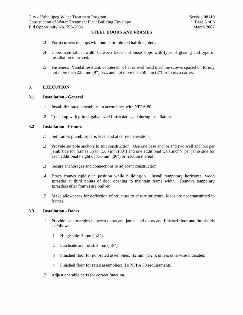
City of Winnipeg Water Treatment Program Section 08110 Construction of Water Treatment Plant Building Envelope Page 5 of 6 Bid Opportunity No. 793-2006 March 2007 STEEL DOORS AND FRAMES
.4 Coordinate rabbet width between fixed and loose stops with type of glazing and type of installation indicated.
.5 Fasteners: Vandal resistant, countersunk flat or oval head machine screws spaced uniformly m (9”) o.c., and not more than 50 mm (2”) from each corner.
3. EXECUTION
3.1 Installation - General
.1 Install fire rated assemblies in accordance with NFPA 80.
.2 Touch up with primer galvanized finish damaged during installation.
3.2 Inst
.1 Set frames plumb, square, level and at correct elevation.
.2 Provide suitable anchors to suit construction. Use one base anchor and two wall anchors per
.3 Secure anchorages and connections to adjacent construction.
.4 ames rigidly in position while building-in. Install temporary horizontal wood spreader at third points of door opening to maintain frame width. Remove temporary
ames are built-in.
3.3 Inst ti
.1 d jambs and doors and finished floor and thresholds as follows:
.1 Hinge side: 3 mm (1/8").
.2 Latchside and head: 3 mm (1/8").
.3 Finished floor for non-rated assemblies: 12 mm (1/2"), unless otherwise indicated.
.4 Finished floor for rated assemblies: To NFPA 80 requirements.
.2
.3 Form corners of stops with butted or mitered hairline joints.
not more than 225 m
allation - Frames
jamb side for frames up to 1500 mm (60") and one additional wall anchor per jamb side for each additional height of 750 mm (30") or fraction thereof.
Brace fr
spreaders after fr
.5 Make allowances for deflection of structure to ensure structural loads are not transmitted to frames.
alla on - Doors
Provide even margins between doors an
Adjust operable parts for correct function.
City of Winnipeg Water Treatment Program Section 08110 Construction of Water Treatment Plant Building Envelope Page 6 of 6 Bid Opportunity No. 793-2006 March 2007 STEEL DOORS AND FRAMES
3.4 Cleaning
.1 Clean and make good all surfaces soiled or otherwise damaged in connection with Work. Upon completion of Work and remove debris, equipment and excess material from Site.
END OF SECTION
City of Winnipeg Water Treatment Program Section 08335 Construction of Water Treatment Plant Building Envelope Page 1 of 4 Bid Opportunity No. 793-2006 March 2007
COILING DOORS
1. GENERAL
1.1 Submittals
.1 Shop Drawings: Indicate each type of coiling doors, arrangement of hardware, operating mechanism and required clearances.
.2 Maintenance Data: Supply operation and maintenance data for coiling doors for incorporation into Project Record Manual.
2. PRODUCTS
2.1 Materials
.1 Galvanized Steel Sheet: Commercial quality to ASTM A653, Z275 coating designation.
.2 Steel Shapes, Plates, and Similar Items: CAN/CSA-G40.20-G40.21-M, Grade 350W, hot dipped galvanized to CSA G164.
.3 Zinc Primer: Zinc rich, ready mix to CGSB 1-GP-181M.
.4 Insulation: Manufacturer's standard rigid cellular polystyrene or polyurethane-foam-type thermal insulation complying with maximum flame-spread and smoke-developed indexes of 75 and 450, respectively, in accordance with CAN/ULC S102.
.5 Weatherseals: Supply and install replaceable, adjustable, continuous, compressible weather-stripping gaskets of flexible vinyl, rubber, or neoprene fitted to jambs, bottom and top of exterior doors. At door head, use 3 mm (1/8”) thick, replaceable, continuous sheet secured to inside of hood.
.1 Motor Operated Doors: Combination bottom weatherseal and sensor edge.
2.2 Fabrication
.1 Fabricate rolling metal coiling doors to NFPA 80.
.2 Door Curtains: Fabricate overhead coiling door curtain of 22 mm interlocking galvanized sheet steel slats in baked finish, designed to withstand wind loading indicated, in a continuous length for width of door without splices. Unless otherwise indicated, Supply and Install slats of thickness and mechanical properties recommended by door manufacturer for performance, size, and type of door indicated. Supply and Install insulated doors as indicated.
.1 Insulated Doors: Fill slat cavity with thermal insulation, enclose insulation completely within metal slat faces.
City of Winnipeg Water Treatment Program Section 08335 Construction of Water Treatment Plant Building Envelope Page 2 of 4 Bid Opportunity No. 793-2006 March 2007
COILING DOORS
.3 Curtain Jamb Guides: Steel angles or channels and angles, with sufficient depth and strength to retain curtain, to allow curtain to operate smoothly, and to withstand loading. Build up units with not less than 5 mm (3/16”) thick galvanized steel. Slot bolt holes for guide adjustment.
.1 Supply and Install removable stops on guides to prevent overtravel of curtain, and a continuous bar for holding windlocks.
.4 Counterbalance: Construct counterbalance assembly consisting of torsion spring with 25% overload factor, and rated for 100,000 open-close cycles. Enclose spring in steel pipe to support door curtain and counterbalance mechanism with maximum deflection of 1/360th of opening width. Supply and Install ball bearings at rotating points. Supply and Install spring tension adjusting wheel, accessible for setting.
.1 Support counterbalance assembly on 5 mm minimum thickness steel plate brackets, forming end enclosures.
.5 Hood: Same material as doors, form to act as weatherseal and entirely enclose coiled curtain and operating mechanism at opening head. Contour to fit end brackets to which hood is attached. Roll and reinforce top and bottom edges for stiffness. Supply and Install closed ends for surface-mounted hoods and Supply and Install fascia for any portion of between jamb mounting projecting beyond wall face. Supply and Install intermediate support brackets as required to prevent sagging.
.1 Include automatic drop baffle to guard against passage of smoke or flame.
.6 Endlocks and Windlocks: Malleable-iron casings galvanized after fabrication, secured to curtain slats with galvanized rivets or high-strength nylon. Supply and Install locks on not less than alternate curtain slats for curtain alignment and resistance against lateral movement.
.7 Bottom Bars: Consisting of 2 angles, each not less than 38 mm x 38 mm x 3 mm (1 1/2” x 1 1/2” x 1/8”), galvanized, stainless-steel, or aluminium extrusions to suit type of curtain slats.
.8 Equip doors for locking from inside with cylinder locks compatible with masterkeyed cylinder.
2.3 Electric Door Operators
.1 General: Electric door operator assembly of size and capacity recommended and provided by door manufacturer, with electric motor and factory-prewired motor controls, starter, gear-reduction unit, solenoid-operated brake, clutch, remote-control stations, control devices, integral gearing for locking door, and accessories required for proper operation.
.2 Electric Motors: High starting torque, reversible, continuous-duty, worm gear, heavy duty industrial type, bracket mounted, Class A insulated, with overload protection; sized to start, accelerate, and operate door in either direction from any position, at not less than 0.2 m/s (2/ f/s
3) and not more than 0.3 m/s (1 f/s).
City of Winnipeg Water Treatment Program Section 08335 Construction of Water Treatment Plant Building Envelope Page 3 of 4 Bid Opportunity No. 793-2006 March 2007
COILING DOORS
.1 Coordinate wiring requirements and electrical characteristics of motors with building electrical system.
.3 Back Up Manual Operation: Chain hoist equipped with a disconnect device which allows the operator to be disengaged from the door and operate the door manually from the floor by hand in the event of a power failure without having to remove the drive roller chain.
.4 Brake: Solenoid disc brake to prevent door from coasting and secure stopping and locking of door in any position.
.5 Control Station: 3-button control, momentary contact type, open-close-stop, mounted on wall adjacent to door in location where directed by Contract Administrator.
.6 Sensor Edge: Supply and Install each motorized door with an automatic safety sensor edge, located within astragal or weather stripping mounted to bottom bar. Contact with sensor immediately stops and reverses downward door travel. Connect to control circuit using Manufacturer's standard take-up reel or self-coiling cable.
.1 Supply and Install pneumatically actuated automatic bottom bar.
.7 Limit Switches: Adjustable switches, interlocked with motor controls and set to automatically stop door at fully opened and fully closed positions.
2.4 Steel and Galvanized Steel Finishes
.1 Baked Finish: Manufacturer's standard baked finish consisting of primer and topcoat in accordance with coating manufacturer's written instructions for cleaning, pretreatment, application, thermosetting, and minimum dry film thickness. Colour to match Duranar XL UC55028XL Bright Silver Metallic by PPG.
3. EXECUTION
3.1 Electrical Co-Ordination
.1 The disconnect switch/junction box and power to the disconnect switch/junction box shall be supplied and installed under Electrical Divisions. Wiring and connection at and from the disconnect switch/junction box to motors, starters, switches, controls, safety devices and other items requiring power from the disconnect switch/junction box shall be the responsibility of this Section.
.2 Employ licensed electrician to wire and interconnect all operational and safety components for the Work. Terminate wiring required for connection to control circuitry and power in NEMA enclosures. Ground all control wiring.
.3 Do wiring in strict conformity with the Electrical Code and Electrical Divisions requirements.
City of Winnipeg Water Treatment Program Section 08335 Construction of Water Treatment Plant Building Envelope Page 4 of 4 Bid Opportunity No. 793-2006 March 2007
COILING DOORS
.4 Use CSA approved, tested and labelled materials and electrical components for intended use.
3.2 Installation
.1 Install work in accordance with Manufacturers' printed instructions.
.2 Adjust operable parts for correct function and smooth operation.
END OF SECTION
City of Winnipeg Water Treatment Program Section 08800 Construction of Water Treatment Plant Building Envelope Page 1 of 5 Bid Opportunity No. 793-2006 March 2007
GLASS AND GLAZING
1. GENERAL
1.1 General Requirements
.1 This Section includes glazing Work not specified in other Sections. Refer to other Sections for other glazing.
1.2 Submittals
.1 Provide samples of materials as requested. Label samples with manufacturer's name, with registered name of product, weight, and quality of glazing material.
.2 Provide maintenance data of glass and glazing system used in this Project including cleaning instructions for incorporation into manual.
1.3 Quality Assurance
.1 Perform Work in accordance with recommendations of Glazing Association of North America (GANA). Size glass to Code requirements and verify that openings for glazing are correctly sized and within tolerance.
.2 Glass Lites: Float, tempered, laminated or heat strengthened and in thicknesses in accordance with requirements of glass manufacturer as substantiated by the glass manufacturer's stress analysis for each location required, unless otherwise indicated.
.3 Design Conditions: Conforming to requirements of Division 8 Sections Curtain Wall and Entrances.
.4 Use a safety factor of 2.5:1 minimum for glass design.
1.4 Environmental Requirements
.1 Install glazing when ambient temperature is 10°C minimum. Maintain ventilated environment for 24 hours after application.
.2 Maintain minimum ambient temperature before, during and 24 hours after installation of glazing compounds.
1.5 Warranty
.1 Submit a 10 year warranty from Total Performance, against defects in the insulating glass units and warrant them to be free from material obstruction of vision as a result of dust or film formation on the internal glass surfaces by any cause, under design conditions, other than extrinsic glass breakage, but including breakage due to thermal shock and temperature differential due to inherent glass faults.
.1 The glass coatings will not discolour, oxidize, delaminate, or have scratches and pinholes and shall be uniform in thickness and uniform in colour throughout each glass unit and from glass unit to glass unit.

City of Winnipeg Water Treatment Program Section 08800 Construction of Water Treatment Plant Building Envelope Page 2 of 5 Bid Opportunity No. 793-2006 March 2007
GLASS AND GLAZING
.2 Insulating glass units will be free from condensation, fogging material obstruction of vision as a result of dust or film formation on the internal glass surfaces by any cause under normal conditions.
.3 The insulating glass units will not change their mechanical design properties and shall not in any way deteriorate, degrade, delaminate or change their visual appearance.
2. PRODUCTS
2.1 Materials
.1 Float Glass: CAN/CGSB-12.3, clear, glazing quality, minimum 6 mm (1/4") thick.
.2 Tempered Safety Glass: CAN/CGSB-12.1 Type 2, Class B, minimum 6 mm(1/4”) thick, heat treated using the horizontal tong free method, with roll-wave distortion parallel to bottom edge of glass as installed.
.3 Heat Strengthened Glass: ASTM C1048 Type HS, minimum 6 mm (1/4”) thick, heat treated using the horizontal tong free method, with roll-wave distortion parallel to bottom edge of glass as installed.
.4 Laminated Safety Glass: CAN/CGSB-12.1, Type 1, Class B, fabricated with minimum 1.6 mm clear polyvinylbutyral interlayer between 2 lites of minimum 3 mm (1/8”) thick glass, minimum overall 7.6 mm (5/16”) thick. Treat exposed edges of laminated glass susceptible to degradation by organic solvents and glazing compounds.
.5 Wired Glass: Clear, 6 mm (1/4") thick, polished Georgian 12 mm (1/2") square wire-reinforced, float glass, having the required fire resistance rating based on ULC testing.
.6 Tinted Glass: Heat absorbing glass, Solargray by PPG.
.7 Low Emissivity Coating: Solarban 60 by PPG.
.8 Ceramic Frit Coated Glass: Ceramic enamel applied by silk-screened process on No. 2 surface.
.9 Spandrel Glass: CAN2-12.9-M, minimum 6 mm (1/4") thickness or as indicated on Drawings, heat strengthened glass.
.10 Safety Scrim Backing: Self adhering polyester or polyethylene film 0.05 mm to 0.125 mm (2 mils to 5 mils) thick.
2.2 Accessories
.1 Glazing materials, primers and cleaning solvents: Mutually compatible, standard colours.
.2 Insulated Glass Unit Spacer Core: Extruded, thermoset polymer structural silicone foam tape with integrally incorporated desiccants, resistant to ozone, sunlight, oxidation, black, Super Spacer Premium Plus by Edgetech.
City of Winnipeg Water Treatment Program Section 08800 Construction of Water Treatment Plant Building Envelope Page 3 of 5 Bid Opportunity No. 793-2006 March 2007
GLASS AND GLAZING
.4 idizing polyisobutylene tape with continuous synthetic rubber spacer rod, sufficiently
wide and thick as to completely cover bite area of glazing unit when unit is pushed into
.5 ed, ribbon-shaped, non-drying, non-skinning, non-oxidizing, reinforced, polyisobutylene tape of sufficient width and thickness, 6 mm (1/4") minimum, to
.6 inus 5 respectively, neoprene rubber. Resistance to sunlight, weathering, oxidation and permanent
.7
trength, Durometer A hardness of 50, plus/minus 5, resistance to permanent set 30% maximum, minimum elongation at break of 300% and resistance to ozone showing no
.8 Safety Decals: 50 mm (2") diameter round, self-adhesive, pressure-sensitive, black, g, decals with clear, colourless, non-yellowing adhesive.
2.3
.1 ion of North America. Cut glass clean and free of nicks and damaged edges. Grind smooth and
t cut or abrade tempered, heat treated, or coated glass.
2.4
.1
position. Edges of glass shall be straight cut, free of nicks and other imperfections conducive to
.1 t Contractor’s option, dual seal with polyisobutylene primary and polysulfide secondary sealants, or dual seal with polyisobutylene primary and silicone
.2 plus or minus 2 mm (0.080”) and the primary seal not extend past the inside edge of
spacer core by more than 1.6 mm (0.060”). Weld or vulcanize spacer core corners and
2.5
.1 Exterior Vision Units: Double glazed Insulating glass units, tinted glass outer lite, clear glass inner lite with low emissivity coating on No. 3 surface.
.3 Glazing Compound: CAN2-19.13, one component silicone base.
Glazing Tape, Preshimed: Extruded, ribbon shaped, non-drying, non-skinning, non-ox
place.
Glazing Tape: Extrud
permit a continuous seal.
Shims, Spacers and Setting Blocks: 45, 50 and 90 Durometer A hardness plus/m
deformation under load shall be prime essentials of shims, spacers and setting blocks.
Glazing Gaskets: Neoprene, EPDM, thermoplastic or other approved material, of sufficient thickness to be 25% compressed when installed. Gaskets shall have a 13.8 MPa (2000 psi) tensile s
cracks.
non-facin
Fabrication
Accurately size glass to fit openings allowing clearances recommended by Glass Associat
polish exposed glass edges. Do no
Fabrication – Insulating Glass Units
Insulating glass units: CAN2-12.8, double and triple glazed, composed of lites of minimum 6 mm thick glass separated by a 13 mm wide dehydrated air space, double sealed and atmospheric pressure equalized to prevent bowing of the glass lites in the vertical
breakage. Coatings used in structural glazing shall be edge deleted 10 mm.
Sealing System: A
secondary sealants.
Set spacer core straight and even into glass units with a maximum variation in line of spacer core of
joints.
Glass And Glazing Types
City of Winnipeg Water Treatment Program Section 08800 Construction of Water Treatment Plant Building Envelope Page 4 of 5 Bid Opportunity No. 793-2006 March 2007
GLASS AND GLAZING
.2 Exterior Spandrel Glass: Single glazed clear glass, ceramic frit coating and scrim backing on No.2 surface.
3. EXECUTION
3.1 Inspection
.1 Verify dimensions at the Site before proceeding with fabrication or glazing units.
.2 Ensure that openings are free from distortion, and that surfaces are free from protrusions that will obstruct face and edge clearances.
.3 Ensure that ferrous metals are painted or zinc coated; and that surfaces are suitable for adhesion of the glazing materials.
.4 Ensure that operable units to be glazed are adjusted for proper operation.
.5 Ensure that ambient and surface temperatures are above 5°C.
3.2 Preparation
.1 Free rabbets, stops and glass edges of dust, dirt, moisture, oil and other foreign matter detrimental to or obstructing the glazing material.
3.3 Installation - General
.1 Handle and install glass in accordance with manufacturer's directions. Prevent nicks, abrasions and other damage likely to develop stress on edges.
.2 Without limitations, cracked or scratched glass, shrinking, cracking, staining, hardening, sagging of glazing materials; loosening or rattling of glass; leaking of glazed joints will be rejected.
.3 Remove and replace glazing stops in original locations, using original fasteners, securely set and undamaged.
.4 Use setting blocks and spacers as required to properly support the glass, centred in place in the glazing space independent of the materials and to uniformly distribute its load.
.5 Use a minimum of 2 setting blocks, located at the quarter points. Locate spacers at jamb edges of glass, uniformly spaced at 600 mm (24") o.c. maximum, and 300 mm (12") maximum from top and bottom.
.6 Assess coloured glass units for colour uniformity and arrange to avoid abrupt variation in appearance.
.7 Set glass properly centred with uniform bite and face and edge clearance, free from twist, warp or other distortion likely to develop stress.
City of Winnipeg Water Treatment Program Section 08800 Construction of Water Treatment Plant Building Envelope Page 5 of 5 Bid Opportunity No. 793-2006 March 2007
GLASS AND GLAZING
.8 Leave labels on glass until it has been set and inspected and approved. Leave glass whole and without cracks, scratches or other defects and with setting in perfect condition at completion, to the approval of the Contract Administrator.
.9 Remove rejected, broken or damaged glass due to defective materials or improper setting and replace with perfect materials. Units producing distorted vision will be rejected and replaced at the reasonable discretion of the Contract Administrator.
3.4 Cleaning
.1 Clean and make good to the approval of the Contract Administrator, surfaces soiled or otherwise damaged in connection with the Work of this Section. Pay the cost of replacing finishes or materials that cannot be satisfactorily cleaned.
.2 Upon completion of the Work, remove all debris, equipment and excess material resulting from the Work of this Section from the Site.
END OF SECTION
City of Winnipeg Water Treatment Program Section 08900 Construction of Water Treatment Plant Building Envelope Page 1 of 10 Bid Opportunity No. 793-2006 March 2007
ALUMINIUM CURTAIN WALL AND ENTRANCES
1. GENERAL
1.1 System Description
.1 Wind Loads: Design and install curtain wall system to withstand positive and negative wind and service pressure loads normal to wall plane, to requirements of the building code.
.2 Thermal Movement: Provide for thermal movement caused by design temperatures required by the building code and a 82°C surface temperature, without causing buckling stresses on glass, joint seal failure, undue stress on structural elements, damaging loads on fasteners, reduction of performance, or detrimental effects.
.3 Curtain Wall System Performance Criteria: Comply with the following performance requirements, demonstrated by testing manufacturer's assemblies in accordance with test methods indicated.
.1 Elastic Deflection Limits of Vertical Mullions: Tested in accordance with ASTM E330. Deflection limits shall be such that the integrity of the glass and air seals are maintained at design loading. Permanent deformation of members due to applied loads are not permitted. Deflection limitation shall be lesser of the following:
.1 L/175 of clear span for spans up to 4.1 m; L/240 of clear spans plus 6 mm for spans greater than 4.1 m.
.2 An amount that restricts edge deflection of individual glazing lites to 19 mm.
.2 Elastic Deflection Limit of Horizontal Mullions: Limited to amount not exceeding that which reduces glazing bite to less than 75% of design dimension and which reduces edge clearance between framing members and glazing or other fixed components to less than 3 mm, as tested to ASTM E330.
.3 Air Infiltration/Exfiltration: Tested in accordance with ASTM E283, maximum 0.3 L/s/m2 (0.06 cfm/ft2) at a static air pressure differential of 300 Pa (6.24 psf).
.4 Water Infiltration: No uncontrolled water on indoor face of any component when tested in accordance with ASTM E331 at test pressure differential of 380 Pa (8 psf).
.4 Entrance System Performance Criteria: Comply with the following performance requirements, demonstrated by testing manufacturer's assemblies in accordance with test methods indicated.
.1 Air Infiltration/Exfiltration: Tested in accordance with ASTM E 283, at a static air pressure differential of 75 Pa (1.57 psf), based on door leaf module of 900 x 2100 mm (36” x 84”).
.1 Single Door and Frame: Maximum 2.83 m3/h/m (0.50 cfm/ft.) of perimeter crack.
.2 Pair of Doors and Frame: Maximum 5.66 m3/h/m (1.0 cfm/ft.) of perimeter crack.

City of Winnipeg Water Treatment Program Section 08900 Construction of Water Treatment Plant Building Envelope Page 2 of 10 Bid Opportunity No. 793-2006 March 2007
ALUMINIUM CURTAIN WALL AND ENTRANCES
.2 Structural: Door corner structural strength test using a dual moment loading criteria, minimum 132 kg (290 kg).
.3 Forced Entry Resistance: Tests performed simultaneously with 136 kg (300 lbs) forces applied to the active door panel within 75 mm (3”) of the locks in the direction that opens the door and 68 kg (150 lbs) forces applied in both perpendicular directions to the 136 kg (300 lbs) force simultaneously.
1.2 Quality Control
.1 Installer: Trained and approved by the manufacturer and having a minimum three years experience in the installation of the work described in this Section and can show evidence of satisfactory completion of projects of similar size, scope and type. If requested, provide letter of certification from Manufacturer stating that installer is certified applicator of its products, and is familiar with proper procedures and installation requirements required by the Manufacturer.
.2 Maintenance Seminars: Provide, to the City, training seminars and recommendations on product maintenance procedures.
.3 Pre-Installation Meeting: Two (2) weeks prior to commencing work of this Section, arrange for Manufacturer's technical representative to visit the site and review preparatory and installation procedures to be followed, conditions under which the work will be done, and inspect the surfaces to receive the work of this Section. Advise the Contract Administrator of the date and time of the meeting.
.4 Manufacturer’s Site Inspection: Have the Manufacturer’s technical representative inspect the Work at suitable intervals during application and at conclusion of the work of this Section, to ensure the Work is correctly installed. When requested, submit manufacturer’s inspection reports and verification that the work of this Section is correctly installed.
1.3 Submittals
.1 Shop Drawings: Submit Shop drawings in accordance with 01300, bearing the seal and signature of a Professional Engineer registered in the Province of Manitoba. Include plans, elevations, sections, details, hardware, attachments to other work, and the following:
.1 Mullion details, including reinforcement and stiffeners.
.2 Joinery details.
.3 Expansion provisions.
.4 Flashing and drainage details.
.5 Thermal-break details.
.6 Glazing details.
.7 Cleaning provisions.
City of Winnipeg Water Treatment Program Section 08900 Construction of Water Treatment Plant Building Envelope Page 3 of 10 Bid Opportunity No. 793-2006 March 2007
ALUMINIUM CURTAIN WALL AND ENTRANCES
.2 Structural Analysis Report: Bearing signature and seal of Professional Engineer registered in the Province of Manitoba responsible for its preparation and used to determine the following:
.1 Structural test pressures and design pressures from basic wind speeds.
.2 Deflection limitations of glass framing systems.
.3 Samples: Submit sample sections of component parts of curtain wall system including frame, sash, sill, glazing, and waterproofing method.
.4 Product Test Reports: Submit report from an independent testing laboratory, indicating products meet or exceed performance requirements.
.1 Base report on evaluation of comprehensive tests performed within the last four (4) years by a qualified testing agency, for each type, grade, and size of aluminium curtain wall system. Test results based on use of down-sized test units will not be accepted.
.5 Maintenance Data and Operating Instructions: On completion of work, supply three (3) copies of maintenance and glazing instructions for insertion in maintenance manual.
1.4 Delivery, Storage, and Handling
.1 Store in a dry, protected area on Site, in original undamaged containers with Manufacturer's labels and seals intact.
.2 Factory apply strippable coating or protective wrappings on exposed surfaces of aluminium. Do not remove protection until completion of building.
1.5 Warranties
.1 Warrant the work of this Section in accordance with the requirements of the Contract Documents.
.2 Warrant the following:
.1 The curtain walls will be structurally sound and free from distortion, deflection, misalignment and will be weathertight.
.2 The metals will not warp, buckle, oil can, distort and their finishes will not crack, peel, rust, pit, or otherwise corrode, discolour or fade.
.3 The gaskets, tapes and sealants will be free from deterioration or dislocation from sunlight, weather or oxidation. The gasketing shall be free from permanent deformation under load.
.4 The air/vapour barrier will be continuous with the building air/vapour barriers.

City of Winnipeg Water Treatment Program Section 08900 Construction of Water Treatment Plant Building Envelope Page 4 of 10 Bid Opportunity No. 793-2006 March 2007
ALUMINIUM CURTAIN WALL AND ENTRANCES
2. PRODUCTS
2.1 Manufacturers
.1 Specified Products: The design for the work of this Section is based on the products named. Products by other manufacturers similar in function, design, performance, and construction complying with requirements of this Section may be incorporated into the Work subject to Contract Administrator’s acceptance.
.1 Curtain Wall Framing: Thermally broken, 1600 Series by Kawneer or 2500 Series by Alumicor.
.2 Entrance Doors: Thermally broken, 360 Insulclad by Kawneer or 400A Insuldor by Alumicor.
.3 Vestibule Framing: Non-thermally broken, Trifab 450 Series by Kawneer or 800 Series by Alumicor..
2.2 Materials
.1 Aluminium Association Alloy AA6063-T5 for extruded shapes, commercial quality AA1100-H14 aluminium sheet for formed shapes.
.2 Steel: CAN3-G40.21-M Grade 300W.
.3 Flashing: Aluminium, finished to match framing, minimum 24 gauge.
.4 Bolts, Screws, Anchors and Fasteners: Stainless steel or aluminium for aluminium connections; cadmium plated steel may be used at interior side of air barriers; galvanized steel elsewhere.
.5 Slip washers: Teflon coated steel or aluminium washers.
.6 Loose Insulation: Glass fibre or mineral wool, CSA A101-M, Type I, Loose, light density insulation.
.7 Foam Insulation: Enerfoam by Dow Chemical.
.8 Temporary Strips and Safety Markings: Supply 25 mm (1") wide, light reflecting, easily removable, pressure sensitive tape applied over glass lites in windows. Windows shall have corner to corner cross stripes from aluminium frames.
.9 Rust Inhibiting Primer: CAN/CGSB-1.40-M.
.10 Isolation Coating: CAN/CGSB-1.108-M, acid and alkali resistant.
2.3 Metal Air/Vapour Barriers (Spandrel Back Pans)
.1 Sheet Metal: Minimum 20 gauge sheet steel, galvanized, complying with ASTM A653/653M, zinc coating Z275.
City of Winnipeg Water Treatment Program Section 08900 Construction of Water Treatment Plant Building Envelope Page 5 of 10 Bid Opportunity No. 793-2006 March 2007
ALUMINIUM CURTAIN WALL AND ENTRANCES
.2 Spandrel Insulation: Mineral fibre board insulation, CavityRock by Roxul or CW50 by Fibrex, complete with compatible fire retardant insulation adhesive.
.3 Stick Clips: 25 mm (1") diameter perforated disc base with integral [3 mm|1/8"] square sharpened pin of moulded polyvinylchloride in lengths to suit insulation thickness.
.1 Insulation Retainers: 25 x 25 mm (1" x 1") galvanized sheet steel, punched to catch on pins.
.2 Adhesive for apply clips: High-strength, resilient adhesive having a drying time of 0 to 30 minutes (rapid initial set), and 24 hours final set. Adhesive shall be compatible with the specified insulation adhesive, insulation and galvanized steel.
.4 Gun Welded Pins: Alternative at the Contractor's option to stick clips, 3 mm (1/ ")8 diameter galvanized steel pins with cup heads, of length to suit insulation thickness and suitable for gun shot welding to the back pans.
.5 Stiffeners: Hot or cold rolled steel or galvanized sheet steel sections, to the requirements of this Section.
2.4 Sealants
.1 Joint Primer, Surface Conditioners and Cleaning Agents: As recommended by respective glazing and sealant compound manufacturer.
.2 Joint Backing Material: Polyethylene foam rope, closed cell type, out-sized minimum 50% larger than joint width and compatible with joint sealant.
.3 Sealant: Non-bleeding, non-migrating, non-sagging, capable of supporting their own weight, standard colour.
.1 Sealant between aluminium framing and adjacent structures: CAN/CGSB-19.24-M, Type 2, Class B, multi-component, urethane based.
.2 Sealant in concealed-sealing of thin joints in metal work: Non-hardening, polyisobutylene or partially vulcanized rubber base.
2.5 Fabrication – Curtain Wall and Window Frames
.1 Form work true to detail, free from defects impairing appearance, strength and durability.
.2 Fabricate aluminium frames with an integral, concealed, low-conductance thermal barrier; located between exterior materials and members exposed on interior side; in a manner that eliminates direct metal-to-metal contact.
.3 Apply sealant to joints within units and components, including junction of frames to provide air/vapour and watertight joints. Do such sealant application in a concealed manner.
.4 Provide punched louvres or holes through exterior glazing flange for venting and drainage.
.5 Design mullions and framing members to accommodate glazing units.
City of Winnipeg Water Treatment Program Section 08900 Construction of Water Treatment Plant Building Envelope Page 6 of 10 Bid Opportunity No. 793-2006 March 2007
ALUMINIUM CURTAIN WALL AND ENTRANCES
.6 Design, fabricate and install brackets and anchorage devices attached to warm side of thermal break. Make allowance for unevenness and dimensional difference in structure, expansion and contraction of framing members without creating undesirable stresses in components to adequately sustain curtain wall system, movements in structure, and superimposed wind and rain loads.
.7 Reinforce and prepare curtain wall frames for related hardware where applicable.
.8 Fabricate system with drained glazing cavity between sealed unit and frame into which it is secured to drain out of curtain wall system to exterior.
.9 Form continuous sills, stools and flashings with intermediate clips, anchor devices and reinforcement in shop and as far as practical assemble units in shop. Supply filler and closure pieces as required. Fill corners and other open areas within construction with loose insulation.
.10 Ensure corners of formed work are mitred and closely fitted. Apply back-up sealants designed for this purpose, on inside of joints in aluminium work by this trade. Provide drainage towards exterior at bottom of glazing rebates.
.11 Deburr and make smooth sharp milled edges and corners of sash frames.
.12 Construct and erect work free of exposed fasteners. If unavoidable, ensure fasteners are tamper proof.
.13 Factory glaze and weatherstrip entrances as far as practicable. Secure weatherstripping properly to prevent shrinkage or movement. Ensure it is easily replaceable without use of special tools and is resistant to deterioration by weathering or aging.
.14 Apply two (2) shop coats of rust inhibiting primer to steel components. Take other necessary measures to prevent future deterioration due to corrosion and electrolysis during fabrication.
.15 Welding of component members is permitted providing it does not in any way mar surface appearance. Carry out welding with argon shielded electric arcs to ensure complete fusion of metal. Make joints tight, in true plane, ground and sand smooth, flush with base metal. Do welding on concealed surface.
2.6 Fabrication –Metal Air/Vapour Barriers
.1 Brake-form sheet metal air/vapour barriers to permit assembly using self-tapping screws, and attachment using power activated or pneumatic fixings or other means of secure fastening.
.2 Make provision in barrier design to accommodate movement resulting from thermal changes and from structural deflections.
.3 Cut, fit and form metal air/vapour barriers as required to accommodate framing, anchors, connections, mechanical, and electrical appurtenances and other obstructions.
City of Winnipeg Water Treatment Program Section 08900 Construction of Water Treatment Plant Building Envelope Page 7 of 10 Bid Opportunity No. 793-2006 March 2007
ALUMINIUM CURTAIN WALL AND ENTRANCES
2.7 Fabrication - Entrance System
.1 Preparation for Hardware: Drill and cut to template for hardware. Reinforce frames and door stiles to receive hardware in accordance with Manufacturer's Recommendations.
.2 Arrange fasteners and attachments to conceal from view.
.3 Accurately fit and secure joints and corners. Make joints hairline in appearance.
.4 Prepare components with internal reinforcement for door hardware.
.5 Door Frame
.1 Fabricate and assemble units with joints only at intersection of aluminum members with uniform hairline joints; rigidly secure, and sealed in accordance with Manufacturer's Recommendations.
.6 Doors
.1 Corner Construction: Mechanical clip fastening, sigma deep penetration plug welds and 30 mm (1 1/8") long fillet welds inside and outside of all four corners
.2 Glazing Stops: Manufacturer's standard snap-in glazing stops with EPDM glazing gaskets. Factory glaze doors.
.7 Door Hardware
.1 Hinges: Stainless steel, continuous hinges.
.2 Closers: Overhead concealed, barrier free, heavy duty, complete with integral stop arms or overhead door stops.
.3 Locks: Thumb piece on inside, high security deadbolt.
.4 Flushbolts, Pairs of Doors: Manual top and bottom concealed flush bolts.
.5 Push/Pulls: Full height and width of doors, round bar type, finish to match entrances.
.6 Weatherstripping: Manufacturer's standard pile type in replaceable rabbets for stiles; Manufacturer's standard EPDM bulb type in door frames.
.7 Thresholds: Barrier free, Mill finish aluminum threshold with elastomer weather-strip and counterflashed.
2.8 Fabrication - Aluminium Trim
.1 Fabricate work and support members in a manner which will provide an installation free of exposed fastenings, with sufficient support and allowance for thermal movement.
.2 Fabricate trim, sills, corner pieces and filler pieces of 3 mm (1/8") thick plate aluminium to profiles shown, by welding prior to application of finish. Make all planes flat, free of visible
City of Winnipeg Water Treatment Program Section 08900 Construction of Water Treatment Plant Building Envelope Page 8 of 10 Bid Opportunity No. 793-2006 March 2007
ALUMINIUM CURTAIN WALL AND ENTRANCES
distortion and with edges straight and true, corners square and bend of minimum radius. Provide concealed clips for fastening plate assemblies in place.
.3 Reinforce work as required to prevent warpage, oil canning, buckling effect and to meet design requirements. Weld marks shall not telegraph to the finished side.
.4 Provide inconspicuous weep holes to properly drain to exterior.
.5 Aluminium Sills: Extrude to size and shape as detailed, complete with end drip deflectors, expansion cover plates and necessary anchors.
2.9 Aluminium Finishes
.1 Prefinish exposed to view aluminium surfaces in high performance fluoropolymer metallic finish. Ensure aluminium finish is free from blemishes or scratches and uniform in colour and sheen. Pretreat aluminium and apply primer and finish coats in accordance with manufacturer's instructions.
.1 High performance fluoropolymer metallic finish: AA-C12C40R1x, chemical finish: cleaned with inhibited chemicals; chemical finish: conversion coatings; organic coating: Manufacturer's standard three coat, thermocured system consisting of specially formulated inhibitive primer, fluoropolymer color coat, and clear fluoropolymer topcoat, with both color coat and clear topcoat containing not less than 70% polyvinylidene fluoride resin by weight. Prepare, pretreat, and apply coating to exposed metal surfaces to comply with AAMA 2605 and with coating and resin Manufacturers' written instructions.
.1 Colour 1: Duranar XL UC51131XL Bright Silver Metallic by PPG.
.2 Colour 2: Duranar XL UC52061XL Concord Blue Metallic by PPG.
3. EXECUTION
3.1 Installation - General
.1 Apply isolation coating of approximately 0.76 mm (30 mil) dry film thickness, or other suitable permanent separator on concealed contact surfaces of dissimilar materials, before assembly or installation where there is possibility of corrosive or electrolytic action with concrete, masonry, mortar, or steel.
.2 Set work in its correct location, level, square and plumb and at proper elevations, with nominal face of framing aligned in a single vertical plane. Fasten and anchor framing in place. Install in accordance with manufacturer's instructions and reviewed shop drawings.
.3 Anchor component parts securely in place as indicated, by bolting or other permanent mechanical attachment system, which will comply with performance requirements and permit movement as intended or necessary.

City of Winnipeg Water Treatment Program Section 08900 Construction of Water Treatment Plant Building Envelope Page 9 of 10 Bid Opportunity No. 793-2006 March 2007
ALUMINIUM CURTAIN WALL AND ENTRANCES
surfaces disturbed by field welding or other operations.
.5 Leave final installation water, air and weather tight.
.6 Set thresholds in bed of mastic and secure.
.7 Apply foam insulation where detailed.
3.2 Inst
.1 sulation clips at 300 mm (12") o.c. both ways. Support clips in place until adhesive has set unless welded clips are used.
entir
utt joints.
ing clips. Butt insulation boards tightly. Install retainers to clips.
.3 Isolate metal air/vapour barriers with thermal breaks and spacers as indicated.
3.3 Installation - Sealant
.1
.2 indows, sills, and other components in this Section and adjacent construction both inside and outside to provide weather tight seal on exterior and
age.
ance with manufacturer's instructions.
.4 cordance with manufacturer's instructions.
nt pressure to fill voids and joints solid.
.6 Form surfaces smooth, free from ridges, wrinkles, sags, air pockets, embedded impurities.
.7 Tool exposed surfaces to slightly concave shape.
.8 Remove excess compound promptly as work progresses and upon completion.
.9 Glaz
avity.
.4 Clean and restore primer and bituminous paint to
allation – Air And Vapour Barrier
Metal Spandrel Back Pans (Air/Vapour Barrier): Adhere in
Avoid burn through when welding clips. Notched trowel apply insulation adhesive over e surface of barrier and around clips held with adhesive.
.1 Apply insulation to the cold-in-winter side of the metal air/vapour barriers erected. Cut insulation slightly over-size as required to ensure tight b
.2 Press insulation boards firmly to barrier impaling them on clips without bend
Prepare and seal joints to provide weathertight seal.
Apply sealant to joints between w
air/vapour seal on interior. Provide toe bead and/or heal bead of sealant around perimeter or sealed unit to prevent air leak
.3 Apply joint backing to achieve correct joint depth and shape in accord
Mix, apply and cure sealant in strict ac
.5 Apply sealant in continuous full beads, using gun with proper size nozzle and sufficie
ing:
.1 Provide heel bead at bottom of interior edge of sealed units and up lower 75 mm (3") of each vertical to provide a vented glazing c
City of Winnipeg Water Treatment Program Section 08900 Construction of Water Treatment Plant Building Envelope Page 10 of 10 Bid Opportunity No. 793-2006 March 2007
ALUMINIUM CURTAIN WALL AND ENTRANCES
l glazing compound at an angle sloping away from glass. Remove excess glazing compound from stops and glass.
3.4 Adju
.1 roughout construction period, without deterioration or damage at time of acceptance. Select methods of cleaning which will promote achievement
r materials that weather or age with exposure. Do not use abrasives.
.2
.3 is handed over to City, make good damage and disfigurement. Remove protective covering and coating from aluminium
.4 Immediately before Substantial Performance, clean work thoroughly, inside and out. Demonstrate proper cleaning final cleaning.
END OF SECTION
.2 Neatly too
st and Clean
Maintain work in a clean condition th
of uniform appearance and stabilized colours and textures fo
Adjust operating devices and leave in perfect working order.
Immediately prior to cleaning of glass and before building
surfaces, inside and out, and clean surfaces, remove labels, stripes and protective devices and polish glass surfaces, immediately prior to final acceptance.
methods to City during