Embed Size (px)
Citation preview

QUALIFICATIONS:• UL 555 & CAN/ULC-S112 CLASSIFIED DYNAMIC FIRE DAMPER.
1 1/2 hr. label (File # R9492).
• Meets all the requirements of UL and NFPA 80, 90A and 101 for fire dampers in dynamic HVAC systems, as well as IBC and NBC (Canada) Building Code requirements.
• City of New York Board of Standards and Appeals. Cal. No. 460-88-SA.
• California State Fire Marshal: Fire Damper Listing No. 3225-0935:0113.
• Maximum velocity: 4000 fpm @ 4" w.g. (20 m/s @ 1 kPa).
SCHEDULE TYPE:
PROJECT:
ENGINEER:CONTRACTOR:
DATE B SERIES SUPERSEDES DRAWING NO.
11 - 6 - 14 FD 4 - 28 - 14 D0100-7
DYNAMIC OUT OF WALL CURTAIN TYPE FIRE DAMPER FOR GRILLES AND REGISTERSFOR DYNAMIC OR STATIC SYSTEMSMODEL: D0110GOW (TYPE A)
Nailor Industries Inc. reserves the right to change any information concerning product or pricing without notice.
For installation instructions, see IOM-FDGOWINST.Dimensions are in inches (mm).
Model D0110GOW is an "out of wall or floor" integral sleeve dynamiccurtain type fire damper, specifically designed for supply or return ductsthat terminate at a grille or register. For use where local building codesrequire the protection of HVAC ductwork penetrations in walls, partitionsor floors that have a fire resistance rating of up to two hours.
The D0110GOW design provides sufficient damper off-set toaccommodate most commercial grille/register designs while ensuring anapproved installation in any fire partition or wall no matter how narrow.This model is particularly suited for use in common steel stud drywallpartition designs, as narrow as 3 1/2" (89) where a traditional "within theplane of the wall" fire damper installation is not possible.
FEATURES:• 3/4" (19) mounting flange simplifies installation, is hidden by grille frame
and eliminates the requirement for unsightly mounting angles.
• Qualified for use with steel or alum. grilles and registers (by Nailor or others).
• Shipped complete with integral insulated sleeve. No field assembly required.
• Suitable for partition/wall thicknesses up to 8" (203) (see notes).
• Can be installed completely from grille side of wall.
Rear retaining angles are not required.
• UL Classified for vertical or horizontal installation.
• Qualified for use in both Dynamic and Static Systems.
STANDARD CONSTRUCTION:Frame: One piece, 22 ga. (0.85) roll-formed galvanized steel.Blades: Curtain type interlocking blades, 22 ga. (0.85) roll-formed
galvanized steel.Fusible Link: 165°F (74°C) standard. UL Listed. 212°F (100°C) available. Sleeve: 10" (254) x 16 ga. (1.61) galvanized steel with 3/4" (19)
wide mounting flange.Blade Closure: Stainless steel closure springs & galv. steel locking ramps. Insulation: Intumescent thermal insulation on four sides.
Sizes (Duct W x H):
¨ Individual sections of multiple section assembly not to exceed 24" (610) in width, up to 48" (1219) wide. Assemblies larger than 48" (1219) in width will be made up of individualsections not to exceed 18" (457) wide.
STANDARD DAMPER/SLEEVE:
NOTE:1. Dependent upon partition/wall thickness and thedamper off-set clearance requirement for desiredgrille/register, a standard "within the wall" firedamper with no sleeve insulation may be acceptable.Refer to Nailor Model Series 0100G and 0200G forstatic systems or D0100G for dynamic systems.
DYNAMIC VELOCITY/PRESSURE RATING:q 24 2000 fpm @ 4" w.g. (Standard)q 34 3000 fpm @ 4" w.g.q 44 4000 fpm @ 4" w.g.
(Optional)
1 3/4"(44)
4 1/4"(108)
10" (254)
4"(102)
H
}
W
H3/4" (19)FLANGE
FIRE DAMPER
GRILLE / REGISTER
THERMALINSULATION
Velocity/Pressure
Rating
Single Section Multiple Section
Minimum Maximum Maximum
Vertical Horizontal Vertical Horizontal Vertical Horizontal
24 6" x 6"(152 x 152)
6" x 6"(152 x 152)
24" x 24"(610 x 610)
24" x 24"(610 x 610)
¨ 36" x 24"(914 x 610)
—
34, 44 6" x 6"(152 x 152) — 24" x 24"
(610 x 610) — — —
SCHEDULE TYPE:
PROJECT:
ENGINEER:CONTRACTOR:
DATE B SERIES SUPERSEDES DRAWING NO.
31 - 7 - 00R ACC 1 - 98R/0100-6 ACC.ETL
CURTAIN FIRE DAMPER ACCESSORYELECTRO-THERMAL LINKMODEL: ETL
Nailor Industries Inc. reserves the right to change any information concerning product or pricing without notice.
Nailor Industries Inc.
Dimensions are in inches (mm).
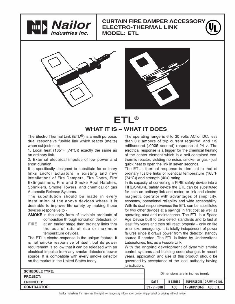
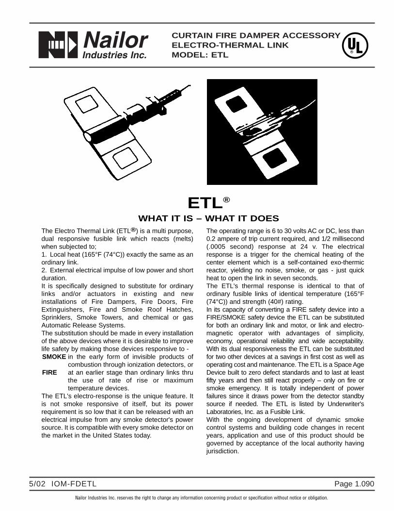
The Electro Thermal Link (ETL®) is a multi purpose,dual responsive fusible link which reacts (melts)when subjected to;1. Local heat (165°F (74°C)) exactly the same asan ordinary link.2. External electrical impulse of low power andshort duration.It is specifically designed to substitute for ordinarylinks and/or actuators in existing and newinstallations of Fire Dampers, Fire Doors, FireExtinguishers, Fire and Smoke Roof Hatches,Sprinklers, Smoke Towers, and chemical or gasAutomatic Release Systems.The substitution should be made in everyinstallation of the above devices where it isdesirable to improve life safety by making thosedevices responsive to -SMOKE in the early form of invisible products of
combustion through ionization detectors, orFIRE at an earlier stage than ordinary links thru
the use of rate of r ise or maximumtemperature devices.
The ETL's electro-response is the unique feature. Itis not smoke responsive of itself, but its powerrequirement is so low that it can be released with anelectrical impulse from any smoke detector's powersource. It is compatible with every smoke detectoron the market in the United States today.
The operating range is 6 to 30 volts AC or DC, lessthan 0.2 ampere of trip current required, and 1/2millisecond (.0005 second) response at 24 v. Theelectrical response is a trigger for the chemical heatingof the center element which is a self-contained exo-thermic reactor, yielding no noise, smoke, or gas - justquick heat to open the link in seven seconds.The ETL's thermal response is identical to that ofordinary fusible links of identical temperature (165°F(74°C)) and strength (40#) rating.In its capacity of converting a FIRE safety device into aFIRE/SMOKE safety device the ETL can be substitutedfor both an ordinary link and motor, or link and electro-magnetic operator with advantages of simplicity,economy, operational reliability and wide acceptability.With its dual responsiveness the ETL can be substitutedfor two other devices at a savings in first cost as well asoperating cost and maintenance. The ETL is a SpaceAge Device built to zero defect standards and to last atleast fifty years and then still react properly – only on fireor smoke emergency. It is totally independent of powerfailures since it draws power from the detector standbysource if needed. The ETL is listed by Underwriter'sLaboratories, Inc. as a Fusible Link.With the ongoing development of dynamic smokecontrol systems and building code changes in recentyears, application and use of this product should begoverned by acceptance of the local authority havingjurisdiction.
ETL®
WHAT IT IS – WHAT IT DOES

Type B Damper Free Area – sq. ft.
Type A Damper Free Area – sq. ft.
DYNAMIC CURTAIN FIRE DAMPERS • 1 1/2 HOUR
D13
CURTA
IN FIR
E DA
MPER
S
D
Duct Width in inches (mm)
6"(152)
12"(305)
18"(457)
24"(610)
30"(762)
36"(914)
42"(1067)
48"(1219)
54"(1372)
60"(1524)
Duct
Hei
ghtin inches (mm) 6" (152) .17 .39 .62 .84 1.1 1.3 1.5 1.7 2.0 2.2
12" (305) .36 .83 1.3 1.8 2.3 2.7 3.2 3.7 4.1 4.6
18" (457) .54 1.3 2.0 2.7 3.4 4.2 4.9 5.6 6.3 7.1
24" (610) .73 1.7 2.7 3.7 4.6 5.6 6.6 7.5 8.5 9.5
30" (762) .92 2.1 3.4 4.6 5.8 7.0 8.3 9.5 10.7 11.9
36" (914) 1.1 2.6 4.1 5.5 7.0 8.5 9.9 11.4 12.9 14.4
42" (1067) 1.3 3.0 4.7 6.5 8.2 9.9 11.6 13.4 15.1 16.8
48" (1219) 1.5 3.5 5.4 7.4 9.4 11.4 13.3 15.3 17.3 19.2
54" (1372) 1.7 3.9 6.1 8.3 10.6 12.8 15.0 17.2 19.5 21.7
Duct Width in inches (mm)
6"(152)
12"(305)
18"(457)
24"(610)
30"(762)
36"(914)
42"(1067)
48"(1219)
54"(1372)
60"(1524)
Duct
Hei
ghtin inches (mm)
6" (152) .14 .33 .52 .70 .89 1.1 1.3 1.5 1.7 1.8
12" (305) .31 .72 1.1 1.5 1.9 2.4 2.8 3.2 3.6 4.0
18" (457) .48 1.1 1.7 2.4 3.0 3.7 4.3 4.9 5.6 6.2
24" (610) .65 1.5 2.4 3.2 4.1 5.0 5.8 6.7 7.5 8.4
30" (762) .82 1.9 3.0 4.1 5.2 6.3 7.3 8.4 9.5 10.6
36" (914) .99 2.3 3.6 4.9 6.3 7.6 8.9 10.2 11.5 12.8
42" (1067) 1.2 2.7 4.2 5.8 7.3 8.8 10.4 11.9 13.4 15.0
48" (1219) 1.3 3.1 4.9 6.6 8.4 10.2 11.9 13.7 15.5 17.2
54" (1372) 1.5 3.5 5.5 7.5 9.5 11.5 13.5 15.5 17.5 19.4
60" (1524) 1.7 3.9 6.1 8.3 10.6 12.8 15.0 17.2 19.4 21.7
For overall damper dimensions see sizing chart on page D53.
MODEL D0120:TYPE B
MODEL D0130:TYPE CR
MODEL D0130:TYPE CO
MODEL D0140:TYPE CSR
WITH COLLAR(STANDARD)
MODEL D0140:TYPE CSR
WITHOUT COLLAR
H = DUCT SIZE
+ 1/8" (3)
W = DUCT �SIZE - 1/4" (6)
HH
W + 1 3/4" (44)
WW + 1 3/4" (44)
W
D + 1 3/4" (44)
D W + 1 3/4" (44)
WH
1"
700(4)
1000(5)
2000(10)
3000(15)
6000(30)
Free Air Velocity in feet per minute (m/s)
Pressure Drop
.01(3)
.2(50)
.02(5)
.03(8)
.1(25)
.04(10)
.08(20)
.05(13)
.06(15)
1.0(250)
.8(200)
.6
.5(150)
(125).4
(100)
.3(75)
Sta
tic
Pre
ssu
re D
rop
in in
ches
w.g
. (P
a)
500(3)
Type
‘A’
Type
‘B’
Type
‘C’
Type C Dampers have Free Area equal to Nominal Duct Area.
To calculate Free Area of round duct: Diameter2 x .00545 = Free Area (sq ft.)
DIMENSIONAL DATA:
PERFORMANCE DATA:
MODEL SERIES: D0100 - 1 1/2 HOUR LABELCurtain type fire dampers impose minimal resistance to air flow in the system. The following charts indicate both free area for the differentdamper types and static pressure losses for various velocities.
D0100 Series - Maximum Performance Ratings
UL 555 Fire Resistance Rating 1 1/2 Hour
Maximum Velocity 4000 fpm (20 m/s)
Maximum Pressure 4 in. w.g. (1 kPa)
To determine pressure drop across open damper, calculate free area velocityas shown, find velocity on curve and read across for s.p. differential.
Free Area Velocity (fpm) = cfmFree Area
Example: 1 – 36" x 24" Damper required for 8,500 cfm. (Type A)
FAV = 8500 5 sq. ft. = 1700 fpm
1700 fpm located on the ‘A’ curve shows a pressure drop of .07 in. wg.
cfm = cubic feet per minutefpm = feet per minute velocityS.P. = static pressure in inches water gaugeFAV = Free Area Velocity
Imperial System ShownTo convert to SI (metric) system:
Multiply cfm by .4719 for liters per second Multiply fpm by .00508 for meters per second Multiply in. wg. by .2486 for kilopascals Multiply sq. ft. by .0929 for square meters.
Page 1.0725 /15 IOM-FDGOWINST
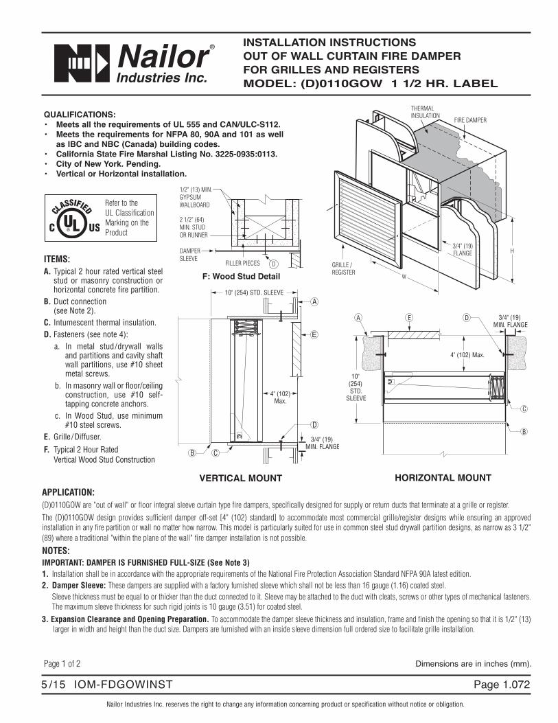
INSTALLATION INSTRUCTIONS OUT OF WALL CURTAIN FIRE DAMPER FOR GRILLES AND REGISTERSMODEL: (D)0110GOW 1 1/2 HR. LABEL
Nailor Industries Inc. reserves the right to change any information concerning product or specification without notice or obligation.
10" (254) STD. SLEEVE
3/4" (19) MIN. FLANGE
A
B C
D
E
4" (102) Max.
10" (254) STD.
SLEEVE
3/4" (19) MIN. FLANGE
A
B
C
E D
4" (102) Max.
HORIZONTAL MOUNTVERTICAL MOUNTAPPLICATION:(D)0110GOW are "out of wall" or floor integral sleeve curtain type fire dampers, specifically designed for supply or return ducts that terminate at a grille or register.The (D)0110GOW design provides sufficient damper off-set [4" (102) standard] to accommodate most commercial grille/register designs while ensuring an approvedinstallation in any fire partition or wall no matter how narrow. This model is particularly suited for use in common steel stud drywall partition designs, as narrow as 3 1/2"(89) where a traditional "within the plane of the wall" fire damper installation is not possible.
NOTES:IMPORTANT: DAMPER IS FURNISHED FULL-SIZE (See Note 3)1. Installation shall be in accordance with the appropriate requirements of the National Fire Protection Association Standard NFPA 90A latest edition.2. Damper Sleeve: These dampers are supplied with a factory furnished sleeve which shall not be less than 16 gauge (1.16) coated steel.
Sleeve thickness must be equal to or thicker than the duct connected to it. Sleeve may be attached to the duct with cleats, screws or other types of mechanical fasteners.The maximum sleeve thickness for such rigid joints is 10 gauge (3.51) for coated steel.
3. Expansion Clearance and Opening Preparation. To accommodate the damper sleeve thickness and insulation, frame and finish the opening so that it is 1/2" (13)larger in width and height than the duct size. Dampers are furnished with an inside sleeve dimension full ordered size to facilitate grille installation.
W
H3/4" (19)FLANGE
FIRE DAMPER
GRILLE / REGISTER
THERMALINSULATION
Dimensions are in inches (mm).Page 1 of 2
QUALIFICATIONS:• Meets all the requirements of UL 555 and CAN/ULC-S112.• Meets the requirements for NFPA 80, 90A and 101 as well
as IBC and NBC (Canada) building codes.• California State Fire Marshal Listing No. 3225-0935:0113.• City of New York. Pending.• Vertical or Horizontal installation.
ITEMS:A. Typical 2 hour rated vertical steel
stud or masonry construction orhorizontal concrete fire partition.
B. Duct connection(see Note 2).
C. Intumescent thermal insulation.D. Fasteners (see note 4):
a. In metal stud/drywall wallsand partitions and cavity shaftwall partitions, use #10 sheetmetal screws.
b. In masonry wall or floor/ceilingconstruction, use #10 self-tapping concrete anchors.
c. In Wood Stud, use minimum#10 steel screws.
E. Grille /Diffuser.
F. Typical 2 Hour Rated Vertical Wood Stud Construction
Refer to theUL ClassificationMarking on theProduct
1/2" (13) MIN. GYPSUM WALLBOARD
FILLER PIECES D
DAMPERSLEEVE
F: Wood Stud Detail
2 1/2" (64)MIN. STUD OR RUNNER

Page 1.073 5 /15 IOM-FDGOWINST"Comp l e t e A i r C o n t r o l a n d D i s t r i b u t i o n S o l u t i o n s . " www . n a i l o r . c om
Calgary, CanadaTel: 403-279-8619Fax: 403-279-5035
Houston, TexasTel: 281-590-1172Fax: 281-590-3086
Toronto, CanadaTel: 416-744-3300Fax: 416-744-3360
Las Vegas, NevadaTel: 702-648-5400Fax: 702-638-0400
4. Fasteners and Retaining Angles. For installation in a masonry wall or floor/ceiling and metal stud drywall partitions, no rear retaining angles are required. Insertdamper/sleeve combination into opening so that the 3/4" (19) flange is tight to the drywall or concrete. Secure the damper in the wall opening from inside the sleeve asshown above by use of the following:a. In metal stud/drywall walls, partitions and cavity shaft wall partitions, use minimum #10 sheet metal screws.b. In masonry walls or floor/ceilings use minimum #10 self-tapping concrete wall anchors. Anchors must penetrate wall or floor a minimum of 1 1/2" (38).c. In wood stud, use minimum #10 steel screws, 2 1/2" (64) long with minimum 1 1/2" (38) penetration into framing.Fasteners shall be spaced a maximum of 6" (152) on center and 2" (51) maximum from corners, a minimum of two per side is required.Alternatively, 1 1/2" x 1 1/2" x 16 gauge (38 x 38 x 1.61) rear retaining angles may be used in lieu of the above prescribed method and secured to the sleeve with 1/2"(12.7) long welds, 1/4" (6.35) dia. bolts and nuts, 3/16" (4.76) dia. steel rivets or #8 sheet metal screws, 8" (203) on center and 2" (51) maximum from corner of sleeveon all four sides.5. Maximum Size Limitations:
Model System Mounting Single Section Multiple Section0110GOW Static Vertical or 36" x 24" (914 x 610) __
HorizontalD0110GOW Dynamic Vertical 24" x 24" (610 x 610) 36" x 24" (914 x 610)
Horizontal 24" x 24" (610 x 610) __
*Maximum individual sections not to exceed 18" x 24" (457 x 610).IMPORTANTDO NOT CAST DAMPER IN PLACE.DO NOT INSTALL DAMPER OUT OF SQUARE OR OUT OF FLAT.REFER TO THE APPROPRIATE NAILOR INSTALLATION INSTRUCTION SUPPLEMENTS FOR ADDITIONAL INFORMATION OR SPECIAL REQUIREMENTS:STEEL AND WOOD STUD FRAMING FDSWSFINSTCAVITY SHAFT WALL PARTITIONS FDCSWINSTFLANGED TYPE ALTERNATIVE BREAKAWAY CONNECTIONS FDFABCQUICK-SET RETAINING ANGLES FDQSRA
Page 2 of 2Dimensions are in inches (mm).
*

Nailor Industries Inc. reserves the right to change any information concerning product or specification without notice or obligation.
Page 1.0803/16 IOM-FDIMP
OPERATION AND MAINTENANCE PROCEDURESCURTAIN TYPE FIRE DAMPERSMODEL SERIES: (D)0100, 0200, 0300 AND (D)0500
Page 1 of 2
Dampers are an essential part of the fire protection system in a building. The NFPA recommends that fire dampers betested periodically to verify the operational abilities of each installed damper. See NFPA 80, Standard for Fire Doors andOther Opening Protectives, for Operational Test and Periodic Inspection and Testing details.CAUTION:Some curtain fire dampers utilize high torque springs under tension; ensure HVAC fans are turned off. Testing springassisted fire dampers under airflow conditions is NOT RECOMMENDED and may severely damage or destroy ductwork.Use protective eyewear or safety glasses. Keep hands out of the blade path, as this can cause serious injury. Keep anyhard objects or tools out of the blade path as they can damage the blades when closing.
Periodic Inspection, Testing and MaintenanceConsult your local building code to verify whether there is a required maintenance and testing schedule. Most localjurisdictions reference NFPA 80 for Fire Dampers. Per NFPA 80, each damper should be tested and inspected 1 year afterinstallation and then every 4 years, except for hospitals, where the frequency is every 6 years.
1. Remove any obstructions, dirt, rust, corrosion, or other observed conditions that could impede proper damper operation.
2. Check closure springs (if applicable). If damaged or defective, repair or replace.
3a. Non-Spring Assisted DampersBend metal straps away from damper frame so that they are straight. Removefusible link and allow the blade package to drop and close naturally by the forceof gravity. See Detail 1. Use caution, keeping fingers, hands, arms and tools outof the blade path.
3b. Dynamic Rated or Spring Assisted DampersAS SOON AS THE LINK HAS BEEN REMOVED, THE SPRING WILL FORCE THEBLADES TO CLOSE INSTANTANEOUSLY. THE BLADE PATH MUST BE KEPTCLEAR.
4. Ensure the damper closes completely, without assistance. If the damper designincorporates a locking ramp to hold the damper in the fully closed position,confirm that the ramp locks properly.
5. Clean damper blades and other moving parts if necessary. Use of a mild detergent or solvents is recommended forany cleaning required. Lubricate moving parts with a dry lubricant (such as T.F.E. Dry Lube). Never use a regularlubricating oil on dampers, as it will attract dirt and grit.
6. Lift the blade package to the top of the damper to reopen and replace the fusible link. Take care not to rack, deformor damage the blades when reopening.
Reopening spring assisted fire dampers may be extremely difficult and in some cases, impossible.If it is determined that the damper is impossible or impractical to test or reopen, a thorough examination of the blade pathis required to ensure that nothing will prevent the damper from closing. Common obstructions include: racked damperframes, retaining angle installation screws, construction debris and contaminants.
7. Slide the replacement fusible link onto the metal straps. When replacing the fusible link, make sure it is the sametemperature rating of the link you are replacing. If a different temperature, contact factory. Install fusible link so thatthe temperature rating is facing outward and is visible.
8. Bend the metal straps up to hold the fusible link in place.
Detail 1
Page"Comp l e t e A i r C o n t r o l a n d D i s t r i b u t i o n S o l u t i o n s . " www . n a i l o r . c om
Calgary, CanadaTel: 403-279-8619Fax: 403-279-5035
Houston, TexasTel: 281-590-1172Fax: 281-590-3086
Toronto, CanadaTel: 416-744-3300Fax: 416-744-3360
Las Vegas, NevadaTel: 702-648-5400Fax: 702-638-0400
"Comp l e t e A i r C o n t r o l a n d D i s t r i b u t i o n S o l u t i o n s . "Page 1.081 3/16 IOM-FDIMP
Page 2 of 2
Receiving, Storage, PreparationUpon delivery, inspect shipping containers and contents closely. Note any damages on freight carrier’s delivery receipt.Store dampers in a cool, dry and safe location in an orderly manner away from construction site, warehouse traffic, othermaterials, etc. Cover with plastic sheeting to protect from excessive moisture, dirt and debris.Inspect dampers prior to installation. Dampers must be cleaned per procedures outlined in this document prior toinstallation if dirt, rust or corrosion is observed.
Page 1.0305/02 IOM-FDSC
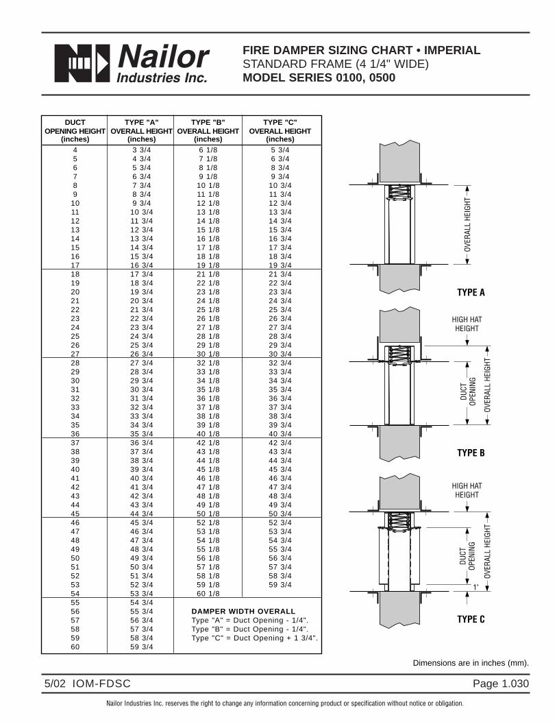
FIRE DAMPER SIZING CHART • IMPERIALSTANDARD FRAME (4 1/4" WIDE)MODEL SERIES 0100, 0500
Nailor Industries Inc. reserves the right to change any information concerning product or specification without notice or obligation.
HIGH HATHEIGHT
OVER
ALL
HEIG
HT
DUCT
OPEN
ING
1"
TYPE C
OVER
ALL
HEIG
HT
TYPE A
HIGH HATHEIGHT
OVER
ALL
HEIG
HT
DUCT
OPEN
ING
TYPE B
DUCT TYPE "A" TYPE "B" TYPE "C"OPENING HEIGHT OVERALL HEIGHT OVERALL HEIGHT OVERALL HEIGHT
(inches) (inches) (inches) (inches)4 3 3/4 6 1/8 5 3/45 4 3/4 7 1/8 6 3/46 5 3/4 8 1/8 8 3/47 6 3/4 9 1/8 9 3/48 7 3/4 10 1/8 10 3/49 8 3/4 11 1/8 11 3/4
10 9 3/4 12 1/8 12 3/411 10 3/4 13 1/8 13 3/412 11 3/4 14 1/8 14 3/413 12 3/4 15 1/8 15 3/414 13 3/4 16 1/8 16 3/415 14 3/4 17 1/8 17 3/416 15 3/4 18 1/8 18 3/417 16 3/4 19 1/8 19 3/418 17 3/4 21 1/8 21 3/419 18 3/4 22 1/8 22 3/420 19 3/4 23 1/8 23 3/421 20 3/4 24 1/8 24 3/422 21 3/4 25 1/8 25 3/423 22 3/4 26 1/8 26 3/424 23 3/4 27 1/8 27 3/425 24 3/4 28 1/8 28 3/426 25 3/4 29 1/8 29 3/427 26 3/4 30 1/8 30 3/428 27 3/4 32 1/8 32 3/429 28 3/4 33 1/8 33 3/430 29 3/4 34 1/8 34 3/431 30 3/4 35 1/8 35 3/432 31 3/4 36 1/8 36 3/433 32 3/4 37 1/8 37 3/434 33 3/4 38 1/8 38 3/435 34 3/4 39 1/8 39 3/436 35 3/4 40 1/8 40 3/437 36 3/4 42 1/8 42 3/438 37 3/4 43 1/8 43 3/439 38 3/4 44 1/8 44 3/440 39 3/4 45 1/8 45 3/441 40 3/4 46 1/8 46 3/442 41 3/4 47 1/8 47 3/443 42 3/4 48 1/8 48 3/444 43 3/4 49 1/8 49 3/445 44 3/4 50 1/8 50 3/446 45 3/4 52 1/8 52 3/447 46 3/4 53 1/8 53 3/448 47 3/4 54 1/8 54 3/449 48 3/4 55 1/8 55 3/450 49 3/4 56 1/8 56 3/451 50 3/4 57 1/8 57 3/452 51 3/4 58 1/8 58 3/453 52 3/4 59 1/8 59 3/454 53 3/4 60 1/855 54 3/456 55 3/4 DAMPER WIDTH OVERALL57 56 3/4 Type "A" = Duct Opening - 1/4".58 57 3/4 Type "B" = Duct Opening - 1/4".59 58 3/4 Type "C" = Duct Opening + 1 3/4".60 59 3/4
Dimensions are in inches (mm).

Page 1.031 5/02 IOM-FDSC
" C o m p l e t e A i r C o n t r o l a n d D i s t r i b u t i o n S o l u t i o n s . " w w w . n a i l o r . c o m
Calgary, CanadaTel: 403-279-8619Fax: 403-279-5035
Ft. Lauderdale, FloridaTel: 954-351-2444Fax: 954-351-2440
Houston, TexasTel: 281-590-1172Fax: 281-590-3086
Toronto, CanadaTel: 416-744-3300Fax: 416-744-3360
Nailor Industries Inc. reserves the right to change any information concerning product or specification without notice or obligation.
Page 3.0408/07 IOM-FDCSWINST
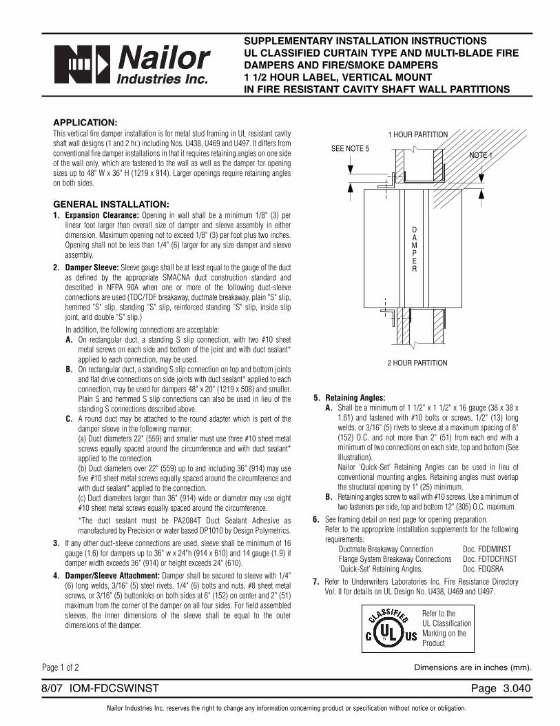
SUPPLEMENTARY INSTALLATION INSTRUCTIONSUL CLASSIFIED CURTAIN TYPE AND MULTI-BLADE FIREDAMPERS AND FIRE/SMOKE DAMPERS 1 1/2 HOUR LABEL, VERTICAL MOUNT IN FIRE RESISTANT CAVITY SHAFT WALL PARTITIONS
APPLICATION:This vertical fire damper installation is for metal stud framing in UL resistant cavityshaft wall designs (1 and 2 hr.) including Nos. U438, U469 and U497. It differs fromconventional fire damper installations in that it requires retaining angles on one sideof the wall only, which are fastened to the wall as well as the damper for openingsizes up to 48" W x 36" H (1219 x 914). Larger openings require retaining angleson both sides.
GENERAL INSTALLATION:1. Expansion Clearance: Opening in wall shall be a minimum 1/8" (3) per
linear foot larger than overall size of damper and sleeve assembly in eitherdimension. Maximum opening not to exceed 1/8" (3) per foot plus two inches.Opening shall not be less than 1/4" (6) larger for any size damper and sleeveassembly.
2. Damper Sleeve: Sleeve gauge shall be at least equal to the gauge of the ductas defined by the appropriate SMACNA duct construction standard anddescribed in NFPA 90A when one or more of the following duct-sleeveconnections are used (TDC/TDF breakaway, ductmate breakaway, plain "S" slip,hemmed "S" slip, standing "S" slip, reinforced standing "S" slip, inside slipjoint, and double "S" slip.)In addition, the following connections are acceptable:A. On rectangular duct, a standing S slip connection, with two #10 sheet
metal screws on each side and bottom of the joint and with duct sealant*applied to each connection, may be used.
B. On rectangular duct, a standing S slip connection on top and bottom jointsand flat drive connections on side joints with duct sealant* applied to eachconnection, may be used for dampers 48" x 20" (1219 x 508) and smaller.Plain S and hemmed S slip connections can also be used in lieu of thestanding S connections described above.
C. A round duct may be attached to the round adapter which is part of thedamper sleeve in the following manner:(a) Duct diameters 22" (559) and smaller must use three #10 sheet metalscrews equally spaced around the circumference and with duct sealant*applied to the connection.(b) Duct diameters over 22" (559) up to and including 36" (914) may usefive #10 sheet metal screws equally spaced around the circumference andwith duct sealant* applied to the connection.(c) Duct diameters larger than 36" (914) wide or diameter may use eight#10 sheet metal screws equally spaced around the circumference.*The duct sealant must be PA2084T Duct Sealant Adhesive asmanufactured by Precision or water based DP1010 by Design Polymetrics.
3. If any other duct-sleeve connections are used, sleeve shall be minimum of 16gauge (1.6) for dampers up to 36" w x 24"h (914 x 610) and 14 gauge (1.9) ifdamper width exceeds 36" (914) or height exceeds 24" (610).
4. Damper/Sleeve Attachment: Damper shall be secured to sleeve with 1/4"(6) long welds, 3/16" (5) steel rivets, 1/4" (6) bolts and nuts, #8 sheet metalscrews, or 3/16" (5) buttonloks on both sides at 6" (152) on center and 2" (51)maximum from the corner of the damper on all four sides. For field assembledsleeves, the inner dimensions of the sleeve shall be equal to the outerdimensions of the damper.
NOTE 1SEE NOTE 5
DAMPER
1 HOUR PARTITION
2 HOUR PARTITION
5. Retaining Angles:A. Shall be a minimum of 1 1/2" x 1 1/2" x 16 gauge (38 x 38 x
1.61) and fastened with #10 bolts or screws, 1/2" (13) longwelds, or 3/16" (5) rivets to sleeve at a maximum spacing of 8"(152) O.C. and not more than 2" (51) from each end with aminimum of two connections on each side, top and bottom (SeeIllustration).Nailor 'Quick-Set' Retaining Angles can be used in lieu ofconventional mounting angles. Retaining angles must overlapthe structural opening by 1" (25) minimum.
B. Retaining angles screw to wall with #10 screws. Use a minimum oftwo fasteners per side, top and bottom 12" (305) O.C. maximum.
6. See framing detail on next page for opening preparation.Refer to the appropriate installation supplements for the followingrequirements:
Ductmate Breakaway Connection Doc. FDDMINSTFlange System Breakaway Connections Doc. FDTDCFINST'Quick-Set' Retaining Angles. Doc. FDQSRA
7. Refer to Underwriters Laboratories Inc. Fire Resistance DirectoryVol. II for details on UL Design No. U438, U469 and U497.
Page 1 of 2 Dimensions are in inches (mm).
Refer to theUL ClassificationMarking on theProduct
Page
" C o m p l e t e A i r C o n t r o l a n d D i s t r i b u t i o n S o l u t i o n s . " w w w . n a i l o r . c o m
Calgary, CanadaTel: 403-279-8619Fax: 403-279-5035
Houston, TexasTel: 281-590-1172Fax: 281-590-3086
Toronto, CanadaTel: 416-744-3300Fax: 416-744-3360
Las Vegas, NevadaTel: 702-648-5400Fax: 702-638-0400
" C o m p l e t e A i r C o n t r o l a n d D i s t r i b u t i o n S o l u t i o n s . "" C o m p l e t e A i r C o n t r o l a n d D i s t r i b u t i o n S o l u t i o n s . "" C o m p l e t e A i r C o n t r o l a n d D i s t r i b u t i o n S o l u t i o n s . "
Page 3.041 8/07 IOM-FDCSWINST
" C o m p l e t e A i r C o n t r o l a n d D i s t r i b u t i o n S o l u t i o n s . " w w w . n a i l o r . c o m
AA
BB
24" O.C. MAX.
CEILING J-RUNNER
DOUBLE E STUDS
C-H VENTED STUDS
FLOOR J-RUNNER
24" O.C. MAX.
24" O.C. MAX.
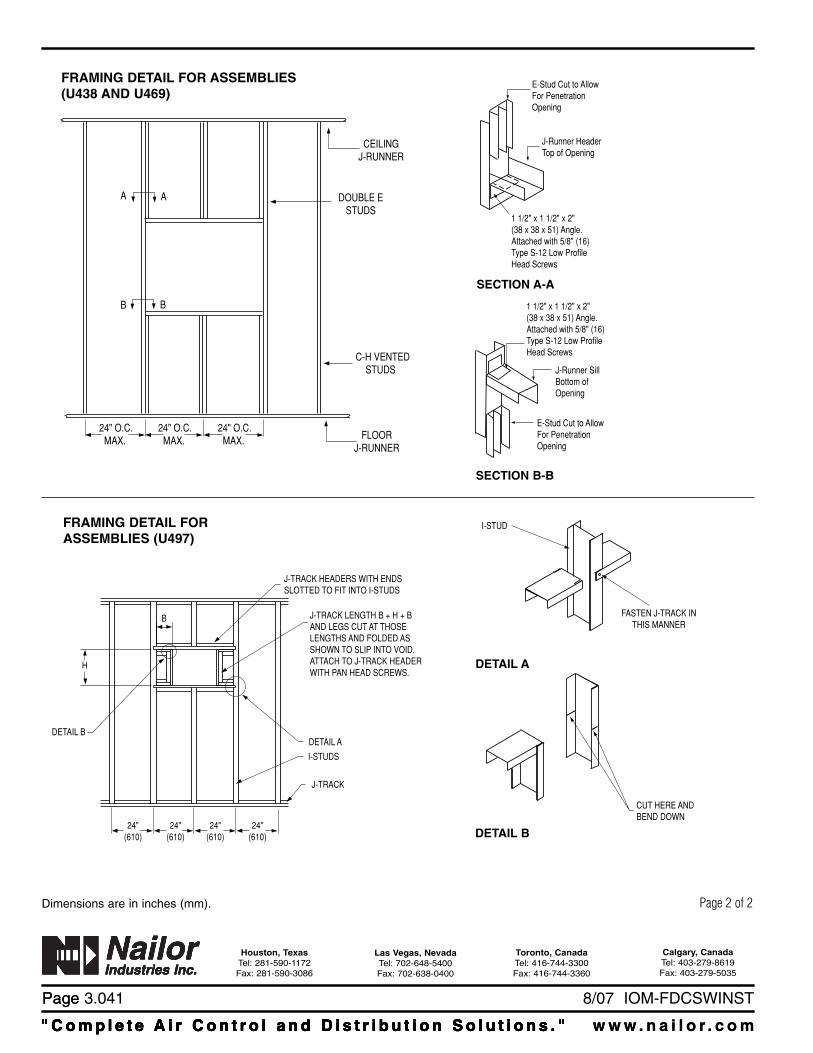
1 1/2" x 1 1/2" x 2"(38 x 38 x 51) Angle.Attached with 5/8" (16)Type S-12 Low ProfileHead Screws
E-Stud Cut to AllowFor PenetrationOpening
J-Runner HeaderTop of Opening
E-Stud Cut to AllowFor PenetrationOpening
1 1/2" x 1 1/2" x 2"(38 x 38 x 51) Angle. Attached with 5/8" (16)Type S-12 Low ProfileHead Screws
J-Runner SillBottom ofOpening
FRAMING DETAIL FOR ASSEMBLIES(U438 AND U469)
SECTION A-A
SECTION B-B
FRAMING DETAIL FORASSEMBLIES (U497)
DETAIL B
H
24"(610)
B
J-TRACK HEADERS WITH ENDSSLOTTED TO FIT INTO I-STUDS
J-TRACK LENGTH B + H + B AND LEGS CUT AT THOSELENGTHS AND FOLDED AS SHOWN TO SLIP INTO VOID.ATTACH TO J-TRACK HEADERWITH PAN HEAD SCREWS.
DETAIL A
I-STUDS
J-TRACK
24"(610)
24"(610)
24"(610)
I-STUD
FASTEN J-TRACK INTHIS MANNER
CUT HERE ANDBEND DOWN
DETAIL A
DETAIL B
Page 2 of 2Dimensions are in inches (mm).
Nailor Industries Inc. reserves the right to change any information concerning product or specification without notice or obligation.
Page 3.0922/05 IOM-FDEFS
Dimensions are in inches (mm).
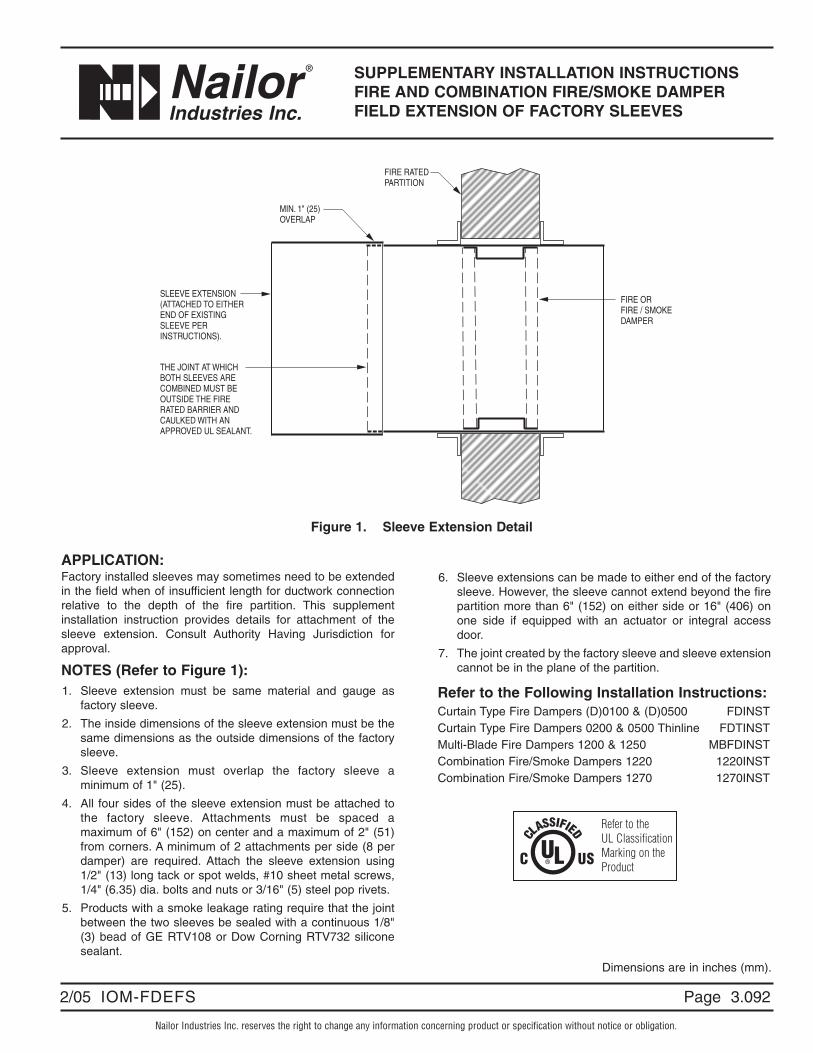
Figure 1. Sleeve Extension Detail
SUPPLEMENTARY INSTALLATION INSTRUCTIONSFIRE AND COMBINATION FIRE/SMOKE DAMPERFIELD EXTENSION OF FACTORY SLEEVES
APPLICATION:Factory installed sleeves may sometimes need to be extendedin the field when of insufficient length for ductwork connectionrelative to the depth of the fire partition. This supplementinstallation instruction provides details for attachment of thesleeve extension. Consult Authority Having Jurisdiction forapproval.
NOTES (Refer to Figure 1):1. Sleeve extension must be same material and gauge as
factory sleeve.
2. The inside dimensions of the sleeve extension must be thesame dimensions as the outside dimensions of the factorysleeve.
3. Sleeve extension must overlap the factory sleeve aminimum of 1" (25).
4. All four sides of the sleeve extension must be attached tothe factory sleeve. Attachments must be spaced amaximum of 6" (152) on center and a maximum of 2" (51)from corners. A minimum of 2 attachments per side (8 perdamper) are required. Attach the sleeve extension using1/2" (13) long tack or spot welds, #10 sheet metal screws,1/4" (6.35) dia. bolts and nuts or 3/16" (5) steel pop rivets.
5. Products with a smoke leakage rating require that the jointbetween the two sleeves be sealed with a continuous 1/8"(3) bead of GE RTV108 or Dow Corning RTV732 siliconesealant.
6. Sleeve extensions can be made to either end of the factorysleeve. However, the sleeve cannot extend beyond the firepartition more than 6" (152) on either side or 16" (406) onone side if equipped with an actuator or integral accessdoor.
7. The joint created by the factory sleeve and sleeve extensioncannot be in the plane of the partition.
Refer to the Following Installation Instructions:Curtain Type Fire Dampers (D)0100 & (D)0500 FDINSTCurtain Type Fire Dampers 0200 & 0500 Thinline FDTINSTMulti-Blade Fire Dampers 1200 & 1250 MBFDINSTCombination Fire/Smoke Dampers 1220 1220INSTCombination Fire/Smoke Dampers 1270 1270INST
THE JOINT AT WHICHBOTH SLEEVES ARECOMBINED MUST BEOUTSIDE THE FIRE RATED BARRIER ANDCAULKED WITH ANAPPROVED UL SEALANT.
SLEEVE EXTENSION(ATTACHED TO EITHEREND OF EXISTINGSLEEVE PERINSTRUCTIONS).
FIRE RATEDPARTITION
MIN. 1" (25)OVERLAP
FIRE ORFIRE / SMOKEDAMPER
Refer to theUL ClassificationMarking on theProduct

Page
" C o m p l e t e A i r C o n t r o l a n d D i s t r i b u t i o n S o l u t i o n s . " w w w . n a i l o r . c o m
Calgary, CanadaTel: 403-279-8619Fax: 403-279-5035
Houston, TexasTel: 281-590-1172Fax: 281-590-3086
Toronto, CanadaTel: 416-744-3300Fax: 416-744-3360
Las Vegas, NevadaTel: 702-648-5400Fax: 702-638-0400
Page 3.093 2/05 IOM-FDEFS
Page 1.0905/02 IOM-FDETL
CURTAIN FIRE DAMPER ACCESSORYELECTRO-THERMAL LINKMODEL: ETL
Nailor Industries Inc. reserves the right to change any information concerning product or specification without notice or obligation.
The Electro Thermal Link (ETL®) is a multi purpose,dual responsive fusible link which reacts (melts)when subjected to;1. Local heat (165°F (74°C)) exactly the same as anordinary link.2. External electrical impulse of low power and shortduration.It is specifically designed to substitute for ordinarylinks and/or actuators in existing and newinstallations of Fire Dampers, Fire Doors, FireExtinguishers, Fire and Smoke Roof Hatches,Sprinklers, Smoke Towers, and chemical or gasAutomatic Release Systems.The substitution should be made in every installationof the above devices where it is desirable to improvelife safety by making those devices responsive to -SMOKE in the early form of invisible products of
combustion through ionization detectors, orFIRE at an earlier stage than ordinary links thru
the use of rate of rise or maximumtemperature devices.
The ETL's electro-response is the unique feature. Itis not smoke responsive of itself, but its powerrequirement is so low that it can be released with anelectrical impulse from any smoke detector's powersource. It is compatible with every smoke detector onthe market in the United States today.
The operating range is 6 to 30 volts AC or DC, less than0.2 ampere of trip current required, and 1/2 millisecond(.0005 second) response at 24 v. The electricalresponse is a trigger for the chemical heating of thecenter element which is a self-contained exo-thermicreactor, yielding no noise, smoke, or gas - just quickheat to open the link in seven seconds.The ETL's thermal response is identical to that ofordinary fusible links of identical temperature (165°F(74°C)) and strength (40#) rating.In its capacity of converting a FIRE safety device into aFIRE/SMOKE safety device the ETL can be substitutedfor both an ordinary link and motor, or link and electro-magnetic operator with advantages of simplicity,economy, operational reliability and wide acceptability.With its dual responsiveness the ETL can be substitutedfor two other devices at a savings in first cost as well asoperating cost and maintenance. The ETL is a Space AgeDevice built to zero defect standards and to last at leastfifty years and then still react properly – only on fire orsmoke emergency. It is totally independent of powerfailures since it draws power from the detector standbysource if needed. The ETL is listed by Underwriter'sLaboratories, Inc. as a Fusible Link.With the ongoing development of dynamic smokecontrol systems and building code changes in recentyears, application and use of this product should begoverned by acceptance of the local authority havingjurisdiction.
ETL®
WHAT IT IS – WHAT IT DOES

Page 1.091 5/02 IOM-FDETL
" C o m p l e t e A i r C o n t r o l a n d D i s t r i b u t i o n S o l u t i o n s . " w w w . n a i l o r . c o m
Calgary, CanadaTel: 403-279-8619Fax: 403-279-5035
Ft. Lauderdale, FloridaTel: 954-351-2444Fax: 954-351-2440
Houston, TexasTel: 281-590-1172Fax: 281-590-3086
Toronto, CanadaTel: 416-744-3300Fax: 416-744-3360
Nailor Industries Inc. reserves the right to change any information concerning product or specification without notice or obligation.
Page 3.0803/19 IOM-FDS
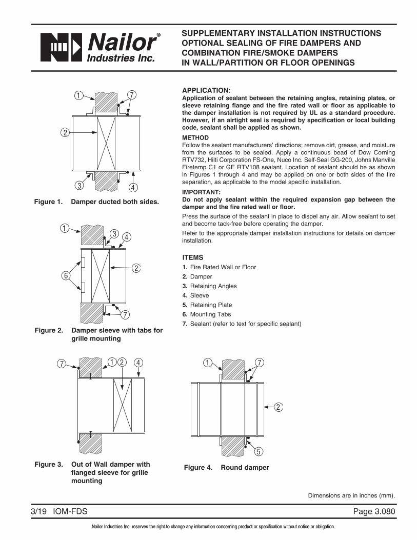
SUPPLEMENTARY INSTALLATION INSTRUCTIONSOPTIONAL SEALING OF FIRE DAMPERS AND COMBINATION FIRE/SMOKE DAMPERSIN WALL/PARTITION OR FLOOR OPENINGS
Nailor Industries Inc. reserves the right to change any information concerning product or specification without notice or obligation.
Dimensions are in inches (mm).
Figure 1. Damper ducted both sides.
ITEMS1. Fire Rated Wall or Floor2. Damper3. Retaining Angles4. Sleeve5. Retaining Plate6. Mounting Tabs7. Sealant (refer to text for specific sealant)
APPLICATION:Application of sealant between the retaining angles, retaining plates, or sleeve retaining flange and the fire rated wall or floor as applicable to the damper installation is not required by UL as a standard procedure. However, if an airtight seal is required by specification or local building code, sealant shall be applied as shown.
METHODFollow the sealant manufacturers’ directions; remove dirt, grease, and moisture from the surfaces to be sealed. Apply a continuous bead of Dow Corning RTV732, Hilti Corporation FS-One, Nuco Inc. Self-Seal GG-200, Johns Manville Firetemp C1 or GE RTV108 sealant. Location of sealant should be as shown in Figures 1 through 4 and may be applied on one or both sides of the fire separation, as applicable to the model specific installation.
IMPORTANT:Do not apply sealant within the required expansion gap between the damper and the fire rated wall or floor.Press the surface of the sealant in place to dispel any air. Allow sealant to set and become tack-free before operating the damper.Refer to the appropriate damper installation instructions for details on damper installation.
1
7
26
43
1 7
3 4
2
7 1 2 4 1 7
2
5
Figure 2. Damper sleeve with tabs for grille mounting
Figure 3. Out of Wall damper with flanged sleeve for grille mounting
Figure 4. Round damper

Page 3.081
“ C o m p l e t e A i r C o n t r o l a n d D i s t r i b u t i o n S o l u t i o n s . ” w w w . n a i l o r . c o m
Calgary, CanadaTel: 403-279-8619Fax: 403-279-5035
Houston, TexasTel: 281-590-1172Fax: 281-590-3086
Toronto, CanadaTel: 416-744-3300Fax: 416-744-3360
Las Vegas, NevadaTel: 702-648-5400Fax: 702-638-0400
3/19 IOM-FDS
" C o m p l e t e A i r C o n t r o l a n d D i s t r i b u t i o n S o l u t i o n s . "
Nailor Industries Inc. reserves the right to change any information concerning product or specification without notice or obligation.
Page 3.02011/13 IOM-FDSSRAINST
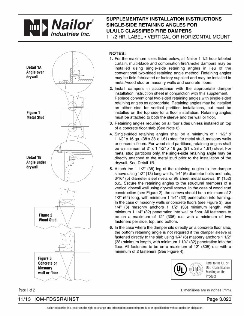
SUPPLEMENTARY INSTALLATION INSTRUCTIONS SINGLE-SIDE RETAINING ANGLES FOR UL/ULC CLASSIFIED FIRE DAMPERS1 1/2 HR. LABEL • VERTICAL OR HORIZONTAL MOUNT
Dimensions are in inches (mm).
NOTES:1. For the maximum sizes listed below, all Nailor 1 1/2 hour labeled
curtain, multi-blade and combination fire/smoke dampers may beinstalled using single-side retaining angles in lieu of theconventional two-sided retaining angle method. Retaining anglesmay be field fabricated or factory supplied and may be installed inmetal/wood stud or masonry walls and concrete floors.
2. Install dampers in accordance with the appropriate damperinstallation instruction sheet in conjunction with this supplement. Replace conventional two-sided retaining angles with single-sidedretaining angles as appropriate. Retaining angles may be installedon either side for vertical partition installations, but must beinstalled on the top side for a floor installation. Retaining anglesmust be attached to both the sleeve and the wall or floor.
3. Retaining angles required on all four sides unless installed on topof a concrete floor slab (See Note 6).
4. Single-sided retaining angles shall be a minimum of 1 1/2" x 1 1/2" x 16 ga. (38 x 38 x 1.61) steel for metal stud, masonry wallsor concrete floors. For wood stud partitions, retaining angles shallbe a minimum of 2" x 1 1/2" x 16 ga. (51 x 38 x 1.61) steel. Formetal stud partitions only, the single-side retaining angle may bedirectly attached to the metal stud prior to the installation of thedrywall. See Detail 1B.
5. Attach the 1 1/2" (38) leg of the retaining angles to the dampersleeve using 1/2" (13) long welds, 1/4" (6) diameter bolts and nuts,3/16" (5) diameter steel rivets or #8 sheet metal screws, 6" (152)o.c.. Secure the retaining angles to the structural members of avertical drywall wall using drywall screws. In the case of wood studconstruction (see Figure 2), the screws should be a minimum of 21/2" (64) long, with minimum 1 1/4" (32) penetration into framing.In the case of masonry walls or concrete floors (see Figure 3), use1/4" (6) masonry anchors 1 1/2" (38) minimum length, withminimum 1 1/4" (32) penetration into wall or floor. All fasteners tobe on a maximum of 12" (305) o.c. with a minimum of twofasteners per side, top, and bottom.
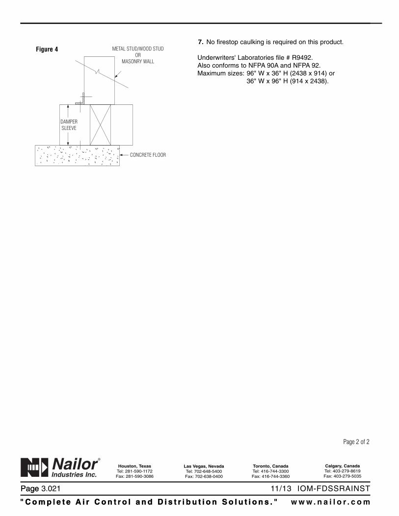
6. In the case where the damper sits directly on a concrete floor slab,the bottom retaining angle is not required if the damper sleeve isfastened directly to the slab using 1/4" (6) masonry anchors 1 1/2"(38) minimum length, with minimum 1 1/4" (32) penetration into thefloor. All fasteners to be on a maximum of 12" (305) o.c. with aminimum of 2 fasteners (See Figure 4).
Detail 1AAngle overdrywall.
Figure 1Metal Stud
Detail 1BAngle underdrywall.
Figure 2Wood Stud
Figure 3Concrete orMasonrywall or floor
Refer to the UL or ULC ClassificationMarking on theProduct
Page 1 of 2
Page
" C o m p l e t e A i r C o n t r o l a n d D i s t r i b u t i o n S o l u t i o n s . " w w w . n a i l o r . c o m
Calgary, CanadaTel: 403-279-8619Fax: 403-279-5035
Houston, TexasTel: 281-590-1172Fax: 281-590-3086
Toronto, CanadaTel: 416-744-3300Fax: 416-744-3360
Las Vegas, NevadaTel: 702-648-5400Fax: 702-638-0400
" C o m p l e t e A i r C o n t r o l a n d D i s t r i b u t i o n S o l u t i o n s . "
Page 3.021 11/13 IOM-FDSSRAINST
7. No firestop caulking is required on this product.
Underwriters' Laboratories file # R9492.Also conforms to NFPA 90A and NFPA 92.Maximum sizes: 96" W x 36" H (2438 x 914) or
36" W x 96" H (914 x 2438).
Figure 4 METAL STUD/WOOD STUDOR
MASONRY WALL
CONCRETE FLOOR
DAMPERSLEEVE
Page 2 of 2

Nailor Industries Inc. reserves the right to change any information concerning product or specification without notice or obligation.
Page 3.0301/12 IOM-FDSWSFINST
SUPPLEMENTARY INSTALLATION INSTRUCTIONSSTEEL AND WOOD STUD FRAMING FOR FIREDAMPERS IN DRYWALL PARTITIONS(CURTAIN TYPE, MULTI-BLADE AND COMBINATION FIRE/SMOKE)
RUNNER90° BEND
FLOORRUNNER
2" (51)
2" (51)
AA12"
(304)
MAX.
(METALSTUDS)
MAX.
24" (610) O.C. 24" (610) O.C.
MAX.
24" (610) O.C.
O.C. MAX.(WOODEN STUDS)
CEILINGRUNNER
2 FASTENERS(SEE NOTE 4)
DOUBLE STUD
16" (406)
NOTES:1. These details are based upon tests conducted by the
Gypsum Association. Consult the local authority havingjurisdiction for other acceptable framing methods.
2. Frame wall openings as shown in Figure 1 or 2.
3. Gypsum panels must be screwed to all stud and runnerflanges, 12" (305) max. o.c. surrounding opening.
4. All fasteners to be per UL/ULC Classified wall design.
5. UL/ULC wood stud designs require gypsum wallboardfiller pieces to be installed around entire opening,screwed 12" (305) o.c. to web of runners and studs,covering all wood stud surfaces.In UL metal stud designs, exposed steel surfaces neednot be covered with gypsum wallboard. ULC metal studconstruction however may still require filler pieces,check with the local authorities.
6. Refer to standard installation instructions sheet foradditional details.
2 1/2" (64) STUDS MINIMUM
2 1/2" (64) RUNNER MINIMUM
SCREWSFraming DetailSection A-A
Dimensions are in inches (mm).
FLOORRUNNER
DETAIL A
MAX.
24" (610) O.C.
CEILINGRUNNER
METALSTUDFRAMINGSHOWN
NOTCHEDPIECEBENTDOWN
Detail A
Page 1 of 2
FIGURE 2. DOUBLE VERTICAL STUD OPENING PREPARATION DETAILS.DAMPERS OVER 36" x 36" (914 x 914).
FIGURE 1. SINGLE VERTICAL STUD OPENING PREPARATION DETAILS.DAMPERS UP TO 36" x 36" (914 x 914).

Page
"Comp l e t e A i r C o n t r o l a n d D i s t r i b u t i o n S o l u t i o n s . " www . n a i l o r . c om
Calgary, CanadaTel: 403-279-8619Fax: 403-279-5035
Houston, TexasTel: 281-590-1172Fax: 281-590-3086
Toronto, CanadaTel: 416-744-3300Fax: 416-744-3360
Las Vegas, NevadaTel: 702-648-5400Fax: 702-638-0400
"Comp l e t e A i r C o n t r o l a n d D i s t r i b u t i o n S o l u t i o n s . "
Page 3.031 1/12 IOM-FDSWSFINST
WOOD STUD DETAIL1/2" (13) MIN. GYPSUM WALLBOARD
RETAINING ANGLE
FILLER PIECES
DAMPER SLEEVE
2 Hour Partition Rating
2 1/2" (64) MIN.STUD OR RUNNER 1" (25) MIN.
METAL STUD DETAIL (UL DESIGN)
2 Hour Partition Rating
GYPSUM WALLBOARD
RETAINING ANGLE
DAMPER SLEEVE
STUD OR RUNNER 1" (25) MIN.
1/2" (13) MIN. GYPSUM WALLBOARD
1 1/2" (38)MINERAL FIBERBLANKET IN CAVITY,IF REQUIREDRETAINING ANGLE
FILLER PIECES
DAMPER SLEEVE
1 Hour Partition Rating
2 1/2" (64) MIN.STUD OR RUNNER 1" (25) MIN.
GYPSUM WALLBOARD
RETAINING ANGLE
DAMPER SLEEVE
1 Hour Partition Rating
STUD OR RUNNER 1" (25) MIN.
Page 2 of 2Dimensions are in inches (mm).
TYPICAL STUD WALL DETAILS (See Notes on Page 1)

Nailor Industries Inc. reserves the right to change any information concerning product or specification without notice or obligation.
Page 2.0845 /17 IOM-FSDST
SLEEVE TRIMMING OF FIRE AND COMBINATIONFIRE/SMOKE DAMPERS INSTALLATION INSTRUCTIONS
Page 1 of 2
SLEEVE LENGTH
TRIM TRIM
16" (406) MAX.6" (203)MAX.
TRIM TRIM
SLEEVE LENGTH
Trimming of factory-supplied sleeves may be necessary toaccommodate field conditions or applications. Other dampercomponents such as actuators and fuse links should not bealtered.
NOTES:1. Sleeve Length on Non-actuator side: 6" (152) maximum
sleeve length beyond fire-rated barrier on non-actuator side.2. Sleeve Length on Actuator side: 16" (406) maximum sleeve
length beyond fire-rated barrier on actuator side.
Dimensions are in inches (mm).

Page 2.085 5 /17 IOM-FSDST"Comp l e t e A i r C o n t r o l a n d D i s t r i b u t i o n S o l u t i o n s . " www . n a i l o r . c om
Calgary, CanadaTel: 403-279-8619Fax: 403-279-5035
Houston, TexasTel: 281-590-1172Fax: 281-590-3086
Toronto, CanadaTel: 416-744-3300Fax: 416-744-3360
Las Vegas, NevadaTel: 702-648-5400Fax: 702-638-0400
Page 2 of 2