Embed Size (px)
Citation preview

Self-Stabilizing Quad-Rotor Helicopter
Jared Rought, Daniel Goodhew, John Sullivan and Angel Rodriguez
Department of Electrical Engineering and Computer Science, University of Central
Florida, Orlando, Florida, 32816
Abstract — Unmanned aerial vehicles are gaining in popularity both as useful work tools and as entertaining toys. This paper focuses on the design and construction of both hardware and software for a quadruple rotor copter. The copter is intended to be a lightweight, cost conscious design. Software components include the stabilization loop, communication among the microcontroller and the motors, and communication with the iPhone controller.
Index Terms — Inertial Measurement Unit, Control Theory, Directional Cosine Matrix
I. Introduction
Unmanned Aerial Vehicles have played a crucial role in modern warfare, reducing both cost and human liability. This reduction in cost has been relative and does not offer much for non-defense firms and the general public. The aim of the project is to create a lightweight, low cost, easy to use UAV for various applications. Such a device could have applications in areas such as warfare reconnaissance or for civilian uses such as for humanitarian aid, surveying missions, or amusement purposes.
The quad-copter incorporates a medium to low power usage design running off of battery power. Two batteries are incorporated into the design, one low power and one medium power, to maintain a clean source for the electronic boards. The main drain to the power source is from the motors necessary to lift the aircraft off the ground and maintain stability. As with all aircraft, it is essential to reduce weight; therefore, all components are lightweight to accommodate for less power consuming motors. The use of smaller motors allows for increased flight time due to a reduction in power consumption. The main frame of the quad-copter is constructed from lightweight aluminum tubing and designed to provide the largest possible stability to the aircraft.
In order to maximize the stability of the aircraft, an Inertial Measurement Unit (IMU) is used to regulate and compensate for aircraft movements. The IMU tracks altitude, speed, position, direction and log the data. This
information is then used to stabilize the aircraft and support other features of the craft.
The central controller is the interface for all of the modules on the quad-copter. It is be capable of receiving the data from the IMU and data sent from the user to control the modules responsible for changing motor speed. The central board, with the central processor mounted on it, has pin headers so that the other modules can be connected by wire to the central controller. Connecting the modules in this manner allows for damaged modules to be easily removed and replaced. This also allows for modules to be upgraded or changed based on user preferences.
II. Overview of Orientation Tracking
There are many ways in which to derive the orientation of the system, one of which is called a Directional Cosine Matrix (DCM). The DCM presents a rotational matrix that can be used to describe the attitude of the system being analyzed [2]. Directional cosine matrices are used to transform one reference frame to another [2]. In the case of the helicopter, the reference frames are earth and the aircraft. Directional cosines are essentially a representation of a vector. For example, take a vector that is present in the XY plane. The vector can be
represented by directional cosines.The most important aspect of the directional cosine
matrix is the data that resides with in the matrix. The matrix is comprised of the angle that is formed between the vector and the coordinate axis [1]. Rotational matrices can then be used to transform between two types of reference frames. Each row of the rotational matrix presents the unit vector as seen by the other reference frame, in the case the earths. To transform a vector to the other reference frame you must multiply that vector by the rotational matrix. Care must be taken when using matrix multiplication due to the fact that matrix multiplication is not commutative [1], meaning…
(1)

Each row of the rotational matrix describes the presents the aircrafts rotational vector as seen by earth’s reference frame [1]. The directional cosine representation for the vector with regards to the earth’s reference frame, as seen by each individual axis. For example, take the vector . This vector is comprised of a component in the X-axis,
It is important to note that the magnitude of the vector is equal to 1. This vector is called a unit vector and is
the fundamental reason that you are able to multiply any vector by the rotational matrix, to describe the orientation[1]. Since the vector’s magnitude is only one, the multiplication changes the orientation of the vector, without modifying the magnitude.
The order of rotation is also important to describing the orientation of a vector. Using the Euler angles (Φ, θ, and ψ), an order of rotation must be selected. For example if the order ZYX is followed for rotations corresponding to ψ=45 θ=90 Φ=45, the following rotations result in a vector pointing in an equal but opposite direction to a rotation of Φ=45 θ=90 ψ=45. It is for this reason that the standard order of rotations is taken to be XYZ, for all calculations.
The rotational matrix can then be multiplied by the ground reference vector to derive the aircrafts orientation.[1] Conversely due to the orthogonality of the ground matrix and the rotational matrix; the matrix created by this multiplication can be multiplied by the inverse of the rotational matrix to realize the ground reference matrix.
The rotational matrix is updated by integrating the kinematic equation that describes the rotation of the ridged body being analyzed. The gyroscopes out put a voltage that is proportional to the rate of rotation that is being experienced by the aircraft.
The rate of rotation is equal to…
ω(t) = rate of rotation (gyro output)
This equation is then integrated to produce the following equation.
The equation equates to the following numerical integration that is preformed on each row of the rotational matrix.
A generalized form yields…
III. DCM Algorithm Realization
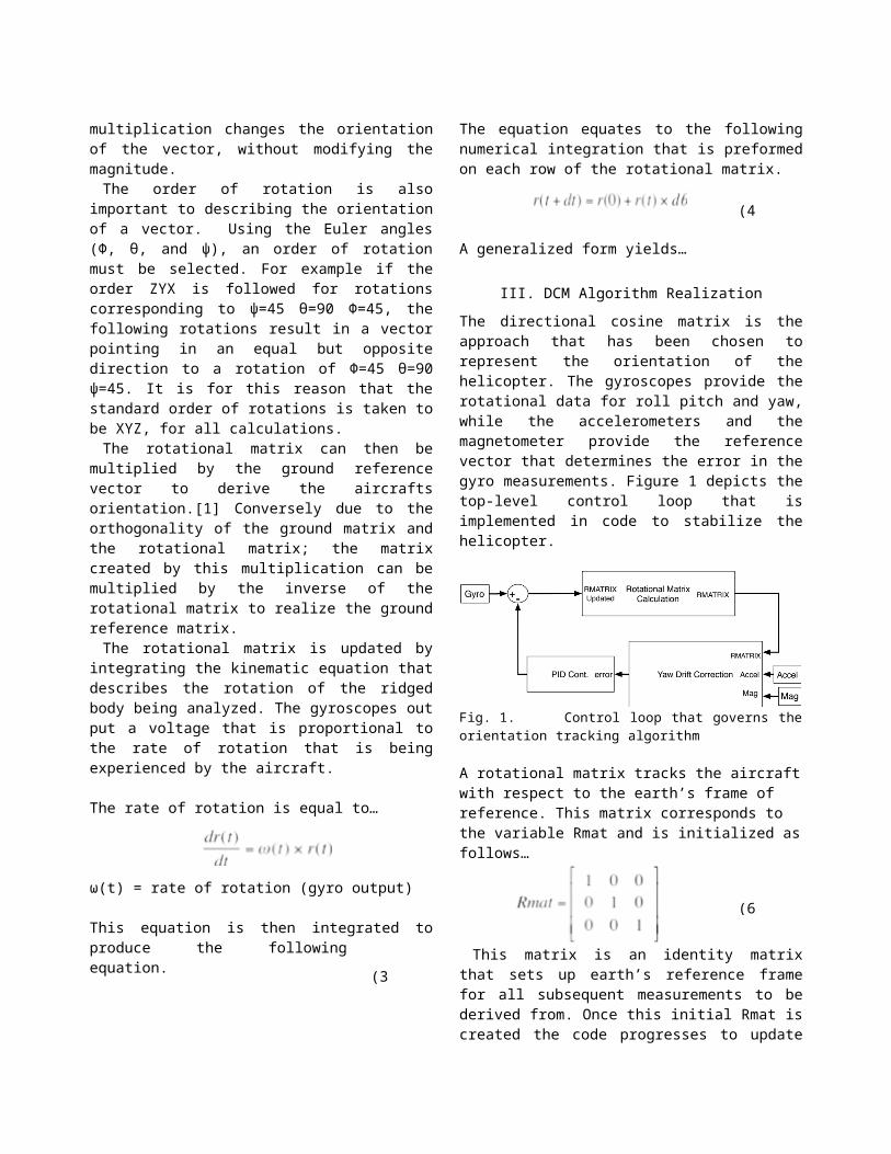
The directional cosine matrix is the approach that has been chosen to represent the orientation of the helicopter. The gyroscopes provide the rotational data for roll pitch and yaw, while the accelerometers and the magnetometer provide the reference vector that determines the error in the gyro measurements. Figure 1 depicts the top-level control loop that is implemented in code to stabilize the helicopter.
Fig. 1. Control loop that governs the orientation tracking algorithm
A rotational matrix tracks the aircraft with respect to the earth’s frame of reference. This matrix corresponds to the variable Rmat and is initialized as follows…
This matrix is an identity matrix that sets up earth’s reference frame for all subsequent measurements to be derived from. Once this initial Rmat is created the code progresses to update Rmat to the orientation information derived from the accelerometer and the magnetometer. This updated Rmat is the aircrafts initial heading while on the ground. Each subsequent iteration of the rotational matrix update is set equal to RmatOld, which provides a
(2)
(5)
(3)
(6)
(4)
reference to derive the rotational angles from the gyro measurements.
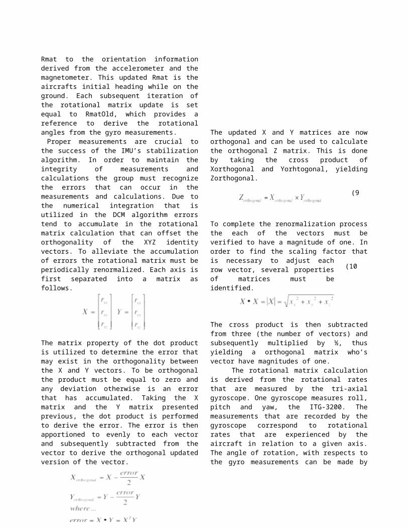
Proper measurements are crucial to the success of the IMU’s stabilization algorithm. In order to maintain the integrity of measurements and calculations the group must recognize the errors that can occur in the measurements and calculations. Due to the numerical integration that is utilized in the DCM algorithm errors tend to accumulate in the rotational matrix calculation that can offset the orthogonality of the XYZ identity vectors. To alleviate the accumulation of errors the rotational matrix must be periodically renormalized. Each axis is first separated into a matrix as follows.
The matrix property of the dot product is utilized to determine the error that may exist in the orthogonality between the X and Y vectors. To be orthogonal the product must be equal to zero and any deviation otherwise is an error that has accumulated. Taking the X matrix and the Y matrix presented previous, the dot product is performed to derive the error. The error is then apportioned to evenly to each vector and subsequently subtracted from the vector to derive the orthogonal updated version of the vector.
The updated X and Y matrices are now orthogonal and can be used to calculate the orthogonal Z matrix. This is done by taking the cross product of Xorthogonal and Yorhtogonal, yielding Zorthogonal.
To complete the renormalization process the each of the vectors must be verified to have a magnitude of one. In order to find the scaling factor that is necessary to adjust each row vector, several properties of matrices must be identified.
The cross product is then subtracted from three (the number of vectors) and subsequently multiplied by ½,
thus yielding a
orthogonal matrix who’s vector have magnitudes of one. The rotational matrix calculation is derived from the rotational rates that are measured by the tri-axial gyroscope. One gyroscope measures roll, pitch and yaw, the ITG-3200. The measurements that are recorded by the gyroscope correspond to rotational rates that are experienced by the aircraft in relation to a given axis. The angle of rotation, with respects to the gyro measurements can be made by relating measurements over a specified time period, T.
This relation is then used to track the change in the aircrafts reference frame in relation to the earth’s by continuously updating the rotational matrix
Proper measurements are crucial to the success of the IMU’s stabilization algorithm. In order to maintain the integrity of measurements and calculations the group must recognize the errors that can occur in the measurements and calculations. Due to the numerical integration that is utilized in the DCM algorithm errors tend to accumulate in the rotational matrix calculation that can offset the orthogonality of the XYZ identity vectors. To alleviate the accumulation of errors the rotational matrix must be periodically renormalized.
The electronic gyroscopes that are being used in this project are susceptible to drift in the measured values. The drift is also compounded by the errors that can accumulate in due to the fact that the numerical integration is approximation, albeit a rather acceptable one. To alleviate the accumulation of errors in the gyro’s measurements and subsequently the rotational matrix the group must perform some sort of drift correction. The chosen method is to utilize a separate reference vector that is determined by alternative measurement technology to the gyroscope. An accelerometer is used to generate a reference measurement to compensate for the roll and pitch drift.
To achieve the correction that is necessary the group realized the properties of the accelerometer. Accelerometers measure gravitation that is experienced by a device plus the acceleration. To create the reference vector we exploit the gravity measurements that are taken by the accelerometer. From these measurements
(11)(7)
(8)
(9)
(10)
(12)
the group can take the cross product with the estimated gyro measurements, the rotational matrix. The cross product of two vectors yields a magnitude that is proportional to the sine of the angle that is formed between the vectors. It also produces a direction that is perpendicular to both vectors.
Equally important to the proper operation of the IMU is the compensation of the yaw drift that can accumulate in the gyro measurements. A magnetometer was chosen as the sensor of choice to generate the yaw reference matrix. In particular a triple axis magnetometer is necessary to be able to correctly derive the matrix. The magnetometer produces a heading measurement that is completely independent of the gyroscope measurements. This measurement is then compared with the rotation experienced by the Z axis of the rotation matrix, thus allowing us to derive the associated error that is present.
A PI controller is responsible incorporating the necessary compensation to correct for the error present between the reference vectors and the rotational matrix’s previous calculation. The Proportional, Integral controller was chosen over the Proportional, Integral and Derivative controller because of the simplicity of code and use of resources on the microcontroller. The derivative term would be much more difficult to implement on the microcontroller, both in use of resources and coding the algorithm. The controller is utilized to minimize the error that is present between the two values. Once the vectors have been sent through the PI controller, they are then fed back to the rotational matrix update algorithm.
Fig. 2. PI controller necessary for mitigating gyro drift
IV. MOTOR CONTROL LOOP
A Proportional Integral Derivative controller is used to compensate the motors to stabilized the aircraft. This is accomplished through pulse width modulation. The rotations per minute are controlled by the pulse width of this signal, ranging from 1ms to 2ms. The PID controller provides the means to update these values to achieve the
desired movements. In addition the PID controller allows for compensation for difference in motors. This attribute is achieved by using the integral term. The integral term accumulates when the aircraft is persistently maintaining a position that is not the desired value. During this condition the pulse width continuously accumulates until the desired value is reached. Equally importaint, especially for quad copters, is the derivative term. The derivative term allows for the quick movements that are necessary to provide timely stabilization.A major component of the PID controller is the associated weights that are necessary to achieve the desired response of the system the corresponding equations for the PID are presented below. We achieve the necessary gains through testing each axis of the aircraft and observing the response of the system for various weights.
V. Microcontroller
The microcontroller is one of the most important components of the quad-copter and there is no way that the quad-copter can even be flown steadily without it. It is responsible for taking in all the data that the other modules output and then processing the data in the DCM algorithm into signals that are then sent into a software PID controller. Some of the signals are used to control the flight characteristics of the quad-copter. The other signals meanwhile are the output information on the status of the quad-copter. It must also complete all the tasks it is required to do in 20 ms for proper motor operation, which means the microcontroller has to be fairly fast. The microcontroller needs 4 ADC channels to convert the accelerometer and ultrasonic rangefinder, it needs to be capable of outputting four PWM signals to control the motors and I2C and UART to communicate with various other modules. The microcontroller that was chosen was the STM32F103CBT6 produced by STMicroelectronics. The STM32 is based on the ARM Cortex-M3 processing core which is a 32-bit architecture microcontroller. The ARM architecture is one of the most used architectures in the mobile device market so there where a lot of resources available to help develop the firmware required for the project. The STM32 variant chosen can run at 72 MHz. The STM32F103CBT6 has two 12-bit ADCs that can convert
(13))
(14)

any of 10 available channels. The STM32 also has 4 16-bit timers that each have 4 output channels. This means that with one timer all 4 motors in the quad-copter can be controlled. The STM32 has 2 USARTs, 2 SPIs, 2 I2C, and a USB as its communication ports. This specific variant of the STM32 also has 128 KB of on board flash memory for storing the quad-copter firmware. There is also 20 KB of on board SRAM to store data into. A great feature that the STM32 has that most microcontrollers do not possess, is its 7 channel DMA. This feature is being used to reduce the amount of processing the STM32 has to do by sending the data from outside modules directly to the embedded memory on the STM32.
VI. Firmware Development
The development board that is being used for this project is the Olimex STM32-H103. The board is very small and has two extension ports on the bottom side to allow access to the STM32 pins. The board uses a JTAG interface located on the top of the board to allow the STM32 to be debugged and programmed. Power is delivered to the board through a USB cable connected between the development board and a PC. The board is very small and has dimensions of 2.4” x 1.3". In order to use the development board a JTAG programmer cable has to be used. The JTAG programmer chosen for the development board was the ARM-USB-TINY which is also made by Olimex Ltd. The JTAG programmer allows the development board to be connected to a computer for programming and debugging. The reason the USB-TINY JTAG programmer was chosen was because it could be connected to a computer via USB port. This feature was needed because the group does not have a computer that has the serial and parallel ports that other JTAG programmers use. The actual firmware was written and compiled with a free development environment supplied by Olimex. It is composed of the Eclipse IDE, GNU C compiler, and OpenOCD. The Eclipse IDE is an open source project manager and is where the C code for the project was written. The GNU C compiler is what converts the C code into instructions that the STM32 can execute. The GNU C compiler is not as efficient in optimizing C code to assembler as the C compilers available on commercial development environments but it has to be used because the commercial compilers have to be licensed, while the GNU C compiler costs nothing to use. The OpenOCD is open source software that is used for two functions. The first function is to write the firmware for the project to the STM32. The other function of the OpenOCD software is to debug the firmware while it is running on the STM32. OpenOCD was used as the firmware writer and debugger because it is the only software of this kind
fully supported by the JTAG programmer. All the individual software parts above are integrated into the Eclipse IDE so all the parts of firmware development are accessed from within Eclipse. The firmware for the STM32 was coded in the C programming language because it is the programming language the group members are most familiar with, it is the programming language used by most ARM Cortex-M3 development tools, and it takes less time to make a program than using assembler. The Eclipse IDE was used to write the source code for the STM32 firmware. The source code written on Eclipse was then compiled by the GNU C compiler. Then OpenOCD was used to allow communication between the development board and the computer through the JTAG programmer and is what writes the firmware onto the STM32 flash memory and allows the communication required for the firmware to be debugged while running on the development board. STMicroelectronics has created a C library that is freely available that makes configuration of the STM32 simpler. This library is called the STM32 standard peripheral library and is intended to cut development time. The standard peripheral library cuts the development time of the firmware because the library provides all the functions, structures, and prototypes necessary to initialize and command any peripheral on the STM32, so that the functionality of this library did not have to be developed by the group. Since the group is composed of novices when it comes to programming for microcontrollers, other people’s source code was examined to help with the writing of the subroutines for several components of the quad-copter firmware. The STM32 standard peripheral library was used to aid in the writing of the subroutines that initialize and control the STM32 and its peripherals. The library documentation provided the instructions of how to use the various library files to setup the various peripherals and features on the STM32. The only problem with this library is that the documentation is not as thorough as it can be causing issues like confusing definitions of functions and variables and trouble finding out what arguments need to be passed into the various functions. If the library was not used as an aid in programming, the programmer would then have to setup the STM32 by knowing the memory address of the various peripheral configuration and data registers and set the corresponding option bits in them. This method is very tedious and can take months to complete because the programmer has to keep searching through the STM32 reference manual for things like the memory addresses of the various registers and which bits in the registers configure the feature that is needed. Then which bits in the registers control which functions have to be looked up and finally, what the bits have to be set to also has to be looked up.

VII. CONTROL BOARD
For the design of the control board the idea was to place the STM32 and IMU components toward the middle of the top layer of the control board PCB, all connectors and switches were placed toward the out side portion of the control board, and all the small simple components like capacitors and LEDs were placed in between. For the components that connect to the control board like the motor ESC’s and the wi-fi, connectors placed on the outside perimeter of the control board were used. Any small component that is difficult to place and route on the top layer was moved to the bottom layer. The empty areas of the bottom layer were covered with a ground plane to provide easy access for the ground pins of all the ICs through vias. The board is powered by two 3.3V regulators, one for digital components the other for analog ones. The ground plane is divided into two areas one is for digital components and the other for analog in order to reduce noise. The connector for the control board power source is in the middle of a side of the control board. A pull switch is used to power the control board on or off. The pull switch is placed somewhere on the control board where it does not interfere with other components and is easily accessible by hand. An LED was placed on the control board that will light up when the board is powered. A 20-pin ribbon cable connector was placed on the control board for a JTAG interface so that the STM32 on the control board can be programmed and tested. The control board was designed in Eagle and manufactured at a group member’s employer Intersil to save on costs.
VIII. Vehicle Body Design
The quad-copter prototype is a lightweight design of less than 900 grams. By reducing the weight, the size of the motors needed to lift the craft is reduced. Thus, less power is consumed by the smaller motors and the flight time of the aircraft increases.
The central part of the body consists of four circular aluminum tubes held together at 90 degree angles by a polyvinyl chloride (PVC) four-way connector and fastened using #4 1 and ½ inch bolts. Four plastic legs are attached to the ends of the arms to form the landing base. The printed control board (PCB) is mounted directly onto the frame by bolting the board legs to the arms on one side and the board on the other. The motors are mounted onto a “C” shaped bracket using #0 ¼ inch bolts and the brackets are in turn bolted to the arms with the #4 bolts. The motor is positioned on the arm such that the propellers do not extend past the end of the arm to protect from potential damage to people or the equipment. The electronic speed controllers (ESCs) are
connected to the motors using standard male to female bullet connectors and 18 gauge wires. The ESCs and wires are placed inside the respective arm tubing and exit the PVC connector through a hole drilled in the center, directly underneath the PCB. Three brackets and two strips of hook and loop fasteners are underneath the PVC connector and serve to hold the larger battery in place. The smaller battery is attached with hook and loop fasteners to the bottom of larger battery. The completed quad-copter is 25 inches in width, 25 inches in length and 5 inches in height. A list of parts with the associated weights is given in table 1.
The lightweight aluminum tubes are chosen for the vehicle chassis because of the great strength to weight ratio. Aluminum has a tensile strength of 600 MPa while maintaining a low density of 2700 kg/m3. The plus shape of the body provides stability as well as increasing the ease of navigation. Each pair of arms corresponds to an axis on the inertial measurement unit (IMU). The batteries are placed under the center of the chassis to keep a low center of gravity and maintain uniform weight across the copter to promote stability. The motors are placed equidistant from the center at a distance that promotes fast system response while remaining stable. This distance was found through trial and error. The ESCs and wires run through the tubes to prevent damage in the case of a crash.
IX. Motor Selection and Design
By keeping the weight to a minimum, the size of the motors needed to lift the craft is reduced. The motors selected for the project are 1300 kv brushless outrunners made by Hextronik. The motors are more efficient than
TABLE IComponent Weights
Item Weight (g)PVC Connector 22Tubular Arm 35#4 Bolt and Nut 5 (x12)#0 Bolt and Nut 1 (x8)Landing Base Leg 8.5 (x4)Bracket 10 (x6)Motor 24 (x4)Propeller 8 (x4)ESC 10 (x4)Bullet Connector 0.8 (x20)PCB 40Large Battery 322Small Battery 35Wire 5 (x10)Total 852

brushed motors, but require a constant signal from the ESCs and are more expensive to purchase. They are also less likely to be damaged in the event of a crash as outrunner motors have the rotor on the outside of the windings. The motors provide up to 400 grams of thrust each at maximum speed with propellers 8 inches in diameter and a 3.8 inch slow flyer pitch. Maximum current draw for each motor with the above mentioned load is near 7.5 amps. The propeller size was chosen specifically because experimental data revealed them to produce the most thrust for the current levels desired by the group. Regular propellers are placed on one axis, and counter-rotating propellers are used on the other axis to counteract the angular momentum of each with the other. The ESCs for the motors are rated up to 10 amps and control the amount of current delivered to the motors. They also are used to change the direction of motion of the motors so that the propellers rotate in the correct direction. The ESCs allow current to flow based on the signal received from the microcontroller. Each speed controller receives a 50 Hz signal with a pulse lasting anywhere from 1 to 2 milliseconds. The pulse width modulated signal (PWM) conveys full throttle when at 2 ms and decreases to no throttle at 1 ms. The control loop adjusts the duty cycle for each ESC throughout the flight of the quad-copter to ensure a stable flight.
X. Power Selection and Design
The quad-copter is powered by two lithium polymer batteries. The larger of the two is a 4400 mAh 11.1V battery that is used to power the motors, ESCs, and battery sensor. Due to the large current draw from the motors, the larger battery is the limiting factor for the flight time of the aircraft. The battery lasts approximately 8 minutes when the motors are at full
throttle and under load. The battery sensor alerts the user that the motors are about to lose power and helps ensure the battery is not drained below the minimum 3 volts required to maintain the battery’s integrity. The smaller battery is a 610 mAh 7.4V battery that powers all the components of the control board. Current draw for the components is listed in table 2. Both batteries are charged fully before extensive flights to minimize problems caused by power loss.
All components on the board use 3.3V; thus, the PCB is equipped with two TLV1117-33 linear voltage regulators. One regulator provides power to the analog side of the microcontroller and the completely analog accelerometer, while the other regulator provides the power for the digital part of the microcontroller and the totally digital magnetometer and gyroscope. The ground planes are also separate for the digital and analog portions of the system. The separation of the digital and analog portions decreases the potential noise that can otherwise interfere between the two types of devices. The two batteries are used for the similar reason of avoiding noise among components, but also to avoid the excess heat and power loss of dropping the 11.1V battery down to 3.3V.
Lithium polymer batteries are used due to their high energy density of approximately 90 to 120 Wh/kg and fast charge times [3]. Disadvantages present themselves in the form of high cost and potential danger of combustion. The batteries comprise almost half of the weight of the quad-copter, and it is therefore important to keep the batteries very close to the center of the vehicle.
XI. iPhone Controller
The application on the IPhone is the main control method to control the quad-copter. The IPhone app has two main screens, one controls the copter and the other give details of the current status of the quad-copter. The sliders on the left and right hand side of the screen tells the control the copters left, right, forward and backward movements. The slider on the bottom of the screen controls the height of copter. These messages are sent over an 802.11G protocol from the IPhone on over the Transceiver that is on the quad-copter. The messages for the left and right sliders had a default format of XX.XX where each “X” represents a value from 0 to 9 and had a max value of 99.99.
To control the height of the copter there is a slider on the bottom of the screen that adjusts the height to the user’s specification. Unlike the sliders that control the side to side and forwards and backwards movement, this slider will not move back to a central position. Instead this slider will stay wherever the user has last moved the
TABLE IICurrent Consumption
Part Current from 4400 mAh Li-Po
Current from 610 mAh Li-Po
Hextronik Motor 7.5 A (x4) 0ESC 2.4 mA (x4) 0Battery Monitor 3 mA 0Cortex M3 Processor
0 36 mA
Wi-Fi Transceiver 0 180 mAUltrasonic Sensor 0 2.1 mAIDG500 0 7 mAADXL335 0 350 uAHMC5843 0 9 mA3.3V Regulator 0 150 mATotal 30.0126 A 384.45 mA
slider to. Upon start up of the copter, the copter will move to a height of 5ft and the slider will accurately portray this as the copter begins to rise. The quad-copter has a safety feature in it to not allow the user to bring it all the way too close to the ground by use of the slider. To monitor the height of the quad-copter we use an ultrasonic sensor that monitors the height. The maximum height for the copter to accurately fly within control of the ultrasonic sensor is of 10 feet. This slider also has a default format of XX.XX which would give the user too precise of a control that would not be useful for the quad-copter. To give it a better feel for the height slider, the group divides the slider level by 5 giving 20 equal levels of unit to use to control the height. Each level represents a half of foot giving a range from 6 inches all the way up to 10 feet.
The packets that are sent to the quad-copter from the IPhone are strings that have 3 characters. The packets have one of three different leading characters either “L”,
“R”, or “H” representing which slider was moved and by how much. The characters following one of those characters will be a number from -10 to 10, besides the bottom the slider which is
from 0 to 20.
BIOGRAPHY
Angel Rodriguez is a graduating senior in the Electrical Engineering degree
program at UCF. His current area of interest and responsibilities in the project involved microcontroller development. After graduation Angel will be seeking employment in the engineering industry.
Daniel Goodhew is a senior student of the electrical engineering department at the University of Central
Florida. He is currently working at Intersil as an applications engineer intern and plans to continue working at Intersil full time in January 2011.
John Sullivan is currently a graduating senior in Computer Engineering at the University of Central Florida. He is interested in applications programing and plans to pursue a job in industry upon graduation.
Jared Rought is currently a senior at the University of Central Florida and will graduate in December 2010 with his Bachelor’s of Science in Electrical Engineering. He currently holds an internship at Lockheed Martin Missiles and Fire Control as an Electrical Engineering Intern. Upon graduation he plans to continue his studies by pursuing a Masters of Science in Electrical Engineering with a concentration in Micro-Systems and Nano-Systems.
Acknowledgement
The authors wish to acknowledge the assistance and support of Dr. Richie, Intersil, the group’s significant others’, and fellow students.
References
[1] Premerlani, William, and Paul Bizard. Directional Cosine Matrix IMU: Theory. Tech. DIY Drone, 17 May 2009. Web. 15 June 2010. <http://diydrones.com/profiles/blogs/dcm-imu-theory-first-draft?id=705844%3ABlogPost%3A77893&page=6#comments>.
[2] "Direction Cosine Matrix." PlanetPhysics. 25 Aug. 2005. Web. 15 June 2010. <http://planetphysics.org/encyclopedia/DirectionCosineMatrix.html>.
[3] Buchmann, Isidor. "What's the Best Battery?" Welcome to Battery University. Cadex, Nov. 2006. Web. July-Aug. 2010. <http://www.batteryuniversity.com/partone-3.htm>.