Embed Size (px)
Citation preview

Submission
doc.: IEEE 802.11-15/1083r0
Cost/Benefit Analysis of SR Techniques
September, 2015
Chuck LukaszewskiAruba Networks, an HP Company
Slide 1
Date: 2015-09-13
Name Affiliations Address Phone email Chuck Lukaszewski Aruba Networks 1344 Crossman
Avenue Sunnyvale, CA, 94089 USA
408.393.1900 [email protected]
Liang Li
Authors:

Submission
doc.: IEEE 802.11-15/1083r0
Chuck Lukaszewski Aruba Networks, an HP Company
Abstract• Significant time in TGax and SGhew has been devoted to three SR
techniques (CCAT / RX sensitivity adjustment, BSS coloring & TPC) but we are having trouble converging on any decision.
• Our indecisiveness may be due in part to a lack of a common view of how to leverage these features, their benefits and their limitations.
• To help break the logjam, we propose a conceptual model of cell structure with “payoff regions” to better apply a cost/benefit analysis.
• We summarize the specific goals, strengths and weaknesses of each SR technique, and offer a cost/benefit analysis at a system level, for the purpose of flushing out disagreements and driving consensus.
• This contribution proposes specific applications of specific SR techniques based on the structural analysis in [1] and attempt to put them into a holistic, cohesive, complementary framework.
• We offer a critical assessment of problems with the DSC proposal, and ideas for mitigating.
September, 2015
Slide 2

Submission
doc.: IEEE 802.11-15/1083r0
PART 1:PROPOSED “PAYOFF REGION” MODEL OF CELL STRUCTURE
September, 2015
Chuck LukaszewskiAruba Networks, an HP Company
Slide 3
Submission
doc.: IEEE 802.11-15/1083r0
Cost/Benefit Evaluation Framework for SR
• A cost/benefit analysis of SR techniques requires a clear definition of the breakeven point.
• In addition, certain SR techniques have useful benefits even when SR is not being attempted. We require a common cell model to evaluate these.
• In [1], we modeled the interference-limited structure of an SR-BSS during simultaneous TX, with a focus on the “rate radius limit” of specific data rates. That approach is a good framework.
September, 2015
Chuck LukaszewskiAruba Networks, an HP Company
Slide 4

Submission
doc.: IEEE 802.11-15/1083r0
SR Payoff Region and Breakeven Point
• The MCS4 rate limit during SR operation is the SR breakeven point.• For any MCS8-limited channelization, this is 50% of MCS8
• For all MCS9 channelizations, it is only 45% of MCS9 (below breakeven)
• Below MCS4, it is always better to defer (no payoff).
• SR should only be attempted for MCS4 and up.
• How do the AP/STA know they are inside this limit? (harder than it looks)
September, 2015
Chuck LukaszewskiAruba Networks, an HP Company
Slide 5
Ch X
MCS4 Limit MCS0 Limit
Ch Y Ch Z Ch X
SR “Payoff” Region
SR “Payoff” Region
SR “Out of the Money” Region
SR C
ase

Submission
doc.: IEEE 802.11-15/1083r0
Payoff Regions – Non-SR Case
September, 2015
Chuck LukaszewskiAruba Networks, an HP Company
Slide 6
SR “Payoff” Region
Deferral “Payoff”Region
“Tail Clip” PayoffRegion
Non
-SR
Cas
e
MCS4Limit
MCS0Limit
• If SR is not being attempted then “classic” cell structure applies.
• Everything outside the SR payoff region is the “deferral payoff region” unless tail clipping is being attempted.
• The “ignore region” exists if the RXS threshold is set to a medium-low value to block distant traffic (more than 3-4 “hops” from MyBSS).
• Tail clipping may occasionally cause SR, but that is not the primary purpose.
RoamThreshold
RXSLimit
-70 to -80 dBm -90 dBm
-82 dBm

Submission
doc.: IEEE 802.11-15/1083r0
PART 2:SR TECHNIQUE INVENTORY & COST/BENEFIT ANALYSIS
September, 2015
Chuck LukaszewskiAruba Networks, an HP Company
Slide 7

Submission
doc.: IEEE 802.11-15/1083r0
Summary of Spatial Reuse Techniques Considered in TGax So Far
September, 2015
Chuck LukaszewskiAruba Networks, an HP Company
Slide 8
Technique DefinitionMajor
VariantsHow Threshold
ChosenApplied
at
RX Sensitivity Tuning
Use artificially-high RXS setting ( > -82 dBm) to convert OBSS frames into noise, increasing CCA idle frequency. (a.k.a. “earmuffs”, CCA Tuning)
StaticOperator selected (how?)
AP
Dynamic (DSC)
AP_RSSI – Constant Margin
STA
BSS Coloring
Use BSS identifier early in frame (e.g. SIG field) to allow receiver to determine MyBSS, and reset CCA to idle if not.
RX-Only vs.
RX+TX
Threshold optional; operator selected if used
All nodes
TPCReduction of EIRP to reduce interference radius Dynamic
Unclear. Presumably MCS maximizing.
All nodes
But how are they to be applied? In what use cases? Where in the cell? Are they mutually exclusive?

Submission
doc.: IEEE 802.11-15/1083r0
RXS Tuning – Summary
September, 2015
Chuck LukaszewskiAruba Networks, an HP Company
Slide 9
Objectives Mechanism(s) Issues
Increase total area throughput via SR (both RX and TX)
• Use high RXS threshold for preamble+NAV avoidance
• Increase TX/RX airtime / decrease channel busy
• Relatively small payoff region [1]• Requirement for “guard cells” [1]• May be incompatible with wide channels [1]• How to choose RXS level on AP/STA? • Competes with BSS coloring for SR• Roaming impacts due to hard edge [2]• Legacy impacts due to hard edge [3-6]
Protect AP CPU in high density / dirty RF environments • “Tail clipping” – use
medium-low RXS threshold to reduce OBSS RX load
• Guard zone and channel width limits may be improved but likely not eliminated
• How to choose RXS level on AP/STA?• Roaming impacts• Legacy impacts • Quantifying possible energy savings at STAs
Improve centralized algorithms by simplifying table sizes (e.g. RRM, roam candidates, etc.)
Reduce “near/far” backoff impact from OBSS RX
• Avoid unnecessary backoff from CRC errors • Need data on how prevalent this really is
Energy savings
• Minimize unnecessary collision backoff/EIFS
• Less time TX, more time sleeping
• STA savings likely limited to arbitration periods (STA is asleep otherwise)
• AP savings likely limited to avoiding control / mgmt TX to distant STAs
Denser use of wider channels • Increase peak burst rate • Wide channels may be incompatible with SR without mitigation features [1]

Submission
doc.: IEEE 802.11-15/1083r0
Problem Statement – Tail Clipping
• The 802.11 PD threshold was selected at a time of sparse “coverage” deployments dominated by low-rate (e.g. BPSK) cell edges.
• Modern enterprise facilities and public venues are engineered for high-rate (e.g. MCS7) cell edges with typical inter-AP distances of ~20m.
• Radio sensitivity has improved dramatically since Clause 17 was first ratified. Typical RXS levels for BPSK are now < -90 dBm.
• Due to 30 dB / 1000X power delta from PD to ED, both APs and STAs defer to very low-power sources many “hops” away.
• Extra low-SINR control and data traffic stresses APs, STAs and distribution system equipment unnecessarily.
• Neither APs nor STAs are designed to handle large BSS table sizes. Large tables lead to poor STA roaming decisions, difficult RRM logic, among other issues. Shrinking tables speeds compute, reduces CPU energy use, and improves accuracy.
September, 2015
Chuck LukaszewskiAruba Networks, an HP Company
Slide 10
Submission
doc.: IEEE 802.11-15/1083r0
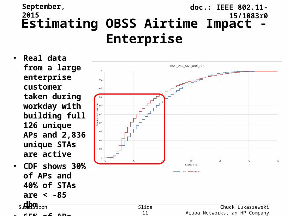
Estimating OBSS Airtime Impact - Enterprise
• Real data from a large enterprise customer taken during workday with building full 126 unique APs and 2,836 unique STAs are active
• CDF shows 30% of APs and 40% of STAs are < -85 dbm.
• 65% of APs and 75% of STAs are < -75 dBm.
September, 2015
Chuck LukaszewskiAruba Networks, an HP Company
Slide 11

Submission
doc.: IEEE 802.11-15/1083r0
Estimating OBSS Impact – Enterprise (STAs)
• Data from 10 most heavily-loaded APs at customer site
• Charts show RSSI & SINR for all STAs that are audible from each of the 10 APs (regardless of association).
• RSSI chart on left shows 150-300 STAs at < -75 dBm
September, 2015
Chuck LukaszewskiAruba Networks, an HP Company
Slide 12

Submission
doc.: IEEE 802.11-15/1083r0
Estimating OBSS Impact – Enterprise (APs)
• Data from 10 most heavily-loaded APs at customer site
• Charts show SINR & RSSI for all OBSS APs that are audible from each of the 10 APs.
• RSSI chart on left shows 65-120 OBSS APs at < -75 dBm
September, 2015
Chuck LukaszewskiAruba Networks, an HP Company
Slide 13

Submission
doc.: IEEE 802.11-15/1083r0
Slide 14 Chuck LukaszewskiAruba Networks, an HP Company
Estimating OBSS Impact – Stadium 5-GHz
• Data from 10 most heavily-loaded 5-GHz radios at 70K seat stadium
• There are 254 APs with 3,748 unique associated STAs on 5-GHz.
• Charts show SINR for all APs (left) and STAs (right) that are audible from each of the APs (regardless of association).
• AP chart on left shows up to 100 APs at < 10 dB
• STA chart on right shows > 250 STAs each at <10 dB
• Reinforces need for large BSS color field (minimum 8 bits)
September, 2015

Submission
doc.: IEEE 802.11-15/1083r0
Estimating OBSS Impact – Stadium 2.4-GHz
September, 2015
Chuck LukaszewskiAruba Networks, an HP Company
Slide 15
• Data from 10 most heavily-loaded 2.4-GHz radios at 70K seat stadium
• There are 254 APs with 3,201 unique associated STAs on 2.4-GHz.
• AP chart on left shows up to 100 APs at < 10 dB
• STA chart on right shows higher SINRs than 5-GHz, tail clipping would require higher threshold.

Submission
doc.: IEEE 802.11-15/1083r0
Benefit Statement – Tail Clipping• Tail clipping is the blocking of low-RSSI OBSS signals for reasons other than
spatial reuse.
• A tail-clipping enabled BSS would advertise that fact, along with an operator-selected or AP-determined threshold:• Value could not be higher than -75 dBm to avoid conflict with roaming thresholds and to
ensure the entire MyBSS is cleared.
• Value could not be lower than about -85 dBm or there would be no value.
• -82 dBm might be an excellent common value, thereby restoring original intent of 802.11.
• The following benefits could be realized:• Protect AP CPU in high density / dirty RF environments
• Reduce “near/far” backoff impact from OBSS RX
• Improve both AP and STA algorithm performance and user experience by shrinking tables
• Energy savings
• In addition, unintentional deferral to distant full power LTE-U or LAA eNBs using CTS-to-self could be avoided / “protected”.
September, 2015
Chuck LukaszewskiAruba Networks, an HP Company
Slide 16

Submission
doc.: IEEE 802.11-15/1083r0
Benefit Statement – Energy Savings
• Battery-powered nodes (APs or STAs)• STAs:
• Reduction of arbitrations aborted due to low-RSSI OBSS devices• Could reduce attempts for RTS, NDP with PM=0/1, probing
• Ability to clear TX buffers faster and get back to sleep sooner
• Reduced CPU compute energy to run certain algorithms
• APs: • Avoid responding to management frames from distant STAs
• Some APs are already battery- or solar-powered today. In the future, low-power/industrial/IoT/embedded scenarios could make AP energy consumption savings important.
• Powered nodes (APs or STAs)• Is there really anything significant enough here to mention?
September, 2015
Chuck LukaszewskiAruba Networks, an HP Company
Slide 17

Submission
doc.: IEEE 802.11-15/1083r0
RXS Tuning – Caveats & Limitations
• Very small payoff region for SR (30-40% of SR-BSS midpoint).• Dumb payoff decisions…
• Requirement for guard zone (2-5 cell diameters) between same-channel SR-BSS. No value at short SR-ICD values without walls/floors/crowd. Better to defer.• Possible incompatibility with bonded channels for same reason.
• No ability to separate TX and RX logic – Effect is completely bidirectional with a “hard edge”.
• Maximum usable RXS limit must be well below typical client roaming thresholds (-70 dBm - 6 dB margin) unless clients agree to modify their roaming algorithms in SR-ESS. How to negotiate?
• Roaming algorithm redesign to handle rapid rolloff, PER superseding RSSI, and improved AP coordination.
• Legacy STA fairness issues
• How exactly to choose the correct RXS level / margin?
September, 2015
Chuck LukaszewskiAruba Networks, an HP Company
Slide 18

Submission
doc.: IEEE 802.11-15/1083r0
BSS Coloring – Summary
September, 2015
Chuck LukaszewskiAruba Networks, an HP Company
Slide 19
Objectives Mechanism(s) Issues
Increase total area RX throughput via SR • Use BSS identifier early
in frame (e.g. SIG field) to allow receiver to determine MyBSS, and reset CCA to idle if not.
• Separate RX/TX decision making.
• Optional protection of legacy STAs and sticky MyBSS STAs on RX
• Intelligent TX SR payoff decisions based on OBSS signal level
• Same issues as RXS tuning regarding small payoff region, guard zone and wide channel restrictions during SR periods.
• However, does not need to suffer from roaming or legacy impacts due to “soft” edge and per-frame decision making.• How to choose secondary signal
threshold for deferring to legacy STAs• Competes with RXS tuning for SR• Size of color field has to be large enough for
very high density deployments (500+ APs per channel)
• Legacy protection on RX should be operator configurable inside managed ESS perimeters
• Need to fire interrupt and process preambles for very low-RSSI OBSS frames
Increase total area TX throughput via SR
Energy savings
• Minimize unnecessary collision backoff/EIFS
• Less time TX, more time sleeping
• STA savings likely limited to arbitration periods (STA is asleep otherwise)
• AP savings likely limited to avoiding control / mgmt TX to distant STAs
Denser use of wider channels • Increase peak burst rate • Wide channels may be incompatible with SR without mitigation features [1]

Submission
doc.: IEEE 802.11-15/1083r0
Chuck Lukaszewski Aruba Networks, an HP Company
Color Field – Minimum Size Requirement
• Color field must scale to size of modern ESS.• Technique is especially needed in very high density use cases in open
areas, like airports and stadiums.
• Large stadiums (80K – 100K seats) commonly have 1,200 – 2,000 total APs with 2-4 virtual APs each.
• For 2.4-GHz, this means 400-700 APs per channel and 800 – 2,800 BSSIDs per channel.
• Things are better in 5-GHz, but this still means 60 – 100 APs per channel with 120 – 400 BSSIDs each.
• Assume that color field is unique per channel (but same ESS can re-use entire color space on each channel).
• Assume that all BSS must have unique color, whether they can hear one another or not.
• For multiple-operator overlays (e.g. Thailand malls) how to avoid color collision? Or 1000s of residential networks embedded inside outdoor cable/hotspot network. PLMN ID plus color? PAID? [7]
September, 2015
Slide 20
Submission
doc.: IEEE 802.11-15/1083r0
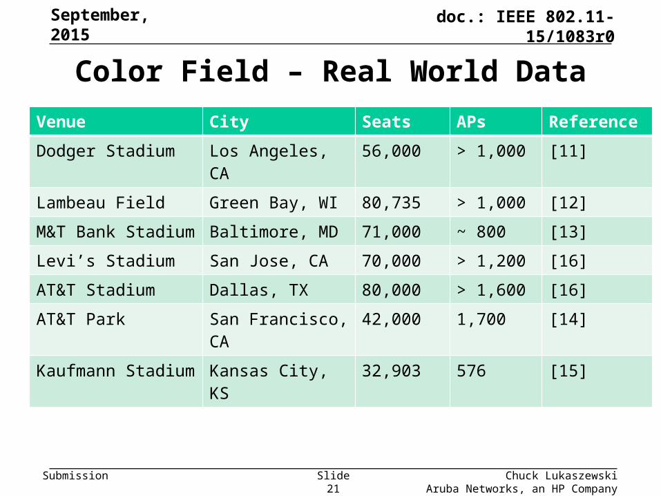
Color Field – Real World Data
Venue City Seats APs Reference
Dodger Stadium Los Angeles, CA 56,000 > 1,000 [11]
Lambeau Field Green Bay, WI 80,735 > 1,000 [12]
M&T Bank Stadium Baltimore, MD 71,000 ~ 800 [13]
Levi’s Stadium San Jose, CA 70,000 > 1,200 [16]
AT&T Stadium Dallas, TX 80,000 > 1,600 [16]
AT&T Park San Francisco, CA 42,000 1,700 [14]
Kaufmann Stadium Kansas City, KS 32,903 576 [15]
September, 2015
Chuck LukaszewskiAruba Networks, an HP Company
Slide 21

Submission
doc.: IEEE 802.11-15/1083r0
Transmit Power Control – Summary
September, 2015
Chuck LukaszewskiAruba Networks, an HP Company
Slide 22
Objectives Mechanism(s) Issues
Increase total area throughput via SR (both RX and TX)
• Reduce interference to OBSS by reducing EIRP to minimum required to achieve maximum data rates to peer within MyBSS.
• Increase TX/RX airtime / decrease channel busy
• Longer list of key issues on next slide.
• Same issues as RXS tuning regarding small payoff region, guard zone and wide channel restrictions during SR periods.
• How to choose optimal EIRP level on AP/STA?
Energy savings
• Reduce energy used to TX frames by reducing EIRP
• Minimize unnecessary collision backoff/EIFS
• Less time TX, more time sleeping
• STA savings likely limited to arbitration periods (STA is asleep otherwise)
• AP savings likely limited to avoiding control / mgmt TX to distant STAs

Submission
doc.: IEEE 802.11-15/1083r0
Chuck Lukaszewski Aruba Networks, an HP Company
Why TPC Doesn’t Work
• TPC by itself does not really help us• Only works at very large SR-ICD scales / or NLOS high-shadowing.
• Must reduce OBSS < PD detect level to help. This is a long way (< -90 dBm!)
• Gain can be neutralized by any 3rd party same-channel BSS overlay
• TPC requires variable power reduction (separate values for preamble & payload) ( laurant)
• TPC in combination with Coloring or RXS does not help• Fundamental contradiction – if all APs and STAs reduce EIRP by
same amount then there is no advantage because SR-BSS structure is EIRP-invariant. But if nodes choose different power levels, then weak EIRP nodes are penalized. [1]
• Loss of rate is worse than increase interference radius.
September, 2015
Slide 23

Submission
doc.: IEEE 802.11-15/1083r0
Conclusion – Cooperative SR Framework
September, 2015
Chuck LukaszewskiAruba Networks, an HP Company
Slide 24
“Tail Clip” PayoffRegion
Non
-SR
Cas
e
• RXS and coloring are mutually exclusive here
• Coloring allows separate RX/TX decisions
• Coloring may make smarter per-frame payoff decisions
• RXS must make “blind” payoff decisions
• RXS has hard edge with implicit deferral inside
• Coloring supports soft edge with optional per-frame legacy and sticky client protection
• RXS/DSC is not viable because max usable threshold = ~ -76 dBm.
• RXS with low threshold (-76 to -80 dBm) works well
• Provides CPU protection and improves algorithm quality
• Restores the “-82” style intent to interference range
• Can default off unless operators enable.
SR “Payoff” Region
Deferral “Payoff”Region
BSS COLORING RXS TUNING

Submission
doc.: IEEE 802.11-15/1083r0
Key Issues / Unknowns
• How much efficiency hit does coloring suffer relative to RXS due to preamble processing?
• Could RXS be made to make “smart” payoff decisions by studying instantaneous NF?
• Can STA vendors be convinced to provide adaptive roaming algorithms that would permit higher downlink RXS thresholds? (but then how to solve for legacy?)
September, 2015
Chuck LukaszewskiAruba Networks, an HP Company
Slide 25

Submission
doc.: IEEE 802.11-15/1083r0
PART 3:RE-ENGINEERING DSC
September, 2015
Chuck LukaszewskiAruba Networks, an HP Company
Slide 26

Submission
doc.: IEEE 802.11-15/1083r0
Challenges with Current DSC Proposal
• Bidirectional margin: Uplink margin must equal downlink margin
• How to choose margin: No algorithm proposals have been contributed.
• Designed for short range: High DSC uplink margin values negate the benefit by rapidly converging DSC-enabled cells to normal CCA • Most DSC contributions have generally used AP-advertised margins >= 20 dB.
[8] [9] [10] [many others…]
• However, this level of margin seriously impairs the potential effectiveness of the technique by converging to standard CCA-PD beyond 20 meters.
• Neither large margins nor advertising are required. Much smaller adaptive values can achieve same goal, or even no margin with RTS/CTS.
• Breaks roaming: High downlink margin breaks roaming if AP CCAT is set higher than mobile device roam thresholds. [2] • Most DSC examples propose combined UL and Margin in -55 to -60 range.
• However, combination of DSC Upper Limit and DSC Margin can never exceed -70 dBm plus a safety margin. Some devices require lower values.
September, 2015
Chuck LukaszewskiAruba Networks, an HP Company
Slide 27

Submission
doc.: IEEE 802.11-15/1083r0
Chuck LukaszewskiAruba Networks, an HP Company
How Uplink Margins Actually Work
• Large downlink margin deducted from measured beacon RSSI converges to standard CCA-SD level at typical -65 dBm cell edge.
• This is just <=20m - so what is the point of going to all the trouble?
September, 2015
Upper Limit -40dBmMargin 20dBAP CCA Threshoild -60dBm
Perfect match if AP CCA is -50dBm
40ft
Simplified Cell Model from 14/0779r2
Diagram is incorrect assumes variable margin
d = 80mRSSI = -78RXS = -98
d = 40mRSSI = -68RXS = -88
Actual SS#3 PL Model w/Static Margin
UL = -48Margin = 20
AP CCA = -68
Submission
doc.: IEEE 802.11-15/1083r0
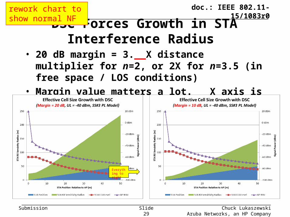
DSC Forces Growth in STA Interference Radius
September, 2015
Chuck LukaszewskiAruba Networks, an HP Company
Slide 29
• 20 dB margin = 3.__X distance multiplier for n=2, or 2X for n=3.5 (in free space / LOS conditions)
• Margin value matters a lot. X axis is not to scale!
Everything to right
rework chart to show normal NF

Submission
doc.: IEEE 802.11-15/1083r0
Result Is By Design – But is it What We Want?
• 14/0779r2 states:• “DSC maintains full sensitivity”
• “The chance of hidden STAs in the home network is greatly reduced”
• “The DSC STA, maintains full range. The sensitivity will move towards lowest value as the STA moves away from the AP.”
• This is the opposite of tail clipping for STAs.
• Is full sensitivity really necessary for SR?
• Increasing prevalence of RTS / CTS for dynamic bandwidth, LTE/LAA clearing, etc. will
• Coloring may be a superior solution for SR that is legacy-compatible.
• This implies that DSC is only targeted to deliver SR at short distances. But there is trouble there…
September, 2015
Chuck LukaszewskiAruba Networks, an HP Company
Slide 30

Submission
doc.: IEEE 802.11-15/1083r0
Downlink Margin: Breaking Roaming
• In 14/1416r1, we reported serious problems with STAs roaming between APs with static AP CCAT set higher than device roaming threshold. (e.g. high downlink margin)• 2 major phone OS and 1 major laptop OS were tested
• AP CCAT level should never be set higher than:
Device_Roam_Threshold – 3dB
• Roam thresholds of major OS range from -70 to -85 dBm.
• Only way to avoid is to make HE clients aware of AP_CCA.• Concurrent SR-BSS transmission breaks RSSI-based roaming
• Advertising key info needed by client to assess position relative to edge
• Graceful negotiation of cell exit
September, 2015
Chuck LukaszewskiAruba Networks, an HP Company
Slide 31

Submission
doc.: IEEE 802.11-15/1083r0
Chuck Lukaszewski, Aruba Networks
Limit for Downlink DSC** Margin
• Roaming threshold must be inside the AP CCAT radius
• But roaming there will fail unless BSS overlap by 2R
• So Upper Limit + downlink margin must be < PRX_Roam
** AP uses static CCA threshold that is derived from DSC margin
November, 2014
Slide 32
Roamthresh
R
CCATmax
R RCh X Ch Y
AP1 AP2

Submission
doc.: IEEE 802.11-15/1083r0
Resolving the Conflict
• Separate the downlink and uplink CCAT levels (margins)
• For downlink:• Flip the model. Employ tail clipping instead of short-range SR.
• Operator chooses DL CCAT based on system design.
• HE STAs could implement adaptive roaming algorithms using cell configuration signaled by AP, and perhaps negotiated entry/exit
• For uplink, potential solutions include:• Use smaller, smarter uplink margins!
• Leverage RTS/CTS for MyBSS clearing
• If no RTS/CTS, then
• Situation varies depending on whether another SR-BSS is TXing simultaneously (e.g. normal vs. compressed SINR)
September, 2015
Chuck LukaszewskiAruba Networks, an HP Company
Slide 33

Submission
doc.: IEEE 802.11-15/1083r0
-7880-98
Uplink CCAT: What Margin with RTS/CTS?
• For RTS/CTS case, there are 2 methods: Fixed & variable
• STA just has to reach AP. Could combine with uplink TPC.
September, 2015
Chuck LukaszewskiAruba Networks, an HP Company
Slide 34
Method #1 – FixedMatch Advertised AP CCAT
Method #2 – VariableAP-RSSI – Safety margin (3-6dB)
APAPSTA should
never get here

Submission
doc.: IEEE 802.11-15/1083r0
Uplink CCAT: What Margin Without RTS/CTS?
• No RTS/CTS is much more complicated.
• Must clear entire cell.
• Even if STA has estimate of n and knowledge of AP CCAT, no reliable way to estimate required CCA level.
• Options are:• Use default CCAT
• Use CTS-2-self @ full EIRP
• AP advertises estimated n and STA calculates CCAT
September, 2015
Chuck LukaszewskiAruba Networks, an HP Company
Slide 35
Submission
doc.: IEEE 802.11-15/1083r0
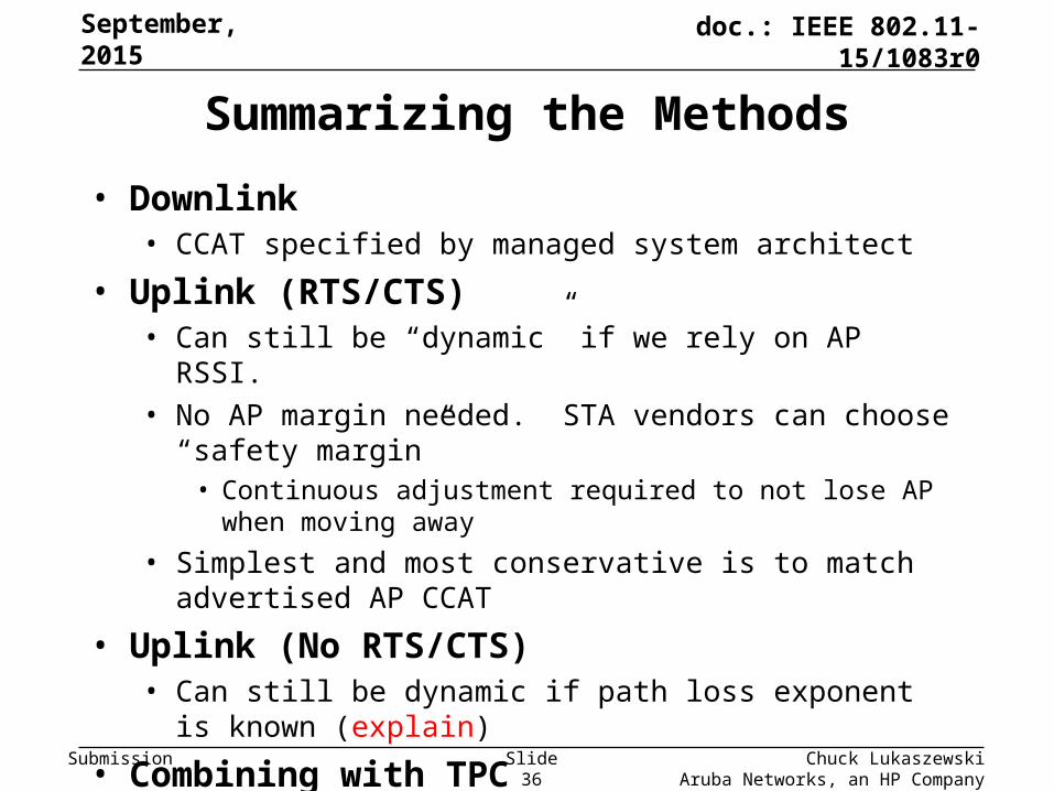
Summarizing the Methods
• Downlink• CCAT specified by managed system architect
• Uplink (RTS/CTS)• Can still be “dynamic” if we rely on AP RSSI.
• No AP margin needed. STA vendors can choose “safety margin”• Continuous adjustment required to not lose AP when moving away
• Simplest and most conservative is to match advertised AP CCAT
• Uplink (No RTS/CTS)• Can still be dynamic if path loss exponent is known (explain)
• Combining with TPC• Accurate per-frame TX power control also requires accurate
estimate of n.
September, 2015
Chuck LukaszewskiAruba Networks, an HP Company
Slide 36

Submission
doc.: IEEE 802.11-15/1083r0
Chuck Lukaszewski Aruba Networks, an HP Company
References1. 15/1082r0 – “Analysis of BSS and ESS Structure During Concurrent SR
Transmissions”, C Lukaszewski (Aruba), Sep 2015
2. 14/1416r1 – “Observed protocol violations caused by DSC with roaming STAs”, C Lukaszewski (Aruba), Nov 2014
3. 14/1224r0 – “Link-Aware CCA”, B Hart (Cisco), Sep 2014
4. 14/0372r2 – “System Level Simulations on Increased Spatial Reuse”, Jiang et al (Marvell), Mar 2014
5. 14/1207r1 – “OBSS Reuse Mechanism Which Preserves Fairness”, I Jamil, L Cariou (Orange), Sep 2014
6. 14/0854r0 – “DSC and Legacy Coexistence”, W Carney, Y Morioka et al (Sony), Jul 2014
7. 13/1207r1 – “CID 205 BSSID Color Bits”, M. Fischer et. Al, Sep 2013 (11ah)
8. 14/0779r2 - “Dynamic Sensitivity Control - Practical Usage” , Graham Smith, July 2014
9. 14/0328r2 – “ Dense Apartment Complex Throughput Calculations, “ Graham Smith, Mar 2014
10. 14/0045r1 – “E-Education Analysis,” Graham Smith, Jan 2014
September, 2015
Slide 37

Submission
doc.: IEEE 802.11-15/1083r0
References (continued)
11. http://www.mobilesportsreport.com/2015/09/stadium-tech-report-los-angeles-dodgers-hit-it-out-of-the-park-with-cisco-aruba-wi-fi/
12. http://www.mobilesportsreport.com/2015/08/wi-fi-for-the-frozen-tundra-extreme-verizon-bring-wi-fi-to-green-bay-packers-lambeau-field/
13. http://www.mobilesportsreport.com/2015/08/baltimore-ravens-pick-extreme-networks-for-mt-bank-stadium-wi-fi/
14. http://www.mobilesportsreport.com/2015/07/stadium-tech-report-world-series-set-new-wireless-records-at-att-park/
15. http://www.mobilesportsreport.com/2015/06/stadium-tech-report-kauffman-stadium-gets-a-royal-wi-fi-upgrade/
16. http://www.mobilesportsreport.com/2015/01/stadium-tech-report-att-stadiums-massive-antenna-deployment-delivers-solid-wi-fi-das-performance/
September, 2015
Chuck LukaszewskiAruba Networks, an HP Company
Slide 38