Embed Size (px)
Citation preview
REPUBLIC OF SOUTH AFRICAP.O. Box 11325, Selcourt 1567,15 Miller Road,Nuffield, Springs - GautengTel. +27.11.818.5818Fax +27.11.818.3710
Via Brughiera 1 - 20010PREGNANA MILANESE (MI)Tel. +39.02.93.27.111Fax. +39.02.93.27.1154www.pentairwater.com
ITALYVia Masaccio, 1356010 Lugnano (Pisa)Tel. +39.050.71.61.11Fax. +39.050.70.31.37www.nocchi.it
140, avenue Roland Garros78532 BUC CEDEXTel. +33.(0)1.39.24.15.00Fax. +33.(0)1.39.56.03.90www.pentairwater.com
FRANCEBP 92 Vedéne - 84965LE PONTET Cedex - AVIGNONTel. 04.90.480.880Fax 04.90.480.888www.nocchi.it
UNITED ARAB EMIRATESApt. # 404, Al Buhaira Building-Corniche StreetAl Buhaira - Al MajazP.O. Box 32789Sharjah, U.A.E.Tel. +971.65.72.05.52Fax. +971.65.72.05.53www.pentairwater.com
Tel. +49.52.04.17-0
GERMANYJung Pumpen GmbHIndustriestr. 4-6D-33803 Steinhagen
Fax +49.52.04.17-331www.jung-pumpen.de
50 H
zG
B - 1
° ED
. 052
010
- CO
D. N
V260
PH80
Submersible and submerged pumpsDrainage and sewage pumps
BELGIUMIndustriepark Wolfstee,Toekomstlaan 30B-2200 HERENTALSTel. +32.14.25.99.11Fax. +32.14.25.99.75www.pentairwater.com G
B

Technical data subject to change without notice.
PENTAIR WATER ITALY reserves the right to carry out modifications to its products at any time without having to provide prior notice.


4
INDEX
PRATIKA MULTISTAGE CENTRIFUGAL SUBMERSIBLE PUMPS FOR CLEAR WATER 6
DOMINATOR 4 4” MULTISTAGE CENTRIFUGAL SUBMERSIBLE PUMPS COMPLETE WITH MOTOR 8
DOMINATOR 5 SUBMERSIBLE MULTISTAGE CENTRIFUGAL PUMP FOR CLEAR WATER 10
SCM 4 Plus 4” MULTISTAGE CENTRIFUGAL SUBMERSIBLE PUMPS COMPLETE WITH MOTOR 12
SCM 4 HF 400 4” MULTISTAGE CENTRIFUGAL SUBMERSIBLE PUMPS COMPLETE WITH MOTOR 21
SCM 4 Plus / HF PUMP-END
SUBMERSIBLE PUMPS 23
4” MOTORS 4” SUBMERSIBLE MOTORS FOR SCM 4 PLUSNEMA SPEC WITH PART ELECTRICAL CABLE 25
SA 6” MULTISTAGE SUBMERSIBLE PUMPS COMPLETE WITH MOTOR 26
SA PUMP-ENDS 6” SUBMERSIBLE PUMPS 31
6” MOTORS ELECTRIC MOTORS Ø 6” FOR SUBMERSIBLE PUMPS 32
DP SUBMERSIBLE PUMPS FOR DRAINING CLEAR WATER 35
SIMER “SIMO” PUMP SUBMERSIBLE PUMPS FOR DRAINING CLEAR WATER 37
DPC SUBMERSIBLE PUMPS FOR DRAINING CLEAR WATER 39
DRENOX SUBMERSIBLE PUMPS FOR DRAINING CLEAR WATER 41
DPV SUBMERSIBLE PUMP FOR DRAINING DIRTY WATER 44
OMNIA SUBMERSIBLE PUMP FOR DRAINING DIRTY WATER 46
BIOX XS SUBMERSIBLE EFFLUENT VORTEX PUMPS FOR DIRTY WATER 48
PRIOX SUBMERSIBLE EFFLUENT VORTEX PUMPS FOR DIRTY WATER 50
MINIVORT P SUBMERSIBLE EFFLUENT VORTEX PUMPS FOR DIRTY WATER 52
MINIVORT PP SUBMERSIBLE EFFLUENT VORTEX PUMPS FOR DIRTY WATER 54
VACUSYSTEM COLLECTION AND PUMPING STATIONS FOR DIRTY WATER 56
VERSAILLES SUBMERSIBLE PUMPS FOR FOUNTAINS AND WATER FEATURES 62
EXPANSION TANKS IN COMPOSITE MATERIAL 65
EXPANSION TANKS STAINLESS STEEL 66
EXPANSION TANKS PAINTED STEEL 67
FLUSSCONTROL - F. BASIC ELECTRONIC CONTROL AND PROTECTION DEVICE FOR ELECTRIC SINGLE PHASE PUMPS 68
QES PLUS SINGLE PHASE STARTER FOR THE CONTROL AND PROTECTION OF SUBMERGED ELECTRIC PUMPS, DIRECT START 69
AT THREE PHASE ELECTRIC PANEL FOR THE PROTECTION AND CONTROL OF SUBMERSIBLE OR SURFACE ELECTRIC PUMPS, DIRECT START 70
AD THREE PHASE STARTER FOR THE CONTROL OF SUBMERGED OR SURFACE ELECTRIC PUMPS, DIRECT START 71
AY THREE PHASE STARTERS FOR THE CONTROL OF SUBMERGED OR SURFACE ELECTRIC PUMPS 72
ADRM SINGLE PHASE STARTERS FOR THE CONTROL OF ONE OR TWO DRAINING AND SEWAGE ELECTRIC PUMPS 73
ADRD THREE PHASE STARTERS FOR THE CONTROL OF ONE OR TWO DRAINING AND SEWAGE ELECTRIC PUMPS 74
ADRY THREE PHASE STARTERS FOR THE CONTROL OF ONE OR TWO DRAINING AND SEWAGE ELECTRIC PUMPS, STAR-TRIANGLE START 75
Accessories ACCESSORIES FOR CONTROL PANELS 76

5
CONTENTS IN ALPHABETIC ORDER
CO
NTE
NTS IN
ALP
HA
BE
TIC
OR
DE
R
4” MOTORS 4” SUBMERSIBLE MOTORS FOR SCM 4 PLUSNEMA SPEC WITH PART ELECTRICAL CABLE 25
6” MOTORS ELECTRIC MOTORS Ø 6” FOR SUBMERSIBLE PUMPS 32
Accessories ACCESSORIES FOR CONTROL PANELS 76
AD THREE PHASE STARTER FOR THE CONTROL OF SUBMERGED OR SURFACE ELECTRIC PUMPS, DIRECT START 71
ADRD THREE PHASE STARTERS FOR THE CONTROL OF ONE OR TWO DRAINING AND SEWAGE ELECTRIC PUMPS 74
ADRM SINGLE PHASE STARTERS FOR THE CONTROL OF ONE OR TWO DRAINING AND SEWAGE ELECTRIC PUMPS 73
ADRY THREE PHASE STARTERS FOR THE CONTROL OF ONE OR TWO DRAINING AND SEWAGE ELECTRIC PUMPS, STAR-TRIANGLE START 75
AT THREE PHASE ELECTRIC PANEL FOR THE PROTECTION AND CONTROL OF SUBMERSIBLE OR SURFACE ELECTRIC PUMPS, DIRECT START 70
AY THREE PHASE STARTERS FOR THE CONTROL OF SUBMERGED OR SURFACE ELECTRIC PUMPS 72
BIOX XS SUBMERSIBLE EFFLUENT VORTEX PUMPS FOR DIRTY WATER 48
DOMINATOR 4 4” MULTISTAGE CENTRIFUGAL SUBMERSIBLE PUMPS COMPLETE WITH MOTOR 8
DOMINATOR 5 SUBMERSIBLE MULTISTAGE CENTRIFUGAL PUMP FOR CLEAR WATER 10
DP SUBMERSIBLE PUMPS FOR DRAINING CLEAR WATER 35
DPC SUBMERSIBLE PUMPS FOR DRAINING CLEAR WATER 39
DPV SUBMERSIBLE PUMP FOR DRAINING DIRTY WATER 44
DRENOX SUBMERSIBLE PUMPS FOR DRAINING CLEAR WATER 41
EXPANSION TANKS IN COMPOSITE MATERIAL 65
EXPANSION TANKS PAINTED STEEL 66
EXPANSION TANKS STAINLESS STEEL 67
FLUSSCONTROL - F. BASIC ELECTRONIC CONTROL AND PROTECTION DEVICE FOR ELECTRIC SINGLE PHASE PUMPS 68
MINIVORT P SUBMERSIBLE EFFLUENT VORTEX PUMPS FOR DIRTY WATER 52
MINIVORT PP SUBMERSIBLE EFFLUENT VORTEX PUMPS FOR DIRTY WATER 54
OMNIA SUBMERSIBLE PUMP FOR DRAINING DIRTY WATER 46
PRATIKA MULTISTAGE CENTRIFUGAL SUBMERSIBLE PUMPS FOR CLEAR WATER 6
PRIOX SUBMERSIBLE EFFLUENT VORTEX PUMPS FOR DIRTY WATER 50
QES PLUS SINGLE PHASE STARTER FOR THE CONTROL AND PROTECTION OF SUBMERGED ELECTRIC PUMPS, DIRECT START 69
SA 6” MULTISTAGE SUBMERSIBLE PUMPS COMPLETE WITH MOTOR 26
SA PUMP-ENDS 6” SUBMERSIBLE PUMPS 31
SCM 4 HF 400 4” MULTISTAGE CENTRIFUGAL SUBMERSIBLE PUMPS COMPLETE WITH MOTOR 21
SCM 4 Plus 4” MULTISTAGE CENTRIFUGAL SUBMERSIBLE PUMPS COMPLETE WITH MOTOR 12
SCM 4 Plus / HF PUMP-END
SUBMERSIBLE PUMPS 23
SIMER “SIMO” PUMP SUBMERSIBLE PUMPS FOR DRAINING CLEAR WATER 37
VACUSYSTEM COLLECTION AND PUMPING STATIONS FOR DIRTY WATER 56
VERSAILLES SUBMERSIBLE PUMPS FOR FOUNTAINS AND WATER FEATURES 62

6
PRATIKAMULTISTAGE CENTRIFUGAL SUBMERSIBLE PUMPS FOR CLEAR WATER
The PRATIKA submersible pumps are portable and ready to use for installation in traditional wells, water deposits, collection tanks, clear watercourses, lakes etc.Equipped with Ø 32 hose adapter.Automatic version equipped with float switch.
Usage limitations- Type of liquid: clean water with no suspended solids or abrasive material- Maximum liquid temperature 40° C- Maximum submersion under the water level 10 m
Applications- Pumping of water from traditional wells- Domestic tank installations for boosting domestic drinking water systems- Small-scale automatic systems for garden irrigation- Surface irrigation
Motor- Dry motor- Level of protection IP 68- Class F insulation- Single phase supply with capacitor permanently activated- Thermal protection built into the motor winding- Completely insulated cable connection chamber- Self-lubricating ball bearings- Speed of rotation 2850 rpm- Suitable for continuous use
Component
1 Pump body X 5 CrNi 1810 (AISI 304) Stainless steel
2 Suction grid X 5 CrNi 1810 (AISI 304) Stainless steel
3 Suction base X 5 CrNi 1810 (AISI 304) Stainless steel
4 Power cable 15 m H07 RN-F With schuko plug
5 Shaft (hydraulic end) X 5 CrNi 1810 (AISI 304) Stainless steel with ceramic facing at the points of seal wear
6 Mechanical seal GraphiteOil chamber for seal lubrication
7 Counterface Ceramic
8 Lip seal NBR 70 Rubber
9 Impeller Technopolymer
10 Diffuser Technopolymer
DESIGN FEATURES

7
PRATIKA
Model
Dimensions mm. WeightMinimum drainage
level Start level Stop level Free bore
A B Ø C D E* F* G* DNM kg
PRATIKA 406 162 178 182 50/60 490 260 Ø 1,5 1” 1/4 9
CODE MODEL
NominalPower
AbsorbedPower VOLTAGE Amp µF. N°
Stadi QL/1’ 0 20 40 60 80 100
HP KW HP HW m3/h 0 1,2 2,4 3,6 4,8 6
N3051010-B PRATIKA1,1 0,8 1,6 1,2 1 ~ 230 V 5 16 4
Discharge head
in meters46 39 31 23 12 3
N3051000-B PRATIKA - AUT
* Start and stop level refers to the version equipped with floating switch The minimum drainage level refers to the manual version
TABLE OF HYDRAULIC PERFORMANCE
PUMP PERFORMANCE
TABLE OF SIZES AND WEIGHTS
PR
ATIK
A

8
DOMINATOR 4
Applications– Pumping of water from traditional wells.– Domestic tank installations for boosting domestic drinking water systems.– Small-scale automatic systems for garden irrigation.– Surface irrigation.
4” MULTISTAGE CENTRIFUGAL SUBMERSIBLE PUMPS COMPLETE WITH MOTOR
The DOMINATOR 4” submersible pumps are suitable for istallation in traditional wells, water deposits, collection tanks, clear watercourses, lakes etc.Supplied with 20m nylon suspension cord.
•HYDRAULICSYSTEMRESISTANTTOTHESAND CORROSIVE ACTION.•INTEGRATEDNO-RETURNVALVE•BUILT-INCAPACITOR
Component Material
1 Pump body X 5 CrNi 1810 (AISI 304) Stainless steel
2 Suction grid X 16 CrNi 16 (AISI 431) Stainless steel
3 Base Noryl
4 Impeller Acetal resin
5 Diffuser Polycarbonate with ceramic insert in the point of wear
6 Diffuser cap Polycarbonate with stainless steel inserts in the point of wear
7 Motor shaft Hexagonal, in X 10 CrNiS 1809 (AISI 303) stainless steel with ceramic insert at the point of wear.AISI 416 for the out of water parts.
8 Mechanical seal Graphite9 Counterface Aluminum oxide10 Power cable 20 m H07 RN-F11 No-return valve 11 No-return valve Integrated - Plastic12 Discharge head Noryl with 1 1/4 threaded insert
- Thrust bearing ring inserted in every stage
DESIGN FEATURES
Usage limitations– Type of liquid: clean water with no suspended solids or abrasive material.– Maximum liquid temperature 40°C.– Maximum submersion under the water level 20 m.
Motor– Dry motor with stainless steel casing cooled by the pumped liquid.– Level of protection IP 68.– Class F insulation.– Single phase supply with capacitor permanently activated.– Thermal protection built into the motor winding.– Completely insulated cable connection chamber.– Self-lubricating ball bearings.– Speed of rotation 2850 rpm.– Suitable for continuous use.
1
2
3
4
56
7
89
10
11
12

9
DOMINATOR 4
DO
MIN
ATO
R 4
CODE MODEL
Nominal power
Motor power
VOLTAGE Amp µF. N°Stages Q
L/1’ 0 20 40 60 80
HP Kw HP Kw m3/h 0 1,2 2,4 3,6 4,8
N3200020 DOMINATOR 4” - 55/50 M 0,70 0,50 0,90 0,65 1 ~ 220 ÷ 240 V 3 16 6
Dis
char
ge h
ead
in
met
ers
50 38,7 17
N3200110 DOMINATOR 4” - 75/35 M 0,50 0,35 0,80 0,60 1 ~ 220 ÷ 240 V 3 12,5 5 35 33 26 11
N3200010 DOMINATOR 4” - 75/56 M 0,80 0,60 1 0,75 1 ~ 220 ÷ 240 V 3,3 16 8 56 49,8 38,1 19
N3200100 DOMINATOR 4” - 115/36 M 0,55 0,40 1 0,75 1 ~ 220 ÷ 240 V 3,5 12,5 5 36 35 32 25 13
N3200040 DOMINATOR 4” - 115/57 M 1 0,80 1,50 1 1 ~ 220 ÷ 240 V 5 16 8 57 52 44,4 31,5 16,6
PUMP PERFORMANCE
A
ø C
DNM
Model Dimensions mm. Weight
A Ø C Free Bore DNM kg
DOMINATOR 4” - 55/50 549 98 2 mm 1”1/4 8,8
DOMINATOR 4” - 75/35 560 98 2 mm 1”1/4 8,1
DOMINATOR 4” - 75/56 643 98 2 mm 1”1/4 9,6
DOMINATOR 4” - 115/36 560 98 2 mm 1”1/4 8,1
DOMINATOR 4” - 115/57 643 98 2 mm 1”1/4 9,9
TABLE OF SIZES AND WEIGHTS
TABLE OF HYDRAULIC PERFORMANCE

10
SUBMERSIBLE MULTISTAGE CENTRIFUGAL PUMPFOR CLEAR WATER
The DOMINATOR 5" submersible pumps are suitable for installation in traditional wells,water deposits, collection tanks, clear watercourses, lakes etc.Automatic version equipped with float switch.
• COMPLETELY IN STAINLESS STEEL
• DOUBLE MECHANICAL SEAL WITH OIL CHAMBER
• HIGH QUALITY AND RELEABILITY
Motor- Dry motor with stainless steel casing cooled by the pumped liquid- Level of protection IP 68- Class F insulation- Single phase supply with capacitor permanently activated- Thermal protection built into the motor winding- Completely insulated cable connection chamber- Self-lubricating ball bearings- Speed of rotation 2850 rpm- Suitable for continuous use
Applications- Pumping of water from traditional wells- Domestic tank installations for boosting domestic drinking water systems- Small-scale automatic systems for garden irrigation- Surface irrigation
Usage limitations- Type of liquid: clean water with no suspended solids or abrasive material- Maximum liquid temperature 40° C- Maximum submersion under the water level 20 m
Pump casing X 5 CrNi 1810 (AISI 304) Stainless steel Suction grid X 5 CrNi 1810 (AISI 304) Stainless steel Impeller X 5 CrNi 1810 (AISI 304) Stainless steel Diffuser X 5 CrNi 1810 (AISI 304) Stainless steel
Shaft
Component Material
DESIGN FEATURES
1
2
3
4
76
5
8
Power cable 20 m H07 RN-F with plugX 5 CrNi 1810 (AISI 304) Stainless steel
Spacer X 5 CrNi 1810 (AISI 304) Stainless steel
9
7
1
6
9
8
5
4
3
2 Mechanical seal pump side
Mechanical seal motor side
Carbon graphite resin impreg. Al-Oxide counterface with NBR rubber
Carbon graphite resin impreg. Al-Oxide counterface with NBR rubber
DOMINATOR 5

11
TABLE OF HYDRAULIC PERFORMANCE
TABLE OF SIZES AND WEIGHTS
Model Dimensions mm.
A
Weight
Ø C DNM kgFree Bore
PUMP PERFORMANCE
470
520
495
550
132
132
132
132
DOMINATOR 5” - 140/45
DOMINATOR 5” - 140/65
DOMINATOR 5” - 70/75
DOMINATOR 5” - 70/50 13.7
15.5
14.2
15.8
2 mm
2 mm
2 mm
2 mm
1”1/4
1”1/4
1”1/4
1”1/4
140
8,40
20
1,2
40
2,4
60
3,6
StadiStages
kWHP
InA
F QL/1'
m3/h
0 80 100 120
kWHP 4,8 6 7,2
1 ~ 230
50.61.2 0.9 42.5 29.3 7.50.6 0.8
4 16
6
752 1.45 60.7 41.4 17.21.2 0.96 20
9
441.8 1.3 42 38.4 33.3 28 21.81.1 0.8
5.5 16
15.2 7.45
622.3 1.7 57 51 45 38 27.91.5 1.1
7.2 20
18.2 97
3 ~ 400
3 ~ 400
3 ~ 400
3 ~ 400
3 ~ 230
3 ~ 230
3 ~ 230
3 ~ 230
MOD.COD. P1 (in) VoltV
P2 (out)
m.c
.a. /
m.c
.w.1 ~ 230
1 ~ 230
1 ~ 230
µ
1.8
3
2.1
3.7
2
3.5
2.5
4.4
N3191230N3191240N3191250N3191260N3191220N3191270N3191280N3191290N3191210N3191300N3191310N3191320N3191200N3191330N3191340N3191350
DOMINATOR 5" 70/50B MDOMINATOR 5" 70/50B M AUTDOMINATOR 5" 70/50B TDOMINATOR 5" 70/50B TDOMINATOR 5" 70/75B MDOMINATOR 5" 70/75B M AUTDOMINATOR 5" 70/75B TDOMINATOR 5" 70/75B TDOMINATOR 5" 140/45B MDOMINATOR 5" 140/45B M AUTDOMINATOR 5" 140/45B TDOMINATOR 5" 140/45B TDOMINATOR 5" 140/65B MDOMINATOR 5" 140/65B M AUTDOMINATOR 5" 140/65B TDOMINATOR 5" 140/65B T
DOMINATOR 5
DO
MIN
ATO
R 5
12
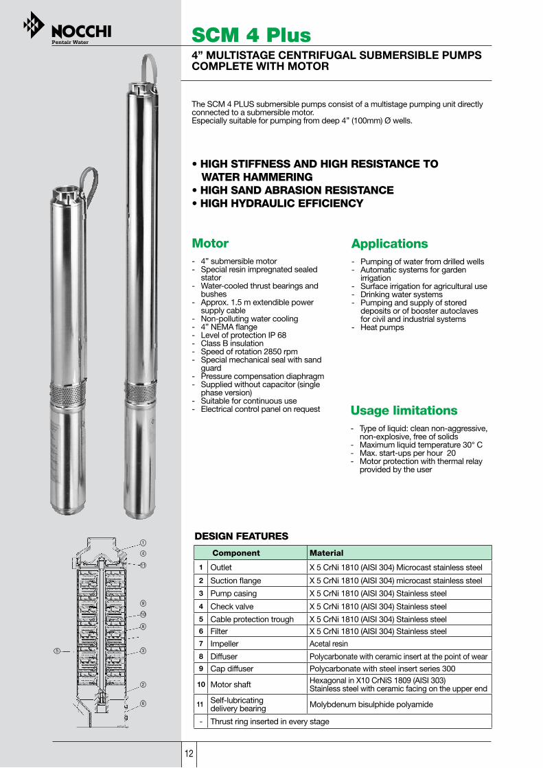
Applications- Pumping of water from drilled wells- Automatic systems for garden irrigation- Surface irrigation for agricultural use- Drinking water systems- Pumping and supply of stored deposits or of booster autoclaves for civil and industrial systems- Heat pumps
SCM 4 Plus4” MULTISTAGE CENTRIFUGAL SUBMERSIBLE PUMPS COMPLETE WITH MOTOR
The SCM 4 PLUS submersible pumps consist of a multistage pumping unit directly connected to a submersible motor.Especially suitable for pumping from deep 4’’ (100mm) Ø wells.
•HIGHSTIFFNESSANDHIGHRESISTANCETO WATER HAMMERING•HIGHSANDABRASIONRESISTANCE•HIGHHYDRAULICEFFICIENCY
Component Material
1 Outlet X 5 CrNi 1810 (AISI 304) Microcast stainless steel
2 Suction flange X 5 CrNi 1810 (AISI 304) microcast stainless steel
3 Pump casing X 5 CrNi 1810 (AISI 304) Stainless steel
4 Check valve X 5 CrNi 1810 (AISI 304) Stainless steel
5 Cable protection trough X 5 CrNi 1810 (AISI 304) Stainless steel6 Filter X 5 CrNi 1810 (AISI 304) Stainless steel
7 Impeller Acetal resin
8 Diffuser Polycarbonate with ceramic insert at the point of wear9 Cap diffuser Polycarbonate with steel insert series 300
10 Motor shaft Hexagonal in X10 CrNiS 1809 (AISI 303) Stainless steel with ceramic facing on the upper end
11 Self-lubricating delivery bearing Molybdenum bisulphide polyamide
- Thrust ring inserted in every stage
DESIGN FEATURES
Usage limitations- Type of liquid: clean non-aggressive, non-explosive, free of solids- Maximum liquid temperature 30° C- Max. start-ups per hour 20- Motor protection with thermal relay provided by the user
Motor- 4” submersible motor- Special resin impregnated sealed stator- Water-cooled thrust bearings and bushes- Approx. 1.5 m extendible power supply cable- Non-polluting water cooling- 4” NEMA flange- Level of protection IP 68- Class B insulation- Speed of rotation 2850 rpm- Special mechanical seal with sand guard- Pressure compensation diaphragm- Supplied without capacitor (single phase version)- Suitable for continuous use- Electrical control panel on request
11
4
9
10
8
5 3
2
6
1

13
SCM 4 Plus
Delivery connectionpoint in microcast AISI304 stainless steel withan internal tapereddouble profile with a stainless steel nonreturn valve and adouble slot for safety cable.
BENEFITS:It resets flow resistance offering maximumrigidity and highresistance to protec the pump against water hammering.
Floating impeller with suction point shim on stainless steel moulded with a diffusor cover. Thrust bearing inserted between the hub of the impeller and diffusor formed by one ceramic ring moulded with the diffusor and a free ringin graphite.“International Patent”
BENEFITS:This extraordinary technological innovation leads to a large increasein efficiency as well as high resistance toabrasion by sand andto dry operation.
Shaft guide bearing made with a self-lubricating closed bush in molybdenum bisulphide polyamide and stainless steel shaft with ceramic insert at the point of wear.
BENEFITS:Increases the life of the pump - protection against dry operation -high resistance to wear caused by sand.
Motor bracket and suction point in microcast AISI 304 stainless steel rigidly welded to the outer stainless steel liner. Stainless steel suction grid.
BENEFITS:This system offers high resistance to mechanical stresses caused by operating pressure.Maximum rigidity of the whole structure eliminates vibrations.
SC
M 4
Plu
s

14
MODEL
ATotal
lengthmm.
BMotor lengthmm.
CPump lengthmm.
DNML
Packing length
Totalweight
Kg.
SCM 4 PLUS 40/57 MSCM 4 PLUS 40/57 TSCM 4 PLUS 40/90 MSCM 4 PLUS 40/90 TSCM 4 PLUS 40/120 MSCM 4 PLUS 40/120 TSCM 4 PLUS 40/185 MSCM 4 PLUS 40/185 TSCM 4 PLUS 40/240 MSCM 4 PLUS 40/240 T
5765577176888578291109108113391310
242223271242299271327299356327
334334446446558558782782983983
1” 1/4
73071087084010109801260123014901460
11.810.814.012.716.114.919.217.922.220.8
SCM 4 PLUS 55/50 MSCM 4 PLUS 55/50 TSCM 4 PLUS 55/80 MSCM 4 PLUS 55/80 TSCM 4 PLUS 55/105 MSCM 4 PLUS 55/105 TSCM 4 PLUS 55/160 MSCM 4 PLUS 55/160 TSCM 4 PLUS 55/200 MSCM 4 PLUS 55/200 TSCM 4 PLUS 55/300 T
50949062859970067286283410269971317
242223271242299271327299356327356
267267357357401401535535670670961
6606407807508508301012990118011501470
11.310.313.111.814.913.717.316.019.818.422.3
SCM 4 PLUS 75/40 MSCM 4 PLUS 75/40 TSCM 4 PLUS 75/56 MSCM 4 PLUS 75/56 TSCM 4 PLUS 75/75 MSCM 4 PLUS 75/75 TSCM 4 PLUS 75/110 MSCM 4 PLUS 75/110 TSCM 4 PLUS 75/140 MSCM 4 PLUS 75/140 TSCM 4 PLUS 75/210 T
545526631602744716915887105810291372
242223271242299271327299356327356
3033033603604454455885887027021016
70068078075090087010701040120011801520
11.210.212.911.614.813.617.115.819.418.021.5
SCM 4 PLUS 115/30 MSCM 4 PLUS 115/30 TSCM 4 PLUS 115/50 MSCM 4 PLUS 115/50 TSCM 4 PLUS 115/65 MSCM 4 PLUS 115/65 TSCM 4 PLUS 115/95 MSCM 4 PLUS 115/95 TSCM 4 PLUS 115/122 MSCM 4 PLUS 115/122 TSCM 4 PLUS 115/185 TSCM 4 PLUS 115/245 T
48846960257368765982980197394412021525
242223271242299271327299356327356423
2462463313313883885025026176178461102
6406207507208408109809501120110013501680
11.010.012.811.514.413.216.615.318.817.420.825.0
SCM 4 PLUS 150/42 MSCM 4 PLUS 150/42 TSCM 4 PLUS 150/64 MSCM 4 PLUS 150/64 TSCM 4 PLUS 150/84 MSCM 4 PLUS 150/84 TSCM 4 PLUS 150/120 TSCM 4 PLUS 150/170 TSCM 4 PLUS 150/200 TSCM 4 PLUS 150/300 T
6526247907629299001142146618162407
299271327299356327356423590704
353353463463573573786104312261703 2”
800780940910108010501300162019702560
14.012.816.114.818.316.920.124.233.142.3
SCM 4 PLUS 250/53 MSCM 4 PLUS 250/53 TSCM 4 PLUS 250/78 TSCM 4 PLUS 250/100 TSCM 4 PLUS 250/127 TSCM 4 PLUS 250/185 T
9519221186155018332462
356327356514590704
595595830103612431758
110010701340170019832612
18.015.618.023.929.642.6
TABLE FOR CALCULATING PUMP LENGTH
96
DNM
A
CB
105
L
SCM 4 Plus
15
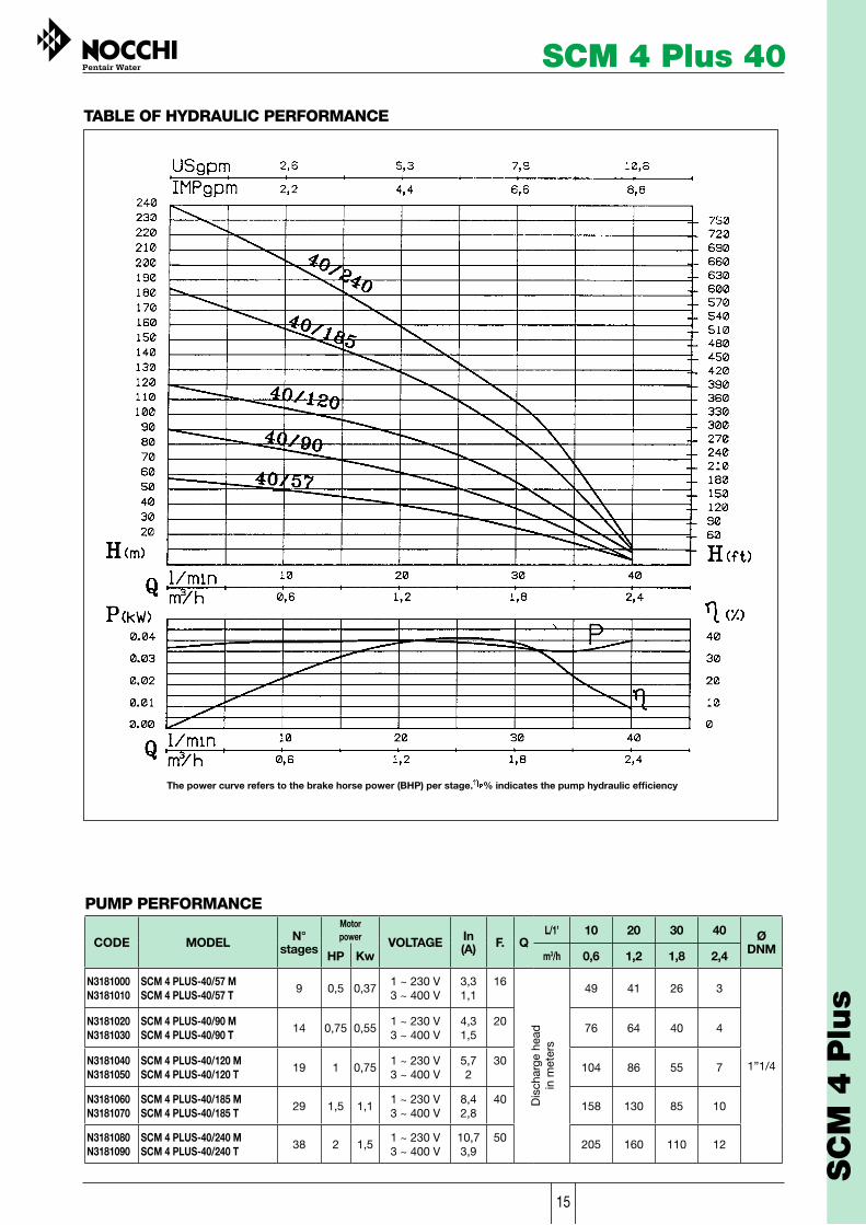
TABLE OF HYDRAULIC PERFORMANCE
The power curve refers to the brake horse power (BHP) per stage. % indicates the pump hydraulic efficiency
CODE MODEL N°stages
Motorpower VOLTAGE In
(A) F. QL/1’ 10 20 30 40 Ø
DNMHP Kw m3/h 0,6 1,2 1,8 2,4
N3181000N3181010
SCM 4 PLUS-40/57 MSCM 4 PLUS-40/57 T 9 0,5 0,37
1 ~ 230 V3 ~ 400 V
3,31,1
16
Dis
char
ge h
ead
in
met
ers
49 41 26 3
1”1/4
N3181020N3181030
SCM 4 PLUS-40/90 MSCM 4 PLUS-40/90 T 14 0,75 0,55
1 ~ 230 V3 ~ 400 V
4,31,5
2076 64 40 4
N3181040N3181050
SCM 4 PLUS-40/120 MSCM 4 PLUS-40/120 T 19 1 0,75
1 ~ 230 V3 ~ 400 V
5,72
30104 86 55 7
N3181060N3181070
SCM 4 PLUS-40/185 MSCM 4 PLUS-40/185 T 29 1,5 1,1
1 ~ 230 V3 ~ 400 V
8,42,8
40158 130 85 10
N3181080N3181090
SCM 4 PLUS-40/240 MSCM 4 PLUS-40/240 T 38 2 1,5
1 ~ 230 V3 ~ 400 V
10,73,9
50205 160 110 12
SCM 4 Plus 40
PUMP PERFORMANCE
SC
M 4
Plu
s

16
CODE MODEL N° Stages
Motor power
VOLTAGE In(A) µF. Q
L/1’ 10 20 30 40 50 Ø
DNM HP Kw m3/h 0,6 1,2 1,8 2,4 3
N3182000 N3182010
SCM 4 PLUS/55/50 M SCM 4 PLUS/55/50 T 6 0,5 0,37
1 ~ 230 V 3,3 16
Dis
char
ge h
ead
in
met
ers
47 42 36 23 8
1 “1/4
3 ~ 400 V 1,5
N3182020 N3182030
SCM 4 PLUS/55/80 M SCM 4 PLUS/55/80 T 10 0,75 0,55
1 ~ 230 V 4,3 20 75 66 55 35 12
3 ~ 400 V 1,6
N3182040 N3182050
SCM 4 PLUS/55/105 M SCM 4 PLUS/55/105 T 12 1 0,75
1 ~ 230 V 5,7 30 98 87 72 46 12
3 ~ 400 V 2
N3182060 N3182070
SCM 4 PLUS/55/160 M SCM 4 PLUS/55/160 T 18 1,5 1,1
1 ~ 230 V 8,440 145 132 110 70 24
3 ~ 400 V 2,8
N3182080 N3182090
SCM 4 PLUS/55/200 M SCM 4 PLUS/55/200 T 24 2 1,5
1 ~ 230 V 10,750 187 169 145 90 30
3 ~ 400 V 3,9
N3182100 SCM 4 PLUS/55/300 T 37 3 2,2 3 ~ 400 V 5,5 278 244 200 140 50
PUMP PERFORMANCE
The power curve refers to the brake horse power (BHP) per stage. % indicates the pump hydraulic efficiency
SCM 4 Plus 55
TABLE OF HYDRAULIC PERFORMANCE

17
TABLE OF HYDRAULIC PERFORMANCE
SCM 4 Plus 75
CODE MODEL N° Stages
Motor power
VOLTAGE In(A) µF. Q
L/1’ 20 30 40 50 60 Ø
DNM HP Kw m3/h 1,2 1,8 2,4 3 3,6
N3183000 N3183010
SCM 4 PLUS-75/40 M SCM 4 PLUS-75/40 T 6 0,5 0,37
1 - 230 V 3,3 16
Dis
char
ge h
ead
in
met
ers
36 33 28 23 15
1 “1/4
3 - 400 V 1,1
N3183020 N3183030
SCM 4 PLUS-75/56 M SCM 4 PLUS-75/56 T 8 0,75 0,55
1 - 230 V 4,3 20 50 45 40 32 21
3 - 400 V 1,6
N3183040 N3183050 N3186140
SCM 4 PLUS-75/75 M SCM 4 PLUS-75/75 T SCM 4 PLUS-75/75 T
11 1 0,75
1 - 230 V 5,7
30 67 62 55 45 30 3 - 400 V 2,1
3 - 230 V 3,7
N3183060 N3183070
SCM 4 PLUS-75/110 M SCM 4 PLUS-75/110 T 16 1,5 1,1
1 - 230 V 8,4
40 100 92 82 68 44 3 - 400 V 3,2
N3183080 N3183090
SCM 4 PLUS-75/140 M SCM 4 PLUS-75/140 T 20 2 1,5
1 - 230 V 10,7
50 127 116 105 86 57 3 - 400 V 3,9
N3183100 SCM 4 PLUS-75/210 T 30 3 2,2 3 - 400 V 5,5 186 170 155 130 80
PUMP PERFORMANCE
The power curve refers to the brake horse power (BHP) per stage. % indicates the pump hydraulic efficiency
SC
M 4
Plu
s

18
CODE MODEL N° Stages
Motor power
VOLTAGE In(A) µF. Q
L/1’ 30 40 50 60 80 90 100 Ø
DNM HP Kw m3/h 1,8 2,4 3 3,6 4,8 5,4 6
N3184000 N3184010
SCM 4 PLUS-115/30 M SCM 4 PLUS-115/30 T 4 0,5 0,37
1 ~ 230 V 3,3 1,1
16
Dis
char
ge h
ead
in
met
ers
26 24 22 20 13 9 6,4
1”1/4
3 ~ 400 VN3184020 N3184030
SCM 4 PLUS-115/50 M SCM 4 PLUS-115/50 T 7 0,75 0,55
1 ~ 230 V 4,3 1,6
20 46 43 40 36 23 16 10 3 ~ 400 V
N3184040 N3184050 N3186150
SCM 4 PLUS-115/65 M SCM 4 PLUS-115/65 T SCM 4 PLUS-115/65 T
9 1 0,75 1 ~ 230 V 5,7
2,1 3,7
30 58 55 51 46 29 20 11 3 ~ 400 V
3 ~ 230 VN3184060 N3184070 N3186160
SCM 4 PLUS-115/95 M SCM 4 PLUS-115/95 T SCM 4 PLUS-115/95 T
13 1,5 1,1 1 ~ 230 V 8,4
3,2 5,2
40 83 80 74 67 43 30 18 3 ~ 400 V
3 ~ 230 V N3184080 N3184090
SCM 4 PLUS-115/122 M SCM 4 PLUS-115/122 T 17 2 1,5
1 ~ 230 V 10,7 3,9
50 109 106 98 88 55 38 21 3 ~ 400 V
N3184100 SCM 4 PLUS-115/185 T 24 3 2,2 3 ~ 400 V 5,5 160 153 143 130 85 58 31
N3184110 SCM 4 PLUS-115/245 T 33 4 3 3 ~ 400 V 7,8 218 210 198 179 118 84 47
PUMP PERFORMANCE
The power curve refers to the brake horse power (BHP) per stage. % indicates the pump hydraulic efficiency
SCM 4 Plus 115
TABLE OF HYDRAULIC PERFORMANCE

19
CODE MODEL N° Stages
Molor power
VOLTAGE In(A) µF. Q
L/1’ 40 50 60 80 100 120 140 Ø
DNM HP Kw m3/h 2,4 3 3,6 4,8 6 7,2 8,4
N3185000 N3185010 N3186170
SCM 4 PLUS-150/42 M SCM 4 PLUS-150/42 T SCM 4 PLUS-150/42 T
6 1 0,75 1 ~ 230V3 ~ 400 V3 ~ 230 V
5,72
3,530
Dis
char
ge h
ead
in
met
ers
38 37 36 33 26 17 10
2”
N3185020 N3185030 N3186180
SCM 4 PLUS-150/64 M SCM 4 PLUS-150/64 T SCM 4 PLUS-150/64 T
9 1,5 1,1 1 ~ 230 V3 ~ 400 V3 ~ 230 V
8,42,84,9
40 59 58 57 50 39 27 15
N3185040 N3185050N3186190
SCM 4 PLUS-150/84 M SCM 4 PLUS-150/84 T SCM 4 PLUS-1 50/84 T
12 2 1,5 1 ~ 230 V3 ~ 400 V3~ 230 V
10,73,96,7
50 80 78 75 64 50 34 20
N3185060 SCM 4 PLUS-150/120 T 17 3 2,2 3 ~ 400 V 5,9 116 113 108 96 77 53 26
N3185070 SCM 4 PLUS-150/170 T 24 4 3 3 ~ 400 V 7,5 160 157 152 134 106 69 30
N3185080 SCM 4 PLUS-150/200 T 29 5,5 4 3 ~ 400 V 9,9 191 188 179 152 112 71 32
N3185090 SCM 4 PLUS-150/300 T 42 7,5 5,5 3 ~ 400 V 12,6 292 290 285 252 210 155 82
PUMP PERFORMANCE
The power curve refers to the brake horse power (BHP) per stage. % indicates the pump hydraulic efficiency
SCM 4 Plus 150
TABLE OF HYDRAULIC PERFORMANCE
SC
M 4
Plu
s

20
SCM 4 Plus 250
TABLE OF HYDRAULIC PERFORMANCE
PUMP PERFORMANCE
MODELCODE
Motorpower
VOLTAGE ln(A)
µF. QL/1'
m3/h
140
8,4
100
6HP Kw
120
7,2
2"
DNM
Ø
Dis
char
ge h
ead
in m
eter
s
180
10,8
200
12
220
13,2
240
14,4
9
13
17
21
31
SCM 4 PLUS-250/53 M SCM 4 PLUS-250/53 T SCM 4 PLUS-250/53 T
43
SCM 4 PLUS-250/78 T 63
83
106
N3186000 N3186010 N3186200
N3186020
2 1,51 ~ 230 V3 ~ 400 V3 ~ 230 V
3 2,2 3 ~ 400 V
4 3
5,5 4
1527,5 5,5
N3186030
N3186040
N3186050
SCM 4 PLUS-250/100 T
SCM 4 PLUS-250/127 T
SCM 4 PLUS-250/185 T
3 ~ 400 V
3 ~ 400 V
3 ~ 400 V
41 37 26 18 11
59 54 41 30 18
78 66 54 41 24
100 90 68 49 31
141 127 81 57 36
4
7
9
14
18
10,73,56,7
5,9
7,8
9,9
12,6
50
N˚Stages
SCM 4 Plus 250
The power curve refers to the brake horse power (BHP) per stage. % indicates the pump hydraulic efficiency

21
SCM 4 HF 4004” MULTISTAGE CENTRIFUGAL SUBMERSIBLEPUMPS COMPLETE WITH MOTOR
SCM 4 HF 400
143
Motor– 4” submersible motor– Special resin impregnated sealed stator– Water-cooled thrust bearings and bushes– Approx. 1,5 m extendible power supply cable– Non-polluting water cooling– 4” NEMA flange– Level of protection IP68– Class B insulation– Speed of rotation 2850 rpm– Special mechanical seal with sand guard– Pressure compensation diaphragm– Supplied without capacitor (single phase version)– Suitable for continuous use– Electrical control panel on request
Applications– Pumping of water from drilled wells– Automatic systems for garden irrigation– Surface irrigation for agricultural use– Drinking water systems– Pumping and supply of stored deposits or of booster autoclaves for civil and industrial systems– Heat pumps
Usage limitations- Type of liquid: clean, non aggressive, non-explosive, free of solids- Maximum liquid temperature 30° C- Max. start-ups per hour 20- Motor protection with thermal relay provided by the user
SCM 4HF 400 high flow rate submersible pumps consist of a multistage hydraulic enddirectly connected to a submersible motor. Especially suitable for pumping from deepØ 4” (100 mm) wells
Washer / thrust
Component
Discharge
Motor bracket
Screen
ImpellerDiffuser
Material
300 series stainless steel - 2” BSP threads
Microcast stainless steel (300 series)
300 series stainless steel
DESIGN FEATURES
12
3 Shell
45
Glass filled Polycarbonate6
7Glass filled Noryl®
8
• BUILT TO DELIVER LONG TERM, TROUBLE-FREE SERVICE• HIGH HYDRAULIC EFFICIENCY• HIGH FLOW
Cable guard 300 series stainless steel
9
Motor shaft (hydraulic end)
Acetal
10
Top bearing
Phenolic
300 series stainless steel
Hexagonal in stainless steel (300 series)
Thrust ring inserted in every stage
1
8
7
6
4
2
10
3
5
9

22144
SCM 4 HF 4004” MULTISTAGE CENTRIFUGAL SUBMERSIBLE PUMPS COMPLETE WITH MOTOR
TABLE OF HYDRAULIC PERFORMANCE
DIMENSIONS AND WEIGHTS
MODEL
Dimension mm.
A B DNM
kg
C
2536 698SCM4HF 400/100 T 39,41838 2” BSP
914 384SCM4HF 400/30 M 21,5530 2” BSP
1036 356SCM4HF 400/50 T 21,5680 2” BSP
SCM4HF 400/30 T
SCM4HF 400/80 T
980 305 192” BSP
2060 584 332” BSP
675
1476
Weight
kg
29,4
14,5
13,5
12
24
kg
10
7
8
7
9
Totallength
Motorlength
Pumplength
total motor pump
PUMP PERFORMANCE
CODEMotorPower
kWVOLTAGE Amp. µF. Q
L/1'
m3/h
100 300 350
HP 15 216
150
9
200
12
250
15N˚
stages
7
��
���
�
��
���
�
MODEL
3 ~ 400 V2,23 39,2 35,5 31,143 25,1 19,25,5 11
3 ~ 400 V45,5 65 57,7 50,371 42,2 32,610 18
3 ~ 400 V5,57,5 88,8 80 69,696,3 57,7 4312,6 23
Disc
harg
e he
adin
met
ers
1 ~ 230 V1,52 25 22,2 19,527,4 15,5
10,750
3 ~ 400 V 3,9
SCM4HF 400/50 T
SCM4HF 400/80 T
SCM4HF 400/100 T
SCM4HF 400/30 M
SCM4HF 400/30 T
N3186110
N3186120
N3186130
N3186090
N3186100
SCM 4 HF 400

23
4” SUBMERSIBLE PUMPS
N1050120
CODE
SCM 4 PLUS 75/40
MODEL
36
20Ql/1'
33
30
28
40
23
50
15
60 NECESSARYMOTOR
HP 0,5
Dis
char
ge h
ead
in m
eter
s
N1050020 SCM 4 PLUS 40/90 76 64 40 4 HP 0,75
N1050030 SCM 4 PLUS 40/120 104 86 55 7 HP 1
N1050040 SCM 4 PLUS 40/185 158 130 85 10 HP 1,5
N1050050 SCM 4 PLUS 40/240 205 160 110 12 HP 2
N1050060 SCM 4 PLUS 55/50 47 42 36 23 8 HP 0,5
N1050070 SCM 4 PLUS 55/80 75 66 55 35 12 HP 0,75
N1050080 SCM 4 PLUS 55/105 98 87 72 46 15 HP 1
N1050090 SCM 4 PLUS 55/160 145 132 110 70 24 HP 1,5
N1050100 SCM 4 PLUS 55/200 187 169 145 90 30 HP 2
N1050110 SCM 4 PLUS 55/300 278 244 200 140 50 HP 3
N1050130 SCM 4 PLUS 75/56 50 45 40 32 21 HP 0,75
N1050140 SCM 4 PLUS 75/75 67 62 55 45 30 HP 1
N1050150 SCM 4 PLUS 75/110 100 92 82 68 44 HP 1,5
N1050160 SCM 4 PLUS 75/140 127 116 105 86 57 HP 2
N1050170 SCM 4 PLUS 75/210 186 170 155 130 80 HP 3
CODE MODEL 10Ql/1' 20 30 40 NECESSARYMOTOR
Dhi
scar
ge h
ead
in m
eter
s
CODE MODEL 10Ql/1' 20 30 40 50 NECESSARYMOTOR
Dhi
scar
ge h
ead
in m
eter
s
N1050010 SCM 4 PLUS 40/57 49 41 37 26 HP 0,5
SCM 4 Plus / HF PUMP-END
SC
M 4
Plu
s /
HF P
UM
P-E
ND

24
SCM 4 Plus / HF PUMP-END4” SUBMERSIBLE PUMPS
100 150 200 250 300 350CODE MODEL Ql/1' NECESSARYMOTOR
100 120 140 180 200 220 240CODE MODEL Ql/1' NECESSARYMOTOR
CODE MODEL Ql/1' 40 50 60 80 100 120 140 NECESSARYMOTOR
CODE MODEL 30Ql/1' 40 50 60 80 90 100 NECESSARYMOTOR
N1050180 SCM 4 PLUS 115/30 26 24 22 20 HP 0,513 9 6,4
N1050190 SCM 4 PLUS 115/50 46 43 40 36 HP 0,7523 16 10
N1050200 SCM 4 PLUS 115/65 58 55 51 46 HP 129 20 11
N1050210 SCM 4 PLUS 115/95 83 80 74 67 HP 1,543 30 18
N1050220 SCM 4 PLUS 115/122 109 106 98 88 HP 255 38 21
N1050230 SCM 4 PLUS 115/185 160 153 143 130 HP 385 58 31
N1050240 SCM 4 PLUS 115/245 218 210 198 179 HP 4118 84 47
N1050250 SCM 4 PLUS 150/42 38 37 36 33 HP 126 17 10
N1050260 SCM 4 PLUS 150/64 59 58 57 50 HP 1,539 27 15
N1050270 SCM 4 PLUS 150/84 80 78 75 64 HP 250 34 20
N1050280 SCM 4 PLUS 150/120 116 113 118 96 HP 377 53 26
N1050290 SCM 4 PLUS 150/170 160 157 152 134 HP 4106 69 30
N1050300 SCM 4 PLUS 150/200 191 188 179 152 HP 5,5112 71 32
N1050310 SCM 4 PLUS 150/300 292 290 285 252 HP 7,5210 255 82
N1050320 SCM 4 PLUS 250/53 43 41 37 26 HP 218 11 4
N1050330 SCM 4 PLUS 250/78 63 59 54 41 HP 330 18 7
N1050340 SCM 4 PLUS 250/100 83 78 66 54 HP 441 24 9
N1050350 SCM 4 PLUS 250/127 106 100 90 68 HP 5,549 31 14
N1050360 SCM 4 PLUS 250/185 152 141 127 81 HP 7,557 36 18
N1057980 SCM 4HF 400/30 27,4 25 22,2 19,5 HP 215,5
N1057990 SCM 4HF 400/50 43 39,2 35,5 31,1 HP 325,1 19,2
N1058000 SCM 4HF 400/80 71 65 57,7 50,3 HP 5,542,2 32,6
N1058010 SCM 4HF 400/100 96,3 88,8 80 69,6 HP 7,557,7 43
Dis
char
ge h
ead
in m
eter
sD
isch
arge
hea
d in
met
ers
Dis
char
ge h
ead
in m
eter
sD
isch
arge
hea
d in
met
ers

25
MOTORS 4”4” SUBMERSIBLE MOTORS FOR SCM 4 PLUSNEMA SPEC WITH PART ELECTRICAL CABLE
WATER COOLED
OIL COOLED
Hz
Hz
222P0540-C 3 2,2 1 ~ 230V 50
Hz
Hz
222P0010 0,5 0,37 1 ~ 230V 50
221P0030 0,5 0,37 3 ~ 400V 50
222P0020 0,75 0,55 1 ~ 230V 50
221P0040 0,75 0,55 3 ~ 400V 50
222P0030 1 0,74 1 ~ 230V 50
221P0050 1 0,74 3 ~ 400V 50
222P0040 1,5 1,1 1 ~ 230V 50
221P0060 1,5 1,1 3 ~ 400V 50
222P0050 2 1,5 1 ~ 230V 50
221P0070 2 1,5 3 ~ 400V 50
221P0080 3 2,2 3 ~ 400V 50
221P1010 4 3 3 ~ 400V 50
221P1000 5,5 4 3 ~ 400V 50
221P0740-C 0,5 0,37 3 ~ 400V 50
221P0750-C 0,75 0,55 3 ~ 400V 50
221P0760-C 1 0,74 3 ~ 400V 50
221P0990-C 1 0,74 3 ~ 230V 50
221P0770-C 1,5 1,1 3 ~ 400V 50
222P0390-C 0,5 0,37 1 ~ 230V 50
222P0400-C 0,75 0,55 1 ~ 230V 50
222P0310-C 1 0,74 1 ~ 230V 50
222P0320-C 1,5 1,1 1 ~ 230V 50
222P0330-C 2 1,5 1 ~ 230V 50
221P0600-C 5,5 4 3 ~ 400V 50
221P0590-C 4 3 3 ~ 400V 50
221P0580-C 3 2,2 3 ~ 400V 50
221P0920-C 2 1,5 3 ~ 230V 50
221P0570-C 2 1,5 3 ~ 400V 50
221P0910-C 1,5 1,1 3 ~ 230V 50
221P0610-C 7,5 5,5 3 ~ 400V 50
VOLTAGE
VOLTAGE
VOLTAGE
CODEHP kW
POWER VOLTAGE
CODEHP kWPOWER
CODEHP kWPOWER
CODEHP kWPOWER
MO
TO
RS 4
”

26
SA6” MULTISTAGE SUBMERSIBLE PUMPS COMPLETE WITH MOTOR
The SA submerged pumps consist of a multistage pumping unit directly connected to a submersible motor. Especially suitable for pumping from deep 6’’ (150mm) Ø wells.Flow rate up to 1100 l/min.
Usage limitations- Type of liquid: clean non-aggressive, non-explosive, free of solids- Maximum liquid temperature 30° C- Max. start-ups per hour: 20- Motor protection with thermal relay provided by the user- Maximum quantity of sand present: 40 g/m3
Applications- Civil and industrial supply systems- Overhead or surface irrigation- Boosting- Firefighting- Various civil and industrial applications- Mains water supply systems- Heat pumps
Motor- 6” Franklin submersible motor- Special resin impregnated sealed stator- Water-cooled thrust bearings and bushes- Approx. 1.5 m extendible power supply cable- Non-polluting water cooling- 6” NEMA flange- Level of protection IP68. Class F insulation- Speed of rotation 2850 rpm- Special mechanical seal with sand guard- Pressure compensation diaphragm- Suitable for continuous use- Electrical control panel on request- Direction of rotation anticlockwise (seen from the delivery end)
Component Material1 Outlet EN GJS 400 (GS400) Nodular cast iron
2 Suction flange EN GJS 400 (GS400) Nodular cast iron
3 Outer liner Stainless steel
4 Cable protection filter and trough Stainless steel
5 Shaft Stainless steel
6 ImpellerTechnopolymer/Polycarbonate. SA 615 - SA 625: radial impellers SA 630 - SA 650: semiaxial impellers
7 Diffuser Noryl GNF 2V
8 Wear rings NBR 70 Rubber
9 Bush bearings Stainless steel
10 Diffuser Bronze/rubber
DESIGN FEATURES
• INTEGRATED CHECK VALVE

27
TABLE OF HYDRAULIC PERFORMANCE
Ø MOTOR
���
���
�
��
DNM = 3” gas
Pump casing
Ø Motor Electric pump
435 87 791 22
478 87 901 27
511 87 1056 30
625 87 1329 41
738 137 1384 58
966 137 1677 67
L1(mm) (mm)
L(mm) (kg)
WeightModel
SA 615/4
SA 615/5
SA 615/6
SA 615/9
SA 615/12
SA 615/18
SA 615/4* 62 D8760KKK 3 2,2 3 ~ 400 V
SA 615/5* 78 D8761KKK 4 3 3 ~ 400 V
SA 615/6* 94 D8762KKK 5,5 4,0 3 ~ 400 V
SA 615/9* 140 D8763KKK 7,5 5,5 3 ~ 400 V
SA 615/12 187 D8764KKK 10 7,5 3 ~ 400 V
SA 615/18 281 D8765KKK 15 11 3 ~ 400 V
60
74
89
134
179
268
55
69
82
123
166
250
51
63
75
113
152
231
46
57
68
101
136
210
39
49
58
88
118
180
31
39
46
70
92
138
5,5
7,5
9,9
12,6
16
23,3
4
5
6
9
12
18
PUMP PERFORMANCE
MODELCODE
MotorPower
kWVOLTAGE Amp. Q
L/1'
m3/h
0 N.Stages
0
300
18
160
9,6
200
12HP
120
7,2
230
13,8
260
15,6
Dis
char
ge h
ead
in m
eter
s
* WITH 4’’ MOTOR
SA 615
SA
The power curve refers to the brake horse power (BHP) per stage. % indicates the pump hydraulic efficiency

28
SA 625
164
TABLE OF HYDRAULIC PERFORMANCE
Ø MOTOR
���
���
�
��
DNM = 3” gas
Pumpcasing
Ø Motor Electric pump
L1(mm) (mm)
L(mm) (kg)
WeightModel
511 87 1056 30
625 87 1329 41
738 137 1384 57
966 137 1677 66
1193 137 1969 75
1474 137 2316 86
SA 625/4
SA 625/6
SA 625/8
SA 625/12
SA 625/16
SA 625/20
PUMP PERFORMANCE
MODELCODE
Motorpower
kWVOLTAGE Amp. Q
L/1'
m3/h
0N.Stages
0
600
34
300
18
350
21HP
200
12
400
24
500
30
SA 625/4* 61 D8771KKK 5,5 4,0 3 ~ 400 V
SA 625/6* 91 D8772KKK 7,5 5,5 3 ~ 400 V
SA 625/8 122 D8773KKK 10 7,5 3 ~ 400 V
SA 625/12 182 D8774KKK 15 11 3 ~ 400 V
SA 625/16 243 D8775KKK 20 15 3 ~ 400 V
SA 625/20 304 D8776KKK 25 18,5 3 ~ 400 V
53
80
106
159
212
265
48
71
95
143
190
238
44
66
87
131
177
220
40
59
79
119
159
198
28
43
58
88
118
146
17
25
34
50
67
84
9,9
12,6
16
23,3
31,3
38,5
4
6
8
12
16
20
* WITH 4’’ MOTOR
Dis
char
ge h
ead
in m
eter
s
SA 625
The power curve refers to the brake horse power (BHP) per stage. % indicates the pump hydraulic efficiency

29
SA 630
165
SA
SA 630
TABLE OF HYDRAULIC PERFORMANCE
PUMP PERFORMANCE
MODELCODE
Motorpower
kWVOLTAGE Amp. Q
L/1'
m3/h
0N.Stages
0
800
48
400
24
500
30
Pump casing
ØMotor Electric pump
L1(mm) (mm)
L(mm) (kg)
WeightModel
HP
300
18
600
36
700
42
Ø MOTOR
145
DNM
L
L1
DNM = 3” gas
522 87 1226 39
582 137 1228 54
762 137 1473 62
882 137 1658 70
1002 137 1844 78
SA 630/4
SA 630/5
SA 630/8
SA 630/10
SA 630/12
SA 630/4* 63 D8782KKK 7,5 5,5 3 ~ 400 V
SA 630/5 78 D8783KKK 10 7,5 3 ~ 400 V
SA 630/8 126 D8784KKK 15 11 3 ~ 400 V
SA 630/10 157 D8785KKK 20 15 3 ~ 400 V
SA 630/12 188 D8786KKK 25 18,5 3 ~ 400 V
57
72
114
143
171
53
67
106
133
160
47
59
94
119
143
40
50
80
101
122
30
37
62
76
92
19
23
37
45
55
12,6
16
23,3
31,3
38,5
4
5
8
10
12
* WITH 4’’ MOTOR
Dis
char
ge h
ead
in m
eter
s
SA
The power curve refers to the brake horse power (BHP) per stage. % indicates the pump hydraulic efficiency

30
SA 650
166
TABLE OF HYDRAULIC PERFORMANCE
Ø MOTOR
145
DNM
L
L1
DNM = 3” gas
Pump casing
ØMotor Electric pump
L1(mm) (mm)
L(mm) (kg)
WeightModel
PUMP PERFORMANCE
MODELCODE
Motorpower
kWVOLTAGE Amp. Q
L/1'
m3/h
0N.Stages
0
1100
66
700
42
800
48HP
600
36
900
54
1000
60
522 137 1168 53
642 137 1353 61
822 137 1598 69
882 137 1724 76
1002 137 1909 84
SA 650/4
SA 650/6
SA 650/9
SA 650/10
SA 650/12
SA 650/4 54 D8792KKK 10 7,5 3 ~ 400 V
SA 650/6 81 D8793KKK 15 11 3 ~ 400 V
SA 650/9 122 D8794KKK 20 15 3 ~ 400 V
SA 650/10 135 D8795KKK 25 18,5 3 ~ 400 V
SA 650/12 162 D8796KKK 30 22 3 ~ 400 V
40
59
90
101
120
35
53
80
90
107
31
46
68
77
93
25
37
57
63
75
19
29
44
49
59
13
20
30
33
40
16
23,3
31,3
38,5
45,3
4
6
9
10
12
Dis
char
ge h
ead
in m
eter
s
SA 650
The power curve refers to the brake horse power (BHP) per stage. % indicates the pump hydraulic efficiency

31
SA PUMP-ENDSSA PUMP-ENDS
167
6” SUBMERSIBLE PUMPS
SA
PU
MP
-EN
DS
N1051300
N1051310
N1051320
N1051330
N1051340
N1051350
SA 615/4 *
SA 615/5 *
SA 615/6 *
SA 615/9 *
SA 615/12
SA 615/18
HP 3
HP 4
HP 5,5
HP 7,5
HP 10
HP 15
62 60 55 51 46 39 31
78 74 69 63 57 49 39
94 89 82 75 68 58 46
140 134 123 113 101 88 70
187 179 166 152 136 118 92
281 268 250 231 210 180 138
N1051360
N1051370
N1051380
N1051390
N1051400
N1051410
SA 625/4 *
SA 625/6 *
SA 625/8
SA 625/12
SA 625/16
SA 625/20
HP 5,5
HP 7,5
HP 10
HP 15
HP 20
HP 25
61 53 48 44 40 28 17
91 80 71 66 59 43 25
122 106 95 87 79 58 31
182 159 143 131 119 88 50
243 212 190 177 159 118 67
304 265 238 220 198 146 84
N1051420
N1051430
N1051440
N1051450
N1051460
SA 630/4 *
SA 630/5
SA 630/8
SA 630/10
SA 630/12
HP 7,5
HP 10
HP 15
HP 20
HP 25
63 57 53 47 40 30 19
78 72 67 59 50 37 23
126 114 106 94 80 62 37
157 143 133 119 101 76 45
188 171 160 143 122 92 55
N1051470
N1051480
N1051490
N1051500
N1051510
SA 650/4
SA 650/6
SA 650/9
SA 650/10
SA 650/12
HP 10
HP 15
HP 20
HP 25
HP 30
54 40 35 31 25 19 13
81 59 53 46 37 29 20
122 90 80 68 57 44 30
135 101 90 77 63 49 33
162 120 107 93 75 59 40
* FOR 4’’ MOTOR
CODE MODEL 0Ql/1' 120 160 200 230 260 300 NECESSARYMOTOR
Dhi
scar
ge h
ead
in m
eter
sD
hisc
arge
hea
d in
met
ers
Dhi
scar
ge h
ead
in m
eter
sD
isch
arge
hea
d in
met
ers
0Ql/1' 200 300 350 400 500 600 NECESSARYMOTOR
0Ql/1' 300 400 500 600 700 800 NECESSARYMOTOR
0Ql/1' 600 700 800 900 1000 1100 NECESSARYMOTOR
CODE
CODE
CODE
MODEL
MODEL
MODEL
6” SUBMERSIBLE PUMPS
SA
PU
MP
-EN
DS

32
6” MOTORS
168
ELECTRIC MOTORS Ø 6” FOR SUBMERSIBLE PUMPSNEMA SPEC WITH PART ELECTRICAL CABLE
ZA000420
ZA000430
ZA000440
ZA000450
ZA000460
ZA000470
CABLE 4 x 1
CABLE 4 x 1,5
CABLE 4 x 2,5
CABLE 4 x 4
CABLE 4 x 6
CABLE 4 x 10
NEOPRENE HO7 RNF 4 WIRE CABLE 1 MM2 WIRES
NEOPRENE HO7 RNF 4 WIRE CABLE 1,5 MM2 WIRES
NEOPRENE HO7 RNF 4 WIRE CABLE 2,5 MM2 WIRES
NEOPRENE HO7 RNF 4 WIRE CABLE 4 MM2 WIRES
NEOPRENE HO7 RNF 4 WIRE CABLE 6 MM2 WIRES
NEOPRENE HO7 RNF 4 WIRE CABLE 10 MM2 WIRES
ZA003370
ZA003390
ZA003380
ZA009410
ZA009430
ZA009450
JOINT KIT 2,5
JOINT KIT 6
JOINT KIT 10
JOINT 2,5
JOINT 6
JOINT 10
HEAT-SHRINK SPLICING KIT FOR CABLES UP TO 4 X 2,5
HEAT-SHRINK SPLICING KIT FOR CABLES UP TO 4 X 6
RESIN FILLED SPLICING KIT
HEAT-SHRINK SPLICING JOINT FOR CABLES UP TO 1 - 2,5 mmq
HEAT-SHRINK SPLICING JOINT FOR CABLES UP TO 4 - 6 mmq
RESIN FILLED SPLICING JOINT FOR CABLES UP TO 4 X 10 mmq
CABLES AND JUNCTIONS
Hz
WATER COOLED
CODEHP kWPOTENZA
VOLTAGELnA
2210P0930-C
2210P0810-C
2210P0820-C
2210P0940-C
2210P0830-C
2210P0840-C
2210P0880-C
2210P0890-C
2210P0080-C
2210P0090-C
2210P1100-C
5,5
7,5
10
12,5
15
20
25
30
40
50
60
4
5,5
7,5
9,3
11
15
18,5
22
30
37
45
3 ~ 400V
3 ~ 400V
3 ~ 400V
3 ~ 400V
3 ~ 400V
3 ~ 400V
3 ~ 400V
3 ~ 400V
3 ~ 400V
3 ~ 400V
3 ~ 400V
9,3
12,5
16
20,7
23,3
31,3
38,5
45,3
63,5
73
93,9
50
50
50
50
50
50
50
50
50
50
50

33169
SELECTION OF ELECTRIC CABLE FOR SUBMERSIBLE PUMPS
MAXIMUM ELECTRIC CABLE LENGTH
Voltage loss 3% - Maximum environmental temperature +30%
MOTOR
KW
Direct starting3 ~ 400 V - 50 Hz
777523384262
0.370.550.751.11.52.234
3515.5
192131967252
MOTOR
kW
1 four - pole cable4 x …mm2
1.5 2.5 4 6 10Cables - L max in m.
2587.5 642109.2 5217611 7014913 601301510518.58922
32021816012088
103
84
349256192140
106
90
154
126
385289210
MOTOR
kW
1 ~ 220 ÷ 240 V - 50 Hz
1 four - pole cable4 x …mm2
Cables - max L in m.
0.37
0.55
0.75
1.1
1.5
2.2
114
77
56
38
6 101.5 2.5 4
47
32
191
128
94
64
75
51
305
205
151
103
113
77
308
226
154
188
128
376
257
3 ~ 230 V - 50 Hz
1 four - pole cable4 x …mm2
Cables - L max in m.
0.75
1.1
1.5
107
76
57
6 101.5 2.5 4
179
127
96
269
191
144
255
192 289
359
383
6”
MO
TO
RS
6” MOTORS

35
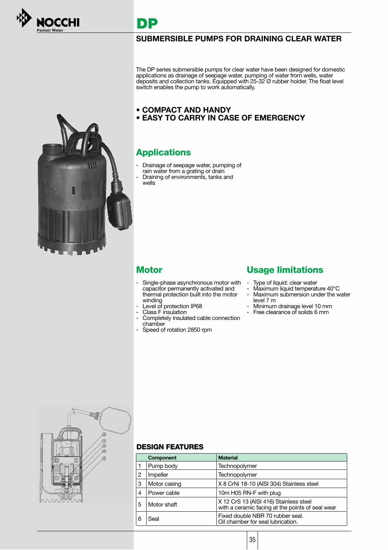
Component Material
1 Pump body Technopolymer
2 Impeller Technopolymer
3 Motor casing X 8 CrNi 18-10 (AISI 304) Stainless steel
4 Power cable 10m H05 RN-F with plug
5 Motor shaft X 12 CrS 13 (AISI 416) Stainless steelwith a ceramic facing at the points of seal wear
6 Seal Fixed double NBR 70 rubber seal.Oil chamber for seal lubrication.
DPSUBMERSIBLE PUMPS FOR DRAINING CLEAR WATER
The DP series submersible pumps for clear water have been designed for domestic applications as drainage of seepage water, pumping of water from wells, water deposits and collection tanks. Equipped with 25-32 Ø rubber holder. The float level switch enables the pump to work automatically.
• COMPACT AND HANDY• EASY TO CARRY IN CASE OF EMERGENCY
Applications- Drainage of seepage water, pumping of rain water from a grating or drain- Draining of environments, tanks and wells
Motor- Single-phase asynchronous motor with capacitor permanently activated and thermal protection built into the motor winding- Level of protection IP68- Class F insulation- Completely insulated cable connection chamber- Speed of rotation 2850 rpm
Usage limitations- Type of liquid: clear water- Maximum liquid temperature 40°C- Maximum submersion under the water level 7 m- Minimum drainage level 10 mm- Free clearance of solids 6 mm
DESIGN FEATURES

36
CODE MODEL
AbsorbedPower VOLTAGE Amp µF. Q
L/1’ 0 25 50 100 150
HP KW m3/h 0 1,5 3 6 9
N1041190 DP 130/60,4 0,3 1 ~ 230 V 1,4 6,3
Dis
char
ge
head
in
met
ers
7 6 4,5 1,7N1041170 DP130/6 AUT*
N1041180 DP 180/7 AUT* 0,5 0,37 1 ~ 230 V 1,6 10 7 6,2 5,2 3,2 1,1
*Automatic version equipped with float switch
DP
TABLE OF HYDRAULIC PERFORMANCE
PUMP PERFORMANCE
TABLE OF SIZES AND WEIGHTS
Model
Dimensions mm. Weight
A B C D E kg
DP 130/6 AUT 236 10 330 150 256 3,9
DP 180/7 AUT 236 10 330 150 256 4,2
* Start and stop level refers to the version equipped with floating switch.The minimum drainage level refers to the manual version

37
SIMER PUMPS SUBMERSIBLE PUMPS FOR DRAINING CLEAR WATER
Made in U.S.A.
The SIMO submersible pumps for clear water have been designed for drainage of seepage water, pumping of water from sump pits, water deposits and collection tanks.
SIMER SIMO • EXCELLENT FOR INDUSTRIAL DRAINAGE • MINIMUM DRAINAGE LEVEL 3 mm • EQUIPPED WITH 13-19-25 Ø ADAPTABLE CONNECTOR
Applications - Drainage of seepage water, pumping of rain water from grating or drain - Emptying of water deposits, collection tanks and wells.
Motor - Single-phase asynchronous oil cooled motor with capacitor permanently activated and thermal protection built into the motor winding - Level of protection IPX8 - Class F insulation - Speed rotation 2850 rpm
Usage limitations - Type of liquid: clear water - Maximum liquid temperature 50° C - Maximum submersion under the water level 2 m - Minimum drainage level 3 mm - Minimum priming level 20 mm
DESIGN FEATURES
Applications - Drainage of seepage water, pumping of rain water from grating or drain - Create streams and waterfalls for gardens - Residential application - Marine application
Motor - Syncronous electric motor, 12 V DC 21 Amp. - Level of protection IP X8
Usage limitations - Type of liquid: clear water - Maximum liquid temperature 50°C - Minimum liquid temperature 1.7 °C - Minimum drainage level 3 mm - 16 cm openings tting - 12 volt, 21 amp DC battery powered motor
SIMER P3010 • 12 VOLT BATTERY MOTOR • CABLE WITH COPPER EYELETS FOR HOOKUP TO AUTO OR MARINE BATTERY • MINIMUM DRAINAGE LEVEL 3 mm
Component Material
SIMER SIMO P3010 GEYSER
Pump body Die cast aluminium Technopolymer GE VALOX 357
Impeller Die cast zinc CELCON Acetal copolymer GB 254
Motor casing Die cast aluminium Alluminium ASTM 360
Power cord H07RN-F 10m cable (rapid clutch)
PVC SJTOW 3m cable (rapid clutch)
Motor shaft X 12 CrS 13 (AISI416) Stainless Steel
Stainless Steel
Meccanical seal Graphite / Ceramic Graphite / Ceramic
Gaskets / O-ring NBR NBR
Made in U.S.A.

38
SIMER PUMPS
TABLE OF HYDRAULIC PERFORMANCE
PUMP PERFORMANCE
Model
Dimensions mm. Weight
D H DNM kg
SIMER SIMO PUMP 160 185 1” 1/4F 5,3
SIMER P3010 150 180 1” 1/4 M 3
TABLE OF SIZES AND WEIGHTS
* Performances depend on battery level
CODE MODELAbsorbed
Power VOLTAGE QL/1’ 4 21 40 55 75
HP HW m3/h 0,2 1,3 2,4 3,3 4,5
OD6601G-02 SIMER SIMO PUMP 0,55 0,4 1 ~ 230 V Discharge head
in meters
6,1 4,6 3 1,5 0
P1041900 * SIMER P3010 0,35 0,25 12 V 9,1 7,7 5,8 4,8 1,5
0,6 1,2 1,8 2,4 3 3,6 4,2 4,8 5,4

39
Applications- Drainage of seepage water, pumping of rain water from a grating or drain - Draining of environments, tanks and wells
DPCSUBMERSIBLE PUMP FOR DRAINING CLEAR WATER
The DPC pump has been designed for domestic applications as drainage of seepage water, pumping of water from sump pits, water deposits or collection tanks. Equipped with rubber holder for 3/4 or 25-32 Ø hoses and check valve.
• COMPACT • INTEGRATED FLOAT SWITCH • MANUAL-AUTOMATIC SELECTOR • MINIMUM DRAINAGE LEVEL 3mm
Component Material
1 Pump body Technopolymer
2 Suction base Technopolymer
3 Impeller Technopolymer
4 Power cable 10m H05 RN-F With schuko plug
5 Motor casing X 8 CrNi 18-10 (AISI 304) Stainless steel
6 Motor shaft X 8 CrNi 18-9 (AISI 304) Stainless steel 7 Mechanical seal Graphite
Oil chamber for seal lubrication 8 Counterface Ceramic 9 Secondary seal NBR rubber
DESIGN FEATURES
Motor- Single-phase asynchronous motor with capacitor permanently activated and thermal protection built into the motor winding - Level of protection IP68 - Class F insulation - Completely insulated cable connection chamber - Speed of rotation 2850 rpm’
Usage limitations - Type of liquid: clear water - Maximum liquid temperature 40°C - Maximum submersion under the water level 7 m - Minimum drainage level 3 mm (man.), 30 mm (aut.) - Free clearance of solids 5 mm

40
DPC
PUMP PERFORMANCE
CODE MODEL
Absorbed power
VOLTAGE Amp. µF. Q
L/1’ 0 50 100 120 160
HP kW m3/h 0 3 6 7,2 9,6
N1080110 DPC 200/10 0,87 0,65 1 ~ 230 V 2,9 8 Discharge
head in meters
10 8 6 4,6 2,2
TABLE OF HYDRAULIC PERFORMANCE
TABLE OF SIZES AND WEIGHTS
Model
Dimensions mm. Weight
A B C D E F DNM kg
DPC 200/10 273 148 200 170 97 63 1” 1/4 5,6

41
DESIGN FEATURES Component Material
1 Pump body X 5 CrNi 1810 (AISI 304) Stainless steel
2 Suction grid X 5 CrNi 1810 (AISI 304) Stainless steel 3 Impeller X 5 CrNi 1810 (AISI 304) Cast stainless steel 4 Power cable 10m H07 RN-F with plug
5 Motor shaft Stainless steel shaft with a ceramic facing at the points of seal wear
6 Seal Fixed double NBR 70 rubber seal with special sand guard V-ring. Oil chamber for seal lubrication.
DRENOXSUBMERSIBLE SUMP PUMPS FOR DRAINING CLEAR WATER
The DRENOX series pumps are built entirely in AISI 304 stainless steel. Cooling of the motor is via a heat exchange chamber that allows the machine to work for long periods when not completely submerged. Equipped with Ø 32 mm hose adapter. Automatic version equipped with float switch.
Applications - Drainage of seepage water, pumping of rain water, from a grating or drain, pumping of domestic waste water, drainage of environments, bathing and swimming pools, industrial applications - Fountains and water features - Surface irrigation
Usage limitations - Type of liquid: partially effluent and dirty clear water, non-aggressive liquids - Maximum liquid temperature 40°C - Maximum submersion under the water level7m - Minimum drainage level 3 mm for model 80/7,35 mm for the other models (manual version) - Free clearance of solids 3 mm for models 80/7, 6 mm for the other models
Motor - Dry motor with stainless steel casing - Level of protection IP68 - Class F insulation - Single phase power supply with capacitor permanently activated and thermal protection built into the motor winding - Three phase power supply with external protection provided by the user - Completely insulated cable connection chamber - Self-lubricating ball bearings - Speed of rotation 2850 rpm

42
DRENOX
TABLE OF HYDRAULIC PERFORMANCE
Automatic version equipped with float switch
PUMP PERFORMANCE
CODE MODEL
Nominal power
Absorbed power
VOLTAGE Amp. µF. Q
L/1’ 10 40 60 80 120 160 240 300
HP kW HP kW m3/h 0,6 2,4 3,6 4,8 7,2 9,6 14,4 18
N1031020N1031060
DRENOX 160/8DRENOX 160/8 AUT 0,55 0,40 0,75 0,55 1 ~ 230 ÷240 V 2,4 8
Dis
char
ge
head
in
met
ers
7 5,8 5 4,1 2,2
N1031030N1031070
DRENOX 250/10DRENOX 250/10 AUT 0,75 0,55 1,2 0,9 1 ~ 230 ÷240 V 4,5 10 9,4 8,5 7,6 7,2 5,1 4,0 1
N1031040N1031080
DRENOX 350/12 DRENOX 350/12 AUT 1,1 0,8 1,6 1,2 1 ~ 230 ÷240 V 5,1 16 10,5 10 9,5 9 7,7 6,5 3,4 1
N1031110 DRENOX 350/12 T 1,1 0,8 1,6 1,2 3 ~ 400 V 2 10,5 10 9,5 9 7,7 6,5 3,4 1

43
DR
EN
OX
TABLE OF SIZES AND WEIGHTS
Model
Dimensions mm. Weight
Minimum
drainage level Start level Stop level Free bore
A B Ø C D E* F* G* DNM kg
DRENOX 80/7 231 61 177 182 3 250 100 03 1* 1/4 5,7
* Start and stop level refers to the version equipped with floating switch The minimum drainage level refers to the manual version
DRENOX
TABLE OF SIZES AND WEIGHTS
Model
Dimensions mm. Weight
Minimum
drainage level Start level Stop level Free bore
A B Ø C D E* F* G* DNM kg
DRENOX 160/8 300 94 177 182 35 320 107 06 1” 1/4 6,5
DRENOX 250/10 338 94 177 182 35 351 111 06 1” 1/4 7
DRENOX 350/12 338 94 177 182 35 351 111 06 1” 1/4 8,5
* Start and stop level refers to the version equipped with floating switch The minimum drainage level refers to the manual version
DRENOX 80/7 DRENOX160/8-250/10-350/12

44
DPVSUBMERSIBLE PUMP FOR DRAINING DIRTY WATER
• COMPACT AND HANDY • EASY TO CARRY IN CASE OF EMERGENCY
The DPV pump has been designed for domestic applications, to move waste water with solids of a maximum dimension of 25 mm and for the emptying of dirty water collection tanks. It is equipped with 10 32 rubber holder. Automatic version equipped with float switch.
Applications- Drainage of domestic dirty water - Draining of environments, tanks and wells
Motor - Single-phase asynchronous motor with capacitor permanently activated and thermal protection built into the motor winding - Level of protection IP68 - Class F insulation - Completely insulated cable connection chamber - Speed of rotation 2850 rpm
Usage limitations - Type of liquid: dirty water with solids - Maximum liquid temperature 40°C - Maximum submersion under the water level 7 m - Minimum drainage level 35 mm - Free clearance of solids 25 mm
DESIGN FEATURES
Component Material
1 Pump casing Technopolymer
2 Impeller Technopolymer
3 Motor casing X 8 CrNi 18-10 (AISI 304) Stainless steel
4 Power cable 10m H05 RN-F with plug X 12 CrS 13 (AISI 416)
5 Motor shaft Stainless steel with a ceramic facing at the points of seal wear
6 Seal Fixed double NBR 70 rubber seal. Oil chamber for seal lubrication
45
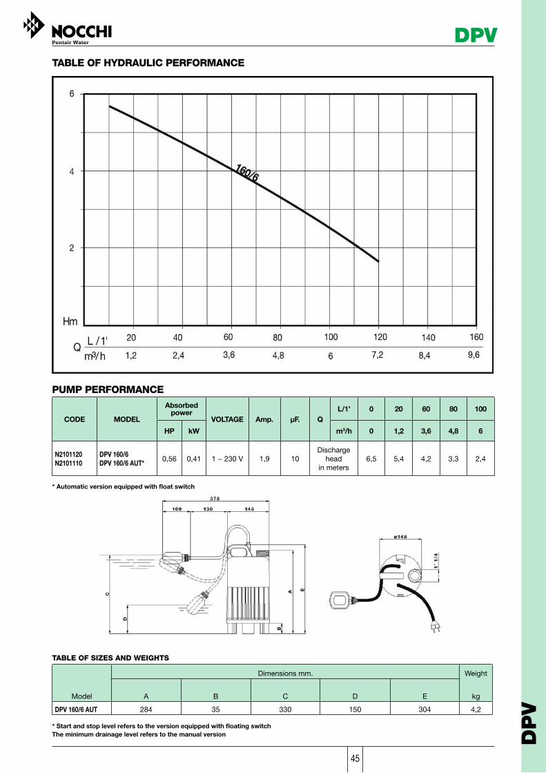
PUMP PERFORMANCE
CODE MODEL
Absorbed power
VOLTAGE Amp. µF. QL/1’ 0 20 60 80 100
HP kW m3/h 0 1,2 3,6 4,8 6
N2101120 N2101110
DPV 160/6 DPV 160/6 AUT* 0,56 0,41 1 ~ 230 V 1,9 10
Discharge head
in meters 6,5 5,4 4,2 3,3 2,4
* Automatic version equipped with float switch
DPVTABLE OF HYDRAULIC PERFORMANCE
TABLE OF SIZES AND WEIGHTS
Model
Dimensions mm. Weight
A B C D E kg
DPV 160/6 AUT 284 35 330 150 304 4,2
* Start and stop level refers to the version equipped with floating switch The minimum drainage level refers to the manual version D
PV

46
OMNIASUBMERSIBLE SUMP PUMPS FOR DIRTY WATER
The OMNIA series pumps are made entirely of AISI 304 stainless steel. Cooling of the motor is via a heat exchange chamber that allows the machine to work for long periods when not completely submerged. Equipped with Ø 32mm hose adapter. Automatic version equipped with float switch.
Applications - Pumping of domestic waste water, draining of environments, bathing and swimming pools, industrial applications - Fountains and water features - Surface irrigation
Motor - Dry motor with stainless steel casing - Level of protection IP68 - Class F insulation - Single phase power supply with capacitor permanently activated - Thermal protection built into the motor winding - Completely insulated cable connection chamber - Self-Iubricating ball bearings - Speed of rotation 2850 rpm
Usage limitations- Type of liquid: waste water with solids - Maximum liquid temperature 40°C - Maximum submersion under the water level 7m - Minimum drainage level 35 mm (manual) - Free clearance of solids 20 mm
DESIGN FEATURES
Component Material
1 Pump body X 5 CrNi 1810 (AISI 304) Stainless steel
2 Suction base X 5 CrNi 1810 (AISI 304) Stainless steel
3 Impeller X 5 CrNi 1810 (AISI 304) Stainless steel 4 Power cable 10m H07 RN-F with plug
5 Motor shaft X 12 CrNiS 1809 (AISI 416) Stainless steel
6 Seal Fixed double NBR 70 rubber lip seal. Oil chamber for seallubrication.
7 Outlet 1” 1/4 gas male threaded

47
OMNIATABLE OF HYDRAULIC PERFORMANCE
PUMP PERFORMANCE
CODE MODEL
Nominal power
Absorbed power
VOLTAGE Amp. µF. Q L/1’ 10 40 70 100 140 200
HP kW HP kW m3/h 0,6 2,4 4,2 6 8,4 12
N2081070 N2081 090
OMNIA 80/5 OMNIA 80/5 AUT T 0,3 0,2 0,4 0,3
1 ~ 230 ÷ 240 V
1,4 8
Dis
char
ge
head
in
met
ers
4,1 2,7 1
N2081020 N2081110
OMNIA 160/7 OMNIA 160/7 AUT 0,5 0,37 0,7 0,5
1 ~ 230 ÷ 240 V
2,5 8 7 5,5 4 2,8 1
N2081030 N2081100
OMNIA 200/8 OMNIA 200/8 AUT 0,7 0,5 1 0,75
1 ~ 230 ÷ 240 V
3,2 8 7,8 6,3 5,4 4,1 2,7 0,5
TABLE OF SIZES AND WEIGHTS
Model
Dimensions mm. Weight
Minimum drainage level Start level Stop level Free bore
A B Ø C D E* F* G* DNM kg
OMNIA 80/5 264 94 177 182 35 250 100 020 1” 1/4 6,1
OMNIA 160/7 300 94 177 182 35 320 107 020 1” 1/4 7
OMNIA 200/8 338 94 177 182 35 351 111 020 1” 1/4 8,5
* Start and stop level refer to the version equipped with float switch. The minimum drainage level refers to manual working. O
MN
IA

48
BIOX XS
Motor- Dry motor- Level of protection IP 68- Class F insulation- Single phase power supply 230 V +- 10% 50 Hz with capacitor permanently activated and thermal protection built into the motor winding- Completely insulated cable connection chamber- Self-lubricating ball bearings- Speed of rotation 2850 rpm
SUBMERSIBLE EFFLUENT VORTEX PUMPSFOR DIRTY WATER
The BIOX XS series pumps are made entirely of AISI 304 stainless steel.They work completely submerged in the pumped liquid that cools the motor externally.Manufactured on the vortex operating principle with the impeller set back.Automatic version equipped with float switch.
• SILICUM CARBIDE/SILICUM CARBIDE MECHANICAL SEAL
Applications- All applications of pumping and draining sewage with suspended solids- Pumping stations with one or more pumps for civil and rural plants- suitable for emptying of seepage water, handling of waste water (sanitary water), emptying of cesspit and draining of sewage systems
Usage limitation- Type of liquid: waste water and sewage with solids- Maximum liquid temperature 40°C.- Maximun submersion under the water level 7m- Free clearance of solids: 40 mm
DESIGN FEATURES
Components Material1 Pump body X 5 CrNi 1810 (AISI 304) Stainless steel
2 Suction base X 5 CrNi 1810 (AISI 304) Stainless steel
3 Impeller X 5 CrNi 1810 (AISI 304) Cast stainless steel
4 Outlet Threaded
5 Power cable 10m HO7 RN-F with plug 6 Motor shaft X 12 CrNiS 1809 (AISI 416) Stainless steel
7 Mechanical seal Silicum carbide Silicum carbide
8 Counterface Silicum carbide Oil chamber forseal lubrication9 Secondary seal NBR rubber lip seal
10 V-ring sand guard NBR rubber

49
BIOX XSTABLE OF HYDRAULIC PERFORMANCE
PUMP PERFORMANCE
CODE MODEL P2 (out) P1 (in)
VOLTAGE InA µF. Q
L/1’ 50 100 150 200 250 300 350
HP kW HP kW m3/h 3 6 9 9 12 15 18
N2091190N2091200
BIOX 250/9 XS AUTBIOX 350/10 XS AUT
0,8 0,6 1,2 0,9 1 ~ 230 4,1 12,5
Disc
harg
e he
ad
in m
eter
s 8 6,6 5,1 3,4 1,6
1,2 0,9 1,7 1,3 1 ~ 230 5,8 20 9,6 8,5 7,3 6 4,5 3 1,5
ModelDimensions mm. Weight
A B C Ø D DNM H1 H2 kg
BIOX 250/9 XS AUT 389 196 96 168 1”1/2 GAS 250 370 9,8
BIOX 350/10 XS AUT 419 196 96 168 2” GAS 300 400 11,2
TABLE OF SIZES AND WEIGHTS
BIO
X X
S

50
PRIOXSUBMERSIBLE EFFLUENT VORTEX PUMPS FORDIRTY WATER
The PRIOX series pumps are made entirely of AISI 304 stainless steel. They workcompletely submerged in the pumped liquid that cools the motor externally.Manufactured on the vortex operating principle with the impeller set back. Automatic version equipped with float switch.
Applications - All applications of pumping and draining effluent, civil and industrial sewage with suspended solids- Pumping stations with one or more pumps for civil and industrial plants
Motor - Dry motor - Level of protection I P 68 - Class F insulation - Single phase power supply with capacitor permanently activated and thermal protection built into the motor winding - Three phase power supply with external protection under care of the user (control panel on request)- Completely insulated cable connection chamber - Self-lubricating ball bearings - Speed of rotation 2850 rpm
Usage limitations - Type of liquid: waste water and sewage with solids - Maximum liquid temperature 40°C. - Maximun submersion under the water level 7m - Minimum drainage level 60 mm (manual version) - Free clearance of solids: 40 mm 50mm (PRIOX 600/13 - PRIOX 800/18)
Component Material
1 Pump body X 5 CrNi 1810 (AISI 304) Stainless steel
2 Suction base X 5 CrNi 1810 (AISI 304) Stainless steel
3 Impeller X 5 CrNi 1810 (AISI 304) Cast stainless steel
4 Outlet Threaded
5 Cover Cast stainless steel (Priox 800/18)
6 Power cable 10m HOl RN-F with plug
7 Motor shaft X 12 CrNiS 1809 (AISI 416) Stainless steel
8 Mechanical seal Silicum carbide
9 Counterface Silicum carbide Oil chamber for seal lubrication 10 Secondary seal NBR rubber lip seal
11 V-ring sand guard NBR rubber
DESIGN FEATURES
1
2
3
6
7
8
9
4
1011
5

51
PRIOX
TABLE OF HYDRAULIC PERFORMANCE
CODE MODEL
Nominal power
Absorbed power
VOLTAGE
Amp. µF. Q L/1’ 50 100 150 200 250 300 400 500 550 600 650
HP kW HP kW m3/h 3 6 9 12 15 18 24 30 33 36 39
N2110100 PRIOX 250/8 M 0,75 0,55 1,1 0,8 1 ~ 230 V 3,6 14
Dis
char
ge h
ead
in
met
ers
6,5 5,2 3,4 2,0 0,2 N2110110 PRIOX 250/8 M AUT N2110040 PRIOX 300/9 M
0,8 0,6 1,2 0,9 1 ~ 230 V 4,1 14 7,7 6,4 5 3,8 2,3 1 N2110050 PRIOX 300/9 M AUT
N2110090 PRIOX 300/9 T 0,8 0,6 1,2 0,9 3 ~ 400 V 1,55 7,7 6,4 5 3,8 2,3 1
N2110020 PRIOX 420/11 M 1,2 0,9 1,8 1,3 1 ~ 230 V 6 20
10 9 7,8 6,3 5 3,8 1 N2110030 PRIOX 420/11 M AUT N2110080 PRIOX 420/11 T 1,2 0,9 1,8 1,3 3 ~ 400 V 2,3
N2110000 PRIOX 460/13 M 1,5 1,1 2,2 1,6 1 ~ 230 V 7,5 20
11,8 10,8 9,8 8,5 7 5,5 2 N2110010 PRIOX 460/13 M AUT
N2110070 PRIOX 460/13 T 1,4 1 2 1,45 3 ~ 400 V 2,7
N2110060 PRIOX 600/13 T 1,6 1,2 2,4 1,8 3 ~ 400 V 3 12,8 12,2 11,3 10,3 9,3 8 5,5 3 1,8
N2110130 PRIOX 800/18 T 3,2 2,4 4 3 3 ~ 400 V 5,5 17,3 16,5 15,6 14,7 13,7 12,7 10,5 8 6,7 5,4 4
PUMP PERFORMANCE
500100 6002006 12 30 36
30018
40024
14
12
6
4
2
8
10
m3/ hL / 1'Q
Hm
16
18
20
800/18
600/13460/13420/11300/9250/8
70042
* Start and stop level refer to the version equipped with float switch. The minimum drainage level refers to manual working.
TABLE OF SIZES AND WEIGHTS
Model
Dimensions mm.
PRIOX 460/13
PRIOX 420/11
PRIOX 300/9
PRIOX 600/13
PRIOX 250/8
PRIOX 800/18 T
A
420
450
450
450
420
485,5
B
122,5
122,5
122,5
122,5
122,5
122,5
Ø C
235
235
235
235
235
235
D
241
241
241
241
241
241
Minimumdrainage
levelE*
63
63
63
63
63
63
Startlevel
F*
550
580
580
550
580
Stoplevel
G*
290
320
320
290
320
Freebore
Ø 40
Ø 40
Ø 40
Ø 50
Ø 40
Ø 50
DNM
2"
2"
2"
2"
1"1/2
2"
Weight
kg
9,6
11,2
11,7
12,6
9,4
20,2* Start and stop level refer to the version equipped with float switch. The minimum drainage level refers to manual working.
TABLE OF SIZES AND WEIGHTS
Model
Dimensions mm.
PRIOX 460/13
PRIOX 420/11
PRIOX 300/9
PRIOX 600/13
PRIOX 250/8
PRIOX 800/18 T
A
420
450
450
450
420
485,5
B
122,5
122,5
122,5
122,5
122,5
122,5
Ø C
235
235
235
235
235
235
D
241
241
241
241
241
241
Minimumdrainage
levelE*
63
63
63
63
63
63
Startlevel
F*
550
580
580
550
580
Stoplevel
G*
290
320
320
290
320
Freebore
Ø 40
Ø 40
Ø 40
Ø 50
Ø 40
Ø 50
DNM
2"
2"
2"
2"
1"1/2
2"
Weight
kg
9,6
11,2
11,7
12,6
9,4
20,2
* Start and stop level refer to the version equipped with float switch. The minimum drainage level refers to manual working.
TABLE OF SIZES AND WEIGHTS
Model
Dimensions mm.
PRIOX 460/13
PRIOX 420/11
PRIOX 300/9
PRIOX 600/13
PRIOX 250/8
PRIOX 800/18 T
A
420
450
450
450
420
485,5
B
122,5
122,5
122,5
122,5
122,5
122,5
Ø C
235
235
235
235
235
235
D
241
241
241
241
241
241
Minimumdrainage
levelE*
63
63
63
63
63
63
Startlevel
F*
550
580
580
550
580
Stoplevel
G*
290
320
320
290
320
Freebore
Ø 40
Ø 40
Ø 40
Ø 50
Ø 40
Ø 50
DNM
2"
2"
2"
2"
1"1/2
2"
Weight
kg
9,6
11,2
11,7
12,6
9,4
20,2
PR
IOX

52
MINIVORT PSUBMERSIBLE SEWAGE PUMPS WITH VORTEX IMPELLER
The MINIVORT P pumps are made entirely of cast iron and designed for continuoususe in fixed installations. Manufactured on the vortex operating principle with theimpeller set back.Strong and resistant.
Motor- Dry motor- Level of protection IP68- Class F insulation- Single phase power supply with capacitor permanently activated and thermal protection built into the motor winding- Three phase power supply with external protection provided by the user- Self-lubricating ball bearings- Speed of rotation 2850 rpm- Four pole 1450 rpm (P2) motor (P4).
Applications- Pumping and draining effluent; civil and industrial sewage with suspended solids- Draining of cesspits, cesspools, handling of effluent- Pumping stations with one or more pumps for civil and industrial plants
Usage limitations- Type of liquid: waste water and sewage- Maximum liquid temperature 40°C- Maximum submersion under the water level 7m- Minimum drainage level 45mm (manual version)- Free clearance of solids 52 mm
Impeller
Pump body
Motor shaft
Mechanical sealCounterface
EN GJL 200 (ex G20) Grey cast iron
X 12 CrNiS 1809 (AISI 416) Stainless steel
Oil chamber for seal lubricationCeramic
Motor casing EN GJL 200 (ex G20) Grey cast iron
Base EN GJL 200 (ex G20) Grey cast iron
EN GJL 200 (ex G20) Grey cast iron
Component Material
DESIGN FEATURES
Design features- Automatic single phase version with float switch and sealed electric panel including capacitor, thermal protection and manual/automatic switch. 10 m H07 RN-F power supply cable- Three phase version, 10 m H07 RN-F power supply cable- Flanged outlet connection, with square threaded counterflange - 2" female
Lip seal NBR 70 rubber

53
MINIVORT P
MIN
IVO
RT P
TABLE OF HYDRAULIC PERFORMANCE
TABLE OF SIZES AND WEIGHTS
ModelDimensions mm.
A
Weight
C kg
PUMP PERFORMANCE
MODELCODE
Absorbedpower
kWVOLTAGE Amp. µF. Q
L/1'
m3/h
50Nominalpower
HP 3
300
18
400
24
100
6
200
12kW HP
500
30
B
A D
C
DN
M
L / 1'm3/ h
Q
Hm
500100 6002006 12 30 36
30018
40024
70042
14
12
6
4
2
8
10P2 - 2
P2 - 1,5P2 - 1
1 ~ 220 ÷ 240 V1 ~ 220 ÷ 240 V
3 ~ 400 V
MINIVORT P2 - 1 M MINIVORT P2 - 1 M AUT MINIVORT P2 - 1 T
N2041010 N2041020 N2041030
2 1,5 6 5,41 0,75
MINIVORT P2 - 1,5 M MINIVORT P2 - 1,5 M AUT MINIVORT P2 - 1,5 T
N2042010 N2042020 N2042030
2,2 1,6 8,3 7,51,5 1,1
MINIVORT P2 - 2 M MINIVORT P2 - 2 M AUT MINIVORT P2 - 2 T
N2043010 N2043020 N2043030
3 2,2 12,1 11,32 1,5
1 ~ 220 ÷ 240 V1 ~ 220 ÷ 240 V
3 ~ 400 V1 ~ 220 ÷ 240 V1 ~ 220 ÷ 240 V
3 ~ 400 V
4,1 3 1
6,1 4,6 2,8 1
9,8 8 6 3,7
6,56,52,3
77
2,79,89,83,2
2020
2525
3535
P4 - 1
B D DNM
MINIVORT P2 - 2
MINIVORT P2 - 1,5
MINIVORT P2 - 1 45
45
45
27
27
28
440
440
440
85
85
85
235
235
235
2"
2"
2"
MINIVORT P4 - 1 45 27440 85 235 2"
MINIVORT P4 - 1 M MINIVORT P4 - 1 M AUT MINIVORT P4 - 1 T
N2044010 N2044020 N2044030
1,7 1,25 5 4,61 0,751 ~ 220 ÷ 240 V1 ~ 220 ÷ 240 V
3 ~ 400 V3,3 2,2
5,55,52,3
2525
MINIVORT P2 : 2 poles motor 2850 rpmMINIVORT P4 : 4 poles motor 1450 rpm
Dis
char
ge h
ead
in m
eter
s

54
SUBMERSIBLE SEWAGE PUMPS WITH VORTEX IMPELLER
The MINIVORT PP pumps are made entirely of cast iron and designed for continuoususe in fixed installations. Manufactured on the vortex operating principle with theimpeller set back.
Motor- Dry motor- Level of protection IP68- Class F insulation- Single phase power supply with capacitor permanently activated and thermal protection built into the motor winding- Three phase power supply with external protection provided by the user- Self-lubricating ball bearings- Speed of rotation 2850 rpm
Applications- Pumping and draining effluent; civil and industrial sewage with suspended solids- Draining of cesspits, cesspools, handling of effluent- Pumping stations with one or more pumps for civil and industrial plants- On request, connecting foot to make installations and maintenance easier
Usage limitations- Type of liquid: waste water and sewage- Maximum liquid temperature 40°C- Maximum submersion under the water level 7m- Minimum drainage level 72mm (manual version)- Free clearance of solids 58 mm
Design features- Automatic single phase version with float switch and sealed electric panel including capacitor, thermal protection and manual/automatic switch. 10 m H07 RN-F power supply cable- Three phase version, 10 m H07 RN-F power supply cable- Single phase version with panel complete with capacitor and 10 m H07 RN-F power supply cable- Flanged outlet connection, with square threaded counterflange - 2" female
Impeller
Pump casing
Motor shaft
Mechanical sealCounterface
EN GJL 200 (ex G20) Grey cast iron
X 12 CrNiS 1809 (AISI 416) Stainless steel
Oil chamber for seal lubricationCeramic
Motor casing EN GJL 200 (ex G20) Grey cast iron
Base EN GJL 200 (ex G20) Grey cast iron
EN GJL 200 (ex G20) Grey cast iron
Power cable 10 m H07 RN-F
Component Material
DESIGN FEATURES
12
3
45
6
78
1
2
3
4
6
5
7
8
OptionalCast iron connecting foot( cod. N2054010 )
Lip seal NBR 70 rubber-
Graphite
MINIVORT PP

55
TABLE OF HYDRAULIC PERFORMANCE
TABLE OF SIZES AND WEIGHTS
PUMP PERFORMANCE
MODELCODE
Absorbedpower
kWVOLTAGE Amp. µF. Q
L/1'
m3/h
100Nominalpower
HP 6
400
24
600
36
200
12
300
18kW HP
800
48
B
A
D
CD
NM
L / 1'm3/ h
Q
Hm
PP2 - 1
500100 6002006
300 400 700
12
10
8
6
2
48 54800 900
4
12 30 3618 24 42
PP2 - 1,5
PP2 - 2
MINIVORT PP2 - 2
MINIVORT PP2 - 1,5
MINIVORT PP2 - 1 72
72
72
30
31
33
475
475
475
115
115
115
325
325
325
2 1/2"
2 1/2"
2 1/2"
1 ~ 220 ÷ 240 V1 ~ 220 ÷ 240 V
3 ~ 400 V
MINIVORT PP2 - 1 M MINIVORT PP2 - 1 M AUT MINIVORT PP2 - 1 T
N2051010 N2051020 N2051030
2 1,5 5 41 0,75
MINIVORT PP2 - 1,5 M MINIVORT PP2 - 1,5 M AUT MINIVORT PP2 - 1,5 T
N2052010 N2052020 N2052030
1,8 6,7 5,7
MINIVORT PP2 - 2 M MINIVORT PP2 - 2 M AUT MINIVORT PP2 - 2 T
N2053010 N2053020 N2053030
3 2,2 10 9,32 1,5
1 ~ 220 ÷ 240 V1 ~ 220 ÷ 240 V
3 ~ 400 V1 ~ 220 ÷ 240 V1 ~ 220 ÷ 240 V
3 ~ 400 V
3
4,6 3,3 1
8,2 7 4,2 1
6,26,22,38,28,23
9,89,83,5
2020
2525
3535
1,6
1,6 1,2 2,5
ModelDimensions mm.
A
Weight
C kgB D DNM
MINIVORT PP
MIN
IVO
RT P
P

56
COLLECTION AND PUMPING STATIONS FORDIRTY WATER
The VACUSYSTEM 200 are pre-assembled ready-for-use automatic pumping stations.Particularly suitable when the water from drains is collected at a lower level than themain sewer.The standard pumping station consists of PRIOX submersible pump.
Electric pump motor- Dry motor- Level of protection IP68- Class F insulation- Single phase power supply with capacitor permanently activated and thermal protection built into the motor winding- Completely insulated cable connection chamber- Speed of rotation 2850 rpm- Self lubricating ball bearings
Usage limitations- Type of liquid: water with suspended solids of a maximum dimension of 40 mm- Maximum liquid temperature 40°C- Minimum drainage level 60 mm
Design features
The standard pumping station consists of:- Tank in polyethylene with a capacity of 175 l. The closing lid is supplied with O-ring. It warrants liquid seal and possible gas locks.- DN 110 inlet, 2” outlet and DN 50 vent connection- PRIOX 300/9 AUT, PRIOX 460/13 M AUT submersible pump
Oil chamber forseal lubrication
Component
Impeller
Pump casing
Motor shaft
Mechanical seal
Counterface
Material
X 5 CrNi 1810 (AISI 304) Stainless steel
X 12 CrNi 1809 (AISI 416) Stainless steel
Silicon carbide
Silicon carbide
PRIOX DESIGN FEATURES
Suction base X 5 CrNi 1810 (AISI 304) Stainless steel
X 5 CrNi 1810 (AISI 304) Cast stainless steel
Power cable 10 m H07 RN-F
Secondary seal NBR rubber lip seal
V-ring sand protection NBR rubber
VACUSYSTEM

57
VACUSYSTEM
VA
CU
SYSTE
M
TABLE OF HYDRAULIC PERFORMANCE
VACUSYSTEM
DIMENSIONS AND WEIGHTS
27500
A
380
B
250
C
100
D
185
E
250
F
130
G H
410 350
I
800
L
410
M
350
N
635
O
515
P
720
Q
185
R
85
S
29,2500 380 250 100 185 250 130 410 350 800 410 350 635 515 720 185 85
VS 200 - P 300 M
VS 200 - P 460 M
Weight Model
Dimensions mm.
kg
PUMP PERFORMANCE
MODELCODE
Absorbedpower
kWVOLTAGE Amp. µF. Q
L/1'
m3/h
50Nominalpower
HP
Dis
char
ge h
ead
in m
eter
s
3
200
12
250
15
100
6
150
9kW HP
300
18
400
24
1 ~ 230 VVS 200 - P 300 M N2141140
1 ~ 230 VVS 200 - P 460 M N2141150 10,8 9,8 8,5 7 5,5 2
4,1
7,2
12,5
20
6,4 5 3,8 2,3 10,8
1,4
0,6
1
1,2
2,2
0,9
1,6 11,8
7,7
L / 1'm3/ h
Q
Hm
300/9
460/13
500100 6002006 12 30 36
30018
40024
14
12
6
4
2
8
10

58
COLLECTION AND PUMPING STATIONS FORDIRTY WATER
The VACUSYSTEM 200S are pre-assembled ready-for-use automatic pumping stations.Particularly suitable when the water from drains is collected at a lower level than themain sewer.The standard pumping station consists of PRIOX submersible pump.
• CONNECTING FOOTElectric pump motor
- Dry motor- Level of protection IP68- Class F insulation- Single-phase power supply with capacitor permanently activated and thermal protection built into the motor winding- Completely insulated cable connection chamber- Self lubricating ball bearings- Speed of rotation 2850 rpm
Usage limitations- Type of liquid: water with suspended solids of a maximum dimension of 40 mm- Maximum liquid temperature 40°C- Minimum drainage level 60 mm
Design features
- The standard pumping station consists of:
- Tank in polyethylene with a capacity of 175 l. The closing lid is supplied with O-ring. It warrants liquid seal and possible gas locks.- DN 110 inlet, 2” outlet and DN 50 vent connection- Connecting foot- Electric panel for the control and protection of three-phase electric pumps.- Float switch with 10 m of 2 x 1 H07 RN-F cable (for three-phase pumps)- PRIOX Submersible Pump Models:- Priox 300/9 M AUT, Priox 300/9 T- Priox 460/13 M AUT, Priox 460/13 T
Oil chamber forseal lubrication
Component
Impeller
Pump casing
Motor shaft
Mechanical seal
Counterface
Material
X 5 CrNi 1810 (AISI 304) Stainless steel
X 12 CrNi 1809 (AISI 416) Stainless steel
Silicon carbide
Silicon carbide
PRIOX DESIGN FEATURES
Suction base X 5 CrNi 1810 (AISI 304) Stainless steel
X 5 CrNi 1810 (AISI 304) Cast stainless steel
Power cable 10 m H07 RN-F
Secondary seal NBR rubber lip seal
V-ring sand protection NBR rubber
VACUSYSTEM

59
VACUSYSTEM
VA
CU
SYSTE
M

60
VACUSYSTEM
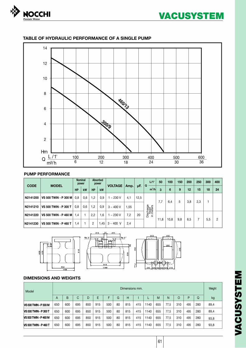
61
VACUSYSTEM
VA
CU
SYSTE
M

62
SUBMERSIBLE PUMPS FOR FOUNTAINS ANDWATER FEATURES
The VERSAILLES pumps have been designed for fountains, water features and waterfallsin water gardens.
Motor- Dry motor with stainless steel casing- Level of protection IP68- Class F insulation- Single phase power supply with capacitor permanently activated- Thermal protection built into the motor winding- Completely insulated cable connection chamber- Self-lubricating ball bearings- Speed of rotation 2850 rpm- Suitable for continuous use
Usage limitations- Type of liquid: clear water, free of solids- Maximum liquid temperature 40°C- Maximum submersion under the water level 7m- Free clearance: 1,5mm. For water features with a less clearance insert the sponge filter (optional) in the hydraulics
Applications- For fountains, water features, waterfalls in water gardens
Component
Suction grid
Base
Impeller
Power cable
Seal
Motor shaft
Material
X 5 CrNi 1810 (AISI 304) Stainless steel
X 5 CrNi 1810 (AISI 304) Stainless steel
10 m H07 RN-F With plug
DESIGN FEATURES
Pump casing
Fixed double NBR 70 rubber sealwith special sand guard V-ring
X 12 CrS 13 (AISI 416) Withceramic facing at the points of wear
X 5 CrNi 1810 (AISI 304) Stainless steel
X 5 CrNi 1810 (AISI 304) Die cast stainless steel
1” F reducer Plastic
SPARE FILTER
Accessories (optional)- Vulcano: adjustable water feature with three level jets- Gaiser: adjustable water feature with a single foamy jet- Campana: adjustable bell-shaped water feature- Filters: sponge to be used for water features with clearances under 1.5 mm
VERSAILLES
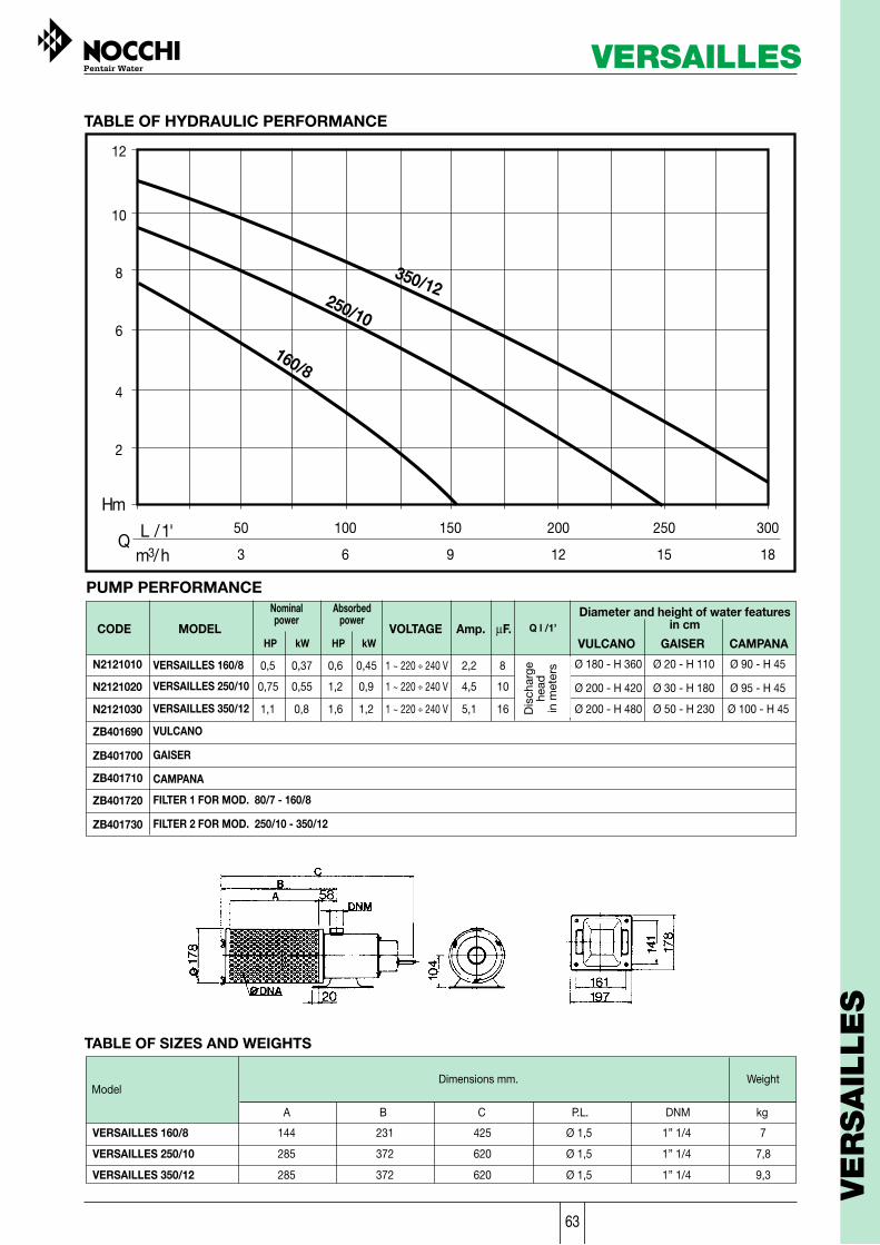
63
VERSAILLES
VE
RSA
ILLE
S
TABLE OF HYDRAULIC PERFORMANCE
PUMP PERFORMANCE
MODELCODE
Absorbedpower
kWVOLTAGE Amp. µF. Q l /1’
HP kW HP
Nominalpower
TABLE OF SIZES AND WEIGHTS
ModelDimensions mm.
A
Weight
B C DNM kgP.L.
VERSAILLES 160/8
VERSAILLES 250/10
144
285
231
372
425
620
Ø 1,5
Ø 1,5
1” 1/4
1” 1/4
7
7,8
VERSAILLES 350/12 285 372 620 Ø 1,5 1” 1/4 9,3
N2121010
N2121020
N2121030
ZB401690
ZB401700
ZB401710
ZB401720
ZB401730
VERSAILLES 160/8
VERSAILLES 250/10
VERSAILLES 350/12
VULCANO
GAISER
CAMPANA
FILTER 1 FOR MOD. 80/7 - 160/8
FILTER 2 FOR MOD. 250/10 - 350/12
Diameter and height of water featuresin cm
VULCANO GAISER CAMPANA
0,6 0,450,5 0,37
1,2 0,90,75 0,55
1,6 1,21,1 0,8
1 ~ 220 ÷ 240 V
1 ~ 220 ÷ 240 V
1 ~ 220 ÷ 240 V
2,2
4,5
5,1
8
10
16
Ø 180 - H 360
Ø 200 - H 420
Ø 200 - H 480
Ø 20 - H 110
Ø 30 - H 180
Ø 50 - H 230
Ø 90 - H 45
Ø 95 - H 45
Ø 100 - H 45
Hm
12
L / 1'm3/ h
Q 50 100 150 200 250 300
3 6 9 12 15 18
10
8
6
4
2
350/12
160/8
250/10
Dis
char
gehe
adin
met
ers

64
CAMPANA
GAISER
VULCANO
VERSAILLES

65
55
75
112
153
178
235
328
WM0060
WM0075
WM0120
WM0150
WM0180
WM0235
WM0330
453
606
757
1022
WM0450
WM0600
WM-IN-750
WM-IN-1000
Note: Maximum external operating temperature 120°F (49°C). Maximum internal operating temperature 100°F (38°C). Minimum operating temperature 40°F (4°C).* With minimum and maximum system pressure between 2,0 and 3,5 bar
*Diameter, height and weight may vary slightly without notice.
TECHNICAL FEATURES
VOLUMElt
CODE
18,3
25
37,3
50,9
59,3
78,3
109,2
150,8
201,8
252,1
340,3
8,5
8,5
8,5
8,5
8,5
8,5
8,5
8,5
10
10
10
1” M NPT
1” M NPT
1” M NPT
1” M NPT
1”1/4 M NPT
1”1/4 M NPT
1”1/4 M NPT
1”1/4 M NPT
2” M BSP
2” M BSP
2” M BSP
WM0060
WM0075
WM0120
WM0150
WM0180
WM0235
WM0330
WM0450
WM0600
WM-IN-750
WM-IN-1000
41
41
41
53
61
61
61
76
76
92
WM0060 41
81
112
145
105
105
140
189
174
206
212
66
4,4
4,4
4,4
5,7
5,7
5,7
5,7
15
15
20
4,4
8,1
11,2
13,6
19,5
22,7
33,0
43,1
76,2
89,0
117,1
6,6
254
CODE MODELWM-PB-001 PUMP BASEMENT
Wellmate tanks in composite material represent the best solution for pressurized water storage and pressureboostingapplications. Thanks to the high density polyethylene inner liner and to the fiberglass-wound and epoxy resin-sealed outershell, Wellmate tanks don't rust,require little maintenance and weigh half then an equivalent steel tank. All Wellmate vesselsare tested and certified by NSF International and produced according to the European Pressure Equipment Directive (PED)97/23/EC.
height* Outlet height to floor*Diameter*
TABLE OF SIZES AND WEIGHTS
CODE
Dimension (cm)weight*
Kg
REAL WATERVOLUME
(DRAWDOWN SETTING)*
MAXIMUMOPERATING
PRESSURE (BAR)CONNECTIONS
IN COMPOSITE MATERIALWELLMATE TANKS
WE
LLM
ATE
TA
NK
S

66
EXPANSION TANKS
UPRIGHT VERSIONInterchangeable bromobutyl diaphragm,and capacities of 8-20-24 litres.The latter version is also available withoutdiaphragm with an air feeder.Preload: 1,5 bar
HORIZONTAL VERSION24- litres diaphragm with assemblybracket for the electric pump and a newsupport foot, designed to ensuremaximum stability.Preload: 1,5 bar
71
EXPANSION TANKS
VES INOX N 8
VES INOX N 20
VES INOX N 24
VES INOX N 24 H
VAA 24
-
ZA006450
ZA006460
ZA006570
ZA006470
ZA006610
ZA007000
PERFORMANCE
MODELCODE
EX
PA
NSIO
N T
AN
KS
STAINLESS STEEL
N 8
N 20
N 24
N 24 H
VAA 24
280 226 1”- 2,4
390 272 1”- 3,3
430 272 1”- 5,0
430 272 1”300 4,2
430 272 1”443 4,2
Ø B C DA
TABLE OF SIZES AND WEIGHTS
ModelDimensions mm. Weight
Kg
DESCRIPTION DIAPHRAGM Assemblybracket
Max. operatingpreassure
( bar )
CapacityLt
VERTICAL 8 LT STAINLESS STEEL EXPANSION TANK
VERTICAL 20 LT STAINLESS STEEL EXPANSION TANK
VERTICAL 24 LT STAINLESS STEEL EXPANSION TANK
HORIZONTAL 24 LT STAINLESS STEEL EXPANSION TANK
24 LITRE STAINLESS STEEL TANK FOR AIR FEEDER
AIR FEEDER WITH FLEXIBLE PIPE
BROMOBUTYL
BROMOBUTYL
BROMOBUTYL
BROMOBUTYL
-
-
-
-
-
-
YES
-
8
8
8
8
8
-
8
20
24
24
24
-
Ø B
A
A
C Ø B
A
Ø B
DD
D
NOCCHI expansion tanks are made of AISI 304 stainless steel and are available in several models that are able to meet all thedemand of civil and industrial plants.No toxic replaceable bladder suitable for food use, particularly recommended for use in humid environments.In compliance with EC standards.

67
EXPANSION TANKS
EX
PA
NSIO
N T
AN
KS
EXPANSION TANKS
72
VES 2
VES 24 V
VES 24 H
ZA003860
ZA000140
ZA003850
PUMP PERFORMANCE
MODELCODE
PAINTED STEEL
DESCRIPTION DIAPHRAGM Assemblybracket
6
6
6
2
24
24
-
-
YES
Ø B DCA
TABLE OF SIZES AND WEIGHTS
ModelDimensions mm. Kg
415
VES 2
VES 24 V
VES 24 H
155
-
1” M
1” M
1” M
-
-
310415
175
295
845
950
VEC 60 V
VEC 100 V
VEC 200 V
VEC 300 V
VEC 500 V
1225
1405
1550
1” M
1” M
1” 1/2 M
1” 1/2 M
1” 1/2 M
-
-
-
-
-
382
450
550
630
780
17,5
19
37
54
104
4,1
0,950
4,8
A
Ø B
D
A
C Ø BD
A
Ø B
Max. operatingpressure
( bar )
CapacityLt
2 LITER EXPANSION TANK
VERTICAL 24 LITER EXPANSION TANK
HORIZONTAL 24 LITER EXPANSION TANK
Food - quality rubber
Food - quality rubber
Food - quality rubber
VEC 60 VZA009070-CE 10 60VERTICAL 60 LITER EXPANSION TANK Butyl rubber YES
VEC 100 VZA009080-CE
ZA009090-CE
ZA009100-CE
ZA009110-CE
VEC 200 V
VEC 300 V
VEC 500 V
VERTICAL 100 LITER EXPANSION TANK
VERTICAL 200 LITER EXPANSION TANK
VERTICAL 300 LITER EXPANSION TANK
VERTICAL 500 LITER EXPANSION TANK
Butyl rubber
Butyl rubber
Butyl rubber
Butyl rubber
10 100
200
300
500
10
10
10
YES
YES
YES
YES
Expansion tank for pressure assemblies, in painted steel, from 2 to 500 Lt.,with interchangeable diaphragm.Stainless steel painted carbon flange. CE certificate.Preload: 1.5 bar for models from 2 to 24 Lt. 2.0 bar for models from 60 to 500 Lt.In compliance with EC standards

68 73
FLUSSCONTROL WITH CABLE
FLUSSCONTROL BASICZB902310
Flusscontrol Flusscontrol basicTechnical details
FLUSSCONTROL - F. BASIC

69
SINGLE PHASE STARTER FOR THE CONTROL AND PROTECTION OF SUBMERGEDELECTRIC PUMPS, DIRECT START
Type of functioning- Manual through general switch- Automatic through external remote control (manostat, float…)
Main components- IP55 plastic box- Main switch with circuit breaker and motor- Protector with restart button- Capacitor.- Terminal board- Cable gland
Technical features- Protection level : IP55- Power supply voltage : 230V/ 1F 50 Hz- External dimensions : 115 - 185 - 65 mm- Weight : Kg 0,6
Connection plan
230 1F230 1F
230 1F
230 1F
0,370,55
0,55
0,75
0,50,75
0,75
1
46
6
7SCM 4” PLUS
SCM 4 HF4” MOTORS
230 1F 0,75 1 7
Suitable PumpsMODELCODE
V Kw Hp A
NominalPower Field µF
1620
25
30
35
Supply Voltage50Hz
230 1F 1,1 1,5 9 40
230 1F 1,5 2 12 50
Limits in use- Environmental temperature : -5 / +40 °C- Relative humidity : 50% at 40°C (without forming of condense)- Standards : EN 60335-1 - EN 60439-1
Optional accessories- Float switch or pressure switch (see accessories table)
UZQ12710UZQ12720
UZQ12730
UZQ12740
UZQ12750
UZQ12930
UZQ12940
QES PLUS 10/37 MQES PLUS 10/55 M
QES PLUS 10/75 M
QES PLUS 10/110 M
QES PLUS 10/150 M
QES PLUS 10/55 M
QES PLUS 10/75 M
QES PLUS
CO
NTR
OL P
AN
ELS

70
THREE PHASE ELECTRIC PANEL FOR THE PROTECTION AND CONTROL OFSUBMERSIBLE OR SURFACE ELECTRIC PUMPS, DIRECT START
Connection plan
74
Main components- Plastic enclosure- Dry running protection through float switch,
pressure switch or probes- Power indicator lights
Technical features- Power supply voltage : 3x400 V- Frequency: 50/60 Hz- Power: 0,37 to 7,5 kW.- Direct motor start- Motor protector- Protection level : IP54- External dimensions : 260 - 195 – 180 mm- Weight : Kg 3,35
Type of functioning- Manual through MAN selector
Automatic through external remotecontrol (manostat, float, …) and/orlevel control (filling, emptying, dryfunction protection)
Limits in use- Control through an external
enable contact.- Ambient temperature: -5 to +40 °C
(according to EN 60439-1).- Maximum relative humidity: 50% at
+40°C, provided that no condensationoccurs (according to EN 60439-1).
Optional accessories- ECL electrodes for level control- Float switch or pressure switch
(see accessories table)
Application field
3x400
3x400
3x400
3x400
Volt
3x400
3x400
CODE
UZQ13000
UZQ13010
UZQ13040
UZQ13050
UZQ13020
UZQ13030
P
0,37
0,55
0,75
1,5
2,2
4
kW
min
1
1,6
6,6
10
2,5
4
minA
1,6
2,5
10
16
4
6,3
max
0,55
0,75
1,5
2,2
4
7,5
kWMODEL
Q.EL AT10 1-1,6A 400V
Q.EL AT10 1-2,5A 400V
Q.EL AT10 6,3-10A 400V
Q.EL AT10 10-16A 400V
Q.EL AT10 2,5-4A 400V
Q.EL AT10 4-6,3A 400V
Suitable pumps
Surface Submersible
VLR-VLRI-VLRX
DHR-DHI-MCX
MULTINOX-VE
JET-CM-CB-EP NRM
MULTINOX-MAX
MULTINOX-A
DOMINATOR 5”
SCM 4” PLUS
4” MOTORS
SCM 4 HF
max
AT

71
THREE PHASE STARTER FOR THE CONTROL OF SUBMERGED OR SURFACEELECTRIC PUMPS, DIRECT START
Type of functioning
- Manual through Man. or Aut. Selector- Automatic through external remote control (manostat, float, …) and/or level control (filling, emptying, dry function protection)
Main components- IP 54 painted metallic case.- Main switch, door block- Fuse block with fuses on the main circuit- Fuse block with fuses on the auxiliary circuit- Ammeter with amperometric transformer- Voltmeter with voltmetric selector- Level block light- Function light- Power led- Thermal block light- Terminal board- Contactor 24 V- Overload protection and phase absence thermal relay- Level control module- Transformer for auxiliary circuit- Cable gland- MAN -or -AUT Selector
Technical features- Protection level : IP54- Power supply voltage : 400V/ 3F 50 Hz- External dimensions : 320 - 400 - 180 mm- Weight : Kg 14-50
Suitable PumpsMODELCODE
Kw HpA
min
NominalPower
Field
Surface Submerged
Connection plan
400 3F400 3F400 3F400 3F
5,5
9,2
1115
7,5121520
VLR - VLRIVLRX - NRM
9142028
15233138
SCM4"PLUSSCM4 HF
4"/6" MOTORSSA
UZQ02700UZQ02900UZQ03000UZQ03100
Q.E. AD10/550Q.E. AD10/920Q.E. AD10/1100Q.E. AD10/1500
max
Supply Voltage50Hz
V
Limits in use
- Environmental temp. : -5 / +40 °C- Relative humidity : 50% at 40°C (without forming of condense)- Standards : EN 60730 - EN 60439
Optional accessories- UZA00100 ECL electrodes for level control- CE040010 Panel wall mount fixing fins- Float switch or pressure switch (see accessories table)
AD
CO
NTR
OL P
AN
ELS

72
AYAY/ARTHREE PHASE STARTERS FOR THE CONTROL OF SUBMERGED OR SURFACEELECTRIC PUMPS
Type of functioning- Manual through Man. or Aut. Selector,- Automatic through external remote control (manostat, float, …) and/or level control (filling, emptying, dry function protection)
Main components- IP 54 painted metallic case- Main switch, door block- Fuse block with fuses on the auxiliary circuit- Ammeter with amperometric transformer- Voltmeter with voltmetric selector- Level block light- Function light- Power led- Thermal block light- Terminal board- Overload protection and phase absence thermal relay- Level control module- Transformer for auxiliary circuit- Cable gland- MAN -or -AUT Selector
Technical features- Protection level : IP54- Power supply voltage : 400V/ 3F 50 Hz
Suitable PumpsMODELCODE
Kw HpA
min
NominalPower
Field
maxUZQ03800UZQ03900UZQ04000UZQ04200
Q.E. AY10/400Q.E. AY10/550Q.E. AY10/920Q.E. AY10/1500
UZQ04300UZQ04400UZQ04500UZQ04600
Q.E. AY10/1850Q.E. AY10/2200Q.E. AY10/3000Q.E. AY10/3700
400 3F400 3F400 3F400 3F
45,5
9,2-1115
5,57,5
12-1520
8111625
12162535 VLR - VLRI
VLRX - NRM400 3F400 3F400 3F400 3F
18,522
30-3337
2530
40-4550
34405060
44526282
Surface
Supply Voltage50Hz
V
Limits in use- Environmental temp. : -5 / +40 °C- Relative humidity : 50% at 40°C (without forming of condense)- Standards : EN 60730 - EN 60439
Optional accessories- UZA00100 - ECL electrodes for level control- CE040020 - Panel wall mount fixing fins- Float switch or pressure switch (see accessories table)
AY SERIES- Fuse block with fuses on the main circuit- Timer for S/T exchange- Line – star-triangle contactors- Star/triangle start level control- External dimensions : 400 - 600 - 220 mm- Weight : Kg 25-95
AR
AY
Connection plan

73
SINGLE PHASE STARTERS FOR THE CONTROL OF ONE OR TWO DRAINING ANDSEWAGE ELECTRIC PUMPS
Type of functioning- Manual through general switch.- Automatic through float switch.
Main components- IP 54 metallic case- General switch- Fuse block with fuses for the electric pump- Contactor with thermal relay- Transformer for auxiliary circuit- Fuse block with fuses on the auxiliary circuit- Terminal board with level control devices- Cable gland- Function light- Power led- Thermal block light- Level alarm
ADRM 10
- Electronic signalling, control and command card- For the control of one electric pump- Weight : Kg 5,5
Connection plan
Technical features- Protection level : IP54- Power supply voltage : 220V/240V 1F 50 Hz- External dimensions : 220 x 270 x 185 mm
ADRM 20
- Electronic signalling, control and command card equipped with cyclic startings converter- For the control of two electric pumps- Weight : Kg 7,5
ADRM10
ADRM20
Suitable PumpsMODELCODE
Supply Voltage50Hz
V Kw HpA
min
Nominalpower
Field
230 1F230 1F230 1F
0,550,751,1
0,751
1,5
2,54
6,3
46,310
DRENOX OMNIAPRIOX MINIVORT P
MINIVORT PP
UZQ06500UZQ06700UZQ06800UZQ06900
Q.E. ADRM10/55Q.E. ADRM10/75Q.E. ADRM10/110Q.E. ADRM10/150 230 1F 1,5 2 10 16
230 1F230 1F230 1F
2x0,552x0,752x1,1
2x0,752x1
2x1,5
2,54
6,3
46,310
UZQ08600UZQ08800UZQ08900UZQ09000
Q.E. ADRM20/55Q.E. ADRM20/75Q.E. ADRM20/110Q.E. ADRM20/150 230 1F 2x1,5 2x2 10 16
max
Limits in use- Environmental temperature : -5 / +40 °C- Relative humidity : 50% at 40°C (without forming of condense)- Standards : EN 60730 - EN 60439
Optional accessories- CE040030 - Panel wall mount fixing fins- UZA00200 - Optical, acoustic alarm- Float switches (see accessories table)
ADRM10
ADRM20
ADRM
CO
NTR
OL P
AN
ELS

74
ADRDTHREE PHASE STARTERS FOR THE CONTROL OF ONE OR TWO DRAINING ANDSEWAGE ELECTRIC PUMPS
Type of functioning- Manual through general switch- Automatic through float switch
Main components- IP 54 metallic case- General switch- Fuse block with fuses for the electric pump- Contactor with thermal relay- Transformer for auxiliary circuit- Fuse block with fuses on the auxiliary circuit- Terminal board with level control devices- Cable gland- Function light- Power led- Thermal block light- Level alarm
Technical features- Protection level : IP54- Power supply voltage : 400V 3F 50 Hz- External dimensions : 220 x 270 x 185 mm- Weight : Kg 5,5
Connection plan
ADRD10
ADRD20
Suitable PumpsMODELCODESupply Voltage
50Hz
V Kw HpA
min
Nominalpower
Field
max400 3F400 3F400 3F400 3F400 3F400 3F400 3F400 3F
400 3F400 3F400 3F400 3F
0,551,11,5
0,751,52
11,62,5
1,62,54
DRENOX PRIOXMINIVORT P
MINIVORT PP
UZQ07000UZQ07100UZQ07300UZQ07400
Q.E. ADRD10/55Q.E. ADRD10/110Q.E. ADRD10/150Q.E. ADRD10/300 3 4 4 6,3
57,59
2x0,55
6,71012
2x0,75
6,310131
1016191,6
UZQ07500UZQ07700UZQ07800UZQ09100
Q.E. ADRD10/500Q.E. ADRD10/750Q.E. ADRD10/900Q.E. ADRD20/55
2x1,12x1,52x3
2x1,52x22x4
1,62,54
2,54
6,3
UZQ09200UZQ09400UZQ09500UZQ09600
Q.E. ADRD20/110Q.E. ADRD20/150Q.E. ADRD20/300Q.E. ADRD20/500 2x5 2x6,7 6,3 10
2x7,5 2x10 10 16UZQ09800 Q.E. ADRD20/750
400 3F
Limits in use- Environmental Temperature : -5 / +40 °C- Relative humidity : 50% at 40°C (without forming of condense)- Standards: EN 60730 - EN 60439
Optional accessories- CE040030 - Wall mount fixing fins- UZA00200 - Optical, acoustic alarm- Float switches (see accessories table)
ADRD10- Electronic signalling, control and command card- For the control of one electric pump
ADRD20- Electronic signalling, control and command card equipped with cyclic startings converter- For the control of two electric pumps
ADRD10
ADRD20

75
THREE PHASE STARTERS FOR THE CONTROL OF ONE OR TWO DRAINING ANDSEWAGE ELECTRIC PUMPS, STAR-TRIANGLE START
Type of functioning- Manual through general switch.- Automatic through float switch.
Main components- IP 54 metallic case- General switch- Fuse block with fuses for the electric pump- Contactor with thermal relay- Transformer for auxiliary circuit- Fuse block with fuses on the auxiliary circuit- Electronic signalling, control and command- card equipped with:- Function light- Power led- Thermal block light- Electronic keyboard with leds VOLT/AMPERE- Terminal board with level control devices- Cable gland
ADRY10- Electronic signalling, control and command card- For the control of one electric pump- Weight : Kg 12-60
Connection planTechnical features- Protection level : IP54- Power supply voltage : 400V 3F 50 Hz- External dimensions : 500 x 750 x 250 mm
ADRY20- Electronic signalling, control and command card equipped with cyclic startings converter- For the control of two electric pumps- Weight : Kg 15-85
Limits in use- Environmental temperature: -5 / +40 °C- Relative humidity : 50% at 40°C (without forming of condense)- Standards : EN 60730 - EN 60439
Optional accessories- CE040020 - Wall mount fixing fins- UZA00200 - Optical, acoustic alarm- Float switches (see accessories table)
ADRY10
ADRY20
Suitable PumpsMODELCODE
Supply Voltage50Hz
V Kw HpA
min
Nominalpower
Field
400 3F400 3F400 3F
91115
121520
12,917,222,4
1924,132,8
UZQ07900UZQ08100UZQ08200UZQ08300UZQ08400
Q.E. ADRY10/900Q.E. ADRY10/1100Q.E. ADRY10/1500Q.E. ADRY10/2200Q.E. ADRY10/2500
400 3F 22 30 29,3 44,8400 3F 25 33,5 37,9 55,2400 3F400 3F400 3F
2x92x112x15
2x122x152x20
12,917,222,4
1924,132,8
UZQ10000UZQ10200UZQ10300UZQ10400UZQ10500
Q.E. ADRY20/900Q.E. ADRY20/1100Q.E. ADRY20/1500Q.E. ADRY20/2200Q.E. ADRY20/2500
400 3F 2x22 2x30 29,3 44,8400 3F 2x25 2x33,5 37,9 55,2
max
Sewage pumps
ADRY
CO
NTR
OL P
AN
ELS

76
ACCESSORIES FOR CONTROL PANELS
CE040010 AD10
Fixing fin kit for “wall” assembly of the panel
CE040020
CE040030
Fixing finsFixing fins
Fixing finsAY10 - ADRY10 - ADRY20
ADRM10 - ADRM20 - ADRD10 - ADRD20
UZA00200 ADRM10 - ADRM20 - ADRD10 - ADRD20ADRY10 - ADRY20
Alarm kit for draining panels, composed by a 12V cc siren and red signalling led installed in anIP54 plastic box with cable gland.
A0A12C alarm 12 V
ZA008120 ADRM10 – ADRM20 – ADRD10 – ADRD20ADRY10 – ADRY20
“MERCURY” MC type 15 m float switch, watertight up to a depth of 100 m, insensible tocondense, fit for waste water.
Mercury float switch MC.15m
UZA00100 AT – AD10 –AY10
Level electrodes particularly fit for conductible liquids up to a maximum temperature of40°C. For the connection between electrode and panel you can use an isolated cable withmaximum 4 mm2 connection and max. length of 100m.
ECL electrodes for level control ofconductible liquids
ZA000590 QES PLUS – ATAD10 – AY10
Key type level regulator for emptying and refilling applications equipped with 3 m or 10 mcable, fit for uses with clean water and residues of agglomerate.
ZA000330
ZA000650
MICROSTART 3-3Emptying/f i l l ingMICROSTART 10-2 Emptying
MICROSTART 5-2 EmptyingAll the panels that use an external remote control
ZA000750
ZA008510 MICROSTART 10-3Empty i ng / f i l l i n g
QES PLUS – ATAD10 – AY10
MICROSTART 10-2 (PVC) EmptyingAll the panels that use an external remote control
All the panels that use an external remote control
CODE TYPE CONTROL PANELS
ZA003110 QES PLUS – ATAD10 – AY10
ZA006400
ZA000630
PM 5 ITL (6 Atm. Max)
PM 12 ITL (12 Atm. Max)
PM 6 TEL (6 Atm. Max)
ZA000640 PM 12 TEL (12 Atm. Max)
QES PLUS – ATAD10 – AY10
QES PLUS – ATAD10 – AY10
QES PLUS – ATAD10 – AY10
PANEL SUPPORT CHUCK KIT
OPTICAL AND ACOUSTIC ALARM
SUBMERGED LEVEL REGULATORS
COUNTERWEIGHT LEVEL REGULATORS
ELECTRODES FOR LEVEL CONTROL OF CONDUCTIBLE LIQUIDS
PRESSURE SWITCH
CODE TYPE CONTROL PANELS
CODE TYPE CONTROL PANELS
CODE TYPE CONTROL PANELS
CODE TYPE CONTROL PANELS
CODE TYPE CONTROL PANELS
75
Accessories

77
Accessories
AC
CE
SSO
RIE
S
76
Accessories
ZB401770
ZBR05500
B 1
B 2
CODE MODEL DESCRIPTION
ZA003110
ZA006400
ZA009550
ZA000630
ZA000640
PM 5 ITAL
PM 12 ITAL
PTI LP3 ITAL
PT 6 TEL
PT 12 TEL
PRESSURE SWITCH - 6 ATM - ITALTECNICA
PRESSURE SWITCH - 12 ATM - ITALTECNICA
PRESSURE SWITCH - 6 ATM - TELEMECANIQUE
PRESSURE SWITCH - 12 ATM - TELEMECANIQUE
PRESSURE SWITCH - LP3 INVERSED - 1/4” F ITALTECNICA
ZA004520
ZA007110
ZA004080
KA4
KA7
NIPPLEX 1” M-M
SUCTION KIT 4 m
SUCTION KIT 7 m
1” MALE THREADED NIPPLE FOR SUCTION KIT
ZA000270
ZA003060
ZA003160
ZA003070
ZA007430
ZA007440
ZA007450
ZA007460
TF 500
TF 600
TF 700
TF 800
GA 1” 1/4
GA 2”
GA 2” 1/2
GA 3”
1” x mm 500 M-F FLEXIBLE PIPE
1” x mm 600 M-F FLEXIBLE PIPE
1” x mm 700 M-F FLEXIBLE PIPE
1” x mm 800 M-F FLEXIBLE PIPE
1” 1/4 x mm 400 M-F FLEXIBLE PIPE
2” x mm 500 M-F FLEXIBLE PIPE
2” 1/2 x mm 500 M-F FLEXIBLE PIPE
3” x mm 500 M-F FLEXIBLE PIPE
ZA002030
ZB902150
ZA000680
ZA000780
MAR 6
MAP 6
MAR 10
MAP 10
6 BAR RADIAL MOUNTING PRESSURE GAUGE
6 BAR REAR MOUNTING PRESSURE GAUGE
10 BAR RADIAL MOUNTING PRESSURE GAUGE
10 BAR REAR MOUNTING PRESSURE GAUGE
ZA000240
ZA000260
R 3 V
R 5 V
3 WAY BRASS FITTING 1”
5 WAY BRASS FITTING 1”
PRESSED STEEL BASE KIT WITH SCREWS FOR
MCX 80-120 E JETINOX 45-60-70
MAX 80-120
PRESSED STEEL BASE KIT WITH SCREWS FOR
MCX 200 E JETINOX 90
D6024KKK
ZA006380
ZA003050
ZA010200
ZA009190
ZA009200
ZA009210
ZA009220
ZA009230
MBF
MBB
MGS 2
MGS 24
MB 60
MB 100
MB 200
MB 300
MB 500
BROMOBUTYL DIAPHRAGM FOR FLEXINOX 20 LITER TANKS
BROMOBUTYL DIAPHRAGM FOR INOX TANKS
FOOD-QUALITY RUBBER DIAPHRAGM FOR 2 LITER TANK
FOOD-QUALITY RUBBER DIAPHRAGM FOR 24 LITER TANK
FOOD-QUALITY RUBBER DIAPHRAGM FOR 60 LITER TANK
FOOD-QUALITY RUBBER DIAPHRAGM FOR 100 LITER TANK
FOOD-QUALITY RUBBER DIAPHRAGM FOR 200 LITER TANK
FOOD-QUALITY RUBBER DIAPHRAGM FOR 300 LITER TANK
FOOD-QUALITY RUBBER DIAPHRAGM FOR 500 LITER TANK

78
Accessories
77
ZA000420
ZA000430
ZA000440
ZA000450
ZA000460
ZA000470
CABLE 4 x 1
CABLE 4 x 1,5
CABLE 4 x 2,5
CABLE 4 x 4
CABLE 4 x 6
CABLE 4 x 10
CODE MODEL DESCRIPTION
ZA000020ZA003000ZA003190ZA003200ZA003210ZA002020ZA003220ZA003230ZA003240ZA008430
VF 1”VFF 1”VFF 1” 1/4VFF 1” 1/2VFF 2”VAR 1”VAR 1” 1/4VAR 1” 1/2VAR 2”
RVFF 2
ZA000900
ZA000910
ZA000920
RCF 30
RCF 40
RCF 50
ZA003370
ZA003390
ZA003380
ZA009410
ZA009430
ZA009450
JOINT KIT 2,5
JOINT KIT 6
JOINT KIT 10
JOINT 2,5
JOINT 6
JOINT 10
1” PLASTIC FOOT VALVE1” BRASS FOOT VALVE WITH STAINLESS STEEL FILTER1” 1/4 BRASS FOOT VALVE WITH STAINLESS STEEL FILTER1” 1/2 BRASS FOOT VALVE WITH STAINLESS STEEL FILTER2” BRASS FOOT VALVE WITH STAINLESS STEEL FILTER1” BRASS NON RETURN VALVE1” 1/4 BRASS NON RETURN VALVE1” 1/2 BRASS NON RETURN VALVE2” BRASS NON RETURN VALVE2” BALL VALVE WITH FULL BORE
3 M FLOAT 3 WIRES FOR EMPTYING/FILLING
10 m FLOAT 2 WIRES FOR EMPTYING/FILLING H07-RNF
5 m FLOAT 2 WIRES FOR EMPTYING H05-RNF
10 m PVC FLOAT 2 WIRES FOR EMPTYING
5 m FLOAT 2 WIRES WITH PLUG AND SOCKET H05 - RNF
10 m PVC FLOAT 2 WIRES WITH PLUG AND SOCKET
15 m FLOAT SWITCH MERCURY MC
10 m FLOAT 3 WIRES FOR EMPTYING/FILLING
COUNTERWEIGHT FOR FLOAT
NEOPRENE HO7 RNF 4 WIRE CABLE 1 MM2 WIRES
NEOPRENE HO7 RNF 4 WIRE CABLE 1,5 MM2 WIRES
NEOPRENE HO7 RNF 4 WIRE CABLE 2,5 MM2 WIRES
NEOPRENE HO7 RNF 4 WIRE CABLE 4 MM2 WIRES
NEOPRENE HO7 RNF 4 WIRE CABLE 6 MM2 WIRES
NEOPRENE HO7 RNF 4 WIRE CABLE 10 MM2 WIRES
HEAT-SHRINK SPLICING KIT FOR CABLES UP TO 4 X 2,5 MM2
HEAT-SHRINK SPLICING KIT FOR CABLES UP TO 4 X 6 MM2
RESIN FILLED SPLICING KIT FOR CABLES UP TO 4 X 10 MM2
HEAT-SHRINK SPLICING JOINT FOR CABLES UP TO 1 X 2,5
HEAT-SHRINK SPLICING JOINT FOR CABLES UP TO 4 X 6
RESIN FILLED SPLICING JOINT FOR CABLES UP TO 4 X 10
1” 1/4 FEMALE ELBOW HOSE HOLDER ø 30 mm
1” 1/2 FEMALE ELBOW HOSE HOLDER ø 40 mm
2” FEMALE ELBOW HOSE HOLDER ø 50 mm
ZR001690 FLANGE KIT GH FOR DHR 9
WM-AC-0060 WM0060 MEMBRANE x WM0060WM-AC-0075 WM0075 MEMBRANE x WM0075WM-AC-0120 WM0120 MEMBRANE x WM0120WM-AC-0150 WM0150 MEMBRANE x WM0150WM-AC-0180 WM0180 MEMBRANE x WM0180WM-AC-0235 WM0235 MEMBRANE x WM0235WM-AC-0330 WM0330 MEMBRANE x WM0330WM-AC-0450 WM0450 MEMBRANE x WM0450WM-AC-1000 WM1000 MEMBRANE x WM1000
-
AC
CE
SSO
RIE
S
ZA009330
ZA009320
ZA009310
VRP 1” 1/4
VRP 1” 1/2
VRP 2”
MICROSTART 3-3
MICROSTART 10-2
MICROSTART 5-2
MICROSTART 10 -2
MICROSTART S 5-2
MICROSTART S10-2
MERCURY 15 M
MICROSTART 10-3
CP
ZA000590
ZA000330
ZA000650
ZA000750
ZA000350
ZA010070
ZA008120
ZA008510
ZA000820
STAINLESS STEEL BALL CHECK VALVE 1” 1/4 F
STAINLESS STEEL BALL CHECK VALVE 1” 1/2 F
STAINLESS STEEL BALL CHECK VALVE 2” F
Accessories

79
Accessories
78
FILTERS AND FILTERING CARTRIDGES
CARTRIDGES BOWL
ZB401390
ZB900010
ZB900060
ZB900030
ZB900070
CODE DESCRIPTIONMin.
quantity
ANTI-SCALE FILTER COMPLETE ( FOR WASHING MACHINE )
5” FILTER 1” CONNECTION
CF 7” 1” CONNECTION
CF 10” 1” CONNECTION
CF 10” 1” 1/4 CONNECTION
1
1
1
1
1
ZB401350
ZB401370
ZB401410
ZB401550
ZB401360
ZB401570
ZB401380
ZB401580
ZB401420
ZB401620
20
60
20
60
20
20
60
60
60
-
20
20
20
20
20
20
20
20
20
1
CODE DESCRIPTION Min.quantity
Nom.filtr. µm
FILTERING CARTRIDGES
5” CARTRIDGE FA (WOUND WIRE)
5” CARTRIDGE NY (NYLON MESH)
7” CARTRIDGE FA (WOUND WIRE) FOR FILTER 1” CONNECTION
7” CARTRIDGE NY (NYLON MESH) FOR FILTER 1” CONNECTION
10” CARTRIDGE FA (WOUND WIRE) FOR FILTER 1” CONNECTION
10” CARTRIDGE FA (WOUND WIRE) FOR FILTER 1 1/4” CONNECTION
10” CARTRIDGE NY (NYLON MESH) FOR FILTER 1” CONNECTION
10” CARTRIDGE NY (NYLON MESH) FOR FILTER 1 1/4” CONNECTION
10” CARTRIDGE CA (NYLON MESH + ACTIVE CARBON)
10” CARTRIDGE PL (CRYSTALLINE POLYPHOSPHATE)
Accessories
AC
CE
SSO
RIE
S

The complete Nocchi documentation, including exploded views and spare parts list, is available on line on
www.nocchi.it


REPUBLIC OF SOUTH AFRICAP.O. Box 11325, Selcourt 1567,15 Miller Road,Nuffield, Springs - GautengTel. +27.11.818.5818Fax +27.11.818.3710
Via Brughiera 1 - 20010PREGNANA MILANESE (MI)Tel. +39.02.93.27.111Fax. +39.02.93.27.1154www.pentairwater.com
ITALYVia Masaccio, 1356010 Lugnano (Pisa)Tel. +39.050.71.61.11Fax. +39.050.70.31.37www.nocchi.it
140, avenue Roland Garros78532 BUC CEDEXTel. +33.(0)1.39.24.15.00Fax. +33.(0)1.39.56.03.90www.pentairwater.com
FRANCEBP 92 Vedéne - 84965LE PONTET Cedex - AVIGNONTel. 04.90.480.880Fax 04.90.480.888www.nocchi.it
UNITED ARAB EMIRATESApt. # 404, Al Buhaira Building-Corniche StreetAl Buhaira - Al MajazP.O. Box 32789Sharjah, U.A.E.Tel. +971.65.72.05.52Fax. +971.65.72.05.53www.pentairwater.com
Tel. +49.52.04.17-0
GERMANYJung Pumpen GmbHIndustriestr. 4-6D-33803 Steinhagen
Fax +49.52.04.17-331www.jung-pumpen.de
50 H
zG
B - 1
° ED
. 052
010
- CO
D. N
V260
PH80
Submersible and submerged pumpsDrainage and sewage pumps
BELGIUMIndustriepark Wolfstee,Toekomstlaan 30B-2200 HERENTALSTel. +32.14.25.99.11Fax. +32.14.25.99.75www.pentairwater.com G
B