Embed Size (px)
Citation preview
Submarine cables HV DC&AC in the Mediterranean sea Terna experience
M. REBOLINI*, G. LAVECCHIA, L. GUIZZO, F. PERDA
Terna Rete Italia S.p.A ITALY
SUMMARY The paper describes results from operating experiences deriving from existing main projects of AC and DC HV submarine cables developed by Terna in the Mediterranean Sea. Mediterranean Sea is characterized by high average depth and with problematic sea floor. Good design of submarine cables system depend from: years of operating experience, choice of safety sea route and severe qualification tests. The article give a summary description about studies and activities for choice sea route but also resume mechanical and electrical tests according with international standards and additional tests on sea cables system.
KEYWORDS HVDC; submarine cables ; laying and protection methods, qualification test, service experience
2-02
SEERC First South East European Regional CIGRÉ Conference, Portoroz 2016
1
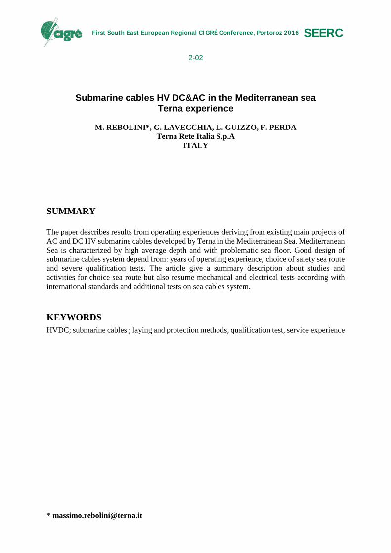
1. INTRODUCTION In the next decade the market for HV submarine cables is estimated at $ 25 billion and ¾ of the projects are in Europe where different links are under construction, while others are in the planning or feasibility studies (Figure 1). In Northern Europe primarily concern links offshore wind farms, while in the Mediterranean have predominant subject of interconnection links to promote the integration of renewable sources, security of supply and the integration of electricity markets. The challenges that arise are manifold not only technological but also environmental, economic, financial, social and political, the latter probably represent the greatest challenge to their achievement.
Figure 1 – HVDC Interconnections in Europe – at the present and in the future
The Mediterranean Sea (Figure 2) is a basin which connects to the Atlantic Ocean through the Strait of Gibraltar, with the Black Sea (considered a separate sea) through the Dardanelles and the Sea of Marmara and the Baltic red through the Suez channel (artificial). There are six large islands: Sicily, Sardinia, Corsica, Crete, Cyprus, and Mallorca and a total of about 3300 islands in the Mediterranean area.
Figure 2 – Mediterranean sea
The high depth is one of the main challenges in the construction and installation of electrical HV cables; a rather full examination of the technological challenges is summarized in [1] as a
2
state for deep applications cables can be found in [2] while the system aspects are given in [3]. The maximum depth of over 5000 m is touched in the Aegean basin near the Peloponnese, while the average depth is up to 1500 meters. For a comparison, the maximum depth in the North Sea is 700 meters (in the Skagerrak channel) while the average depth of about 100 meters.
2. PROJECTS HV AC AND DC -EXISTING 2.1. Introduction The Table I gives a summary of existing marine installation and under construction in the Mediterranean. The Terna projects completed or under construction account for over 60 % of projects in the Mediterranean, with more than 1400 km of submarine cables laid so far . In some cases HVDC Projects exceed 1000 m of laying depth.
Link Rated voltage Length Power
Sardinia-Corse-Italy (SACOI) 200 kV dc 105 km +15 km 300 MW
Sicily-Italy 1 (SORRIZ 1) 400 kV ac 7 km 800 MW
Greece-Italy (GRITA) 400 kV dc 160 km 500 MW
Sardinia-Corse (SARCO) 150 kV ac 15 km 150 MW
Morocco-Spain 400 kV ac 26 km 2 × 700MW
Maiorca-Spain ±250 kV dc 244 km 2 × 200 MW
Sardinia – Italy (SAPEI) ±500 kV dc 420 km 2 × 500 MW
Sicily-Italy 2&3 (SORRIZ 2&3) 400 kV ac 38 km 2 × 1000 MW
Montenegro - Italy (MONITA) ±500 kV dc 393 km 2 × 600 MW
Turkey –Europe(Dardanelles) 400 kV ac 5 km 2 × 1000 MW
Maiorca - Ibiza 132 kV ac 115 km 2 × 100 MW
Malta - Sicily 230 kV ac 100 km 2 × 225 MW
Capri-Torre Annunziata 150 kV ac 30 km 160 MW
Capri - Sorrento 150 kV ac 16 km 160 MW
Ischia - Cuma 150 kV ac 23 km 90 MW
Elba – Italian mainland 132 kV ac 35 km 160 MW
Lavrio – Syros (Greece) 150 kV ac 108 km 200 MW
Table I – Existing and under construction cable link in Mediterranean Sea – in bold the Terna’s links
2.2. Operating Experiences
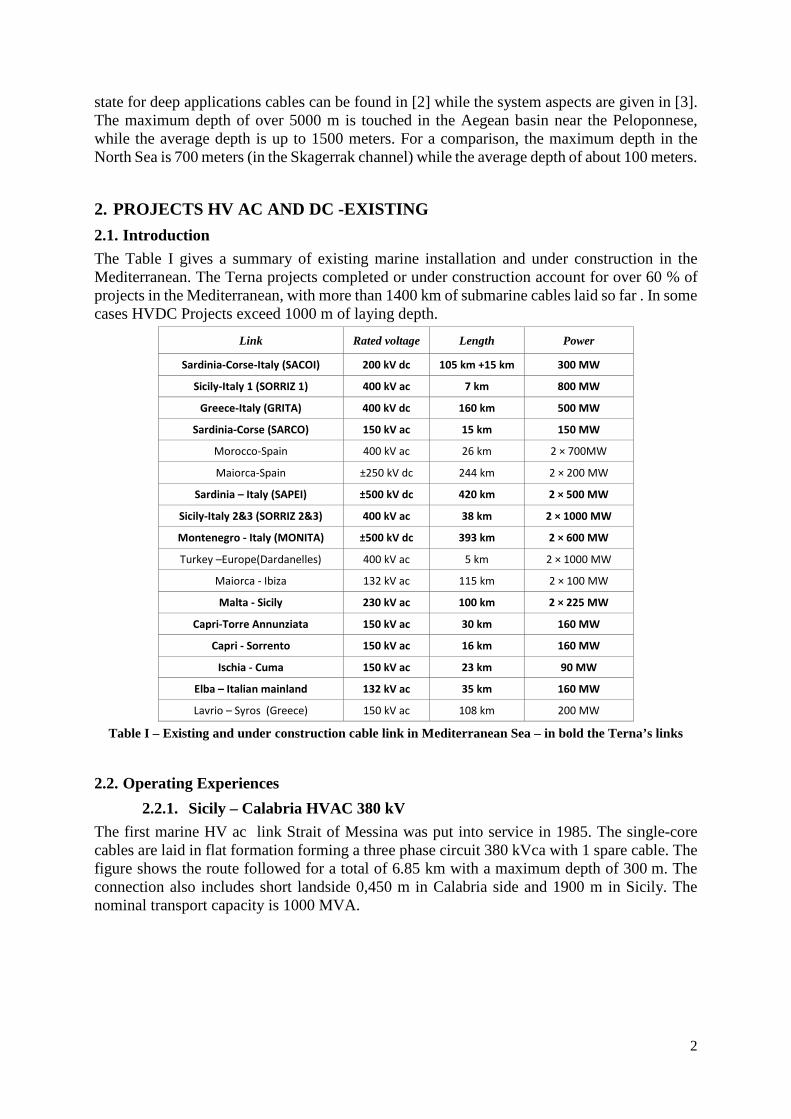
2.2.1. Sicily – Calabria HVAC 380 kV The first marine HV ac link Strait of Messina was put into service in 1985. The single-core cables are laid in flat formation forming a three phase circuit 380 kVca with 1 spare cable. The figure shows the route followed for a total of 6.85 km with a maximum depth of 300 m. The connection also includes short landside 0,450 m in Calabria side and 1900 m in Sicily. The nominal transport capacity is 1000 MVA.
3
Figure 3 – Cable route of Sicily-Calabria 380 kVac submarine cable link
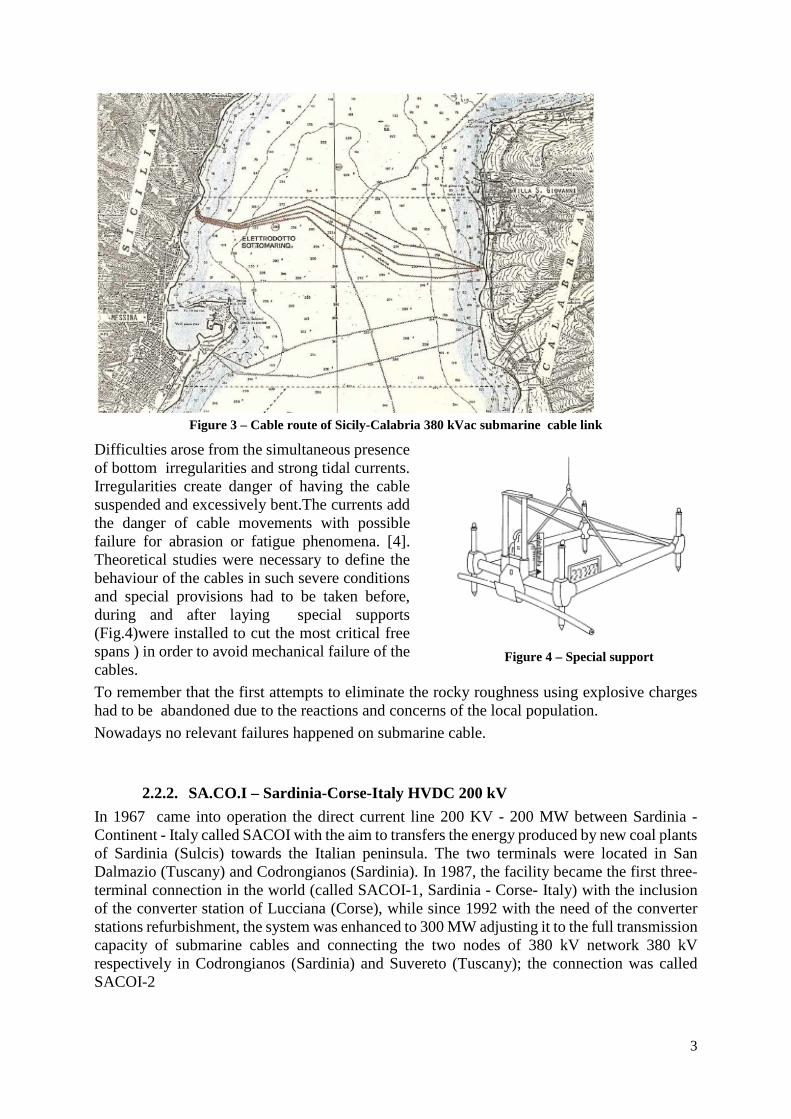
Difficulties arose from the simultaneous presence of bottom irregularities and strong tidal currents. Irregularities create danger of having the cable suspended and excessively bent.The currents add the danger of cable movements with possible failure for abrasion or fatigue phenomena. [4]. Theoretical studies were necessary to define the behaviour of the cables in such severe conditions and special provisions had to be taken before, during and after laying special supports (Fig.4)were installed to cut the most critical free spans ) in order to avoid mechanical failure of the cables. To remember that the first attempts to eliminate the rocky roughness using explosive charges had to be abandoned due to the reactions and concerns of the local population. Nowadays no relevant failures happened on submarine cable.
2.2.2. SA.CO.I – Sardinia-Corse-Italy HVDC 200 kV In 1967 came into operation the direct current line 200 KV - 200 MW between Sardinia - Continent - Italy called SACOI with the aim to transfers the energy produced by new coal plants of Sardinia (Sulcis) towards the Italian peninsula. The two terminals were located in San Dalmazio (Tuscany) and Codrongianos (Sardinia). In 1987, the facility became the first three-terminal connection in the world (called SACOI-1, Sardinia - Corse- Italy) with the inclusion of the converter station of Lucciana (Corse), while since 1992 with the need of the converter stations refurbishment, the system was enhanced to 300 MW adjusting it to the full transmission capacity of submarine cables and connecting the two nodes of 380 kV network 380 kV respectively in Codrongianos (Sardinia) and Suvereto (Tuscany); the connection was called SACOI-2
Figure 4 – Special support

4
The maximum depth of 450 meters, is reached at about 30 km from the Corsica shore. Four cables (two from Sardinia to Corse and two from Corse to Italian peninsula) were laid from the French cable ship "Marcel Bayard" in the summer of 1965. During laying (reflecting the importance of the planning of naval campaigns and checking weather forecasts) was necessary to halt operations and cut the final end of a cable. After that a field joint, prepared on the cable vessel, was necessary to complete the installation .The distance between the two cables was held in 300 meters in the Bonifacio channel and about 1500 meters to the Tyrrhenian Sea crossing.
Figure 5 – Cable route of SA.CO.I HVDC 200 kV submarine cable link
The cables conductor cross section is 420 mm2 copper with a current capacity of 750 A. In case of failure of one of the cables the remaining cable can carry 800 A for 15 days a year in emergency conditions. The conductor section is elliptical allowing to give a preferential direction to geometric deformation that the cable undergoes due to the effect of temperature changes according to the load. It is therefore sought to reduce the dangers of detachment of the insulating paper layers that could occur if, due to a decrease of the subsequent temperature and related dilation of strong external pressure causing wrinkles on the lead sheath; indeed at that time were feared effect of cables with round cross-section due to the imperfections of construction in respect of the perfect circularity.
5
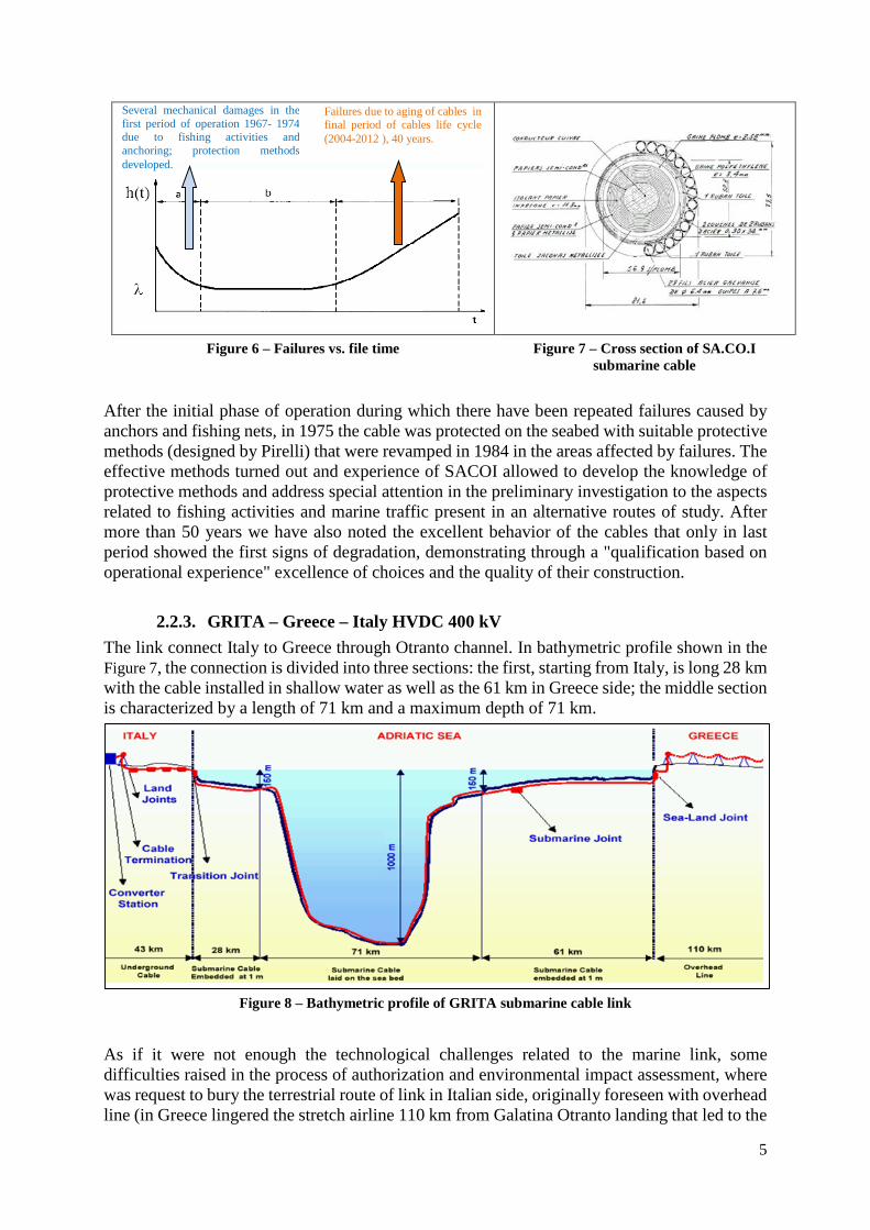
Figure 6 – Failures vs. file time Figure 7 – Cross section of SA.CO.I submarine cable
After the initial phase of operation during which there have been repeated failures caused by anchors and fishing nets, in 1975 the cable was protected on the seabed with suitable protective methods (designed by Pirelli) that were revamped in 1984 in the areas affected by failures. The effective methods turned out and experience of SACOI allowed to develop the knowledge of protective methods and address special attention in the preliminary investigation to the aspects related to fishing activities and marine traffic present in an alternative routes of study. After more than 50 years we have also noted the excellent behavior of the cables that only in last period showed the first signs of degradation, demonstrating through a "qualification based on operational experience" excellence of choices and the quality of their construction.
2.2.3. GRITA – Greece – Italy HVDC 400 kV The link connect Italy to Greece through Otranto channel. In bathymetric profile shown in the Figure 7, the connection is divided into three sections: the first, starting from Italy, is long 28 km with the cable installed in shallow water as well as the 61 km in Greece side; the middle section is characterized by a length of 71 km and a maximum depth of 71 km.
Figure 8 – Bathymetric profile of GRITA submarine cable link
As if it were not enough the technological challenges related to the marine link, some difficulties raised in the process of authorization and environmental impact assessment, where was request to bury the terrestrial route of link in Italian side, originally foreseen with overhead line (in Greece lingered the stretch airline 110 km from Galatina Otranto landing that led to the
Several mechanical damages in the first period of operation 1967- 1974 due to fishing activities and anchoring; protection methods developed.
Failures due to aging of cables in final period of cables life cycle (2004-2012 ), 40 years.
6
construction of an underground cable in oil-filled cable to 400 kV DC with a length of about 43 km. The land cable is one of the longest in the world ( terrestrial cable system HVDC Kontek (between Denmark and Germany) 600 MW - 400 kV that was put into service in 1995 is long 119 km is the same type of marine cable ( 55 km long ) to MIND in oil The cable solution was required by the authorities when the qualification test on submarine cable had already been performed and part of the type and acceptance tests on the cable and accessories (particularly the land cable is divided into 5 sections with 51 hydraulic joints) everything sizing was done on the basis of calculations considered conservative. Nevertheless, after more than ten years operation, it was necessary a refurbishment of the underground joints due to thermal issues; this required to defined a planned window for making all the activities in order to avoid service interruptions. This is a classic example of expensive environmental requirements that was feasible, but not consistent with technologies state of the art and that requires a careful and constant monitoring of the link for potential critical issue and keep reliable the connection. Note that similar problems were also recorded on the joints of the Kontek made by different manufacturer [6].
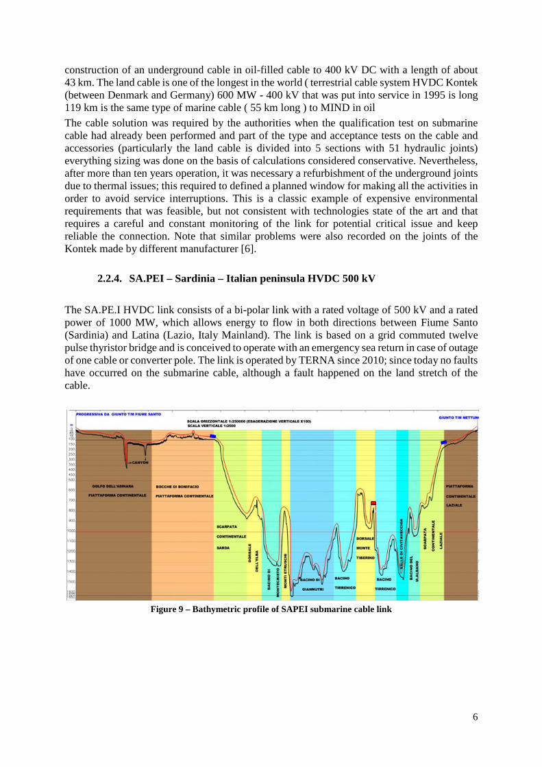
2.2.4. SA.PEI – Sardinia – Italian peninsula HVDC 500 kV The SA.PE.I HVDC link consists of a bi-polar link with a rated voltage of 500 kV and a rated power of 1000 MW, which allows energy to flow in both directions between Fiume Santo (Sardinia) and Latina (Lazio, Italy Mainland). The link is based on a grid commuted twelve pulse thyristor bridge and is conceived to operate with an emergency sea return in case of outage of one cable or converter pole. The link is operated by TERNA since 2010; since today no faults have occurred on the submarine cable, although a fault happened on the land stretch of the cable.
Figure 9 – Bathymetric profile of SAPEI submarine cable link

7
2.2.5. Operating Experience Synthesis Fault root analysis from technical literature [16], as shown in Figure 10, evidenced that the main factor of failure is due to the anthropogenic events, such as fishing (52%) and the anchors (18%). Consequently, in subsequent years, systems have been implemented as deterrent for links in service and/or to the electrode cables using concrete blocks laid on the bottom and connected to each other or tetrapods, or for protective purpose, such as jetting, trenching etc.. for connections of new construction. These measures have had the effect a drastic reduction of the failure rate. In particular, the convergence of several factors, such as, the operating data, the analysis of the seabed and identifying ways of fishing in areas subject to pose, it was possible to identify for each project bathymetry and depth of optimum underground. The results can be considered satisfactory, given a failure rate practically zero related to external factors of anthropic nature.
Figure 10 – Percentage of cause of failures on submarine cable
3. DESIGN PROCESS FOR SUBMARINE CABLE LINK The Mediterranean also has other factors to consider in the design and laying of submarine cables in particular:
− Maritime activities and great fishing; − study of the seabed: bathymetry, geology, morphology tectonics (with the presence of
canyons and slopes of relief), seismicity, volcanism; − meteorological and surface wave and at various depths: strong currents in some areas; − although an extension of the coasts of about 46000 km difficulty of finding landing
places suitable for cables and their connection to the electricity grid; − presence of marine protected areas and important for biodiversity; − heating water temperature; − polluted areas; − area for oil exploration and sand areas with pick concessions from the seabed; − wrecks and archaeological finds; − interferences with other infrastructures like submarine links for gas pipelines and
telecommunications cables; These data make sense of the difficulties related to the installation of submarine connections in the Mediterranean and the need to study each individual system for choosing the best use technology. In addition, under extreme mechanical conditions, the cable project and its installation are highly interdependent and should be studied in order to optimize performance and reduce risk.
8
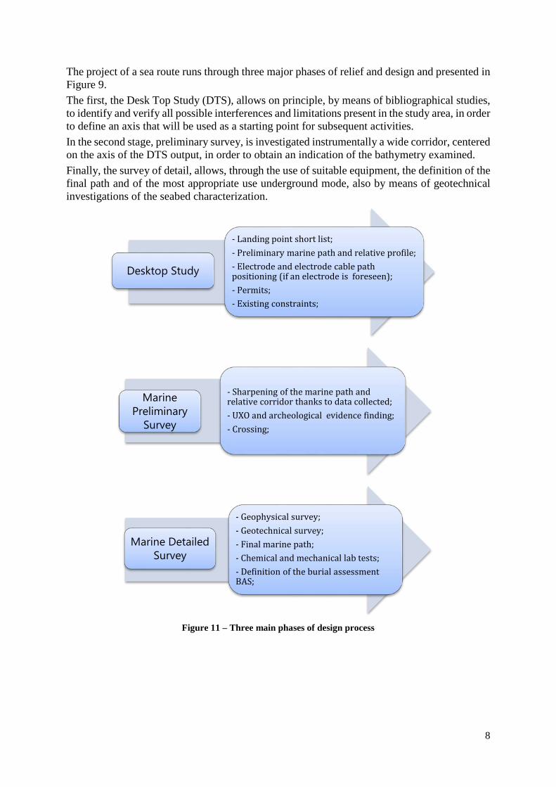
The project of a sea route runs through three major phases of relief and design and presented in Figure 9. The first, the Desk Top Study (DTS), allows on principle, by means of bibliographical studies, to identify and verify all possible interferences and limitations present in the study area, in order to define an axis that will be used as a starting point for subsequent activities. In the second stage, preliminary survey, is investigated instrumentally a wide corridor, centered on the axis of the DTS output, in order to obtain an indication of the bathymetry examined. Finally, the survey of detail, allows, through the use of suitable equipment, the definition of the final path and of the most appropriate use underground mode, also by means of geotechnical investigations of the seabed characterization.
Figure 11 – Three main phases of design process
Desktop Study
- Landing point short list;- Preliminary marine path and relative profile;- Electrode and electrode cable path positioning (if an electrode is foreseen);- Permits;- Existing constraints;
Marine Preliminary
Survey
- Sharpening of the marine path and relative corridor thanks to data collected;- UXO and archeological evidence finding;- Crossing;
Marine Detailed Survey
- Geophysical survey;- Geotechnical survey;- Final marine path;- Chemical and mechanical lab tests;- Definition of the burial assessment BAS;

9
4. TESTING AND QUALIFICATION PROCESS OF A SUBMARINE CABLE SYSTEM
A submarine cable system before being installed and put into operation must be subjected to a qualification process with the aim to verify the correspondence of the cable to the specific design defined in technical specification in relation to the type of installation and application envisaged. The submarine cable links, given the considerable lengths, require substantial up-front investment and repair costs in case of failure can be very high if it is necessary to intervene to restore the connection, as well as result in a loss of profitability during the our of service. Therefore is necessary that the cable system has a high degree of quality, and then is subjected to a qualification and testing process with the purpose of checking the reliability starting from the stages of development and design to manufacturing and to the subsequent laying in the sea. The qualification tests for submarine cables differ depending on the cable technology and application; the main technologies installed in Terna electrical network are shown: Cables with extruded insulation for AC and DC applications: − Pre-qualification test (for cables with nominal electrical stresses greater than 8 kV/mm and
4 kV/mm respectively on the conductor and insulation); − Type tests; Oil-filled cable for AC applications: − Type tests; MIND cables (mass impregnated) for DC applications: − Type tests. The qualification tests are performed according to national standards CEI, international CENELEC and IEC, in addition to Cigré documents (Table II). Furthermore, considering that marine cables have characteristics with high degree of specialization, unlike terrestrial cables, Terna conducts special tests in relation to specific issues not fully covered by the aforementioned standards. Similarly, as part of the qualification tests is required to perform the sea trials test which are intended to simulate the conditions of the most demanding installations and verify the interaction of cable system with the laying equipment and protection techniques.
Standard Title Ref.
Cigré TB 623 (2015)
Recommendations for mechanical testing of submarine cables - WG B1.43, June 2015 [A]
IEC 60840 Ed.4.0: 2011-11
Power cables with extruded insulation and their accessories for rated voltages above 30 kV (Um = 36 kV) up to 150 kV (Um = 170 kV) – Test method and requirements
[B]
IEC 62067 Edition 2.0 2011-
11
Power cables with extruded insulation and their accessories for rated voltages above 150 kV (Um = 170 kV) up to 500 kV (Um = 550 kV) – Test methods and requirements
[C]
Cigré TB 496 (2012)
Recommendations for testing DC extruded cable systems for power transmission at a rated voltage up to 500 kV - WG B1.32, April 2012 [D]
Cigré TB 490 (2012)
Recommendations for Testing of Long AC Submarine Cables with Extruded Insulation for System Voltage above 30 (36) to 500 (550) kV – WG B.27, February 2012
[E]
Cigré Electra No. 189
Reccomendation for tests of power transmission DC cables for rated voltage up to 800 kV (Electra 72, 1980 – Revision) – WG 21.02, April 2000 [F]
Table II – References standards for tests on submarine cables
In addition to the qualification tests, submarine cables and their accessories are subjected to tests during the manufacturing process in the factory and consist of:
10
− Routine tests: tests made by manufacturer on each manufactured component to check that the component meets the specified requirements. For the cable is recommended to perform the tests before the armouring process because solving a problem in case of failure on a cable just armoured, would be costly both in terms of costs and time [15];
− Sample tests: tests made by the manufacturer on samples of complete cable, or components taken from a complete cable or accessory, at a specified frequency, so as to verify that the finished product meets the specified requirements [15].
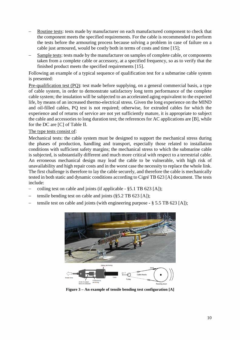
Following an example of a typical sequence of qualification test for a submarine cable system is presented: Pre-qualification test (PQ): test made before supplying, on a general commercial basis, a type of cable system, in order to demonstrate satisfactory long term performance of the complete cable system; the insulation will be subjected to an accelerated aging equivalent to the expected life, by means of an increased thermo-electrical stress. Given the long experience on the MIND and oil-filled cables, PQ test is not required; otherwise, for extruded cables for which the experience and of returns of service are not yet sufficiently mature, it is appropriate to subject the cable and accessories to long duration test; the references for AC applications are [B], while for the DC are [C] of Table II. The type tests consist of: Mechanical tests: the cable system must be designed to support the mechanical stress during the phases of production, handling and transport, especially those related to installation conditions with sufficient safety margins; the mechanical stress to which the submarine cable is subjected, is substantially different and much more critical with respect to a terrestrial cable. An erroneous mechanical design may lead the cable to be vulnerable, with high risk of unavailability and high repair costs and in the worst case the necessity to replace the whole link. The first challenge is therefore to lay the cable securely, and therefore the cable is mechanically tested in both static and dynamic conditions according to Cigré TB 623 [A] document. The tests include: − coiling test on cable and joints (if applicable - §5.1 TB 623 [A]); − tensile bending test on cable and joints (§5.2 TB 623 [A]); − tensile test on cable and joints (with engineering purpose - § 5.5 TB 623 [A]);
Figure 3 – An example of tensile bending test configuration [A]
11
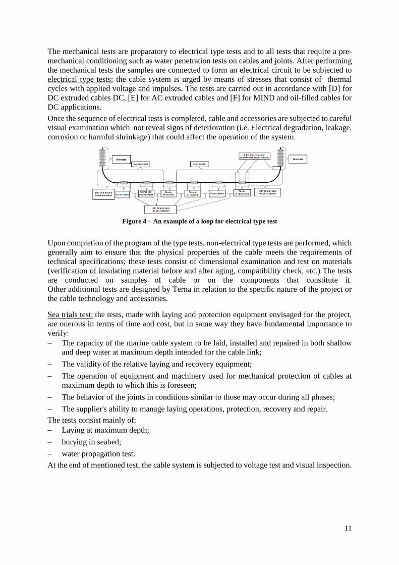
The mechanical tests are preparatory to electrical type tests and to all tests that require a pre-mechanical conditioning such as water penetration tests on cables and joints. After performing the mechanical tests the samples are connected to form an electrical circuit to be subjected to electrical type tests; the cable system is urged by means of stresses that consist of thermal cycles with applied voltage and impulses. The tests are carried out in accordance with [D] for DC extruded cables DC, [E] for AC extruded cables and [F] for MIND and oil-filled cables for DC applications. Once the sequence of electrical tests is completed, cable and accessories are subjected to careful visual examination which not reveal signs of deterioration (i.e. Electrical degradation, leakage, corrosion or harmful shrinkage) that could affect the operation of the system.
Figure 4 – An example of a loop for electrical type test
Upon completion of the program of the type tests, non-electrical type tests are performed, which generally aim to ensure that the physical properties of the cable meets the requirements of technical specifications; these tests consist of dimensional examination and test on materials (verification of insulating material before and after aging, compatibility check, etc.) The tests are conducted on samples of cable or on the components that constitute it. Other additional tests are designed by Terna in relation to the specific nature of the project or the cable technology and accessories.
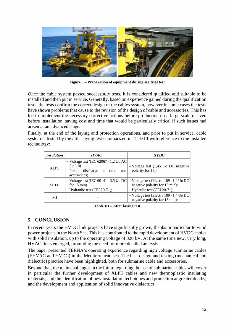
Sea trials test: the tests, made with laying and protection equipment envisaged for the project, are onerous in terms of time and cost, but in same way they have fundamental importance to verify: − The capacity of the marine cable system to be laid, installed and repaired in both shallow
and deep water at maximum depth intended for the cable link; − The validity of the relative laying and recovery equipment; − The operation of equipment and machinery used for mechanical protection of cables at
maximum depth to which this is foreseen; − The behavior of the joints in conditions similar to those may occur during all phases; − The supplier's ability to manage laying operations, protection, recovery and repair. The tests consist mainly of: − Laying at maximum depth; − burying in seabed; − water propagation test. At the end of mentioned test, the cable system is subjected to voltage test and visual inspection.
12
Figure 5 – Preparation of equipment during sea trial test
Once the cable system passed successfully tests, it is considered qualified and suitable to be installed and then put in service. Generally, based on experience gained during the qualification tests, the tests confirm the correct design of the cables system, however in some cases the tests have shown problems that cause to the revision of the design of cable and accessories. This has led to implement the necessary corrective actions before production on a large scale or even before installation, saving cost and time that would be particularly critical if such issues had arisen at an advanced stage. Finally, at the end of the laying and protection operations, and prior to put in service, cable system is tested by the after laying test summarized in Table III with reference to the installed technology:
Insulation HVAC HVDC
XLPE
− Voltage test (IEC 62067 - 1,2 Uo AC for 1 h)
− Partial discharge on cable and accessories;
− Voltage test (1,45 Uo DC negative polarity for 1 h);
SCFF − Voltage test (IEC 60141 - 3,5 Uo DC
for 15 min) − Hydraulic test (CEI 20-71);
− Voltage test (Electra 189 - 1,4 Uo DC negative polarity for 15 min);
− Hydaulic test (CEI 20-71);
MI -- − Voltage test (Electra 189 - 1,4 Uo DC negative polarity for 15 min);
Table III – After laying test
5. CONCLUSION In recent years the HVDC link projects have significantly grown, thanks in particular to wind power projects in the North Sea. This has contributed to the rapid development of HVDC cables with solid insulation, up to the operating voltage of 320 kV. At the same time new, very long, HVAC links emerged, prompting the need for more detailed analysis. The paper presented TERNA’s operating experience regarding high voltage submarine cables (EHVAC and HVDC) in the Mediterranean sea. The best design and testing (mechanical and dielectric) practice have been highlighted, both for submarine cable and accessories. Beyond that, the main challenges in the future regarding the use of submarine cables will cover in particular the further development of XLPE cables and new thermoplastic insulating materials, and the identification of new installation techniques and protection at greater depths, and the development and application of solid innovative dielectrics.
13
6. BIBLIOGRAPHY [1] P.Adam, E.Colombo, S.Sim, A.Burns “Specific submarine cable system challenges for the
development of a Mediterranean Interconnection Grid” Cigre General session 2014 Paris (France) paper B1-302;
[2] M.Bacchini, M.Marelli, A.Orini, (Prysmian PowerLink) “Cables for deep water applications ”, A.6.3 Jicable 2011 Versailles (France);
[3] L.Colla, M.Marelli, S.Lauria, M.Schembari, F.Palone, M.Rebolini (Prysmian Powerlink, Terna, Università Sapienza Roma) “Collegamenti in cavo sottomarino nel mar Mediterraneo:aspetti tecnologici e di sistema”AEIT Conferenza Annuale 2013 Mondello, Palermo ottobre 2013;
[4] L.Rebuffat, G.M.Lanfranconi, F.Magnani, U.Arnaud, G.Monti "Installation of submarine power cables in difficult environmental conditions: the experience with 400 kV Messina cables” CIGRE General Session 1984 Paris (France) paper 21-10;
[5] A.Orini et alii ( Pirelli Cavi,ENEL) “Qualification test program for the 400 kV HVDC deep water interconnection between Italy and Greece CIGRE General Session 1996, Paris (France) paper 21-304;
[6] T. Kvarts, U.Gudmundsdottir ( ENERGINET) “Experience in service of HVDC cables, prospects of extruded polymer insulations” Jicable-HVDC 2013;
[7] A.Orini et alii (Prysmian, Terna, CESI) “Qualification test program for the 1000 MW-500 kV HVDC vey deep water submarine cable interconnection between Sardinia island and italian peninsula (SA.PE.I.)“ CIGRE General Session 2008, Paris (France) paper B1-104;
[8] L.Colla et alii (Terna, Università Sapienza Roma, Enemalta, CESI) “HVAC submarine cable links between Italy and Malta.Feasibility of the project and system electrical design“ CIGRE General Session 2010, Paris (France) paper B1-104;
[9] Cigré TB 398 WG B1.21 December 2009: “Third-Party Damage to Underground and Submarine Cables”;
[10] Cigré TB 379 WG B1.10 April 2009: “Update of service experience of HV underground and submarine cable systems”;
[11] Cigré TB 219 (2003), “Recommendations for testing DC extruded cable systems for power transmission at a rated voltage up to 500 kV”, Working group B1.32, April 2012.
[12] Cigré TB 623 WG B1.43 June 2015: “Recommendations for mechanical testing of submarine cables”;
[13] IEEE Std 1120-2004:”IEEE Guide for the Planning, Design, Installation, and Repair of Submarine Power Cable Systems”;
[14] IEC 60840 Ed.4.0: 2011-11 “Power cables with extruded insulation and their accessories for rated voltages above 30 kV (Um = 36 kV) up to 150 kV (Um = 170 kV) – Test method and requirements”;
[15] IEC 62067 Ed.2.0: 2011:11 “Power cables with extruded insulation and their accessories for rated voltage above 150 kV (Um = 170 kV) up to 500 kV (Um = 550 kV) – Test methods and requirements”;
[16] T. Worzyk “Submarine Power Cables Design, Installation, Repair, Environmental Aspects”, Springer editions, ISBN 978-3-642-01270-9