Embed Size (px)
Citation preview

CHAP. I-BUREAU MARINE INSPECTION, NAVIGATION
having an inside diameter of over 6 inches to 15 inches, inclusive,one-eighth of an inch.
D=diameter inside in inches. When the pressure is to be deter-mined for a part of a flat surface which is a square, or rec-tangle in the flat-surface formula, the value of D used shallbe the diagonal of the square or rectangle, and when theends are bolted to the shell the value of D used shall equalthe diameter of the bolt circle.
All flanges shall be substantial, and there shall be a good fillet allaround the root, and when the ends and shell are cast solid there shallbe a good and substantial fillet inside all around.
The bolts or studs for the ends or doors shall not have a greaterstress than 6,000 pounds per square inch, and the size of bolts orstuds shall be not less than three-fourths of an inch in diameter.
EVAPORATOR S
Evaporators shall be provided with an efficient safety valve ofapproved type, set to blow at the maximum pressure to which theevaporator will be subjected in service, and it shall be the duty of theengineer in charge of the vessel to see that such valve blows off atleast once in 30 days.*t [As amended by Monthly Bulletin 191,Sept. 1, 1931]
Subchapter G-Ocean and Coastwise: General Rules andRegulations
PART 59-BOATS, RAFTS, BULKHEADS, AND LIFE-SAVINGAPPLIANCES (OCEAN)
Sec.59.1 Ocean steamers.59.2 Davits required.59.3 Strength and operation of davits.59.3a Mechanical means for lowering.59.4 Lifeboats required: Vessels of
classes (a) and (b).59.4a Buoyant apparatus required.59.5 Motor-propelled lifeboats.59.6 Lifeboats required on vessels of
class (c).59.7 Carrying of lifeboats on vessels
of classes (a) and (b).59.8 Lifeboats required on inspected
motor vessels.59.9 Lifeboat and other equipment re-
quired on sail vessels.59.10 Lifeboats and their equipment re-
quired on inspected seagoingbarges of 100 gross tons or over.
59.10a General requirements as to equip-ment for lifeboats, life rafts andbuoyant apparatus.
59.11 Lifeboat equipment.
See.59.11a Motor lifeboat equipment.59.12 Standard types of boats.59.13 Drawings, specifications, name
plate.59.14 Inspection of lifeboats when
built.59.15 Construction of metallic life-
boats of class IA.59.16 Construction of wooden life-
boats.59.17 Open boats with internal and
external buoyancy; class lB.59.18 Lundin and Lane lifeboats.59.19 Boats equivalent to boats of
class lB.59.20 Pontoon boats in which persons
can not be accommodated belowdeck, having a well deck andfixed water-tight bulwarks;class 1C.
59.21 Boats of the second class.59.22 Open boats having the upper
part of the sides collapsible;class 2A.
*tFor statutory and source citations, see note to § 58.1. Page651[773]
§ 58.28

TITLE 46-SHIPPING
Sec.59.23 Pontoon boats having a well
deck and collapsible bulwarks;class 2B.
59.24 Pontoon boats in which personscan not be accommodated belowdeck, having a flush deck andcollapsible bulwarks; class 2C.
59.25 Arrangements for clearing pon-toon lifeboats of water.
59.26 Type of boat equivalent to boatof class 2.
59.27 Brude lifeboat.59.28 Capacity and allowance of En-
gelhardt collapsible lifeboats.59.29 Newcomb inclosed lifeboat.59.30 Air tanks of lifeboats.59.31 Cubic capacity of open boats of
the first class.59.32 Deck area of pontoon boats and
open boats of the second class.59.33 Capacity limits.59.34 Equivalents for and weight of
the persons.59.35 Numbering and marking of life-
boats.59.36 Lifeboats and liferafts kept
clear for launching.59.37 Boat-davit falls and receptacles
therefor.59.38 Care of lifeboats.59.39 Tests of boats at annual inspec-
tion.59.40 Size of boats.
Sec.59.41 Handling of the boats and rafts.59.42 Liferafts: Drawings, specifica-
tions, name plate, and howmarked.
59.43 Inspection of liferafts whenbuilt.
59.44 Construction of rafts of the ca-tamaran type.
59.45 Tests of air tanks of liferafts.59.46 Care of liferafts.59.47 Approved liferafts.59.48 Clark liferafts.59.50 Capacity and allowance of life-
rafts.59.52 Equipment for liferafts.59.53 Certificated lifeboat men; man-
ning of the boats.59.54 Manning of the boats.59.54a Buoyant apparatus.59.54b Equipment for buoyant appara-
tus.59.55 Life preservers.59.56 Ring life buoys.59.57 Self-igniting water lights.59.60 Line carrying guns and equip-
ment.59.61 Line-throwing appliances.59.62 Extra steering apparatus.59.63 Embarkation aids.59.64 Bulkheads.59.65 Means of escape from steamers.59.66 Storm oil.59.67 Vessel's name on equipment.
Section 59.1 Ocean steamers. Under this designation shall beincluded all steam vessels navigating the waters of any ocean or theGulf of Mexico more than 20 nautical miles offshore. For the pur-pose of apportioning lifeboat, life-raft, and davit equipment uponocean steam vessels subject to the jurisdiction of the Bureau ofMarine Inspection and Navigation, they shall be divided into thefollowing classes:
(a) Passenger steam vessels.(b) Passenger steam vessels the keels of which are laid after
July 1, 1915.(c) Cargo steam vessels and all other steam vessels navigating the
waters of any ocean, unless hereinafter provided for.*t*§§ 59.1 to 59.67, inclusive, issued under the authority contained in R.S.
4405, 4488; as amended, 46 U.S.C. 375, 481. Additional statutory provisionsnoted in parentheses at the end of particular sections are applicable to suchsections.
tIn §§ 59.1 to 59.61, inclusive, (except §§ 59.3a, 59.4a, 59.10a, 59.11a, 59.54a,59.54b, added by Supplement I), the numbers to the right of the decimal pointcorrespond with the respective section numbers in Rule III, General rulesand regulations (Ocean), Ocean and Coastwise, Board of Supervising Inspectors(Bureau of Marine Inspection and Navigation), Mar. 2, 1931. Amendmentsare noted in brackets following section affected.
59.2 Davits required. Vessels of classes (a) and (b) shall beequipped with davits in accordance with the following table:
Page 652(774]
§ 59.1

CHAP. I-BUREAU MARINE INSPECTION, NAVIGATION § 59.3
Minimum Minimumnumber of number of Minimum
Registered length of ship in feet ses of open boats capacity of
davits of the first lifeboatsclass
100 and less than 120 ...........120 and less than 140 ............140 and less than 160 .....160 and less than 175 ---------------175 and less than 190 ....190 and less than 205 ---------------205 and less than 220 ....220 and less than 230 ....230 and less than 245-------------245 and less than 255 ..............255 and less than 270 ---------------270 and less than 285-------------285 and less than 300 --------------300 and less than 315.............315 and less than 330 ---------------330 and less than 350-_350 and less than 370370 and less than 390 .....390 and less than 410-.410 and less than 435 .....435 and less than 460 .....460 and less than 490 .....490 and less than 520 .....520 and less than 550.............550 and less than 580 .....580 and less than 610 .....610 and less than 640640 and less than 670-------------670 and less than 700 .....700 and less than 730 -------------730 and less than 760760 and less than 790 -------------790 and less than 820 .....820 and less than 855855 and less than 890-------------890 and less than 925 -------------925 and less than 960 .....960 and less than 995995 and less than 1,030-_
Cubic feet980
1,2201, 5501, 8802, 3902, 7403, 3303, 9004, 5605, 1005, 6406, 1906, 9307, 5508, 2909, 0009, 630
10, 65011, 70013, 06014, 43015, 92017, 31018, 72020, 35021, 90023, 70025, 35027, 05028, 56030, 18032, 10034, 35036, 45038, 75041, 00043, 88046, 35048, 750
The minimum number of sets of davits is fixed in relation to thelength of the vessel; provided that a number of sets of davits greaterthan the number of boats necessary for the accommodation of all thepersons on board may not be required.*t
59.3 Strength and operation of davits. (a) The davits shall beof such strength that the boats can be lowered with their full com-plement of persons and equipment, the vessel being assumed to havea list of 150.
(b) The davits shall be fitted with a gear of sufficient power toinsure that the boat can be turned out against the maximum list
*t~or statutory and source citations, see note to § 59.1. Page 653[775]

under which the lowering of the boats is possible on the vessel inquestion.
(c) The Secretary of Commerce is authorized by the Seamen'sAct (sec. 14, 38 Stat. 1178, 1181; 46 U.S.C. 481) in specific cases toexempt existing vessels from the requirements of this section that thedavits shall be of such strength and shall be fitted with a gear ofsufficient power to insure that the boats can be lowered with theirfull complement of persons and equipment, the vessel being assumedto have a list of 150, where their strict application would not bepracticable or reasonable.
(d) Each set of davits shall have a boat of the first class attachedto it, provided that the number of open boats of the first class at-tached to davits shall not be less than the minimum number fixed bythe preceding table.
(e) If it is neither practicable nor reasonable to place on a vesselthe minimum number of sets of davits required, a smaller number ofsets of davits may be fitted, provided always that this number shallnever be less than the minimum number of open boats of the firstclass required by the table. If a large proportion of the persons onboard is accommodated in boats whose length is greater than 50feet, a further reduction in the number of sets of davits may beallowed exceptionally, if the arrangements are in all respects satis-factory. Provided, however, That in all cases in which a reductionin the minimum number of sets of davits or other equivalent ap-pliances required by the rules is allowed, the owner of the vessel inquestion shall be required to prove, by a test made in the presenceof an officer designated by the Director of the Bureau of MarineInspection and Navigation, that all the boats can be efficientlylaunched in a minimum time. The conditions of this test shall be asfollows:
(1) The vessel is to be upright and in smooth water.(2) The time is the time required from the beginning of the
removal of the boat covers, or any other operation necessary toprepare the boats for lowering, until the last boat or pontoon raft isafloat.
(3) The number of men employed in the whole operation shallnot exceed the total number of boat hands that will be carried onthe vessel under normal service conditions.
(4) Each boat when being lowered shall have on board at leasttwo men and its full equipment as required by this part and Part 60.
(5) The time allowed for this test shall not exceed 10 minutes.(f) Vessels of class (c) shall be equipped with davits or other
practicable means for properly launching the lifeboats. Mechanicaldavits, when installed on vessels of class (c), shall be subject to allthe tests required by this section.
(g) On and after May 1, 1920, the complete installation of allmechanical boat davits shall be tested and demonstrated for strengthand efficiency at the place of manufacture in the presence of an in-spector of the Bureau of Marine Inspection and Navigation. Theframe, gear, worms, arms, and all machinery in connection with theoperation of the device shall be set up in the shop in the same man-
Page 654[776]
§ 59.3 TITLE 4 6-SHIPPING

CHAP. I-BUREAU MARINE INSPECTION, NAVIGATION § 59.3
ner as when installed for use on board the ship and shall be testedin the following manner: A weight equal to the weight of the boatwith its equipment and complement of persons that the davit is in-tended to serve, the weight of the persons being considered as 140pounds each, shall be suspended from the eye or end of each davitarm, and while the weight is in suspension, the davit arm shall beoperated from the inboard position to the full outboard position withthe same operating crank or device that is used in actual practiceon board the ship. Under this test the davit arm shall show nopermanent set or deflection, and the frame, gear, and operatingmechanism shall show no distress or distortion. While this test isbeing conducted, the frame, gear, and operating mechanism, if ofcast material, shall be subjected to a test by being well hammered,to satisfy the inspector that the castings are sound and without flaw.
(h) When the assembled installation meets the foregoing require-ments and the inspector is satisfied that the device is sufficient instrength and operation he shall stamp the davit arm and the frameto which it is attached, which shall bear identical numbers of themanufacturer, with the letters "U. S. I.," the initials of his name,and a serial number.
(i) When steel castings are employed for frames or davit arms,the castings shall be thoroughly annealed, and the tensile strengthof the castings shall be not less than 58,000 pounds nor more than78,000 pounds per square inch, with an elongation of not less than 20percent in a length of 2 inches measured on the test piece usedin determining the tensile stress. The test piece shall have a sec-tion 21/2 inches in the center turned down to one-half inch diameter.An inspector of this service shall witness this test. Sample piecesshall be a part of the annealed casting and shall represent the castingafter it has been thoroughly annealed, and if the casting has after-wards been heated for any purpose it shall be again annealed. Themanufacturer shall furnish the inspector, when required, an affidavitsetting forth the fact that the required tests respecting annealinghave been fully complied with. The davit arm, if of cast material,shall be raised to an angle of 450, the lower end resting upon theground, and dropped on a hard unyielding base, and then slungup and subjected to a test by being well hammered with a sledgehammer not less than 7 pounds in weight, to satisfy the inspectorthat the casting is sound and without flaw. An inspector of theBureau of Marine Inspection and Navigation shall be present at thefoundry where such castings are made, and when the foregoingspecifications and tests referred to in this paragraph have been com-plied with to his satisfaction, he shall stamp the davit arm and thedavit frame with the letters "U. S. I.," the initials of his name, andthe letters "F. T." indicating that the foundry tests have beencomplied with.
(j) No davit arm or frame comprising mechanical davits shall beplaced on board any vessel until all these requirements have beenfully complied with. Whenever mechanical davits or parts ofdavits; such as davit arms or frames, are installed on vessels to takethe place of davits, davit arms or frames which have become damaged
Page 655[777]

TITLE 4 6-SHIPPING
or broken, such davits or parts shall have in addition to the manu-facturer's name plate a substantial bronze plate showing that therespective parts are for replacement, this additional plate to indicatethe name of the manufacturer, serial number of the davit, and thedate. Such replacements and repairs to davits shall be tested inaccordance with the provisions of this section, and when the inspec-tor is satisfied that the device is sufficient in strength and operation,he shall stamp the letters "U. S. I.," and the initials of his name onthe plate.
(k) After October 31, 1926, all cast-steel mechanical davits carriedin stock, which have not been tested as above described, shall besubjected to the drop, hammer, suspension, and turning-out tests,and stamped by an inspector, all as above described, before suchdavits are accepted as lawful equipment.*t [As amended by Supp.I, p. 13, May 28, 1938]
59.3a Mechanical means for lowering. On passenger vessels,where the height of the boat deck exceeds 20 feet from the lightestseagoing draft, wire falls and mechanical means for lowering shallbe provided for each lifeboat. The wire ropes shall be securelyattached to the drum of the boat winch. The winch drums are tobe arranged to keep the two falls separate, and the lead of the wiresshall be such that they will wind evenly on the drums and in suchmanner that the falls may be paid out at the same rate. Brake gearsare to be so arranged that normally they are in the "on" positionand return to the "on" position when the handle is not being oper-ated. When more than one lifeboat is served by the same wire falls,the winches shall be fitted with quick return hand gear so that thefalls may be rapidly recovered. (Effective on all new passengervessels immediately and on existing passenger vessels July 1, 1938.) *t[As added by Supp. I, p. 14, May 28, 1938]
59.4 Lifeboats required: Vessels of classes (a) and (b). Ves-sels of classes (a) and (b) shall be equipped with lifeboats in accord-ance with the preceding table, provided that such vessels shall notbe required to carry more lifeboat capacity than is necessary toaccommodate all persons on board. If the lifeboats attached todavits do not provide accommodations for the vessel's actual comple-ment of passengers and crew additional lifeboats of one of thestandard types shall be installed to accommodate all persons on board,or to bring the complement of lifeboat capacity up to the minimumprovided by the table2 or to 75 percent of the complement of peopleon board, whichever is the greater. The remainder of the requiredequipment shall be provided by lifeboats of one of the standardtypes or approved life rafts. One of the lifeboats on each side ofa vessel shall be of suitable size and design for doing emergencywork at sea. Each of these boats shall be provided with at leastfour life lines fitted to a span between the davit heads of sufficientlength to reach the water at the vessel's lightest sea-going draft.A releasing gear of the type which may be unhooked under tensionis recommended in these boats. A sea painter should be passed alongforward on the vessel when at sea and in the lifeboat a lofig eye,
Page 656 *tpor statutory and source citations, see note to § 59.1.[7781
§ 59.3a

CHAP. I-BUREAU MARINE INSPECTION, NAVIGATION § 59
strop, and toggle should be fitted.*t [As amended by Supp. I, p. 11,May 28, 1938]
59.4a Buoyant apparatus required. On and after January 1,1936, approved buoyant apparatus sufficient to accommodate 25 per-cent of all persons on board shall be required in addition to thelifesaving equipment specified above. Buoyant apparatus shall bestowed as follows:
(a) They shall not impede in any way prompt handling of life-boats, or the marshaling of persons on board at launching stations.
b) They shall be stowed in such manner as to be readily launched.c) They shall not be secured to the deck except by lashings which
can be easily slipped -but they may be stowed in tiers one above theother, in which case the separate units shall be kept apart sufficientlyto prevent sticking together, and supported on suitable distancepieces.
(d) Means shall be provided to prevent shifting.(e) Discretionary with the Bureau. the amount above required
may be reduced when it is of the opinion that the construction, typeand route of individual vessels warrant a reduction.
(f) Where buoyant apparatus has been supplied and is now inuse on vessels built in conformity with the rules of the Conventionfor the Safety of Life at Sea, 1929, in ood condition, and the appa-ratus conforms to the specifications of the convention, it may be keptin use on the ship for which it was originally supplied.*t [Asadded by Supp. I, p. 14, May 28, 1938]
CRoss REFERENCE: For acceptance of safety certificates issued under Inter-national Convention, 1929, see Part 10.
59.5 Motor-propelled lifeboats. All passenger vessels certifi-cated for ocean service shall be provided, as part of their regularequipment, with motor-propelled lifeboats as follows:
(a) Ships of more than 2,500 gross tons, plying routes on whichthey are at any point more than 200 miles offshore, shall be providedwith one motor-propelled lifeboat.
(b) Ships on which the number of lifeboats carried is more thanthirteen shall be provided with one motor-propelled lifeboat.
(c) Where the number of lifeboats carried is more than 19, 2 shallbe motor-propelled lifeboats.
(d) Any lifeboat certified to carry 100 or more persons shall,if not one of the motor lifeboats required above, be motor-propelledor fitted with a hand-operated propellor.
(e) Motor-propelled lifeboats shall comply with the requirementsfor a lifeboat of class 1; and the volume of the internal buoyancyand, where fitted, the external buoyancy shall be increased in suf-ficient proportion to compensate for the difference between the weightof the motor, the searchlight, and the radiotelegraph installation andtheir accessories, and the weight of the additional persons which theboat could accommodate if the motor, searchlight, and the radio-telegraph installation and their accessories were removed.*t (R.S.4417, as amended; 46 U.S.C. 391) [As amended by Supp. I, p. 11,May 28, 1938]
*tFor statutory and source citations, see note to § 59.1. Page 657[7791

TITLE 4 6-SHIPPING
59.6 Lifeboats required on vessels of class (c). (a) Cargo ves-sels shall carry a sufficient number of lifeboats on each side to ac-commodate all persons on board.
(b) Fishing and wrecking vessels shall carry sufficient lifeboatsto accommodate all persons on board, and the following types ofboats may be used in lieu of the standard lifeboats:
(1) Vessels engaged exclusively in the business of purse seiningmay use their wooden seine boats.
(2) Vessels engaged exclusively in the business of wrecking mayuse their wooden surf boats.
(3) Vessels engaged exclusively in the business of hook-and-linefishing from dories may use their dories when such dories are fittedwith air tanks of sufficient capacity to meet the rule for necessaryair-tank equipment.*- [As amended by Supp. I, p. 11, May 28, 1938J
CRoss REFERENCE: For air tank requirements for lifeboats, see § 59.30.
59.7 Carrying of lifeboats on vessels of classes (a) and (b). Allvessels of classes (a) and (b) except those fitted with mechanicaldavits, shall, when the weather permits, have one of their lifeboatsswung out on each side while at sea, brailed into a boom or rail,and ready for immediate use.*t
59.8 Lifeboats required on inspected motor vessels. All ves-sels propelled by machinery other than steam, subject to the inspec-tion laws of the United States, shall be required to have the samelifeboat and life-raft equipment as steamers of the same class, andlocal inspectors shall so indicate in the certificate of inspection.
Motor vessels under 50 tons, when navigating in daylight only,and when equipped with air tanks under deck of sufficient capacityto sustain afloat the vessel when full of water with her full com-plement of passengers and crew, or when properly subdivided by ironor steel watertight bulkheads of sufficient strength and so arrangedand located that the vessel will remain afloat with her full comple-ment of passengers and crew with any two compartments open tothe sea, shall be required to have not less than 100 cubic feet oflifeboat capacity.*t (R.S. 4426, as amended; 46 U.S.C. 404)
59.9 Lifeboat and other equipment required on sail vessels.Sail vessels carrying passengers on the ocean under the provisions ofR.S. 4417, as amended by the Act of Congress approved March 3,1905, shall be subject to the same requirements for lifeboat capacityas ocean steamers of the same class, and in addition thereto theyshall be equipped with a life preserver for each and every personon board.*t (R.S. 4417, as amended; 46 U.S.C. 391)
59.10 Lifeboats and their equipment required on inspected sea-going barges of 100 gross tons or over. The lifeboats required onseagoing barges of 100 gross tons or over shall be of an approvedtype of at least 125 cubic feet capacity and equipped as follows:
(a) Boat hooks. Two boat hooks of suitab e length but not lessthan 8 feet long by 2 inches in diameter.
(b) Bucket. One galvanized-iron bucket of about 2-gallon capacitywith lanyard attached.
*,For statutory and source citations, see note to § 59.1.Page 658[780]
§ 5 9.6

CHAP. I-BUREAU MARINE INSPECTION, IAVIGATION § 59.11
(c) Life line. One life line properly secured the entire length oneach side, festooned in bights not longer than 3 feet with a seine floatin each bight.
(d) Life preservers. Two life preservers in addition to the ves-sel's complement of life preservers.
(e) Oars. Four oars and one steering oar.(f) Painter. One painter of manila rope not less than 23/4 inches
in circumference, and of a length not less than three times the dis-tance between the boat deck and the light seagoing draft.
(g) Plugs. Drain holes, fitted with automatic plugs, shall be pro-vided with two caps attached by chains.
(h) Rowlocks. Not less than four rowlocks attached to lifeboat byseparate chains.
(i) Drinking cup. One enameled drinking cup.(j) Water breakers. Wooden breakers or suitable tanks fitted with
spigots for drawing water and containing at least 1 quart of waterfor each person.*t (Secs. 10, 11, 35 Stat. 428; U.S.C. 395, 396) [Asamended by Supp. I, pp. 12, 19, May 28, 1938]
59.10a General requirements as to equipment for lifeboats,life-rafts, and buoyant apparatus. (a) Articles of equipment forlifeboats, life-rafts, and buoyant apparatus shall be of good quality,efficient for the purpose they are intended to serve, and kept in goodcondition.
(b) Lifeboats, life-rafts, and buoyant apparatus shall be fullyequipped before the vessel leaves port, and the equipment shallremain in the boat, raft, or buoyant apparatus throughout the voy-age. It shall be unlawful to stow in any boat, raft, or buoyantapparatus articles other than those herein required.
(c) Loose equipment shall be securely attached to the boat, raft,or buoyant apparatus to which it belongs. (Changes in specifica-tions of articles of equipment shall not apply to articles of equipmentwhich have been passed as satisfactory until replacement of sucharticles of equipment shall become necessary.)*t [As added bySupp. I, p. 14, May 28, 1938]
59.11 Lifeboat equipment. Lifeboats, except those hereinafterspecified, shall be equipped as follows:
(a) Bailer. One bailer of sufficient size and suitable for bailingwith lanyard attached.
(b) Boat hooks. Two boat hooks of clear-grained white ash ofsuitable length but not less than 8 feet long by 1 inches in diameter.
(c) Bucket. One galvanized iron bucket of about 2-gallon capac-ity, with lanyard attached.
(d) Compass. One efficient liquid compass with not less than a2-inch card.
(e) Distress lights. A watertight metal case containing 12 self-igniting red lights capable of burning and giving forth a brilliant redflame of not less than 500 candlepower for at least 2 minutes. Eachdistress light shall be treated and made impervious to moisture, andthe manufacturer shall place upon it a statement in clear, black letterscovering the candlepower and burning range, the directions for firing,
*tFor statutory and source citations, see note to § 59.1. Page 659(781]

TITLE 4 6-SHIPPING
the trade name of the distress light, and the name and address of themanufacturer. The container shall be constructed of 18-ounce, orNo. 22 B. W. G. copper, or equal noncorrodible metal, lock-jointedand soldered, the bottom to be rolled in and soldered. The cover ortop of cast brass not less than I/s-inch in thickness and 5 inches indiameter shall be so constructed as to be easily removed, and madewatertight by a fitted rubber gasket.
(f) Signal pistol. An approved signal pistol outfit consisting ofan approvedpistol with lanyard attached and 12 approved parachutesignal cartridges, both contained in an approved portable watertightmetal case, the cartridge to contain a projectile which will give fortha brilliant red flame of not less than 20,000 candlepower and capableof being projected vertically to a height of not less than 150 feet andof not less than 30 seconds burning duration. The signal pistoloutfit shall be constructed in accordance with the following specifica-tions.(1) The pistol will be substantially constructed of good qualitymaterial properly protected against corrosion. The dimensions of thebarrel arid chamber of the pistol shall conform with the dimensionsset forth in the following diagram, marked "Figure 1."(2) The exterior case of the cartridge shall be made of a suitablemetal and shall be reasonable proof against the entrance of moisture.(3) The signal projectile when discharged vertically upward shallattain an altitude of not less than 150 feet, and be so constructedthat the parachute will be expelled at approximately the maximumaltitude reached.(4) The pyrotechnic candle shall be suspended by a suitable para-chute at the approximate altitude of expulsion and the average rateof descent during the period of burning shall not exceed 6 feet persecond in reasonably still air.
(5) The projectile case and delay element shall be so constructed asto prevent any possibility of the propelling charge blowing by andcausing premature ejection of the projectile contents.
(6) All approved signal cartridges shall be capable of being fittedinto and fired from a pistol that is bored and chambered in con-formity with the chamber drawing illustrated in figure 1.(7) The pyrotechnic candle shall burn for not less than 30 secondswith a brilliant red flame of not less than 20,000 candle power asdetermined by a Sharp-Miller photometer or equivalent photometricdevice.
(8) All pistols and cartridges must be marked with the name of themanufacturer and date of manufacture. All pistols and cartridgesmanufactured and approved before the effective date of this section(July 1, 1936) may be continued in use until replaced.
(9) The use of signal pistol cartridges shall not be permitted fora period of longer than 2 years from the date of manufacture.
(10) The portable watertight case shall be constructed of copperor other noncorrosive metal or steel which has been thoroughly gal-vanized, of not less than No. 19 B. W. G. thickness, seams lock-jointedand soldered. The cover shall fit on a tight rubber gasket and be
Page 660[782]
§ 59.11

CHAP. I-BUREAU MARINE INSPECTION, NAVIGATION § 59.11
securely held in place by clamps or dogs. The case should be of asize that will conveniently contain the pistol and 12 cartridges.
(11) On vessels certificated for the Coastwise Service, signal pistoloutfits shall be provided in the ratio of one signal pistol outfit for eachfive boats or fraction thereof.
(12) The stowage of this equipment, except in the emergency andmotor lifeboats, is discretionary with the master.
(13) On cargo vessels, signal pistol equipment need not be providedfor more than two lifeboats.
7 7 ., i
Figure 1.-Marine signal pistol.
NoTE: Chamber and bore dimension for approved signal pistol.(g) Ditty bag. One canvas bag containing sailmaker's palm, nee-
dles, sail twine, marline, and marline spike.(h) Drinking cups. Two enameled drinking cups.(i) Flashlight. One approved flashlight contained in a portable,
watertight metal case. The flashlights shall be of all-metal, ruggedconstruction, of focusing type with a reflector head of about 2 inchesin diameter. Two extra lamps shall be provided for the flashlight.
The batteries for the standard three-cell type shall be of the salammoniac type with depolarizer. They shall have a nonspillableelectrolyte and be free from leakage during the useful life of thecell. They shall be of the tubular construction, comprising threecells assembled in line, end to end in a suitable close-fitting tube orjacket of news, chip, or strawboard. The brass cap on the carbonrod and the zinc bottom of the cell shall serve as the terminals.The batteries shall be marked with the "trade name of the cell, thename of the manufacturer or trade mark number, or other desig-nations of size, the date of manufacture, and the date of expirationof a guaranteed period for U. S. Marine Service."
The batteries shall not be continued in use for lifeboat equipmentfor a period exceeding 1 year from the date of manufacture.
The flashlight batteries allowed under this specification shall beof a quality to meet the National Bureau of Standards tests as tovoltage, capacity, delayed service tests, and required performance.
(j) Hatchets. Two single-edged hatchets attached by lanyardsand readily available, one at each end of the boat.
Page 661[7831

TITLE 46-SHIPPING
(k) Illuminating oil. One gallon illuminating oil in metal con-tainer.
(1) Lantern. One lantern containing sufficient oil to burn at least9 hours and ready for immediate use.
(m) Life line. A life line, or grab line, properly secured the en-tire length on each side, festooned in bights not longer than 3 feet,with a seine float in each bight. The life line shall be of a size andstrength not less than 12-thread manila rope, and the seine float ineach bight shall hang to within 12 inches of the surface of the waterwhen the boat is light.. (n) Life preservers. Two life preservers. These life preserversare in addition to the vessel's equipment of life preservers.
(o) Locker. A suitable locker or box for the storage and preser-vation of the small items of equipment.
(p) Mast and sails. A mast or masts with at least one good sailand proper gear for each, the sail and gear to be protected by asuitable canvas cover. Where a vessel in the North Atlantic northof 350 north latitude is provided with a radiotelegraph installation,only one of the lifeboats on each side of the vessel shall be requiredto be so equipped.
(q) Matches. One box of friction matches in a watertight con-tainer, and carried in a box secured to the underside of the sternthwart, or stowed in locker.
(r) Oars. A single banked complement of oars, two spare oars,and a steering oar with rowlock or becket conforming to thefollowing requirements:
MINIMUM NUMBER AND LENGTH OF OARS
Total,
Length of boat Number Spare includ- Rowing Steeringof oars oars ing oars oarssteeringoar
Feet Feet16 feet and under 18 feet ------- 4 2 7 10 1218 feet and under 20 feet ------- 4 2 7 11 1320 feet and under 24 feet ------- 4 2 7 13 1424 feet and under 28 feet ------- 6 2 9 14 1528 feet and over --------------- 6 2 9 15 16
NoTE: Motor lifeboats and lifeboats fitted with propellers operated by handshall be equipped with four oars and one steering oar.
(s) Painter. One painter of manila rope not less than 234 inchesin circumference and a length not less than three times the distancebetween the boat deck and the light draft.
(t) Plugs and pumps. Drain holes, fitted with automatic plugs,shall be provided with two caps attached by chains. Decked life-boats shall have no plug-hole, but shall be provided with at leasttwo bilge pumps.
Page 662[784]
§ 59.11

CHAP. I-BUREAU MARINE INSPECTION, NAVIGATION § 59.11a
(u) Propellers (hand-operated). Lifeboats may be fitted with ahand-operated propeller of an approved type but all lifeboats,except motor boats, having a capacity of 60 or more persons, shallbe fitted with a hand-operated propeller of an approved type.
The hand-propelling gear shall be substantially constructed andfitted in the boat in an efficient manner and be such that the boatmay be readily maneuvered away from the ship's side after beinglaunched and steerageway maintained, under adverse weather con-ditions. The gear shall be of such character that it may be operatedby persons untrained in its use. It shall be such that it can beoperated satisfactorily when the boat is partially flooded and willbe effective in propelling a boat fully or partially loaded.
The above propelling gear shall be required in all such lifeboatsfitted on new vessels and to the lifeboat replacements on existingvessels.
(w) Provisions. An airtight receptacle containing 2 pounds ofprovisions for each person. These provisions may be of hard breador its equivalent in any approved emergency ration of cereal or vege-table compound. No meat or other ration requiring saline preserva-tive shall be allowed. The receptacle shall be of metal fitted withan opening in the top not less than 5 inches in diameter properlyprotected by a screw cap made of heavy cast brass with machinedthreads and an attached double toggle, seating to a pliable rubber orfelt gasket, which shall insure a tight joint. Passenger ships en-gaged in international voyages shall carry in each lifeboat, 1 poundof condensed milk for each person the lifeboat is certified to carry.If the vessel is operated in the North Atlantic, north of 350 northlatitude, only one-half the quantity of condensed milk is required.
(x) Rowlocks. One set and a half of thole pins or rowlocks at-tached to the lifeboat by separate chains.
(y) Rudder. One rudder having either tiller or yoke and yokelines. The rudder shall be made of clear straight-grained oak or firand shall be stiffened across the bottom edge by a piece of wood ofthe same character, properly secured. Pintles shall be strapped tothe wood and through fastened and be so adjusted that the lowerSintle will project at least 11/2 inches more below its gudgeon thandoes the upper one.
(z) Sea anchor. One sea anchor constructed of good quality can-vas or other satisfactory material; and, if of circular pattern, shallbe not less than 2 feet in diameter for lifeboats 26 feet long andunder. In larger boats the diameter of the sea anchor shall be notless than 2 feet 6 inches.
(aa) Storm oil. One container holding 1 gallon of vegetable oranimal oil, so constructed that the oil can be easily distributed on thewater and so arranged that it can be attached to the sea anchor.
(bb) Water breakers. Wooden breakers or suitable tanks fittedwith spigots for drawing water and containing at least 1 quart ofwater for each person.*t [As amended by Supp. I, p. 15, May28, 1938]
59.11a Motor lifeboat equipment. In addition to the equipmentrequired by § 59.10A and the provisions of § 59.11, motor lifeboats
*tFor statutory and source citations, see note to § 59.1. Page 663[785]

TITLE 4 6--SHIPPING
shall carry 2 fire extinguishers of the carbon tetrachloride type, butneed not carry a mast or sails nor more than four rowing oars andone steering oar. All motor lifeboats carried in compliance with§ 59.5 shall be fitted with a radio installation and a searchlight.
(a) Motor and accessories. The engine for motor-propelled life-boats shall be of a reliable slow-speed heavy-duty type, permanentlyinstalled inside the lifeboat.
The power of motor lifeboats shall be such that the speed throughthe water, in smooth water, shall be at least 6 knots when fullyloaded. Under these conditions, fuel capacity sufficient for 24. hours'continuous operation shall be provided.
Suitable provision shall be made for going astern.The motor shall be protected by a weatherproof enclosure. The
top of the enclosure shall be constructed so that it may be removedwhen necessary and shall be fitted with a ventilator of a water-pro-tector type.
Fittings, pipes, and connections shall be of high standard and goodworkmanship and installed in accordance with good practice. Thereshall be a strainer between carburetor and fuel tank and an efficienthand starter.
The motor of each lifeboat shall be operated ahead and astern fora period of not less than 5 minutes at least once in every 7 days totest its readiness for service, such operation to be part of the lifeboatdrill and included in the report of such drill.
The fuel shall be stored in substantial tanks of seamless steel,welded steel or copper firmly secured inside the lifeboat and suitablylocated. The fuel tank should be emptied and fuel changed at leastonce a year. The storage of fuel outside the lifeboat using it isprohibited.
Motor boats certified for 100 or more persons shall be fitted with atleast two bilge pumps, one of which shall be an efficient hand pump.The bilge pumps are each to be capable of pumping from each com-partment. Motor boats certified for less than 100 persons shall befitted with a bilge pump, either hand or power, having suitablesuctions or drainage to different parts of the boat.
(b) Searchlight. The searchlight provided for use on motor life-boats shall be so constructed as to project a beam of light at least200 yards and at that distance effectively illuminate a light-coloredobject over a width of about 60 feet. The light shall be capable ofturning in its mounting base through a horizontal angle of 3600 andit shall be possible by further adjustment to direct the light rays atleast 60' upward and at least 450 downward from the horizontalplane. There shall be suitable manual adjustment for securelylocking the searchlight in all positions.
The searchlight shall be substantially constructed of noncorrosivematerials and properly mounted. It shall be of weatherproof con-struction capable of resisting the corroding effects of moist saltatmosphere and the effects of extreme heat and extreme cold. Thelight shall be capable of resisting several severe shocks and vibrationswithout damage.
Page 664[786]
§ 59.11a

CHAP. I-BUREAU MARINE INSPECTION, NAVIGATION § 59.13
The searchlight shall be operated from the same source of poweras the radio installation, which source shall be capable of operatingthe light intermittently for a period of 6 hours and continuously fora period of 3 hours.
Two spare bulbs shall be provided for the searchlight and carriedin the motor lifeboat.
(c) Wireless telegraph installation. The wireless telegraph in-stallation shall be of a type capable of transmitting clearly percep-tible audible signals between lifeboat and vessel on the internationalcalling and distress frequency, and a radio receiving equipmentcapable of satisfactorily receiving such signals. The range shall benot less than 50 nautical miles by day across the sea under normalconditions and circumstances. The power supply shall be capableof operating this equipment for a continuous period of at least 6hours.
The power supply for the searchlight and wireless telegraph instal-lation above provided for shall be derived from one source. It shallbe ample to operate both such appliances simultaneously.*t [Asadded by Supp. I, p. 18, May 28, 1938]
59.12 Standard types of boats. The standard types of boats areclassified as follows:
Class Section Type
'A. Open ---- Internal buoyancy only.I. Entirely rigid sides-- B. Open ---- Internal and external buoyancy.
1C. Pontoon___ Well deck; fixed water-tight bulwarks.A. Open ---- Upper part of sides collapsible.
II. Partially collaps- B. Pontoon--- Well deck; collapsible water-tight bul-ible sides. warks.
1C. Pontoon--- Flush deck; collapsible water-tight bul-warks.
*t
59.13 Drawings, specifications, name plate. (a) All lifeboatsshall be substantially constructed in accordance with drawings, orblueprints, and specifications approved by the Board of SupervisingInspectors.
(b) Builders of lifeboats shall furnish the supervising inspector ofthe district in which the lifeboats are built drawings, or blueprints,and specifications showing and explaining the construction of same,and showing the tensile strength and ductility of the metal used.Lifeboats may be constructed of steel having a minimum tensilestrength not less than 50,000 pounds per square inch and an enlonga-tion of at least 20 percent in a gage length of 8 inches; or of wroughtiron having a minimum tensile strength of 45,000 pounds per squareinch and a minimum elongation of 12 percent in 8 inches; or of othera pproved metals. Where steel is used and the minimum thickness oftie metal is less than no. 16 B.W.G., the elongation shall not be lessthan 15 percent in a gage length of 8 inches.
*tFor statutory and source citations, see note to § 59.1. Page 665[7871
TITLE 4 6-SHIPPIITG
(c) Builders of lifeboats shall affix a plate or other device to eachlifeboat, having thereon the builder's name, number of boat, date ofconstruction of boat, cubical contents of boat, and number of personssaid boat will carry, as determined by the rules of the Board of Super-vising Inspectors.*t [As amended by Supp. I, p. 12, May 28, 1938]
59.14 Inspection of lifeboats when built. Supervising inspectorsof districts where lifeboats are built shall detail an assistant or local in-spector to any place where lifeboats are being built, whose duty it shallbe to carefully inspect and examine the construction of such lifeboats,and he shall satisfy himself that such lifeboats are constructed in ac-cordance with the drawings, or blue prints, and specifications fur-nished by the builders. When the assistant or local inspector approvesthe construction of the boat, he shall stamp his initials, together withthe letters "U.S.I.," on a blank space on the plate required to be affixedto the boat by the builder. The initials of the assistant or local in-spector shall be satisfactory evidence to all parties interested that theboat has been constructed in accordance with the drawings, or blue-prints, and specifications on file.*t
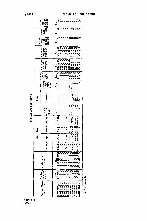
59.15 Construction of metallic lifeboats of class IA. The fol-lowing specifications and schedule of lifeboat material shall be com-plied with unless other arrangements in matters of constructionaldetails, design and strength equivalent in safety and efficiency areapproved by the supervising inspector of the district in which thelifeboat is built.
(a) Keel, stem, and sternpost. The dimensions of bar keels,stems, and sternposts shall be as given in table. The keel, stem, andsternpost shall be in one length except in the case of a boat of stern-frame construction where the stem and keel shall be in one length,scarphed and riveted to the stern frame. The scarph connecting thekeel to the stern frame shall have a length of nine times the thicknessof the keel, or butt welded with suitable reinforcing straps on bothsides.
(b) Shell plating. The gage of shell plating shall be given in tableand shall have a tensile strength of not less than 50,000 pounds persquare inch and an elongation of at least 20 percent in a gage length of8 inches, or of wrought iron having a minimum tensile strength of45,000 pounds per square inch and a minimum elongation of 12 percentin 8 inches; or of other approved metals. When the minimum thick-ness of the steel is less than no. 16 B.W.G. the elongation shall be notless than 15 percent in a gage length of 8 inches. The bottom shellplating shall be increased to gages as shown in table for not less than25 percent of the breadth each side of the keel. Doubling plates ofsuitable size shall be fitted on all steel boats at points where the shellis liable to corrosion from contact with the boat's chocks. All seamand butt laps shall lap at least 11/4 inches. The laps of joints on keel,stem, and sternpost shall be not less than that specified in the table inparagraph (v) of this section.
(c) Riveting. The several plates composing the shell may be joinedtogether either by riveting or welding. Where riveting is employed,it shall be by double riveting. The center of the row of rivets nearest
*tFor statutory and source citations, see note to § 59.1.Page 666[788]
§ 59.14

CHAP. I-BUREAU MARINE INSPECTION, NAVIGATION § 59.15
the edge of a sheet shall be about three-eighths of an inch from theedge. The rivets shall be staggered with not less than 18 rivets to thefoot and such rivets shall have countersunk heads. The diameter ofof the rivets shall be not less than no. 10 B.W.G. The riveting of theshell plating to the keels, stems, and sternposts shall be with button-head rivets of the following diameters, said riveting to be staggeredwith not less than 12 rivets to the foot:
InchBoats 24 feet or under -------------------------------------------- 6Over 24 feet, under 27 ----------------------------------------Over 27 feet, under 32 ----------------------------------------- 6
(d) Welding. Where welding is employed in lifeboat or life raftconstruction it shall be in accordance with the following specificationsfor fusion welding of sheet metal:
(e) Scope. These specifications apply only to the application offusion welding to lifeboats, life rafts, air tanks, and similar vesselssubject to pressures not to exceed 15 pounds per square inch.
(f) Materials-(1) Base metal. The materials shall be steel orwrought iron plates (galvanized) having a thickness of not less thanNo. 18 B.W.G. nor more than three-sixteenths inch.
(2) Filler metal. High-test electrode shall be used to insure aweld which will have an efficiency equal to the strength of the basemetal without reenforcement.
(g) Process. Any process of welding which has been approved bythe Board of Supervising Inspectors may be used in the fabrication oflifeboats and life rafts.
(h) Design of joints. The following joints are acceptable: Buttjoints, flanged joints, or lapped joints, fillet-welded at both edges.
(i) Application of welding. The plates shall be properly formedand secured by jigs, clamps, or other suitable devices to prevent sag-ging or warping. The welder shall use due caution to avoid heatingthe plate to such an extent as to cause it to become distorted or warped.Care shall be taken to insure that the weld has complete fusion, properpenetration to the full thickness, and is reasonably free from porosity.Provision should be made to provide for reasonable expansion andcontraction while the welding is being applied. The weld shall bemachined to a reasonable degree of smoothness and galvanized byspraying with zinc to protect against the weather.
(j) Supervision. Manufacturers who desire to construct lifeboatsor life rafts by means of any process of fusion welding shall submitplans and specifications to the supervising inspector, showing in de-tail the design and methods of construction which they propose toemploy. The plans or specifications shall contain the following data:
(1) Tensile strength of the base metal.(2) Elongation of base metal in a gage length of 4 inches.(3) Trade name of electrode used.4) Elongation of filler metal in a gage length of 2 inches.
(k) Inspection and tests. Inspectors shall have access to lifeboats,life rafts, tanks, etc., under construction in order to ascertain whetherthe material and technique is such as to insure dependable workman-ship. Two tension and two bend test specimens shall be taken from
Page 667[789]

TITLE 46-SHIPPNG
each lifeboat, or life-raft cylinder, constructed by means of fusionwelding. The tension test specimens shall be made with a reducedsection having a gage length of 4 inches. The edges of the bend testspecimens may be parallel. Both tension and bend test specimensshall be made with weld in the center. The reenforcement shall beground off, and the tension test specimen shall show under test atensile strength at least equal to that of the base metal. The bendtest shall be made in a vise in such manner that the fibers of the weldwill be stretched and must withstand being bent to a radius of notless than twice its thickness without showing cracks or flaws. Theinspector making the tests shall satisfy himself that the workmanshipis such that the boat or raft so constructed is at least equal in strengthand dependability to an approved metallic lifeboat or raft of rivetedconstruction.
(1) Floors. Floors shall be fitted in lifeboats 26 feet in length andover, of such dimensions as indicated in table.
The floors shall be flanged 11 inches top and bottom and fastenedto the skin by a single row of rivets three-sixteenths inch in diameterand pitched 3 inches on centers.
Limber holes shall be cut in the floors and so located as to provideefficient draining.
(m) Gunwales. The dimensions of angular steel gunwales shallbe as given in table. The gunwales on each side of the lifeboat shallbe in not more than two pieces. If the gunwales are fitted in twolengths, the butts shall be kept beyond the midship half length of theboat and at opposite ends on each side. The joint may be riveted orwelded, and the backing-up piece shall be angular in section of thethickness of the gunwale, and the length shall be not less than eighttimes the depth of the gunwale. It shall be secured to the sheer strakeby riveting or welding. The gunwales may be of clear grain oak orteak. When made in two lengths the gunwales shall be scarphed witha good long bevel scarph stiffened on the under side by a piece of thesame material at least 2 feet long, 11/4 inches thick, and of the samewidth as the gunwale. The size of gunwales shall be of not less thanthe following dimensions:
Length of boat Depth of Width of
gunwale gunwale
Inches Inches12 feet and not over 18 feet --------------------------- 1% 2,Over 18 and not over 20 feet -------------------------- 1-Y, 24Over 20 and not over 22 feet ------------------------- 2 2YOver 22 and not over 24 feet -------------------------- 24 2%Over 24 and not over 26 feet -------------------------- 23 2YOver 26 feet ---------------------------------------- 2% 2Y
(n) Nosings. The outside of the gunwale angle shall have a nosingfitted to the gunwale of hollow half round 2 inches by one-fourth inch,or the nosing may be of clear grain oak or teak; the flat side of the
Page 668[790]
§ 59.15

CHAP. I-BUREAU MARINE INSPECTION, NAVIGATION § 59.15
nosing on boats not over 20 feet long shall be not less than 1 incheswide and five-eighths inch thick; on boats over 20 feet and not over24 feet it shall be not less than 17/s inches wide and 1 inch thick; onall boats over 24 feet it shall be not less than 21/4 inches wide and 1inch thick.
(o) Gunwale braces. The gunwales shall be secured to the thwartsby steel braces and teed on the thwarts as follows:
Length of boat Size of brace Teed onthwarts
Inches Inches22 feet and under -------------------------------- 5
/6 by 1% 4Over 22 feet ----------------------------------- %by 1% 5
The gunwale braces shall be bolted to thwarts and riveted, or weldedto gunwales.
(p) Breast plates. Breast plates shall be fitted to the stem andsternpost, the thickness of the breast plates to be not less than thethickness of the leg of the gunwale. The depth of the throat of theplate shall be not less than twice the depth of the gunwale.
(q) Thwarts. The dimensions of the thwarts shall be as given intable except that the mast thwarts shall be 2 inches wider and thehole properly reenforced. The number of thwarts shall be not lessthan the following:
Number ofLength of boat: thwarts
Under 18 feet ------------------------------------------------- 418 feet and under 24 ------------------------------------------ 524 feet and under 28 ------------------------------------------ 628 feet and under 32 ------------------------------------------ 7
The thwart ends shall be fitted between flanges and secured theretoby bolts in addition to the bolts through the gunwale braces. TheU flange shall extend inboard to take the brace bolt, which shall be1 inch in width less than the thwart. Stretchers or lower cross seatsof sufficient size and strength shall be fitted in suitable positions forthe efficient rowing of all boats. In boats over 20 feet in lengthwhere lower cross or side seats are required to be fitted, they shallbe well secured and supported. They shall not be placed more than12 inches above the floors.
(r) Stanchions. Stanchions shall be fitted in all lifeboats wherethe unsupported length of the thwarts exceeds 4 feet.
(s) Footings. Footings shall cover the bottom of the boat betweenthe side tanks spaced not more than 2 inches apart. The width ofthe footings shall be not less than 7/2 inches except the center foot-ing, which shall not be less than 92 inches.
The footings shall be made readily portable, and so arranged thatthe plugs are at all times directly accessible without removing anyfitting.
Page 669[791]
§ 59.15
3 0.COmi
E, C
.- v K=, v
sl Ro
zo I "" .0Nc.04"".0"04
C2 I : : : :00 0.000..
~:pi
.l =6 0. 0m o
0
0,
0
z
Ne ge >co g g , 000,g
CD0 .0 0 0 .
C 0 0000 0.0 000
Page 670[7923
CCC CCCCCCC
.0..0..00.00.00.
TITLE 46-SHIPPIrNG
'- ' .. -

CHAP. I-BUREAU MARINE INSPECTION, NAVIGATION § 59.16
(t) Hoisting shackles. Hoisting or lifting shackles when installedin the ends of lifeboats shall have the shackle pins go through thestem and sternpost. Sectional area around the shackle pinhole shallbe at least equal to the area of the shackle specified for the lifeboat.In cases where the lifting shackles are required to be installed insideof the lifeboat, such lifting shackles shall be attached to bracketplates, riveted to stem and sternpost or to rods with bracket platesriveted to keel. The complete unit for each boat of the brackets,rods, and connecting bolts shall be of sufficient strength to sup portthe loaded lifeboat with a safety factor of 6. Hooks may be allowedin lieu of lifting shackles when constructed with a safety factor of6, except when disengaging apparatus is required. Rings or linksshall not be attached to lifeboats for hoisting purposes. When at-tached to the lower tackle blocks they shall be of such strength as toresist the proof load test without set, six times the maximum workingload. The safety factor of 6 referred to is on material having atensile strength of 58,000 to 65,000 pounds per square inch.
(u) Plug. Each lifeboat shall be fitted with an automatic plug.(v) Galvanizing and plating. All steel or iron entering into the
construction of lifeboats shall be galvanized by the hot process.*t[As amended by Supp. I, p. 20, May 28, 1938]
59.16 Construction of wooden lifeboats-(a) Materials. Thetimber shall be of the best quality, well seasoned, free from sapwood,shakes, and objectionable knots. The other materials shall be thebest of their respective kinds.
(b) Framings. Keels, stems, sternposts, aprons, and deadwoodsshall be oak or elm with no short grain or shakes. Parts havingconsiderable curvature shall be oak or hackmatack grown to form.The stem and sternpost are to be rabbeted to take the plank ends andform an efficient stop for the caulk. The depth of the rabbet shallnot exceed the thickness of the plank. Aprons shall be of sufficientsize to insure a 3-inch faying surface and receive the double fasten-ings of the hooded ends. Deadwoods are to be of the same size asthe keel and are to scarph properly with the apron and keelson.The timbers are to be checkedinto the deadwoods and cavities filledwith marine glue to form a water course. Keel and hog piece shallbe elm or oak, and the keel shall be in one length. Scarphs connect-ing the stem and sternpost to the keel may be either vertical orhorizontal. The vertical scarphs shall be secured by five clinchednails, and the horizontal or flat scarphs shall be properly lipped andsecured by at least two through fastenings. Ordinary tenons shallnot be accepted as equivalent to scarphs. Stem bands shall be gal-vanized wrought iron and extend from the breasthook over the stemhead to keel plate or 2 feet abaft the scarph.
(c) Planking. The planking may be of the clincher, carvel, ormultiple-skin types, the carvel and double plank to be recommended,especially the latter when for use on vessels in tropical trades. Inclincher-built boats the extreme breath of the plank is not to exceed51/2 inches; except in the four strakes next to the keel, which maybe as follows: two at 7 inches, one at 61/ inches, and one at 6inches. In boats 18 feet in length and under, these breadths may
*tFor statutory and source citations, see note to § 59.1. Page 671[793]102577---9--T 46----51
TITLE 4 6-SHIPPING
require to be reduced about an inch. The landings shall not beless than seven-eighths inch in breath. The planks should be in aslong lengths as possible, with an efficient shift of butts. There shallbe at least two passing strakes between butts in the same timber space.
(d) Timbers. Timbers shall be elm or oak bent to shape and fittedin one length from gunwale to gunwale, except in the extreme endsof the boats. The spacing of timbers shall not exceed 6 inches centerto center.
(e) Stiffeners. Keelsons shall be in one length and overlap thedeadwoods so as to take all the fastenings of the lifting plates. Asubstantial hardwood chock shall be well secured to the keelson toform a mast step; the keelson shall not be cut for the purpose. Thebilge stringers and risings should be in as long lengths as possible,properly scarphed at the butts, and either through fastened at eachtimber or fastened at each timber with a brass screw. In boats 25feet in length and over, the heads of the timbers are to be carriedup and connected through the sheer strake and gunwale. In allboats, provisions shall be made for double-banking the oars.
(f) Thwarts and stanchions, etc. The number of thwarts shallnot be less than given by the following:
Number of
Lifeboats, length in feet: thwarts18 and under ------------------------------------------------ 4Over 18 and not over 24 --------------------------------------- 5Over 24 and not over 28 ----------------------------------------- 6Over 28 and not over 30 --------------------------------------- 7
The distance of the top of the thwarts below the top of the gunwaleshall be as follows:Lifeboats, length in feet: Inches
22 and under ----------------------------------------------- 9Over 22 and not above 28 ------------------------------------- 10Over 28 and not above 30 ------------------------------------- 11
The thwarts shall be scored over the timbers and directly attachedto the risings by means of 2 screws at each end. In all boats wherethe unsupported length of the thwarts exceeds 5 feet, stanchionswell connected to the thwart and to the side of keelson shall be fitted.The side benches shall be continuous and fitted in as long lengthsas possible; they shall not be removable, but form part of the perma-nent structure of the boat. In boats over 20 feet in length wherelower cross or side seats are required to be fitted, they are to be wellsecured and supported. They shall be placed as low as practicable.Stretchers or lower cross seats of sufficient size and strength are tobe fitted in suitable positions for the efficient rowing of all boats.All lower sheets and bottom boards are to be made readily portable,and so arranged that the plugs are at all times directly accessiblewithout removing any fitting. The plug chains are to be securelyattached to the boat by screws.
(g) Thwart knees. The knees shall be of wrought or stampediron, galvanized 114 inches thick at the thwart. In lifeboats over24 feet in length, the knees shall be double, but, in lieu thereof, ironknees of special design may be adopted. The knees shall be con-nected to the side of the boat and to the thwarts by at least 2 throughfastenings in each arm. Nut and screw bolts are recommended for
Page 672[794]
§ 50.16

CHAP. I-BUREAU MARINE INSPECTION, NAVIGATION § 59.16
the purpose. The bolts should be cupheaded and the nuts have ironplate washers on the under side of the thwarts. Any additionalfastenings may be stout screws, but spike or wire nails are not to beallowed. A hardwood chock 3 inches wide should be fitted betweenknee and side of boat to receive knees and fastenings of sheer strake.Where wood knees are preferred, they should be of oak, ash, elm, orhackmatack grown to form. The fastenings may be galvanizediron, but wire nails shall not be allowed.
(h) Breasthooks. The sides of the boat at the ends shall be wellbound together across the middle line, the breasthooks being ofsufficient number and size, having regard to the dimensions and formof the boat. The arms are to extend along the sides of the boat forat least two timber spaces and are to be through fastened by twobolts in each arm and one through the throat. The breasthooks areto be galvanized iron, or oak or hackmatack grown to form.
(i) Rubbers, filling pieces, bilge keels. Fore and aft rubbers shallbe fitted to all boats. Clincher-built boats are to have filling piecesfor about one-third of the boat's length amidships, fitted to the pro-jecting plank edges from the gunwale to the bilge. In all boatsintended to accommodate more than 60 persons, vertical fendersextending from the gunwale down to the bilge, are to be fitted tofacilitate launching on the high side of a listed ship. These fendersare to be sufficient in number to prevent damage to the boats whenbeing lowered. If the fenders are of wood they are to have copeiron fitted to the outside edges. Particulars of any proposed ar-rangements, including alternatives such as skates or rollers tem-porarily secured to the boat to prevent it from being damaged, andto facilitate launching, are to be submitted for the Board's ap-proval. When bilge keels are fitted, they shall be secured to adoubling plank well fastened to the bottom planking and timbersby brass screws. Bilge-keel fastening shall not penetrate the bot-tom planking. Suitable hand grips shall be made in the bilge keelsfor use in event of capsizing.
(j) Fastenings. Fastenings of the keel, stem and sternpost, aprons,knees, keelson, or deadwood shall be through fastenings whereverpracticable, or long screws. There shall not be less than 6 throughfastenings in the deadwood at each end of the boat. The hog shallbe secured to the keel by galvanized screws 8 inches to 7 inches apart,and the keelson to the keel by through fastenings 24 to 27 inchesapart. In boats over 23 feet in length, the hog may be in two piecesprovided it is scarphed to the satisfaction of the inspector. Boxgunwales shall be through fastened at every timber, and solid gun-wales should be secured with at least four through fastenings be-tween each pair of thwart knees and strengthened by check piecesin way of rowlocks. All gunwales when not fitted in one lengthshall have either lipped or table scarphs, and the scarphs of gunwaleshall be kept if possible beyond midship half length of the boat.Plank fastenings shall be copper of sufficient length and gage, andthose in the plank edges, scarphs, and timbers properly clinched.One fastening is required between the timbers in each edge of each'plank, subject to a maximum spacing of 3 inches in clincher-builtboats.*t [As amended by Supp. I, p. 25, May 28, 1938]
Page 673[795]-
*tFor statutory and source citations, see note to § 59.1.

TITLE 4 6-SHIPPING
59.17 Open boats with internal and external buoyancy; classlB. The internal buoyancy of a wooden boat of this type shall be pro-vided by water-tight air cases, the total volume of which is at leastequal to 72 percent of the cubic capacity of the boat. The externalbuoyancy may be of cork or of any other equally efficient material,but such buoyancy shall not be secured by the use of rushes, corkshavings, loose granulated cork, or any other loose granulated sub-stance, or by any means dependent upon inflation by air. If thebuoyance is of cork, its volume, for a wooden boat, shall not be lessthan thirty-three thousandths of the cubic capacity of the boat; ifof any material other than cork, its volume and distribution shallbe such that the buoyancy and stability of the boat are not less thanthat of a similar boat provided with buoyancy of cork. The buoy-ancy of a metal boat shall be not less than that required above fora wooden boat of the same cubic capacity, the volume of the air casesand external buoyancy being increased accordingly. Boats of thisclass shall have a mean sheer equal to at least 4 percent of theirlength.*t
59.18 Lundin and Lane lifeboats. (a) Lundin decked lifeboatsand Lane decked metallic lifeboats shall be accepted as equivalent toclass 1A lifeboats and shall be rated and accepted as lifeboats underdavits, and may be placed in nests of two under a single pair of davits,but such nesting shall not commence until each set of davits as requiredby law is first fitted with a required lifeboat. They shall be fullyequipped as lifeboats as required by this part and shall be measured inaccordance with the following formula:
Cubic capacity =L X B X D X 0.9 cubic footWhere
L=length over all, in feet.B=width over fenders, in feet.D = depth from top of keel to top of gunwale, in feet.Example: 28 X 9.5 feetX 2.5 feetX 0.9=598.5 cubic feet.Allow 10 cubic feet to a person, 598.5 - 10=59 persons.
Provided, That when the Lundin decked lifeboats and Lane deckedmetallic lifeboats are loaded to their full capacity the water-tight deckshall be not less than 2 inches above the load water line, and shall havean excess buoyancy in air space and fenders of not less than 25 percentof the combined weight of boat and load. Not less than 10 percentof the total buoyancy shall be in fenders of buoyant material firmlysecured to the outside of the boat.
The following example is given in explanation of the above proviso:Example: 26 feet, 50 persons, Lundin decked lifeboat or Lane decked
metallic lifeboat.Height of load water line, 15 inches. Required height of inner
deck=15 inches+2 inches=17 inches. Combined weight of boat andload (each person allowed figured at 165 pounds), 12.250 poundsExcess buoyancy required in air space and fenders above = 0.25 X 12,250=3,062.5 pounds. Total buoyancy required, i. e., buoyancy of airspace below water-tight deck plus buoyancy of entire fenders= 12,250
*tFor statutory and source citations, see note to § 59.1.Page 674[796]
§ 59.17

CHAP. I-BUREAU MARINE INSPECTION, NAVIGATION § 59.20
+3,062.5=15,312.5 pounds. Buoyancy required in entire fenders-0.10 X 15,312.5= 1,531.25 pounds.
The carrying capacity of the Lundin power lifeboat shall be deter-mined by the same rule as the Lundin decked lifeboat and Lane deckedmetallic lifeboat, with proper reduction for the weight and space usedfor the motors, tanks for fuel, and wireless apparatus.
(b) The carrying capacity of the Lundin housed lifeboat shall bedetermined by the same rule as the Lundin decked lifeboat and Lanedecked metallic lifeboat. Lundin semidecked lifeboats shall be ac-cepted as equivalent to class 1A lifeboats and shall be rated andaccepted as lifeboats under davits, and may be placed in nests of twounder a single pair of davits, but such nesting shall not commenceuntil each set of davits as required by law is first fitted with a requiredlifeboat. They shall be fully equipped as lifeboats as required by thispart, and shall be measured in accordance with the following formula:
Whlere Cubic capacity=L X B X DX 0.9 cubic foot
L= length over all, in feet.R= width over fenders, in feet.D = depth from top of keel to top of gunwale, in feet.Example: 20 feet X 7 feet X 2 feet X 0.9 252 cubic feet.Allowing 10 cubic feet to a person, 252 +10 = 25 persons.
Provided, That the length of the Lundin semidecked lifeboat does notexceed 24 feet; that the above boat is provided with independent airtanks, placed at the sides of the boat, built in accordance with the gen-eral rules for air tanks of lifeboats and with a capacity of not less than11/2 cubic feet for each person allowed; that the above boat is providedwith built-in water-tight compartments, one in each end, and providedwith a water-tight manhole, and that not less than 10 percent of thevolume of the displacement to the load-water line shall be in fendersof buoyant material firmly secured to the outside of the boat.
The Ludin open lifeboat with balsa-wood fenders, 24 feet in length,7 feet 1 inch in breadth inside fender, 8 feet in breadth outside fender,and 3 feet 2 inches in depth, shall be allowed to carry 40 persons. Thenumber of persons allowed to be carried on boats of this type of otherdimensions shall be determined, after an actual demonstration, by thesupervising inspector of the district in which the boat is accepted.*t
59.19 Boats equivalent to boats of class lB. Any type of boatmay be accepted as equivalent to a boat of class 1B after blue printsand specifications have been submitted and a practical demonstra-tion of a full-size boat is witnessed by the Board of SupervisingInspectors.*t
59.20 Pontoon boats in which persons can not be accommodatedbelow the deck, having a well deck and fixed water-tight bulwarks;class 1C. The area of a well deck of a boat of this type shall be atleast 30 percent of the total deck area. The height of the well deckabove the water line at all points shall be at least equal to one-halfpercent of the length of the boat, this height being increased to 1/2percent of the length of the boat at the ends of the well. The free-board of a boat of this type shall be such as to provide for a reservebuoyancy of at least 35 percent.*t
*tFor statutory and source citations, see note to § 59.1. Page 675[7973

TITLE 4 6-SHIPPING
59.21 Boats of the second class. The standard types of boats ofthe second class shall satisfy the conditions set forth in §§ 59.22-59.35.*t
59.22 Open boats having the upper part of the sides collapsible;class 2A. A boat of this type shall be fitted both with water-tight aircases and with external buoyancy, the volume of which, for eachperson which the boat is able to accommodate, shall be at least equalto the following amounts: Air cases, 15/1o cubic feet; external buoyancy(if of cork) 3~o cubic foot. The minimum freeboard of boats of this
typeis ixe in relation to their length; it is measured vertically tothie top of the solid hull at the side amdships, from the water levelwhen the boat is loaded. The freeboard in fresh water shall not beless than the following amounts:
Length of the Minimumboat freeboard
Feet Inches26 828 930 10
The freeboard of boats of intermediate lengths is to be found byinterpolation.*t
59.23 Pontoon boats having a well deck and collapsible bul-warks; class 2B. All the conditions laid down for boats of type 1Care to be applied to boats of this type, which differ from those oftype 1C only in regard to the bulwarks.*t
59.24 Pontoon boats in which persons can not be accommodatedbelow deck, having a flush deck and collapsible bulwarks; class 2C.The minimum freeboard of boats of this type is independent of theirlengths and depends only upon their depth. The depth of the boatis to be measured vertically from the underside of the garboardstrake to the top of the deck at the side amidships, and the freeboardis to be measured from the top of the deck at the side amidships tothe water level when the boat is loaded. The freeboard in freshwater shall not be less than the following amounts, which are appli-cable without correction to boats having a mean sheer equal to 3percent of their length:
Depth of Minimumboat freeboard
Inches Inches12 2Y18 3Y20 5%30 6%
*tFor statutory and source citations, see note to § 59.1.Page 676[798]
§ 59.21

CHAP. I-BUREAU MARINE INSPECTION, NAVIGATION § 59.28
For intermediate depths the freeboard is obtained by interpola-tion. If the sheer is less than the standard sheer defined above, theminimum freeboard is obtained by adding to the figures in the tableone-seventh of the difference between the standard sheer and theactual mean sheer measured at the stem and sternpost. No deduc-tion is to be made from the freeboard on account of the sheer being
r reater than the standard sheer or on account of the camber of theeck. Pontoon lifeboats may be built of wood or metal. If con-
structed of wood, they shall have the bottom and deck made of twothicknesses with textile material between; if of metal, they shall bedivided into water-tight compartments, with means of access toeach compartment.*t
59.25 Arrangements for clearing pontoon lifeboats of water.All pontoon lifeboats shall be fitted with efficient means for quicklyclearing the deck of water. The orifices for this purpose shall besuch that the water can not enter the boat through them when theyare intermittingly submerged. The number and size of the orificesshall be determined for each type of boat by a special test. Forthe purpose of this test the pontoon boat shall be loaded with aweight of iron or bags of sand equal to that of its complement ofpersons and equipment. In the case of a boat 28 feet in length, 2tons of water shall be cleared from the boat in a time not exceedingthe following: type 1C, 60 seconds; type 2B, 60 seconds; type 2,20 seconds.*t
59.26 Type of boat equivalent to boat of class 2. Any type ofboat may be accepted as equivalent to a boat of class 2 after blueprints and specifications have been submitted to, and a practicaldemonstration of a full-size boat has been witnessed by, and the typeof boat has been approved by, the Board of Supervising Inspectors.*t
59.27 Brude lifeboat. Lifeboats of the Brude type, of the sizesspecified below, for use on cargo steamers, shall be allowed thefollowing rating:
Number ofpersons car-
Length Height Width ried and al-lowed on cargo
steamers
Feet Ft. in. Ft. in.18 8 0 8 0 3414 6 9 6 9 17
The number of persons allowed to be carried by boats of this typeof other dimensions shall be determined, after an actual demonstra-tion, by the supervising inspector of the district in which the boatis accepted.*t
59.28 Capacity and allowance of Engelhardt collapsible life-boats. Engelhardt collapsible lifeboats may be carried as lifeboats
*tFor statutory and source citations, see note to § 59.1. Page 677[799]
TITLE 4 6-SHIPPING
and rated as class 2C, and shall be fully equipped as lifeboats asrequired by this part. The cubic capacity of Engelhardt collapsiblelifeboats shall be determined in accordance with the following rule:Measure in feet and fractions of a foot the length and breadth out-side of canvas extension and the depth inside at the place of mini-mum depth taken from the inside of the bottom planking of thebottom to the top of gunwhale when extended. The product of thesedimensions multiplied by 0.7 shall be deemed the capacity in cubicfeet.*t
59.29 Newcomb inclosed lifeboat. Lifeboat of this type, 26 feetin length, 6 feet 4 inches in breadth, and 3 feet 4 inches in depth,when constructed in accordance with the rules for lifeboats, shall beallowed to carry 25 persons. The number of persons allowed to becarried by boats of this type of other dimensions shall be determined,after an actual demonstration, by the supervising inspector of thedistrict in which the boat is accepted.*t
59.30 Air tanks of lifeboats. All lifeboats contracted for afterSeptember 30, 1912, shall have not more than 50 percent of the airtank capacity in the ends of the boat and the remaining capacityshall be located in the side tanks. After June 20, 1912, the air tanksof all lifeboats shall be entirely independent of the hull or otherconstruction and shall be of suitable noncorrosive material and of acapacity of not less than 1.5 cubic feet for each person allowed inmetallic boats and not less than 1 cubic foot for each person allowedin wooden boats: Provided, That in all metallic boats constructedand inspected on and after March 1, 1931, there shall be at least1 cubic foot for each person allowed in addition to sufficient air-tankcapacity to float the boat (including its equipment), when filled withwater. Such air tanks shall be firmly and securely fastened in thehull, and in suc*h manner as will allow them to be temporarily re-moved, and in no case shall the tanks be punctured or opened forsuch fastenings. The tops of such tanks shall be thoroughly pro-tected by a grating or platform or by the thwarts or seats. Suchair tanks of 6 cubic feet or less shall be constructed of material of athickness not less than No. 22 B.W.G.; from 6 cubic feetto and including 15 cubic feet, of a thickness not less thanNo. 20 B.W.G.; and all air tanks of more than 15 cubicfeet capacity shall be of a thickness not less than No. 18B.W.G. All joints of air tanks shall be properly doubleriveted and tightly calked or securely hook jointed and efficientlysoldered or properly and securely welded, and such air tanks shallbe located in such a manner that will permit the lifeboat to be on asnear an even keel as possible when flooded with water. The cubicalcontents of air space of air tank shall be stamped on the tank wheresame can be seen when air tank is placed in boat. All air tanks shallbe fitted with a connection of one-half inch outside diameter for test-ing purposes. Before any lifeboat is passed and accepted, the airtanks thereof shall be tested in the presence of an inspector of thisservice by an air pressure of not more than 1 pound to the squareinch. At each subsequent annual inspection, or oftener if in the
*tFor statutory and source citations, see note to § 59.1.Page 678[800]
§ 59.29

CHAP. I-BUREAU MARINE INSPECTION, NAVIGATION § 59.31
opinion of the inspectors it is necessary or desirable, the inspectorsshall satisfy themselves that the tanks are in good condition, butpressure need not be applied unless the inspectors are in doubt re-aarding the efficiency of the tanks. This does not take from theinspectors the right and authority to satisfy themselves at any time,either by examination or pressure, as to the condition of tanks.*t
59.31 Cubic capacity of open boats of the first class. (a) Thecubic capacity of an open boat of type 1A or 1B shall be determinedby Stirling's (Simpson's) rule or by any other method, approvedby the Board of Supervising Inspectors, giving the same degree ofaccuracy. The capacity of a square-sterned boat shall be calculatedas if the boat had a pointed stern.
(b) For example, the capacity in cubic feet of a boat, calculatedby the aid of Stirling's rule, may be considered as given by thefollowing formula:
Capacity= 12 (4A+2B-4C)
1 being the length of the boat in feet from the inside of the plankingor plating at the stem to the corresponding point at the sternpost;in the case of a boat with a square stern, the length is measured tothe inside of the transom. A, B, C denote, respectively, the areas ofthe cross sections at the quarter length forward, amidships, and thequarter length aft, which corres--ond to the three points obtainedby dividing I into 4 equal parts. (The areas corresponding to thetwo ends of the boat are considered negligible.) The areas A, B, Cshall be deemed to be given in square feet by the successive applica-tion of the following formula to each of the three cross sections:
hArea=h (a+4b--2c±4d e)
A being the depth measured in feet inside the planking or platingfrom the keel to the level of the gunwale, or, in certain cases, to alower level, as determined hereafter. a, b, c, d, e denote the horizon-tal breadths of the boat measured in feet at the upper and lowerpoints of the depth and at the three points obtained by dividing I intofour equal parts (a and e being the breadths at the extreme points,and o at the middle point, of h).
(c) If the sheer of the gunwale, measured at the two points situ-ated at a quarter of the length of the boat from the ends, exceeds 1percent of the length of the boat, the depth employed in calculatingthe area of the cross sections A or C shall be deemed to be the depthamidships plus 1 percent of the length of the boat.
(d) If the depth of the boat amidships exceeds 45 percent of thebreadth, the depth employed in calculating the area of the midshipcross section B shall be deemed to be equal to 45 percent of thebreadth; and the depth employed in calculating the areas of thequarter-length sections A and C is obtained by increasing this lastfigure by an amount equal to 1 percent of the length of the boat,
*tFor statutory and source citations, see note to § 59.1. Page 679
[8011102 77--39-TITLE 46 -52

TITLE 4 6-SHIPPING
provided that in no case shall the depths employed in the calcula-tion exceed the actual depths at these points.
(e) If the depth of the boat is greater than 4 feet, the number ofpersons given by the application of this section shall be reduced inproportion to the ratio of 4 feet to the actual depth, until the boathas been satisfactorily tested afloat with that number of persons onboard, all wearing life jackets.
(f) The following rule may be used, provided it does not give agreater capacity than that obtained by the above method: Measurethe length and breadth outside of the planking or plating and thedepth inside at the place of minimum depth. The depth used in cal-culating shall not in any case exceed 45 percent of the breadth. Theproduct of these dimensions multiplied by 0.6 resulting in the nearestwhole number shall be deemed the capacity in cubic feet. To deter-mine the number of persons a boat may carry, divide the result by10 for ocean steam vessels.
Example: The carrying capacity of a boat 22 feet in length, 6 feetin breadth and 21/2 feet in depth shall be determined as follows:
22X6X2Y2 X0.6 198 1 r10 -f--19 persons
In all cases the vessel owner has the right to require that the cubiccapacity of the boat shall be determined by exact measurement.
(g) The cubical capacity of a motor boat shall be obtained bydeducting from the gross capacity a volume equal to that occupiedby the motor and its accessories, and, when carried, the wirelessinstallation and searchlight with their accessories.
(h) The cubical capacity of a lifeboat propelled by hand-operatedpropeller shall be obtained by deducting from the gross capacity avolume equal to that occupied'by such device.
(i) When computing the air-tank requirements, the weight ofthe motor and its accessories, and, when carried, the wireless installa-tion and searchlight with their accessories shall be carefully con-sidered in the calculation and allowance made for the extra buoyancyrequired for such weight.*t [As amended by Supp. I, p. 27, May 28,1938]
59.32 Deck area of pontoon boats and open boats of the secondclass. (a) The area of the deck of a pontoon boat of type 1C, 2B,or 2C shall be determined by the method indicated below or by anyother method giving the same degree of accuracy. The same ruleis to be applied in determining the area within the fixed bulwarks ofa boat of type 2A.
(b) For example, the surface in square feet of a boat may bedeemed to be given by the following formula:
1Area=1 (2a+ 1.5b + 4c+1.5d2e)12
1 being the length in feet from the intersection of the outside of theplanking with the stem to the corresponding point at the sternpost,a, b, c, d, e, denote the horizontal breadths in feet outside the plank-
Page 680 *tFor statutory and source citations, see note to § 59.1.[8021
§ 59.32

CHAP. I-BUREAU MARINE INSPECTION, NAVIGATION § 59.35
ing at the points obtained by dividing 1 into four equal parts andsubdividing the foremost and aftermost parts into two equal parts(a and e being the breadths at the extreme subdivisions, o at themiddle point of the length, and b and d at the intermediate points.)
(c) The minimum cubic capacity of open boats of type 1A shallbe not less than 10 cubic feet for each person.
(d) The minimum cubic capacity of open boats of type 2B shall benot less than 9 cubic feet for each person.
(e) The minimum deck capacity for open boats of type 2A andpontoon boats of type 2C shall be not less than 3/2 square feet, andof pontoon boats of types 2B and 1C not less than 31/4 square feet.
(f) If after a practical demonstration it is found that there isa greater seating capacity than is allowed by the above, the numberof square feet may be reduced, but never less than 3 square feet foreach person.*t
59.33 Capacity limits. (a) Pontoon boats and pontoon rafts shallnever be marked with a number of persons greater than that obtainedin the manner specified in this section. This number shall be reduced:
(1) When it is greater than the number of persons for which thereis proper seating accommodation, the latter number being determinedin such a way that the persons when seated do not interfere in anyway with the use of the oars.
(2) When in the case of boats other than those of the first two sec-tions of the first class, the freeboard, when the boat is fully loaded,is less than the freeboard laid down for each type respectively. Insuch circumstances the number shall be reduced until the freeboard,when the boat is fully loaded, is at least equal to the standard free-board laid down above.
(b) In boats of types 1C and 2B the raised part of the deck atthe sides may be regarded as affording seating accommodation.*t
59.34 Equivalents for and weight of the persons. (a) In testfor determining the number of persons which a boat or pontoon raftcan accommodate each person shall be assumed to be an adult personwearing a life preserver.
(b) In verifications of freeboard the pontoon boats shall be loadedwith a weight of at least 165 pounds for each adult person that thepontoon boat is authorized to carry.
(c) In all cases two children under 12 years of age shall bereckoned as one person.*t
59.35 Numbering and marking of lifeboats. (a) The numberof each lifeboat shall be plainly marked or painted on each sideof the bow in figures 3 inches high; and, where lifeboats are carriedon both sides of a vessel, the odd-numbered boats shall be stowedon the starboard side and even-numbered boats on the port side;i. e., lifeboat No. 1 shall be forward on the starboard side, and lifeboatNo. 3 next abaft lifeboat No. 1; lifeboat No. 2 shall be forward on theort side and lifeboat No. 4 next abaft lifeboat No. 2, etc. Where
ifeboats are nested, the lifeboat under lifeboat No. 1 shall benumbered 1A, the lifeboat under lifeboat No. 2 shall be numbered2A, etc.
*iFor statutory and source citations, see note to § 59.1. Page 681[803]

TITLE 4 6-SHIPPING
(b) The cubical contents and number of persons allowed to becarried on each lifeboat shall be plainly marked or painted on eachside of the bow in letters and numbers 1 inches high. In addition,the number of persons allowed shall be plainly marked or paintedon the top of at least two of the thwarts in letters and numbers 3inches high. Such letters and numbers shall be dark on a lightground or light on a dark ground.*t [As amended by Supp. I, p. 27,May 28, 1938]
59.36 Lifeboats and liferafts kept clear for launching. Thedecks on which lifeboats of any class or liferafts are carried shallbe kept clear of freight or any other obstruction that would interferewith the immediate launching of the lifeboats or liferafts.*t
59.37 Boat-davit falls and receptacles therefor. (a) It shall bethe duty of the master or officer in charge of all vessels to see thatthe boat-davit falls shall at all times be in readiness for immediateuse, and protected from ice, and not painted, and such boat-davit fallson all boats not swung out at boat drills shall be cast loose and over-hauled; and it shall be unlawful to stow in any lifeboat articles otherthan those required by law and regulations. On all steamers over1,000 gross tons, covered tubs boxes, or reels shall be provided inwhich to stow away the boat-davit falls.
(b) Where more than one lifeboat is served under one set ofdavits, means shall be provided that will prevent davit tackles fromtwisting or capsizing, and that will permit the tackles being readilyrounded up for the purpose of launching the remaining lifeboatsunder such davits: Provided, That when davits are equipped withseparate tackles for each boat, such nontwisting and noncapsizingdevice is not required.*t
59.38 Care of lifeboats. Lifeboats shall be stripped, cleaned,thoroughly overhauled, and painted at least once in every year.*t
59.39 Tests of boats at annual inspection. The inspectors shallsatisfy themselves that every lifeboat, together with its equipment,of all vessels, is in every respect in good condition and ready for im-mediate use. Every lifeboat, with its required equipment, of passen-ger vessels, shall be lowered to near the water and loaded to its al-lowed capacity, evenly distributed throughout its length, and thenlowered into the water afloat. In making this test, persons or dead-weight may be used. If persons are used, the weight of each personshall average at least 140 pounds. When deadweight is used, theweight shall be equivalent to at least 140 pounds for each personallowed.*t
59.40 Size of boats. (a) No lifeboat for use on ocean steam ves-sels shall be of less than 180 cubic feet capacity, except that allpleasure steamers, and other steamers not exceeding 1,000 gross tonslimited by their certificate of inspection to routes not exceeding 20nautical miles offshore shall only be required to carry one lifeboatof 180 cubic feet capacity. Nothing, however, shall exempt suchsteamers from carrying the aggregate cubic capacity required bythis part and Part 60. The minimum capacity of lifeboats for thisclass of vessels shall be 125 cubic feet.
*tFor statutory and source citations, see note to § 59.1.Page 682[804]
§ 59.36

CHAP. I-BUREAU MARINE INSPECTION, NAVIGATION § 59.43
(b) The supervising inspector of the district may, in exceptionalcases, permit lifeboats of less than 180 cubic feet as a substitute forsaid boat on steamers where the crew is insufficient to properly handlea boat of that size, or where there is lack of space to properly carryso large a lifeboat, but in every such case the steamer shall be pro-vided with one or more lifeboats efficient in character and largeenough to carry every person on board, and in no case shall the life-boat be of less capacity than 125 cubic feet.*t
59.41 Handling of the boats and rafts. All the boats and raftsshall be stowed in such a way that they can be launched in the shortestpossible time and that, even under unfavorable conditions of listand trim from the point of view of the handling of the boats andrafts, it may be possible to embark in them as large a number ofpersons as possible. The arrangements shall be such that it may bepossible to launch on either side of the vessel as large a number ofboats and rafts as possible. Where practicable, lifeboat chocks onpassenger vessels shall be so fitted that the lifeboats they serve shallnot require lifting before launching. At least once in each intervalof not longer than 3 months, the master of every inspected pas-senger vessel shall drill and exercise every member of the crew, ex-cept females, in pulling oars in the ship's lifeboats. In addition, thecrew of the motor-propelled boats shall demonstrate their ability inthe working of the engine and handling of the boat under power.*t[As amended by Supp. I, p. 27, May 28, 1938]
59.42 Liferafts: drawings, specifications, name plate, and howmarked. (a) All liferafts shall be substantially constructed in ac-cordance with drawings, or blueprints, and specifications approvedby the Board of Supervising Inspectors.
(b) Builders of lferafts shall furnish the supervising inspectorof the district in which the life rafts are built drawings, or blue-prints, and specifications showing and explaining the constructionof same and showing the tensile strength and ductility of the metalused. Liferafts may be constructed of steel having a minimumtensile strength not less than 50,000 pounds per square inch and anelongation of at least 20 percent in a gage length of 8 inches; orof wrought iron having a minimum tensile strength of 452000 poundsper square inch and a minimum elongation of 12 percent m 8 inches;or of other approved metals. Where steel is used and a minimumthickness of the metal is less than No. 16 B. W. G., the elongationshall not be less than 15 percent in a gage length of 8 inches.
(c) Builders of liferafts shall affix a plate or other device to eachliferaft, having thereon the builder's name, number of raft, date ofconstruction of raft, cubical contents of raft, and number of personssaid raft will carry, as determined by the rules of the Board ofSupervising Inspectors.
(d) There shall be stenciled in a conspicuous place on each liferaftnow in use the number of persons said raft can carry, as hereinafterprovided.*t [As amended by Supp. I, p. 28, May 28, 1938.]
59.43 Inspection of liferafts when built. Supervising inspec-tors of districts where liferafts are built shall detail an assistant or
*tFor statutory and source citations, see note to § 59.1. Page 683[80-5]

TITLE 46-SHIPPING
local inspector to any place where life rafts are being built, whose dutyit shall be to carefully inspect and examine the construction of suChliferafts, and he shall satisfy himself that such liferafts are con-structed in accordance with the drawings, or blue prints, and specifica-tions furnished by the builders. When the assistant or local inspectorapproves the construction of the raft he shall stamp his initials, to-gether with the letters U. S. I., on a blank space on the plate requiredto be affixed to the raft by the builder. The initials of the assistant orlocal inspector shall be satisfactory evidence to all parties interestedthat the raft has been constructed in accordance with the drawings, orblue prints, and specification on file. This section shall apply to allliferafts constructed after June 30, 1912.*t
59.44 Construction of rafts of the catamaran type. All metalliferaft cylinders of more than 15 feet in length or of more than 16inches in diameter shall be constructed of metal not less than No. 18B. W. G. No liferaft cylinders shall be of less thickness of metalthan No. 20 B. W. G.
The retaining bands which secure the cylinders to the frames shallbe made in halves, so that the cylinders may be detached without diffi-culty and without disassembling the body of the raft, for the purposeof inspection, cleaning, and painting, as required by § 59.46. Woodenguards and gunwales shall be secured to the retaining bands by angle-iron clips or by the jaws of the retaining bands. Iron rods extendingacross the raft at top and bottom shall pass through the gunwale andits securing clips or jaws at each end of the raft. The ends of the rodsshall be properly secured with a screw nut inside and outside of thegunwale.
All such cylinders shall be divided by water-tight bulkheads intonot less than three compartments of equal lengths. Cylinders over 9feet in length shall be divided into equal lengths by water-tight bulk-heads into not less than one compartment for every 3 feet of its length.One of such bulkheads shall be at the extreme end of each cylinderor as near thereto as the flange of cone or bumped ends will permit.Each compartment shall be provided with a suitable air-pump con-nection of one-half inch outside diameter, fitted with airtight cap.
Only countersunk-headed rivets shall be used in the construction ofmetallic liferafts.
All seams and joints shall be properly double riveted.The above provisions of this section shall take effect only as to life-
rafts constructed after December 31, 1908.The circumferential as well as the longitudinal seams of liferaft
cylinders shall be riveted and tightly calked, or securely hook jointedand efficiently soldered, or properly and securely welded on rafts con-structed after June 30, 1905. Such longitudinal seams shall be securedby not less than 12 rivets to each foot, circumferential seams by not lessthan 10 rivets to each foot, and bulkheads by not less than 8 rivets toeach foot. Bulkhead flanges may be single riveted. The diameter ofshank of rivets shall be not less than No. 10 B. W. G.
The framework connecting the cylinders of metallic liferafts shallbe substantially built and capable of resisting the strain which tends
*tFor statutory and source citations, see note to § 59.1.Page 684[806]
§ 59.44

CHAP. I-BUREAU MARINE INSPECTION, NAVIGATION § 59.48
to break the cylinders apart when the raft is broadside on in surf orseaway.*t
59.45 Tests of air tanks of Iiferafts. Before any liferaft ispassed and accepted the air tanks thereof shall be tested in the pres-ence of an inspector of this Bureau by an air pressure of not more than1 pound to the square inch. At each subsequent annual inspection oroftener, if in the opinion of the inspectors it is necessary or desirable,the inspectors shall satisfy themselves that the tanks are in good con-dition, but pressure need not be applied unless the inspectors are indoubt regarding the efficiency of the tanks. This does not take fromthe inspectors the right and authority to satisfy themselves at anytime, either by examination or pressure, as to the condition of thetanks.*t
59.46 Care of liferafts. All liferafts shall be stripped, cleaned,painted, and thoroughly overhauled at least once in every year, andinspectors shall carefully examine at all inspections the material whichsupports the platform of all life floats in order to determine to theirsatisfaction that the strength is maintained. If it is found that de-terioration has begun it shall be corrected even to the extent of requir-ing the renewal of the platform-supporting device.*t
59.47 Approved liferafts. Any type of liferafts approved bythe Board of Supervising Inspectors shall be considered as equivalentto the standard raft above specified.*t
59.48 Clark liferafts. Clark liferafts shall be constructed,tested, and rated in accordance with the following specifications:
(a) All cylinders of more than 16 inches in diameter shall be con-structed of metal not less than No. 18 B. W. G., and no cylinder shallbe of less thickness of metal than No. 20 B. W. G. Cylinders shall beprovided with a suitable air-pump connection of one-half inch outsidediameter, fitted with air-tight cap.
(b) The inspection of liferafts shall include the testing of eachcompartment by air pressure.
(c) The circumferential as well as the longtitudinal seams of cylin-ders shall be riveted and tightly calked, or securely hook jointed andefficiently soldered, or properly and securely welded. Such longitu-dinal seams shall be secured by not less than 12 rivets to each foot,circumferential seams by not less than 10 rivets to each foot, andbulkheads by not less than 8 rivets to each foot.
(d) Only countersunk-headed rivets shall be used in the construc-tion of cylinders. The diameter of shank of rivets shall be not lessthan No. 10 B. W. G.
(e) The framework connecting the cylinders shall be substantiallybuilt and capable of resisting the strain which tends to break the raftapart when the raft is broadside on in surf or when in seaway.
(f) There shall be allowed for each person carried not less than3 cubic feet of air space and a deck area of not less than 4 square feet.
(g) On and after May 1, 1917, the iron or steel bolts and nuts usedin the construction of Clark rafts for service on salt water shall begalvanized. Nuts shall not be countersunk in the wood frame, butshall be protected by a wooden batten properly fitted over the nutsand fayed neatly to the frame.*t
*tFor statutory and source citations, see note to § 59.1. Page 685[807]

TITLE 4 6-SHIPPING
59.50 Capacity and allowance of liferafts. (a) No type of raftmay be approved unless it satisfies the following conditions:
(1) It should be reversible and fitted with bulwarks of wood,canvas, or other suitable material on both sides. These bulwarksmay be collapsible and shall be not less than 4 inches high.
(2) It should be of such size, strength, and weight that it can behandled without mechanical appliances, and, if necessary, be thrownfrom the vessel's deck.
(3) It should have not less than 3 cubic feet of air cases or equiv-alent buoyancy for each person whom it can accommodate.
(4) It should have a deck area of not less than 4 square feet foreach person whom it can accommodate, and the platform should benot less than 6 inches above the water level when the raft is loaded.
(5) The air tanks or equivalent buoyancy should be placed as nearas possible to the sides of the raft.
(b) Rafts shall never be allowed a greater number of persons thanfor whom there is proper seating capacity without interfering withthe use of the oars. At least one-half of the number of liferafts onall steam vessels shall each have a capacity exceeding 15 persons.Tule and all other types of liferafts shall meet the requirementsherein specified.*t
59.52 Equipment for liferafts. Liferafts shall be equipped asfollows:
(a) Distress signals. One watertight metal case containing 12self-igniting red lights of same character as distress lights requiredfor lifeboats, the container to be of the same material and constructionas required for lifeboats.(b) Drinking cups. Two enameled drinking cups.(c) Life line. One life line properly secured entirely around the
sides and ends of the raft, festooned to the gunwales in bights notlonger than 3 feet with seine float in each bight.
(d) Matches. One box of friction matches in a water-tight con-tainer.
(e) Oars. Four oars.(f) Painter. One painter of manila rope not less than 23/4 inches
in circumference and a length not less than three times the distancebetween the boat deck and the light draft.
(g) Provisions. One airtight receptacle containing 2 pounds ofprovisions for each person. These provisions may be of hard breador its equivalent in any approved emergency ration of cereal orvegetable compound. No meat or other ration requiring saline pre-servative shall be allowed. The receptacle shall be of metal fittedwith an opening in the top not less than 5 inches in diameter properlyprotected by a screw cap made of heavy cast brass with machinethread and an attached double toggle, seating to a pliable rubber orfelt gasket, which shall insure a tight joint.
(h) Rowlocks. Five rowlocks attached by separate chains.(i) Sea anchor. One sea anchor constructed of good quality can-
vas or other satisfactory material; and, if of circular pattern, shallbe not less than 2 feet in diameter.
*tFor statutory and source citations, see note to § 59.1.Page 686[808]
§ 59.50
CHAP. I-BUREAU MARINE INSPECTION, NAVIGATION § 59.54a
(j) Self-igniting water light. One self-igniting water light ofapproved type. (See § 59.57.)
(k) Storm oil. One container holding 1 gallon of vegetable oranimal oil so constructed that the oil can be easily distributed on thewater, and so arranged that it can be attached to the sea anchor.
(1) Water breakers. Wooden breakers or suitable tanks fitted withspigots for drawing water and containing at least 1 quart of waterfor each person.*t [As amended by Supp. I, pp. 14, 19, May 28,1938]
59.53 Certificated lifeboat men; manning of the boats. Thereshall be for each boat or raft a number of lifeboat men at least equalto that specified as follows: If the boat or raft carries less than41 persons, the minimum number of certificated lifeboat men shallbe 2, if the boat or raft carries 41 persons and less than 61 personsthe minimum number of certificated lifeboat men shall be 3; ifthe boat or raft carries from 61 persons to 85 persons, the minimumnumber of certificated lifeboat men shall be 4; if the boat or raftcarries more than 85 persons, the minimum number of certificatedlifeboat men shall be 5.
The allocation of the certificated lifeboat men to each boat andraft remains within the discretion of the master according to thecircumstances.*t [As amended by Supp. I, p. 29, May 28, 1938]
CRoss REFERENCE: For qualifications and examination of certificated lifeboatmen, see § 138.4.
59.54 Manning of the boats. (a) A licensed deck officer or a cer-tificated lifeboat man shall be placed in charge of each boat or liferaft by the master, and a second in command shall also be nomi-nated by the master. The person in charge shall have a list of itscrew, and shall see that the men placed under his orders areacquainted with their several duties.
(b) A man capable of working the motor shall be assigned toeach motor boat by the master.
(c) A man capable of working the wireless and search-light instal-lations shall be assigned to boats carrying this equipment by themaster.
(d) The duty of seeing that the lifeboats, life rafts and buoyantapparatus and other life-saving apparatus are at all times readyfor use shall be assigned to one or more officers.*t [As amended bySupp. I, p. 30, May 28, 1938]
59.54a Buoyant apparatus-(a) Definition. Buoyant apparatusis defined as buoyant deck seats, buoyant deck chairs, and light floatsor other apparatus, having buoyancy except lifeboats, life buoys,and life preservers, and no buoyant apparatus shall be approvedwhich requires any adjustment or preparation.
(b) General requirements. Buoyant apparatus shall conform tothe following general requirements:
(1) Its construction shall be of material and workmanship ade-quate for the purpose intended.
(2) It shall be effective and stable floating either side up.(3) It shall have a line securely becketed around the outside and/or
pendants to accommodate the number of persons allowed.
*tFor statutory and source citations, see note to § 59.1. Page 687[809]

TITLE 46-SHIPPING
(4) It shall be of such size, strength, and weight as to be handledwithout mechanical appliances and thrown without damage from thedeck where stowed.(5) Its weight shall in no case exceed 200 pounds.
6) It shall have air cases or equivalent buoyancy placed as nearas possible to its sides.
(c) Capacity. (1) The number of persons for which any type ofbuoyant apparatus may be deemed suitable shall be determined,subject to the result of the stability test by the least of the numbersascertained, as follows: (i) Number of pounds of iron the apparatusis capable of supporting in fresh water, divided by 32; (ii) thenumber of feet in the perimeter.
(2) The divisor given in subparagraph (1) shall be required to beincreased where the apparatus is designed so that persons supportedare only partially immersed in the water, or where facilities areprovided for climbing onto the top of it.
(d) Stability. Every type of buoyant apparatus shall be capableof supporting along any edge, without capsizing, a weight of iron15 pounds per foot length suspended in the water from the life lines.Where the length of the edge is 4 feet or less the minimum weightof iron suspended from any edge shall be 60 pounds.
(e) Test for strength. Every new type of buoyant apparatus shallbe tested for strength by dropping a sample into the water from aheight of 60 feet.
(f) Air tanks-(1) Material. Where metal air tanks furnish thebuoyancy of the apparatus, they shall be constructed of best-qualitycopper or yellow metal of not less than 18 ounces to the superficialfoot, and all joints shall be securely hookjointed and efficiently sol-dered. Air tanks shall be fitted with suitable testing nipples, andwhen testing same an air pressure of not more than 1 pound to thesquare inch shall be used.
(2) Size. Air tanks shall be not more than 4 feet in length, butwhere more than 2 feet 6 inches in length or breadth they shall beefficiently stiffened by divisions or stays. At no time shall the casesbe pierced for the attachment of wood divisions or stays, nor for anyother purpose.
(3) Protection. Air tanks shall not be placed in contact with metalironwork, and they shall be protected from injury by properly fittedsolid wood casing and secured against movement therein.
(g) Name plate. Each piece of buoyant apparatus shall have abrass plate or its equivalent affixed thereon by the builder, and bearinghis name and address, the words 'Buoyant apparatus," the numberof the apparatus, date of construction, dimensions, and number ofpersons allowed.
(h) Factory inspection. Buoyant apparatus shall be examined atthe factory by an inspector of the Bureau of Marine Inspection andNavigation, who shall satisfy himself that it has been constructed inaccordance with plans and specifications on file in the office of thesupervising inspector of the district, after which he shall stamp theinitials of his name, the letters U. S. I. and the date on the nameplate.*t [As added by Supp. I, p. 30, May 28, 1938]
*tFor statutory and source citations, see note to § 59.1.Page 688[810]
§ 59.54a

CHAP. I-BUREAU MARINE INSPECTION, NAVIGATION § 59.55
59.54b Equipment for buoyant apparatus. Buoyant apparatusdesigned to accommodate 25 persons or more shall be fitted andequipped as follows:
(a) Life line. One life line properly secured entirely around thesides and ends of the buoyant apparatus, festooned to the gunwalesin bights not longer than 3 feet with seine float in each bight.
(b) Painter. One painter of sufficient strength properly securedto the buoyant apparatus so that the buoyant apparatus may belowered from the deck where stowed to the water. It shall be of goodquality manila rope not less than 2 inches in circumference and atleast equal in length to the height of the boat deck where stowed tothe vessel's light seagoing draft plus 6 feet.
(c) Self-igniting water light. One self-igniting water light ofapproved type. (See § 59.57)
(d) Exceptions. Buoyant apparatus designed to accommodate lessthan 25 persons shall not be required to be equipped with a self-igniting water light. Such apparatus weighing less than 75 poundsshall not be required to have a painter for lowering.*t [As added bySupp. I, p. 20, May 28, 1938]
59.55 Life preservers-(a) General provisions. Every vesselinspected under the provisions of title LII, Revised Statutes of theUnited States, shall be provided with one good life preserver, havingthe approval of the Board of Supervising Inspectors, for each andevery person carried, and every vessel carrying passengers shall havein addition thereto a number of life preservers suitable for childrenequal to at least 10 percent of the total number of persons carried.
Every life preserver adjustable to the body of an adult person,manufactured after February 10, 1923, shall be of the reversibletype, made of suitable material approved by the Board of Supervis-ing Inspectors, with straps properly attached on each side of thebody of the life preserver (thus making it reversible), with recessesunder the arms, thereby allowing the front, and back sections tofit around the upper part of the wearer, and held in place by thestraps, and the upper part of the life preserver shall be madevest-like cut so as to fit snugly over the shoulders, the whole so con-structed as to place the main buoyant body of the device under-neath the shoulders and around the body in a manner that it willsupport the person wearing it in an upright or a slightly backwardposition.
All such life preservers shall be not less than 52 inches in lengthwhen measured laid flat, and every life preserver shall be capableof sustaining for a continuous period of at least 24 hours and at-tached weight so arranged that whether the said weight be sub-merged or not there shall be a direct downward gravitation pullupon said life preserver of at least 20 pounds.
All life preservers shall be covered with unbleached, uncolored,or chrome yellow (vat dye) cotton drill or twill without filling orsizing, weighing not less than 7.2 ounces to the square yard, exceptthat vivatex or its equivalent may be used where it is of a weightnot less than 10.2 ounces for each square yard. The covering shallbe in not more than two pieces, one piece forming either side.
*tFor statutory and source citations, see note to § 59.1. Page 689[8111

TITLE 46-SHIPPING
The lower longitudinal edge of the covering seam shall be turned toa roll and closely rope stitched.
The straps or other approved means of securing the life preserverabout the body of the wearer shall be of double-woven cotton tapeof 1/4 inches width with two selvage or cord edges, of 175 poundstensile strength, extending along both sides of the life preserverand secured thereto in a permanent manner, so as to make suchlife preserver reversible, the ends of the straps extending 12 inchesbeyond the ends of the jacket: Provided, That when it becomesnecessary to replace belt straps on life preservers of the single-belttype, it shall be done in the foregoing manner, so as to make suchrepaired life preservers reversible.
All thread used in the construction of life preservers shall beof a size and strength not less than Barbour's linen, three-cord, No.25, machine thread, and any thread other than linen shall be ap-proved by the Board of Supervising Inspectors before being per-mitted to be used. All seams and other machine sewing on life pre-servers shall be with a short lock stitch, not less than eight stitchesto the inch.
Cork block life preservers shall contain an aggregate weight of5 pounds of good cork in the body thereof, and where the blocksare made up of separate pieces said pieces shall be fastened withnoncorrosive materials.
Blocks of compressed cork when used in life preservers shallweigh in the aggregate not less than 5 pounds in the body thereof,and shall be so constructed that said blocks will sustain, withoutdisintegration or substantial expansion, a submersion test satis-factory to the inspector examining the same, and that at the ex-piration of such test shall have the buoyancy above required.
Blocks of balsa wood or sheaves of tule when used in life pre-servers shall fulfill the same requirements as for life preserversconstructed of solid or compressed cork as to construction, materialin cover, straps, and thread, and be subjected to similar tests forbuoyancy.
The edges, corners, and outside surface of block material used inthe construction of life preservers shall present a smooth surfaceto guard against undue destruction of the covering material andpresent suitable smooth surface for legible stenciling and stampingby the inspectors making the inspection.
When a kapok collar is provided, it shall be filled with primeJava kapok, efficiently tufted, such collar filling to weigh at least10 ounces, and every such kapok collar shall be capable of sustain-ing for a continuous period of at least 48 hours an attached weightso arranged that whether the weight shall be submerged or not thereshall be a direct downward gravitation pull of at least 11 timesthe weight of the completed collar or collar sample undergoing thetest. Such kapok supporting collars and all other supporting col-lars shall be subjected to buoyancy test separate and independentto that of the test required for the body of the life preserver.
Every new type of life preserver submitted to the Board ofSupervising Inspectors for approval shall be accompanied by specifi-
Page 690[812]
§ 59.55

CHAP. I-BUREAU MARINE INSPECTION, NAVIGATION
cations, blue prints, or drawings, in triplicate, and no such type oflife preserver shall be approved without an actual satisfactoryservice test being witnessed by the Board of Supervising Inspectors.
All life preservers shall be marked with the name and addressof the manufacturer.
After September 2, 1921, no life preserver shall be passed at thefactory inspection which does not fulfill the foregoing requirements,but life preservers now in use or already passed at factory inspectionmay be used on board vessels, provided they are constructed in ac-cordance with the laws and regulations in force up to the date ofSeptember 2, 1921, and are in good and serviceable condition: Pro-vided,. That life preservers that have deteriorated to the extent ofrequiring new covers may be used upon vessels under the jurisdictionof this service when reconstructed in a manner to conform in everyparticular with the foregoing requirements.
Inspectors are required to direct such life preservers to be dis-tributed throughout the cabins, stateroms, berths, and other placesconvenient for passengers on such steamers, and there shall be aprinted notice posted in every cabin and stateroom and in conspicu-ous places about the deck informing passengers of the location oflife preservers and of the mode of applying or adjusting the same.Life preservers on passenger, excursion, and ferry steamers whenstowed overhead shall be so supported that they can be quicklyreleased and distributed among the passengers, and the inspectorshall satisfy himself as to the efficiency of the means used for suchpurpose by actual experiment; and when such life preservers arestowed overhead at a height greater than 7 feet from the deck belowefficient means shall be provided for such immediate release anddistribution to be operated by persons standing on the deck below.
The supervising inspector of the district shall detail a local orassistant inspector to any place where approved life preservers aremanufactured, whose duty it shall be to test and examine all lifepreservers manufactured at that place and satisfy himself that suchlife preservers are in accordance with the requirements of the Boardof Supervising Inspectors. When found to be in accordance withthe requirements, the inspector shall stamp them with a stamp bear-ing the initials of his name and the date of examination and certify-ing that they have been examined and passed. When life preserversare so stamped, it shall be prima facie evidence that they complywith the requirements of law and regulations as to their originalconstruction, and they may thereafter be accepted by inspectors, intheir discretion, as being in accordance with the rules and regulationsof the Board of Supervising Inspectors.
At each annual inspection of any vessel, and oftener if deemednecessary, it shall be the duty of the inspectors making the inspec-tion to examine and inspect all life preservers in the equipment ofsuch vessel and satisfy themselves (or himself) that such life pre-servers are in accordance with the requirements of the Board ofSupervising Inspectors: Provided, That when any block of com-pressed cork used in a compressed-cork type life preserver is found
Page 691[S131
§ 59.55

to be in a broken or granulated condition, such compressed-corkblock shall be condemned as unfit for further use. When found tobe in accordance with the requirements, the inspector shall plainlystamp them with a stamp bearing the word "Passed," his initials, theinspector's port, and the date of approval: Provided, That at theannual inspection of a vessel, or oftener if necessary, at least 5 per-cent of all kapok life preservers, or such greater number as may bedeemed necessary or desirable, shall be subjected to a buoyancy test,as follows: Life preserver containing kapok as buoyant material inthe body thereof, if for the use of adults, shall be subjected to a testfor buoyancy by being entirely submerged for a period of 2 hoursafter which it shall be capable of sustaining in water an attachedweight having an actual downward gravitation pull of 20 poundswhen the weight is submerged, and kapok life preservers with kapokcollars shall be subjected to a similar test, except that the attachedweight shall have an actual downward gravitation pull of 28 poundswhen the weight is submerged. The test for children's life preserversshall be the same as the test for adults' life preserver except the finaltest for buoyancy, which shall be by a submerged weight of 10 poundsfor life preservers without collar and 14 pounds for life preservers
with collar. Any such life preserver failing to meet the required testshall be immediately condemned and removed from the vessel's
equipment, and a full detailed report of every such failure shall beimmediately forwarded to the supervising inspector of the districthaving jurisdiction.
Inspectors inspecting Government vessels upon request of anydepartment of the Government may accept life preservers madeunder the specifications of any department of the Government, andstamp same with the inspector's stamp and an additional stampbearing the legend "U.S." within a circle for identification, with theunderstanding that they are not to he used except upon Governmentvessels and will not be allowed as any part of the equipment of
vessels under the jurisdiction of this service.Every life preserver for th e sof children shall be made ofsuitable material approved by the Board of Supervising Inspectors,capable of sustaining in water a weight of 10 pounds for a periodof 24 hours, and ob he same general form of construction as tomaterial and design as required for a adult's life preserver.
Each life preserver shall be marked on the front compartment"Adults," if for th ue eof adults and "Children," if for the use ofchildren; and if of a character suitable for the use of both adultsand children, it shall be so marked.
Life preservers which depend upon inflation or air compartmentsfor buoyancy, or which are constructed of loose granulated materialor any other material not approved by the Board of SupervisingInspectors, shall not be allowed. Any life preserver hereafterapproved by the Board of Supervising Inspectors may be acceptedin lieu of those specified in this section.
(L) Kapok life preservers. Every type of kapok life preserverused on any vessel subject to inspection by this Bureau shall first
Page 692[814]
§ 59.55 TITLE 4 6-SHIPPING

CHAP. I-BUREAU MARINE INSPECTION, NAVIGATION § 59.55
be approved by the Board of Supervising Inspectors. The life pre-servers receiving such approval shall conform in every respect tothe sample submitted to the board.
Kapok life preservers to receive the approval of the board shall besimple in design and of a character to support the wearer in anupright or slightly backward position. The life preserver shall befilled with not less than 1 pounds of prime Java kapok and shallbe suitably and efficiently tufted. It shall be tested for buoyancyas follows:
'(1) At least 1 life preserver for each lot of 250 shall be selectedindiscriminately by an inspector of this Bureau for buoyancy test.
(2) The life preserver shall be submerged in a tank of fresh waterfor a period of 48 hours.
(3) The life preserver shall then support in fresh water a sub-merged weight of 20 pounds for a period of 24 hours. Wheneverlife preservers contain more than 11/2 pounds of kapok in the bodythereof the buoyant test shall be. made in the ratio of 20 pounds toeach 1Y2 pounds of kapok.
When a kapok collar is provided, it shall be filled with prime Javakapok, efficiently tufted, such collar filling to weigh at least 10 ounces,and every such kapok collar shall be capable of sustaining for acontinuous period of at least 48 hours an attached weight so ar-ranged that whether the weight shall be submerged or not there shallbe a direct downward gravitation pull of at least 11 times the weightof the completed collar or collar sample undergoing the test. Suchkapok supporting collars and all other supporting collars shall besubjected to a buoyancy test separate and independent to that of thetest required for the body of the life preserver.
All approved kapok life preservers shall be marked with the nameand address of the manufacturer. Each life preserver shall bemarked on the front compartment "Adults," if for the use of adults;and "Children," if for the use of children; and if of a charactersuitable for the use of both adults and children, it shall be so marked.
For each lot of 250 life preservers the manufacturer shall submitto the local inspectors of the district in which manufactured anaffidavit setting forth the material with which the life preserversare filled and that the life preservers meet in every respect the re-quirements of the General Rules and Regulations of the Board ofSupervising Inspectors. Every life preserver meeting the aboverequirements shall be inspected by an inspector of this Bureau andstamped with his initials and the date of inspection.
(c) Balsa wood life preservers. The balsa wood used in the man-ufacture of life preservers shall be of the genus Ochroma, thoroughlykiln dried, and heat treated to a moisture content not to exceed 5percent, and shall weigh not more than 8 pounds per cubic footwhen thoroughly dry. It shall be sound, free from rot, dote, knots,pith, checks, and other injurious defects.
Balsa wood life preservers shall contain not less than 770 cubicinches of balsa wood in the body thereof, and said wood shall weighnot more than 3 pounds, 10 ounces.
Page 693[815]

TITLE 4 6-SHIPPING
In the construction of the eight-block vest-type balsa wood lifepreserver, the following sizes of blocks, or the equivalent, shall beused: 4 blocks 1-34" x 5" x 9" and 4 blocks 13/4" x 5" x 13"'.*t [Asamended by Supp. I, p. 32, May 28, 1938]
59.56 Ring life buoys--(a) Number required. The minimumnumber of life buoys and the minimum number to which water lightsshall be attached is fixed by the following table:
Minimum
Minimum number ofLength of vessel number of buoys to
ubo which waterbuoys lights shall
be attached
Under 200 feet --------------------------------- 8 6200 feet and under 400 feet ---------------------- 12 6400 feet and under 600 feet ----------------------- 18 9600 feet and under 800 feet ---------------------- 24 12800 feet and over ------------------------------- 30 15
NOTE: One life buoy on each side of a vessel shall have an attached line at least15 fathoms in length.
(b) Distribution and securing of life buoys and water lights.All life buoys and water lights shall be distributed and secured asfollows:
(1) All life buoys shall be so placed as to be readily accessibleto the persons on board, and their positions plainly indicated so asto be known to the persons concerned.
(2) The buoys shall always be capable of being cast loose, andshall not be permanently secured in any way.
(3) On oil tank vessels the self-igniting water lights need not beattached to the ring buoy, but may be placed alongside the buoywhich it is intended to serve so that it can be easily and quicklyattached to the buoy by means of its lanyard when needed m caseof emergency. When self-igniting water lights are not attached tothe ring buoys, a snap hook shall be provided for this purpose.
(c) Buoyancy. Life buoys shall be capable of sustaining in freshwater for a continuous period of 24 hours an attached weight soarranged that whether said weight be submerged or not there shallbe a direct downward gravitation pull upon the buoy of not lessthan 32 pounds. The required buoyancy may be supplied by solidcork or any other equivalent material, but no life buoy shall be ap-proved which is filled with rushes, cork shavings or granulated cork,or any .other loose granulated material, or whose buoyancy dependsupon air compartments which require to be inflated.
(d) Standard ring life buoys. Ring buoys of the standard typeshall conform to the following sketch and shall be of not less than30 inches outside diameter and not less than 17 inches inside diameterbut any form of construction which will meet the general purposes oithis specification may be used after having been approved by theBoard of Supervising Inspectors.
*jFor statutory and source citations, see note to § 59.1.Page 694[816]
§ 59.56

CHAP. I-BUREAU MARINE INSPECTION, NAVIGATION § 59.56
(e) Buoyant material. The buoyant material shall be of sheetcork weighing not more than 12 pounds per cubic foot. The corkshall be in two layers or thicknesses. The cork sheets shall be flat-tened and smoothed so that the back or outside hard crust is re-moved sufficiently to give a smooth surface for gluing. One layershall be built of segments not to exceed four in number. The otherlayer may be built of segments not to exceed eight in number. Theends of all segments shall be fitted neatly and glued securely oneto the other. The two layers shall be neatly joined and properlyand securely dowel-pinned and glued firmly together, with jointsstaggered or broken. When completed, the outside of the -life buoyshall be of good, sound corkwood finished to a smooth surface.
t-ro AA
COVR PAR rLREPUOVED
To $AoWRCEA IN 'AMNr.
STANDARD RING UIFE BUOY
(f) Glue. The glue used shall be insoluble in water, and the fin-ished life buoy shall stand steaming at a pressure of 2 pounds for aperiod of 30 minutes without disintegration or other positive indica-tions of the glue losing its adhesive properties.
(g) Strength. The body of the life buoy before covering shallwithstand a downward gravity pull of 200 pounds, the weight to beattached to the life buoy body by a sling covering a surface of 2linear inches without breaking, without rupture of the joints, orwithout showing a maximum elongation of internal diameter inexcess of 1 inches while the weight is attached and after beingunder this test for a period of 30 minutes.
(h) Covering. The life buoy shall be covered with cloth of suffi-cient weight and strength to protect fully the body of the life buoy,such material to be a strength at least equal to unbleached single-filling cotton duck having a weight of 10 ounces per square yard.
(i) Sewing. The cover shall be constructed and placed on the bodyof the life buoy in a substantial manner. All seams and other
Page 695[817]
machine sewing on the life buoy shall be with a short lock stitchnot less than eight stitches to the inchA The inside seam shall besewed with a rope stitch not less than three stitches to the inch. Allthread used in the construction of the life buoy shall be No. 16,three-cord linen.
(j) Beckets. Four beckets 2/2 inches wide, made from the samematerial as the covering of the buoy, shall be securely attached tothe life buoy and spaced an equal distance from each other.
(k) Grab line. A grab line shall pass through the beckets whichshall be sewed tightly together to prevent slipping. The line shallbe manila, 3/8-inch in diameter, three-ply, medium quality havingthe ends securely and neatly spliced, the line to be festooned in bightsaround the outer edge of the life buoy.
(1) Factory inspection of life buoys. The supervising inspectorof the district shall detail a local or assistant inspector to any placewhere ring life buoys are manufactured within his district, whoseduty it shall be to test and examine all such buoys manufactured atthat place. When a ring life buoy is found to be in accordancewith the requirements of the rules of the Board of SupervisingInspectors the inspector shall stamp the buoyant material, and, aftercompletion of the buoy, shall stamp the cover with the word"Passed," his initials, the inspection port, and the date of approval.The buoyant material and the cover shall also be stamped by themanufacturer with the name or trade mark of the manufacturer.*t[As amended by Supp. I, p. 33, May 28, 1938]
59.57 Self-igniting water lights. The self-igniting water lightsfor ring buoys and life rafts shall consist of a cylinder (with bumpedheads or ends) made of good sheet copper of not less than 0.022 inchthick, and shall be so designed as to be nonexplosive, and shall befree from any defects which may affect the serviceability or opera-tion of the light. The cylinder shall be sufficiently weighted in thebottom to recover and maintain an upright position in the water, andall circumferential and horizontal seams of the cylinder shall behook jointed and soldered, and the top circumferential seam shallbe flush, so as to prevent the lodgment of water.
The cylinder shall be provided with a plug or other device of suchcharacter that when removed from the cylinder sufficient water willbe admitted to insure the prompt and efficient action of the light,regardless of whether the cylinder when first striking the waterbecomes completely submerged.
The removal of the plug or device shall be effected by the opera-tion of a lanyard attached to the buoy and to the plug or deviceon the cylinder, and shall be so arranged and constructed that theweight of the buoy when thrown overboard will automatically dis-engage the plug or device, and will insure that the light will self-ignite within one minute after reaching the surface of the water:Provided, That on oil-tank steamers the self-igniting water lightneed not be attached to the ring buoy, but may be placed alongsidethe buoy which it is intended to serve, so that it can be easily andquickly attached to the buoy by means of its lanyard when neededin case of emergency.
Page 696 *tFor statutory and source citations, see note to § 59.1.[818]
§ 59.57 TITLE 4 6-SHIPPING

CHAP. I-BUREAU MARINE INSPECTION, NAVIGATION § 59.61
On oil-tank steamers, when self-igniting water lights are notattached to the ring buoys, a snap hoop shall be provided for thispurpose.
The cylinder shall contain calcium carbide (taken from fresh stockentirely free from the white powdery substance resulting from expo-sure to the air) and calcium phosphide sufficient to create a brilli-ant flame of at least 150 candlepower, which shall be maintained andburn for a continuous period of not less than 45 minutes withoutemitting obnoxious fumes. If at any time during this period theflame is extinguished, due to the total submersion of the light, thelight shall self-ignite upon coming to the surface.
The self-igniting water lights required for life rafts shall meetthe requirements of this section except that the plug or device maybe removed by manual action instead of by automatic action of thebuoy lanyard above referred to.
The cylinder shall be plainly marked with the word "Top" at itstop end and permanently indented or embossed with the name andaddress of the manufacturer, the year of manufacture (the use oflabels of any description for this purpose is strictly forbidden), andwith the statement that the device meets in every way the require-ments of the Board of Supervising Inspectors.
On and after July 1, 1924, no type or make of water light will beapproved which has not been tested by the Bureau of Standards,Department of Commerce, and found to conform in all respects tothe requirements in this part.*t [As amended by Supp. I, p. 31, May28, 1938]
COoss Raw ExcE: For Bureau of Standards regulations relating to test feeschedules, see 15 CFR Part 200.
59.60 Line carrying guns and equipment. All ocean vessels shallbe equipped with a line-carrying gun and equipment auxiliarythereto, as in this part.*t [As amended by Supp. I, p. 36, May 28,1938]
59.61 Line-throwing appliances-(a) Types. (1) Vessels of 300gross tons and over shall be equipped with a mounted-type gun,either breech or muzzle loading; similar in size, performance, andgeneral design to the guns used by the United States Coast Guard.
(2) Vessels under 300 gross tons may use the so-called "shouldergun," the requirements of which are set forth in a subsequent sectionunder that heading.
(b) Muzzle-loading guns. The muzzle-loading type of gun shallbe of steel or of bronze not less than 20 inches long, 2Y/2 inchessmooth bore, and weigh with its carriage not more than 200 pounds.It shall have a primer hole fitted in the upper wall. On guns man-ufactured after June 30, 1920, the primer hole shall be protectedby a beading, coaming, or projection extending above the wall of thegun not less than one-half inch. The gun shall be mounted in acarriage on trunnions or other suitable mechanism so as to permitof elevation up to 35' . The carriage may be of wood, reinforcedwith metal or recesses properly spaced to receive the gun trunionsor other supporting mechanisms. These recesses or seats shall befitted with detachable trunnion cap squares or a similar device to
*tFor statutory and source citations, see note to § 59.1. Page 697[819]

TITLE 46-SHIPPING
permit easy mounting and dismounting of the gun. The carriageshall be so constructed that the gun may be secured in elevation.Rings, eyebolts, or other efficient device shall be fitted to the carriagefor securing it in position for firing.
(c) Breech-loading guns. (1) The breech-loading type of gunshall be of the materials specified for the muzzle-loading type. It
shall also approximate the dimensions and weight required for themuzzle-loading gun and shall be smooth bored. It shall be equippedwith suitable breech closing and locking devices, capable of with-standing pressures of 23,500 pounds per square inch. A breech-loading gun must incorporate in its design a suitable gas-checkingdevice to prevent the escape of gas to the rear.
(2) The mount shall be of the slide and carriage type and shallbe provided with a suitable recoil-checking mechanism. The slideshall include a means of carrying or mounting the gun so as topermit recoil and the recoil-checking mechanism. It shall be fittedwith trunnions which shall rest in the trunnion seats of the carriageso as to permit the gun and slide to be elevated up to 350. Thecarriage shall be a U- or a Y-shaped casting having at its base apivot which will fit in a rail socket or socket stand, thus permittingmotion of the gun, slide, and carriage in train. It shall afford suit-able trunnion seats fitted with cap squares and bolts. There shallbe incorporated in this type of mount efficient means for securingthe gun in elevation and train.
(d) Material used in guns. (1) Material used in the constructionof bronze guns shall have a tensile strength of not less than 65,000pounds per square inch with an elongation of not less than 20 percentin 2 inches and a reduction of area not less than 25 percent.
(2) Material used in the construction of steel guns shall have atensile strength of not less than 65,000 pounds per square inch withan elongation of not less than 20 percent in a length of 2 inches.
(3) The manufacturer shall furnish the supervising inspector inwhose district the gun is tested a sample of the material used in itsconstruction, accompanied by an affidavit that the specimen sub-mitted actually and correctly represents the material used. Thesample shall be distinctly marked with the number appearing onthe gun it represents, and shall conform to the dimensions as shownin the diagram following:
1 e IJCHZS - 3 INCHES a. INCHES--4
LINCHZS J
(e) Line-carrying gun equipment-(1) Service projectiles. Sixservice projectiles shall be supplied with each gun. These projec-
Page 698[820]
§ 59.61
CHAP. I-BUREAU MARINE INSPECTION, NAVIGATION § 59.61
tiles shall weigh not less than 17 pounds nor more than 18 poundseach. They shall be smoothly turned and finished and shall havea windage of not more than 0.015 nor less than 0.002 of an inch.The upper end shall carry an eyebolt or shank of sufficient lengthto project slightly beyond the muzzle. This eyebolt or shank shallafford an eye for securing the line. Projectiles shall be of suchcharacter as to be readily withdrawn from the gun whenever neces-sary or desirable.
(2) Service lines. Four service projectile lines shall be suppliedwith each gun, and shall be not less than seven-thirty-seconds of aninch nor more than nine-thirty-seconds of an inch in diameter, andat least 1,700 feet long. They shall conform to the following re-quirements:
(i) They shall be either 3-strand soft laid best quality flax orregularly laid best quality manila. Each line shall be in one contin-uous length without splice, knot or other retarding or weakeningfeature and have a breaking strain of not less than 500 pounds.
(ii) The end of the line intended to be attached to the projectileshall have securely attached thereto a substantial tag bearing apermanent legend indicating its purpose; the other end of the lineshall be tagged in the same manner to prevent delay in securingproper and immediate action with the equipment.
(iii) Each line shall be coiled, faked, or reeled in its own fakingbox or reel in such manner that when all the line leaves the con-tainer it shall automatically become unattached and free from thecontainer.
(3) Line container. The faking box or reel shall be of such size asto accommodate the size and type of line used. The faking boxshall have a frame slightly larger than the box with a row of woodenpins set vertically into its four sides. It shall have a false bottomwhich shall be a tablet of wood pierced with holes corresponding tothe pins and shall fit down over the pins until it reaches their baseand rests on the frame. The frame shall be equipped with properhooks for securing it to the box after the line has been faked on the
inS. The reel type container shall consist of a reel upon which thee may be readily coiled and a canister or container into which the
coiled line may be placed which will afford a fair lead through whichthe line may pay out. The reel must be so designed as to permiteasy withdrawal after the line has been coiled.
(4) Statement of manufacturer. The container of the line shallbear the name of the manufacturer and a statement to the effect thatin all respects the line meets the requirements specified in paragraph(e) (2), for service lines.
(5) Primers. Primers used with the breech-loading gun shall beof the percussion type. Primers used with the muzzle-loading gunshall be of the friction type. At least 25 primers shall be carried atall times.
(6) Auxiliary line. At least 1,500 feet of 3-inch manila line shallbe carried by vessels of over 300 gross tons. This line shall be con-
Page 699[821]

TITLE 4 6-SHIPPIING
sidered as part of the line-carrying gun equipment, and shall be main-tained in first-class condition at all times.
(7) Accessibility. The line-carrying gun and its equipment shallbe kept always easily and immediately accessible and ready for use.No part of this equipment shall be used for any other purpose.
(f) Factory tests-(1) Tests and approval. A mounted line-carrying gun shall be tested in the presence of the supervisinginspector of the district by firing three rounds from the gun. At leastone round shall carry the regular service projectile with one of theservice lines attached for a distance of at least 1,400 feet withoutbreaking or fouling the line, under conditions of a reasonably stillatmosphere. The other rounds shall be fired with not less than thesame weight powder charge used in the above test, and one shall befired with not less than an 8-ounce charge. The projectiles used, forthese shots shall be of the same weight as the service projectile, butno line need be attached. Test shots shall be fired from the gunwhen mounted on its own carriers, lashed as in shipboard use. Afterthe test has been satisfactorily completed, the gun and carriage shallshow no signs of fracture or damage.
(2) Markng of gun and equipment and filing report. Themounted type line-carrying gun and its equipment, i. e., carriage,line box, or reel and projectiles shall all bear the same number andbe initialed by the inspector who observes the test. He shall file areport of the test, together with the number of the gun, the date, andthe result, in the office of the supervising inspector in whose districtthe test is made, and the supervising inspector shall furnish themanufacturer a copy of the report.
(g) Shoulder gun. (1) Vessels of 300 gross tons and under mayuse the shoulder gun as a means of propelling a line-carryingprojectile.
(2) Type: The shoulder line-carrying gun shall be a breech-load-ing gun of 0.45 or 0.50 caliber, chambered for blank rifle cartridges,smooth bored and properly stocked. It shall be contained in a suit-able case, together with the following equipment: 3 shot lines, 10projectiles, 25 cartridges, 1 cleaning rod, 1 can of oil, and 1 book ofinstructions, and conform to the following requirements:
(i) The projectiles shall be machined from steel or bronze, weighabout 8 ounces, and have a shank of sufficient length to projectslightly beyond the muzzle. The shank shall be made in one withthe projectile and have at its upper end an eye for securing the line.
(ii) The line shall be at least 400 feet in length and have a cir-cumference of about three-eighths of an inch. It shall be woven, orlaid up, of cotton or flax and be very flexible, and have a breakingstrain of not less than 250 pounds. It shall be made up, or coiled
in such way as to render it ready at all times for immediate use, thecoil or other device to permit the free running of the line when thegun is fired.
(3) Auxiliary line. At least 500 feet of 3-inch manila line shallbe carried as an auxiliary line for use with the shoulder line-carryingequipment. This line shall be considered as part of the shoulder gun
Page 700[822]
§ 59.61

CHAP. I-BUREAU MARINE INSPECTION, NAVIGATION § 59.61
line-carrying equipment and maintained in first-class condition at alltimes.
(4) Accessibility. The shoulder gun line-carrying equipment shallbe kept always easily and immediately accessible and ready for use andno part of this equipment shall be used for any other purpose.
(5) Test. The projectile shall be thrown, under conditions of areasonably still atmosphere, for a distance of not less than 250 feetwithout fouling or breaking the line.
(h) Service recommendations-(1) Mounted type. The follow-ing precautions and procedure are recommended for the use of mountedtype line-carrying guns and equipment:
(i) Service powder charge should be about 5 ounces, and the powderbags should be furnished to the vessel containing not more than thatquantity of black powder. Under extraordinary circumstances, 8ounces may be used.
(ii) In making the line fast to the shank, pass it through the eyeand take three or more half-hitches around its own part, leaving a loopof about 10 or 12 inches and taking the hitches about 6 inches apart.This will allow the line to slip slightly through the eye of the shankbefore the hitches fetch up, thus easing the strain on the line at theloop during the initial acceleration.
(iii) A considerable bight lead over the side is recommended wher-ever possible, as it will tend to lessen the jerk on the line at initialacceleration.
(iv) At least a fathom of the line from the shank should be thor-oughly wet before using to prevent burning.
(v) The faking box or reel should always be faced in the directionof the line of fire and placed abreast of the gun and as close to the ship'sside as possible. It is not advisable to place the line too close to themuzzle of the gun, as the concussion may lift several layers or coilsfrom the top, causing a snarl which in turn may cause the line to part.
(vi) Care should be taken in placing the equipment to prevent foul-ing of the line in rigging, ridge ropes, etc., which have a tendency torise or jump up when the gun is fired.
(vii) Having made the gun and equipment ready for use, the follow-ing procedure in firing is recommended:
Select a place where the gun may recoil without striking anything,or where it may be securely lashed down.
Note the position of the vessel to be relieved, her distance, and thedirection and approximate force of the wind, and then place the gunin position, making allowance for the drift of the line. Place the lineon the windward side of the gun and about 3 feet from it.
Make the line fast in the eye of the shank and insert the powdercharge, projectile, and primer. In loading, make sure that the projec-tile is seated against the powder charge.
(viii) After using, the lines should be thoroughly dried beforerewinding or faking.
(2) Shoulder type. In using the shoulder line-throwing type gun,the following precautions should be observed:
Page 701[823]

TITLE 4 6-SHIPPING
(i) Care should be taken to prevent fouling of the line in rigging,ridge ropes, etc., which have a tendency to rise or jump up when thegun is fired.
(ii) The projectile should be seated in the end of the cartridge case.(iii) If fired near the ship's side the gun must be held firmly to pre-
vent it from "jumping" overboard.(iv) The line should be wet thoroughly for 2 or 3 feet from the
shank to prevent burning.(v) The use of a "reduced load" cartridge is recommended, con-
taining 50 grains of powder instead of 70.(vi) After using, the line should be thoroughly dried before re-
winding or faking.(vii) In using this equipment the instructions furnished by the
manufacturer shall be followed.(i) Drills. The master of a vessel equipped with a line-carrying
gun shall drill his crew in its use and require it to be fired at leastonce in every 3 months, using one-half the usual charge of powderand any ordinary line of proper length. The service line shall notbe used for drill purposes. Each drill shall be recorded in the ship'slog book. On oil tankers and other vessels where a hazard may existfrom the actual firing of the gun, the drills shall be carried out andrecorded as aforesaid, except that the gun need not be fired.
(j) Placard instructions. A placard with instructions for usingthe gun apparatus, as practiced by the United States Coast Guard,shall be posted in the pilot house and engine room, and seamen's,firemen's and stewards' departments of every vessel required by lawto carry such gun apparatus.*t [As amended by Supp. I, p. 36, May28, 1938]
59.62 Extra steering apparatus. Extra steering apparatus con-sisting of relieving tackles or tiller shall be provided for all steamers:Provided however, That where a steamer is equipped with auxiliarysteam or hand steering gear attached to rudder entirely independentof the regular steering gear same may be used in lieu of the relievingtackles or tiller required.
Where reasonable and practicable, there shall be provided anefficient means of communication between the pilot house and theemergency steering station, and the steering-engine room. Likewise,the emergency steering wheel shall be located on the after weatherdeck.* (R.S. 4480, as amended; 46 U.S.C. 473) [Rule III, sec. 71,Gen. R. & Regs., Ocean, as amended by Supp. I, pp. 39, 40, May 28,1938]
59.63 Embarkation aids-(a) Ladders. Vessels carrying passen-gers shall be provided with suitable ladders to enable passengers todescend to lifeboats and life rafts, one such ladder being provided foreach set of boat davits. These ladders shall be kept ready and con-venient for use on the lifeboat deck, and shall reach from such deck tothe vessel's light water line. They shall be reversible and free fromgarment-entangling projections.
(b) Illumination for boat-launching operations. (1) Provisionshall be made on all passenger vessels, where the boat deck is more
*tFor statutory and source citations, see note to § 59.1.Page 702[824]
§ 59.62

CHAP. I-BUREAU MARINE INSPECTION, NAVIGATION § 59.64
than 30 feet above the water line at the lightest seagoing draft, forreadily and continuously available illumination from the vessel oflifeboats when alongside and in process of or immediately after beinglaunched. There shall be a self-contained source capable of supply-ing, when necessary, this safety lighting system and placed in theupper part of the vessel above the bulkhead deck.
(2) The emergency generating set will ordinarily provide a satis-factory source of illumination, and, where used for this purpose, itshall be of sufficient power to provide for such illumination in addi-tion to other demands made upon the set.* [Rule III, new section,Gen. R. & Regs., Ocean, as added by Supp. I, p. 40, May 28, 1938]
59.64 Bulkheads. Every seagoing steam vessel constructed afterJuly 1, 1912, carrying passengers shall have a water-tight collisionbulkhead. In vessels not over 200 feet in length this bulkhead shallbe located about one-tenth the vessel's length from stem. In vesselsover 200 and not over 350 feet in length the collision bulkhead shallbe located about one-twelfth the vessel's length abaft the stem. Invessels over 350 and not over 500 feet in length it shall be locatedabout one-fifteenth the vessel's length abaft the stem and in vesselsover 500 feet in length about one-sixteenth the vessel's length abaftthe stem. Such vessels shall also have one water-tight bulkheadforward of and one abaft the engine and boilers, and in additionthereto shall have such other water-tight bulkheads as may be neces-sary to provide that there shall be no space between the bulkheads toexceed in length one-fifth the length of the vessel: Provided, however,That in no case shall the distance between the bulkheads be greaterthan 80 feet.
Screw steamers shall, in addition to the above-named bulkheads,have located at a suitable distance forward from sternpost a water-tight bulkhead to protect vessel from disaster in case of fracture ofstern pipe.
Sailing vessels of over 700 tons carrying passengers for hire shallhave a water-tight collision bulkhead. Such collision bulkhead shallbe placed not less than 5 feet from the stem of the vessel.
Wooden steamers carrying passengers whose cargo is restricted tolumber exclusively shall only be required to have a water-tight colli-sion bulkhead as described in the first paragraph of this section, alsoone water-tight bulkhead forward of and one abaft the engines andboilers.
All such bulkheads shall be of iron or steel plates not less than one-fourth inch thick and shall be securely fastened to suitable frame-work, which framework shall be properly and securely attached tothe hull. Such bulkheads shall be strengthened by vertical bars ofnot less than 31/2 by 31/2 inch angle iron, spaced not more than 30inches from center to center, and all steamers that are more than 10feet deep in any hold shall have horizontal angle irons of not less than3 by 3 inches on the reverse side, spaced not more than 4 feet fromcenter to center, in addition to the vertical angle irons: Provided,That when any bulkheads are constructed of equal strength to the
*For statutory citation, see note to § 59.1. Page 703[8251
102577-39--TITLE 46-53

TITLE 4 6-SHIPPING
above-described bulkheads, they shall be allowed by the localinspectors.
All bulkheads shall reach to the main deck in single-decked vessels,otherwise to the deck next below the main deck, but in every case theyshall reach to the deck next above the deep-load line.* (R.S. 4490,as amended; 46 U.S.C. 482) [Rule III, sec. 72, Gen. R. & Regs.,Ocean, Mar. 2, 1931]
59.65 Means of escape from steamers. On all steamers wherethe plans and arrangements will possibly permit, all inclosures wherepassengers or crews may be quartered, or where anyone may be em-ployed, shall be provided with not less than two avenues of escape,so located that if one of such avenues is not available another may be.The locality and arrangement of such additional means of escapeshall be determined by the steamboat inspectors and the steamboatmanagers as will in their judgment best carry out the purposes forwhich this provision was made.
Every steam vessel shall be provided with sufficient means of escapefrom the lower to the upper deck, or vice versa, and every steamerof 50 tons or over carrying passengers shall be provided with perma-nent stairways forward and aft, except where said stairways ontowing boats would interfere with towing bitts.
Airports 16 inches or more in diameter in the hull of all passengervessels that open into the passageways shall have a life line securelyfastened overhead within the passageway. This life line shall be notless than 2 inches in circumference, knotted every 3 feet and ofsufficient length to reach the water at the lightest sea-going draft.*(R.S. 4484, as amended; 46 U.S.C. 477) [Rule IlI, sec. 73, Gen. R.& Regs., Ocean, as amended, Supp. I, p. 40, May 28, 1938]
59.66 Storm oil. Ocean vessels of more than 200 gross tons pro-pelled by machinery and navigating the oceans or gulfs shall carrya supply of oil for the purpose of smoothing the sea or quelling theforce of the waves in case of emergency or necessity in the followingquantities:
(a) Vessels of over 200 and not over 1,000 gross tons, 30 gallons.(b) Vessels of over 1,000 and not over 3,000 gross tons, 40 gallons.Sc) Vessels of over 3,000 and not over 5,000 gross tons, 50 gallons.d) Vessels of over 5,000 gross tons shall carry at least 100 gallons.
This oil shall be accessible and available at all times, and the loca-tion of the supply and the means and methods of its distribution shallbe determined by the master of the vessel.* (R.S. 4417, as amended;46 U.S.C. 391) [Rule III, sec. 74, Gen. R. & Regs., Ocean, asamended by Supp. I, p. 31, May 28, 1938]
59.67 Vessel's name on equipment. All the equipments of a ves-sel, such as buckets, hose, axes, boats, oars, rafts, life preservers, floats,barrels, and tanks, shall be painted or branded with the name of thevessel upon which they are used.* [Rule III, sec. 75, Gen. R. & Regs.,Ocean, as amended by Supp. I, p. 40, May 28, 1938]
Pave 704 *For statutory citation, see note to § 59.1.[28]
§ 59.65


![SUBCHAPTER 11 [1105.3] 685 Foundation Piers …home.nyc.gov/html/dob/downloads/bldgs_code/bc27s11.pdfTitle 27 / Subchapter 11 249 SUBCHAPTER 11 FOUNDATIONS TABLE OF CONTENTS [Sub-Art](https://img.dokumen.tips/doc/110x75/5ad2dd7d7f8b9afa798d2ea2/subchapter-11-11053-685-foundation-piers-homenycgovhtmldobdownloadsbldgscode.jpg)