Embed Size (px)
Citation preview

SUB-CHAPTER: C.2 SECTION : -
PAGE : 1 / 52 UK-EPR
FUNDAMENTAL SAFETY OVERVIEW VOLUME 2: DESIGN AND SAFETY
CHAPTER C: DESIGN BASIS AND GENERAL LAYOUT
SUB-CHAPTER C.2. CLASSIFICATION OF STRUCTURES, EQUIPMENT AND SYSTEMS
1. GENERAL CLASSIFICATION PRINCIPLES AND REQUIREMENTS
This chapter of the safety report sets out all the classifications chosen for the EPR. It contains:
- General aspects of safety classification (see 1.1 and 1.2 in Sub-chapter C.2)
- Presentation of the different safety classifications:
- Mechanical classification (see 1.3 in Sub-chapter C.2)
- Functional classification (see 1.4 in Sub-chapter C.2)
- Seismic classification (see 1.6 in Sub-chapter C.2)
- Structural classification (see 1.11 in Sub-chapter C.2)
- Application of this classification to:
- Systems (see 1.5 in Sub-chapter C.2)
- Electrical equipment (see 1.8 in Sub-chapter C.2)
- I&C equipment (see 1.9 in Sub-chapter C.2)
- Other classifications:
- ESPN (given its role with regards to design requirements) (see 1.7.1 in Sub-chapter C.2)
- Supports (see 1.7.2.1 in Sub-chapter C.2)
- Vessel internals (see 1.7.2.2 in Sub-chapter C.2)
- Handling devices (see 1.7.2.4 in Sub-chapter C.2)
- Classification-related requirements (see 1.10 in Sub-chapter C.2)

SUB-CHAPTER: C.2 SECTION : -
PAGE : 2 / 52 UK-EPR
FUNDAMENTAL SAFETY OVERVIEW VOLUME 2: DESIGN AND SAFETY
CHAPTER C: DESIGN BASIS AND GENERAL LAYOUT
1.1. INTRODUCTION
The aim of the classification is to help define safety and functional requirements (quality, redundancy, monitoring….) of safety related equipment. Safety-classified systems, components and structures are divided into different classes, with corresponding requirements depending on the safety functions to be fulfilled. The aim of these requirements is to ensure suitable quality for safety systems and components in all expected operational conditions. Requirements are graduated according to the importance of the safety duty being performed. The requirements may be related to the following:
Systems
- Single failure criterion
- Physical separation
- Emergency power supply
- Periodic tests
Components
- Qualification
- Use of design and construction rules
Structures
- Use of design and construction rules
All three
- Seismic resistance
- Quality assurance
1.2. MECHANICAL AND FUNCTIONAL CLASSIFICATION PRINCIPLES
In order to ensure the safety of the nuclear power plant, three basic objectives must be fulfilled in all cases:
- Control of reactivity,
- Removal of residual heat,
- Containment of radioactive materials.
In accordance with the concept of defence in depth, these objectives may be achieved by two means:
- firstly, the setting up of barriers between radioactive materials and the environment to prevent unacceptable radiological discharges. (This is the principal means of containment of radioactive materials.)
SUB-CHAPTER: C.2 SECTION : -
PAGE : 3 / 52 UK-EPR
FUNDAMENTAL SAFETY OVERVIEW VOLUME 2: DESIGN AND SAFETY
CHAPTER C: DESIGN BASIS AND GENERAL LAYOUT
- secondly, the installation of safety systems to mitigate accidents so as to prevent or restrict radioactive discharges (mainly via reactivity control and removal of residual heat).
In order to achieve these objectives, the following aspects must be taken into account in the classification:
- the functional aspects which ensure that the safety functions can be carried out,
- mechanical aspects which ensure the integrity of equipment which helps protect the environment and ensure the appropriate mechanical design of equipment with an important safety duty.
Application of functional and mechanical classification principles makes it possible to address these two objectives.
1.3. MECHANICAL CLASSIFICATION
1.3.1. Conditions to be taken into account
Conditions to be taken into account with regards to mechanical classification of equipment are those covered by operational conditions PCC 1 to 4 and RRC A or B.
1.3.2. Systems involved
Any part of a system, the failure of which can, under certain conditions (see 1.3.1 above), lead to a discharge of radioactivity significantly greater than that existing in the environment, is classified as mechanical.
Activity shall be considered as being significantly greater than that existing in the environment when the following two conditions occur:
- activity concentration of the fluid concerned exceeds1MBq/l
- activity concentration of the fluid concerned exceeds by a factor of 1000 that existing in the environment.
These thresholds are proposed on the basis of values that have been observed with regards to natural radioactivity and dispersion (1 to 103 Bq/kg approx.).
Such thresholds exclude sections of systems which contain low-activity fluids as well as systems that operate only inside the containment in conditions where the containment environment is degraded.
1.3.3. Classification levels
Three levels of mechanical classification are defined.
1.3.3.1. M1 mechanical class
The M1 mechanical class is made up of the Main Primary System.

SUB-CHAPTER: C.2 SECTION : -
PAGE : 4 / 52 UK-EPR
FUNDAMENTAL SAFETY OVERVIEW VOLUME 2: DESIGN AND SAFETY
CHAPTER C: DESIGN BASIS AND GENERAL LAYOUT
1.3.3.2. M2 mechanical class
The M2 mechanical class is defined as any part of a system classified as mechanical (see 1.3.2 above) which is required to operate in a condition where it is not isolated from the primary fluid and where fuel cladding integrity is not assured.
In addition, all containment penetrations are M2.
The following stipulations make it possible for different system classifications to be distinguished.
- "operation required" means that there is a functional need linked to the safety case.
- "cladding integrity required" refers to criteria applicable to the condition in question (see Chapters P.0 for PCCs and S.1.0 for RRC-As), and not just to the corresponding accident study results which are necessarily more favourable.
- "not isolated from the primary fluid" includes, besides systems which directly handle primary fluid, ventilation systems in an environment contaminated by primary fluid (leakage…).
1.3.3.3. M3 mechanical class
The M3 mechanical class is defined as any part of a system classified as mechanical (see 1.3.2 above) or functional F1A or F1B (see 1.4 below) which belongs neither to class M1 nor class M2.
1.4. FUNCTIONAL CLASSIFICATION
The definition of safety classes is linked to three physical states corresponding to shutdown conditions to be attained in PCC and RRC safety analyses. They make it possible to establish a hierarchy of the functions used to attain shutdown conditions.
1.4.1. Definition of physical states
Physical states are the controlled state, safe shutdown state and final state for RRC-A analysis.
They are defined as follows:
Controlled state: the core is subcritical (a return to short-term criticality before operator actions leading simply to low nuclear power could be acceptable on a case by case basis for a few events), heat removal is assured on a short-term basis, for example via steam generators, core water inventory is stable and radioactive discharges remain acceptable.
Safe shutdown state: the core is subcritical, residual heat removal is assured on a long-term basis and radioactive discharges remain acceptable.
Final state: the core is subcritical, residual heat removal is assured via primary or secondary systems and radioactive discharges remain acceptable.
1.4.2. Definition of functional classification
Functions are classified in accordance with the three states identified above. Consequently, these three states lead to three functional safety classes, designated by F1A, F1B and F2.

SUB-CHAPTER: C.2 SECTION : -
PAGE : 5 / 52 UK-EPR
FUNDAMENTAL SAFETY OVERVIEW VOLUME 2: DESIGN AND SAFETY
CHAPTER C: DESIGN BASIS AND GENERAL LAYOUT
1.4.2.1. F1A functional classification
All safety functions, including support functions, which are required to attain a controlled state after an internal PCC-2 to PCC-4 event are classified F1A.
1.4.2.2. F1B functional classification
All safety functions required after the controlled state is reached, to secure the safe shutdown state after an internal PCC-2 to PCC-4 event are classified F1B.
In addition, control functions (in particular isolation of the CPP [RCPB] [main primary system]) whose failure during normal power plant operation, would lead to PCC-3 or PCC-4 events are also classified F1B.
1.4.2.3. F2 functional classification
Safety functions required to attain and maintain the final state for RRC-A event sequences are classified F2.
In addition, the following functions are also classified F2:
- functions required to prevent significant discharges in RRC-B sequences,
- functions specifically designed to monitor and control internal hazards or external hazards (when these are studied from an event-driven approach),
- functions related to monitoring and controlling radioactivity during normal operation (such as discharge routes, specific activity monitoring and waste retention),
- isolation between two parts of a system with a different mechanical classification (see 1.10.3.2 within this Sub-chapter)
- certain additional functions that are not essential to the ability of the design to maintain a safe shutdown state but which may, however, be required to maintain such a state in the period between 24 and 72 hours,
- certain mitigation functions (see Chapter G.4.3).
1.5. SYSTEM CLASSIFICATION
1.5.1. Classification principles
System classification is defined in accordance with the required safety functions, and includes the following categories:
- F1A systems,
- F1B systems,
- F2 systems.
Systems that are not F1- or F2-classified are designated as non-classified (NC).

SUB-CHAPTER: C.2 SECTION : -
PAGE : 6 / 52 UK-EPR
FUNDAMENTAL SAFETY OVERVIEW VOLUME 2: DESIGN AND SAFETY
CHAPTER C: DESIGN BASIS AND GENERAL LAYOUT
By definition, F1 systems are either F1A or F1B systems.
The term "system" covers a set of mechanical and electrical equipment performing at least one (operational or safety) function such as, for example, RCV [CVCS] or RIS [SIS], or just one of the parts thereof.
In more general terms, the following rules apply:
- If, for at least one PCC event, a system has to perform an F1A function, this system is classified F1A.
This classification requirement includes supporting systems on standby. A supporting system which is already operating prior to the event, whose operation is not affected by the event and whose operability is not affected by the direct or indirect consequences of the event, is classified F1B.
This rule may be applied to ventilation systems, for which outage periods are available, so that, even in the event of a failure, operability is not immediately required after the event. However, if the system had to be shut down because of loss of grid, it would be started up again with the main emergency diesel generator sets and the corresponding I&C, which is F1A.
- If, for at least one PCC event, a system has to fulfil an F1B function, this system is classified at least F1B.
- If, for at least one RRC event, a system specifically designed to manage this event has to fulfil an F2 function, this system is classified at least F2. It is also considered that a non-classified system can fulfil an F2 function if this system operates within its design conditions and if it is not affected by the RRC sequence.
Thus, each component required to carry out an F2 function must be assessed in order to determine for example whether it is in operation when the event occurs and how it is affected by the event, and whether it can withstand RRC operating conditions. Other types of justification are allowed insofar as they show on a "case by case" basis that components are capable of fulfilling the required F2 function.
In any case, all operational systems that are important for controlling RRC-A and RRC-B events must be F2-classified. (In current French designs, no operational system is used to control RRC-Bs). “Controlling” RRC sequences is taken to include both prevention and mitigation.
The list of RRC-A provisions as derived from the EPS [PSA] is set out in the Preliminary Safety Report (see Chapter R.3).
- Any feature that is specifically designed to monitor and control external hazards (when studied in an event-driven approach) or internal hazards, or operational items required to prevent several redundant items being affected must be classified as F2.
SUB-CHAPTER: C.2 SECTION : -
PAGE : 7 / 52 UK-EPR
FUNDAMENTAL SAFETY OVERVIEW VOLUME 2: DESIGN AND SAFETY
CHAPTER C: DESIGN BASIS AND GENERAL LAYOUT
1.5.2. Requirements for F1 and F2 safety classified systems
Safety classified system
Passive single failure criterion (1)
Active single failure criterion
Physical and electrical separation
Emergency power supply (main diesels)
Periodic tests (6)
Quality assurance
Design resistant to design basis earthquake (seismic class 1)
F1A Yes At system level
Yes At system level
Yes Yes Yes Yes Yes
F1B Yes (2) At function level
Yes (2) At function level
Yes (3) Yes Yes Yes Yes
F2 No No (4) (5) On a case by case basis
Yes (7) Yes On a case by case basis (See 3.2.1.6.2)
1. Passive single failure after 24 hours.
2. May be fulfilled by functional diversity.
The criterion of (active or passive) single failure is taken into account in the design of F1A systems. This means that such systems are necessarily redundant. For F1B systems, the (active or passive) single failure criterion is taken into account at the function level. This means that such systems are not necessarily redundant and that, when they are not, another existing train (functional diversity, F1A or F1B) has to be assessed against a single failure. In this case, the requirement for physical separation is applied to the diverse trains.
3. Between redundant systems or diverse trains (see note 2 above).
4. When an F2 system is used as an emergency back-up, it must be separated from the system for which it constitutes a back-up if it might be affected by the same initiating event or its consequences.
5. When an F2 system is used to attenuate the consequences of an internal or external hazard, it must not be adversely affected by the hazard.
6. Design of safety-classified active systems (isolating valves, bypasses…) must make periodic testing possible.
7. Unless required for continuous operation.
1.6. SEISMIC CLASSIFICATION
1.6.1. Introduction
Two seismic classes are defined below. They are seismic class 1 (SC1) and seismic class 2 (SC2).
Equipment and structures which do not belong to seismic classes 1 or 2 are referred to as non-seismic classified.

SUB-CHAPTER: C.2 SECTION : -
PAGE : 8 / 52 UK-EPR
FUNDAMENTAL SAFETY OVERVIEW VOLUME 2: DESIGN AND SAFETY
CHAPTER C: DESIGN BASIS AND GENERAL LAYOUT
1.6.2. Seismic class 1 equipment and structures
Seismic class 1 (SC1) equipment and structures as well as related requirements are discussed below.
- Equipment which fulfils F1 functions or is M1-classified, and C1-classified buildings must be seismic class 1.
- M2- or M3-classified components may be classified as seismic 1 class on a case by case basis in the light of the containment function functional analysis, and taking building requirements into account.
- Generally speaking, systems which fulfil F2 functions need not be SC1. Exceptionally, the following F2 functions must be specifically classified in seismic class 1:
- diesel generator sets for emergency plant cooldown (diesel generator sets for loss of off-site power) and their support systems,
- the containment heat removal function in the RRC-B condition,
- partitions, detection and fire-fighting systems must be SC1-classified in the buildings where mechanical, electrical or I&C equipment required for an F1 function is installed,
- certain additional functions that are not essential to maintain a safe shutdown state but which may be required in the period of between 24 and 72 hours.
- When necessary, seismic class 1 requirements are:
- operability required during or after an earthquake,
- functional capability,
- integrity,
- stability.
- Generally speaking, for SC1-classified electrical and I&C components, it is the "operability after an earthquake" function which is required.
- Generally speaking, for SC1-classified mechanical components, it is "functional capacities" or "operability" functions after an earthquake which are required.
- For mechanical components that are SC1-classified exclusively on account of an M2- or M3-classification, only integrity is required.
- For components actuated during an earthquake (e.g. certain valves, automatic reactor trip and shutdown) or components in operation (e.g. F1 system pumps), "operability" during the earthquake is required.

SUB-CHAPTER: C.2 SECTION : -
PAGE : 9 / 52 UK-EPR
FUNDAMENTAL SAFETY OVERVIEW VOLUME 2: DESIGN AND SAFETY
CHAPTER C: DESIGN BASIS AND GENERAL LAYOUT
1.6.3. Seismic class 2 equipment and structures
Seismic class 2 (SC2) equipment and structures as well as related requirements are discussed below.
- Equipment and structures which have to protect or can have an unacceptable impact on seismic class 1 equipment are seismic class 2. The unacceptable impact may result from the following internal hazards subsequent to an earthquake:
- Toppling or falling on to seismic class 1 equipment,
- Missiles,
- Effects caused by high energy component failures,
- Flooding caused by failure in piping, tanks and reservoirs,
- Explosion,
- Fire.
Analysis of the consequences of failures liable to be caused by an earthquake takes the possibility of multiple failures into account.
Consequential failures caused by the failure of electrical and I&C equipment must be prevented by the electrical isolation of protected and non-protected systems.
In particular, if the earthquake can lead to an internal hazard to an F2 function, the provisions for dealing with this internal hazard or the measures to prevent it must be seismic class 2.
Requirements to be met by seismic class 2 equipment / structures:
- Seismic class 2 equipment / structures are designed using methods appropriate to their requirements. Generally, the requirement for seismic class 2 structures is stability and requirements for seismic class 2 equipment are stability and/or integrity.
1.7. DESIGN REQUIREMENTS FOR MECHANICAL COMPONENTS
Mechanical components may be affected by requirements relating to
- safety classification in application of (M1, M2, M3) mechanical classification as defined in 1.3 in Sub-chapter C.2,
- application of ESPN requirements (N1, N2, N3 as defined in 1.7.1 in Sub-chapter C.2 for pressure equipment).
1.7.1. Pressure components
These components include piping, reservoirs, tanks, pumps, valves and heat exchangers. They are allocated to one of the three design and construction quality levels according to their mechanical and ESPN classification.
The three levels are defined as follows:
SUB-CHAPTER: C.2 SECTION : -
PAGE : 10 / 52 UK-EPR
FUNDAMENTAL SAFETY OVERVIEW VOLUME 2: DESIGN AND SAFETY
CHAPTER C: DESIGN BASIS AND GENERAL LAYOUT
- Q1: application of RCC-M1 (see 1.6 in Sub-chapter C.2) ,
- Q2: application of RCC-M2 or ASME III-NC (with supplements) or, for a limited number of components, of KTA (with supplements),
- Q3: application of harmonised European standards (with supplements) or any code meeting PED (European Pressure Equipment Directive) requirements (with supplements).
The safety requirement applicable to equipment fulfilling a containment function is integrity, which corresponds to a certain design and construction standard for mechanical equipment.
The minimum design and construction quality resulting from mechanical safety classification and ESPN classification is given in the following table:
ESPN classification
N1 (1) N2 N3
Non-ESPN classification
M1 Q1 Not possible (M1=CPP [RCPB] N1)
M2 Q1 Q2 Q2 Q2
Mec
hani
cal
Cla
ssifi
catio
n
M3 Q1 Q2 Q3 Q3
Non-mechanical
classification Q1 Q2 Q3
No Q1, Q2, Q3
requirements NB (1): In compliance with ESPN requirements, CPP [RCPB] piping with nominal diameter less than or equal to 50mm as well as N1 piping which is not part of CPP [RCPB] and nominal diameter less than or equal to 100mm may be designed and constructed at quality level Q2.
The safety requirements for equipment fulfilling an F1A or F1B function are operability and functional capability. M3 classification for these components (see 1.3.3.3 within Sub-chapter C.2)) implies a Q3 design level requirement, associated with the appropriate criteria of operability and functional capability (see 1.10 within Sub-chapter C.2).
1.7.2. Mechanical components not subject to pressure
The components concerned are as follows:
- supports of pressure components and certain electrical components,
- vessel internals,
- certain mechanical components of ventilation systems,
- certain components of handling devices.

SUB-CHAPTER: C.2 SECTION : -
PAGE : 11 / 52 UK-EPR
FUNDAMENTAL SAFETY OVERVIEW VOLUME 2: DESIGN AND SAFETY
CHAPTER C: DESIGN BASIS AND GENERAL LAYOUT
1.7.2.1. Supports
This subsection addresses supports of pressure components and of certain electrical components. These supports consist of steel platforms, beams, flanges, snubbers etc. For piping in particular, these supports may be standardised items where appropriate.
They are divided into three sub-levels:
- Q1 level component supports,
- Q2 level component supports,
- Q3 level component supports,
The supports must be designed, constructed and controlled in accordance with specific to rules stipulated in the design rules for supported equipment.
- Miscellaneous:
- supports for other electrical equipment (cables, connections, enclosures etc.) are dealt with in the RCC-E (see 1.6 within Sub-chapter C.2) ;
- fuel storage pool: fuel storage pool internals are classified as Q2 level supports;
- design rules for supports or parts of supports embedded in concrete are dealt with in the ETC-C.
1.7.2.2. Vessel internals
With regards to mechanical integrity, vessel internals are divided into two sub-classes:
- CS (core support structures) for components considered as core supports,
- IS (internal structures) for other internal structures.
CS components are those that are necessary to ensure the mechanical integrity of fuel assemblies.
Vessel internals are covered by a dedicated sub-section of the RCC-M (see Chapter B.6), which specifies applicable provisions, in accordance with classification.
1.7.2.3. Ventilation systems
The following are included:
- F1- or F2-classified ventilation systems,
- the mechanical-classified components of ventilation systems. For this equipment, the definition of "iodine risk buildings", including normal and accident conditions, has been drawn up (see Chapter I.4).
Consequently, ventilation systems must be designed in compliance with functional and mechanical classifications:

SUB-CHAPTER: C.2 SECTION : -
PAGE : 12 / 52 UK-EPR
FUNDAMENTAL SAFETY OVERVIEW VOLUME 2: DESIGN AND SAFETY
CHAPTER C: DESIGN BASIS AND GENERAL LAYOUT
- Functional classification: F1, F2, NCF
- Mechanical classification: M2, M3, NCM
Leak-tightness requirements for the parts of these systems classified as mechanical for preventing environmental contamination are specified in Chapter I.4.1. The parts of these systems which are classified as mechanical purely by way of their F1 functional classification do not have any requirements specific to this classification.
1.7.2.4. Handling devices
Although handling devices do not ensure safety functions, potential failures must be considered if they can cause exposure to radiation inside or outside the power plant, or when they may affect the performance of a safety function.
Following an analysis of potential consequences of hypothetical failures in handling devices, requirements specified in terms of design, assembly and control must be drawn up. These requirements are divided into several categories (see table C.2 TAB 5).
1.8. ELECTRICAL EQUIPMENT CLASSIFICATION
Classification of electrical equipment takes into account categorisation of electrical systems in accordance with the safety system classification (F1A, F1B and F2) as previously defined (see Chapter C.2.1.5.1).
Electrical equipment safety classes are defined as follows:
EE1: Electrical equipment necessary to ensure F1 safety functions,
EE2: Electrical equipment necessary to ensure F2 safety functions,
NC: Non-classified.
1.9. I&C CLASSIFICATION
1.9.1. Principles of I&C equipment classification
I&C classification takes into account I&C safety function categorisation (classes of associated I&C systems and equipment) in accordance with the safety functional classification (F1A, F1B, F2) as previously defined (see Sub-chapter C.2, subsection 1.4 above.)
I&C equipment safety classes are defined as follows:
E1A: I&C equipment necessary to ensure F1A safety functions,
E1B: I&C equipment necessary to ensure F1B safety functions,
E2 : I&C equipment necessary to ensure F2 safety functions,
NC : Non-classified.

SUB-CHAPTER: C.2 SECTION : -
PAGE : 13 / 52 UK-EPR
FUNDAMENTAL SAFETY OVERVIEW VOLUME 2: DESIGN AND SAFETY
CHAPTER C: DESIGN BASIS AND GENERAL LAYOUT
In most cases, the system and equipment classification level corresponds to the function level, although a lower-classified function may use higher-classified systems or equipment for practical reasons.
The minimum level of coupling between classes of function and classes of system is illustrated in table C.2 TAB1.
1.9.2. Dedicated I&C functions
The protection for components of an F1A system is classified F1A if such protection has priority. On a case by case basis, it may be unnecessary to meet all F1A requirements. With respect to redundancy, insofar as the component in question is already redundant, the single failure requirement does not apply to protection of this component, which means that it is not necessary for protection of components to be redundant.
Functions used during normal operation to monitor the state of F1 components or functions (for F1 actions) are classified F2.
Monitoring safety systems in post-accident conditions will have the same classification as the subsequent related actions which the operator will be required to undertake. Similarly, control feedback signals (signals indicating actuator status) will have the same classification as the subsequent related actions which the operator will have to undertake.
For practical reasons, the following definitions are introduced:
- F2: F2 seismic or non-seismic,
- F2E: F2 seismic,
- F2N: F2 non-seismic.
1.9.3. Allocating requirements to safety classes
Table C.2 TAB 1 sets out the corresponding requirements for the different classes of functions, systems and equipment.
1.10. REQUIREMENTS RELATED TO COMPONENT CLASSES
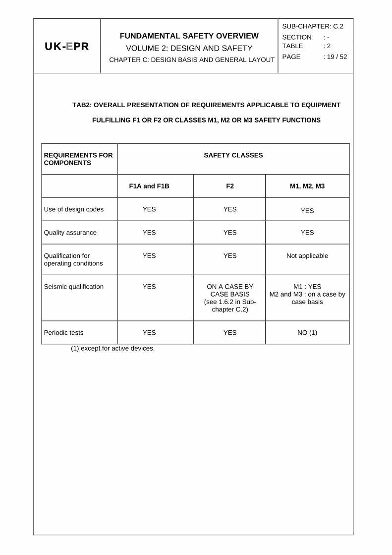
Requirements applicable to equipment fulfilling F1 and F2 safety functions or classified M1, M2 or M3 are summarised in table C.2 TAB 2.
1.10.1. Components fulfilling an F1 function
Requirements applicable to components fulfilling an F1 function are stated below.
- Use of specific common design and construction standards: These common standards indicate the methodologies, rules and criteria to be used for procuring equipment, design, production, construction, inspection and testing of components. The code corresponding to each aspect is defined in 1.7.1 above for mechanical components. For electrical and I&C equipment, the corresponding code is RCC-E.

SUB-CHAPTER: C.2 SECTION : -
PAGE : 14 / 52 UK-EPR
FUNDAMENTAL SAFETY OVERVIEW VOLUME 2: DESIGN AND SAFETY
CHAPTER C: DESIGN BASIS AND GENERAL LAYOUT
- Application of a quality assurance programme: QA programmes must be applied to all stages of component life (design, construction, installation, inspection, testing, operation, modification).
- Qualification for operating conditions (see Chapter C.7): Qualification aims to check that the components of safety-classified systems can fulfil their functions appropriately in the conditions in which they are required to operate (pressure, temperature, humidity, and specific activity corresponding to a LOCA or a severe accident, long term operation, ageing etc.).
- Seismic qualification (see Chapter C.7): This includes the requirement for stability or integrity. Functional capacity or operability requirements must be defined as necessary to meet system functional requirements.
- Periodic testing.
1.10.2. Components fulfilling an F2 function
Requirements applicable to components fulfilling an F2 function are:
- use of a design code which can be an RCC, or another design code or harmonised European standards (with supplements),
- application of a quality assurance programme:
- qualification for the appropriate operating conditions,
- seismic qualification is considered on a case by case basis and applied only when necessary,
- periodic tests.
1.10.3. M1- M2- and M3-classified components
1.10.3.1. General requirements
Requirements applicable to M1- M2- and M3-classified components are stated below.
- Use of specific common design and construction standards (see 1.7 above). These common standards indicate the methodologies, rules and criteria to be used for procuring equipment, design, production, construction, inspection and testing of components.
- Application of a quality assurance programme. QA programmes must be applied to the different stages of component life (design, construction, installation, inspection, testing, operation, modification).
- Seismic qualification (see 1.6 above – on a case by case basis for M2 and M3). This includes the requirement for stability or integrity. Functional capacity or operability requirements must be defined as necessary to meet system functional requirements.
SUB-CHAPTER: C.2 SECTION : -
PAGE : 15 / 52 UK-EPR
FUNDAMENTAL SAFETY OVERVIEW VOLUME 2: DESIGN AND SAFETY
CHAPTER C: DESIGN BASIS AND GENERAL LAYOUT
1.10.3.2. Isolation valves
When an isolation device, whether motorized or not, is used to separate two sections of a system with a different mechanical classifications (or to separate a classified from a non-classified section), the following additional requirements apply:
- If, on account of its functional classification, this device is redundant, the same requirements apply to both of the isolation valves and to the section of the system which may link them.
- The isolation device is classified mechanical at the higher level of the two sections of the system which it separates.
- The device must be qualified for the conditions for which isolation is required.
- In addition, if the device has to manoeuvre to ensure isolation:
- Its functional classification must be at least F2,
- It must be possible to actuate and execute the manoeuvre,
- In the particular case of a classified/non-classified interface, the time taken to operate must be compatible with maintaining contamination of the "downstream" system below mechanical class 3 criteria.
1.11. STRUCTURAL CLASSIFICATION
1.11.1. Classification approach
Buildings have two main functions:
- protecting systems inside the buildings,
- providing a barrier function.
The first function is to protect systems from external hazards, the aim being to prevent consequential internal events.
The second function is linked to the mitigation of the radiological consequences of potential failures inside buildings. Requirements related to this function are described in the Containment sections of the Preliminary Safety Report (see Chapters C.5.0 and F.2.1).
1.11.2. Classification for the system protection function
1.11.2.1. The main functions of buildings in the event of external hazards
Buildings which are required to resist external hazards must meet the following two conditions.
1. an external hazard, considered deterministically, must not prevent any F1 function,
AND
2. an external hazard must not give rise to an unacceptable radiological risk.

SUB-CHAPTER: C.2 SECTION : -
PAGE : 16 / 52 UK-EPR
FUNDAMENTAL SAFETY OVERVIEW VOLUME 2: DESIGN AND SAFETY
CHAPTER C: DESIGN BASIS AND GENERAL LAYOUT
1.11.2.2. C1 classification
Classification related to external hazards thus concerns buildings which house either equipment that ensures F1 functions, or radioactive materials.
Definition of C1 classification
A building is classified C1 if it houses or supports:
- either equipment which fulfils F1 functions,
- or components liable to contain radioactive materials, therefore classified mechanical M1, M2 or M3.
Other buildings are not safety classified: NCB. B
The classification of the various civil structures is given in TAB 7.
1.11.2.3. C1 classification requirements
Based on the requirements and classification set out above, the particular requirements for each of the various structures are set out in Chapter C.5.0 (table C.5.0 TAB 2 in particular).

SUB-CHAPTER: C.2 SECTION : -
PAGE : 17 / 52 UK-EPR
FUNDAMENTAL SAFETY OVERVIEW VOLUME 2: DESIGN AND SAFETY
CHAPTER C: DESIGN BASIS AND GENERAL LAYOUT
2. CLASSIFICATION LIST
All classified systems and related classification requirements are set out in the following tables:
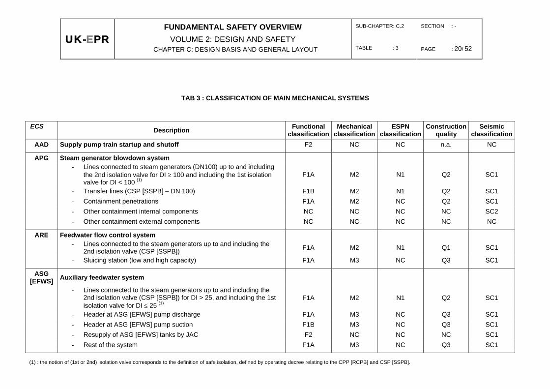
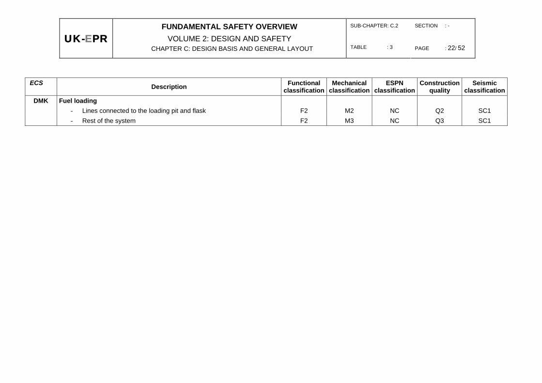
C.2 TAB 3 : Classification of main mechanical systems,
C.2 TAB 4 : Classification of main electrical systems,
C.2 TAB 5 : Classification of main fuel handling and storage equipment,
C.2 TAB 6 : Classification of I&C systems and equipment
C.2 TAB 7 : Classification of civil engineering structures
SUB-CHAPTER: C.2 SECTION : - TABLE : 1 PAGE : 18 / 52
UK-EPR
FUNDAMENTAL SAFETY OVERVIEW VOLUME 2: DESIGN AND SAFETY
CHAPTER C: DESIGN BASIS AND GENERAL LAYOUT
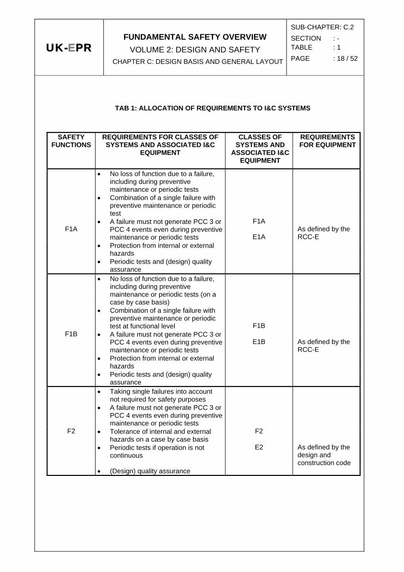
TAB 1: ALLOCATION OF REQUIREMENTS TO I&C SYSTEMS
SAFETY FUNCTIONS
REQUIREMENTS FOR CLASSES OF SYSTEMS AND ASSOCIATED I&C
EQUIPMENT
CLASSES OF SYSTEMS AND
ASSOCIATED I&C EQUIPMENT
REQUIREMENTS FOR EQUIPMENT
• No loss of function due to a failure, including during preventive maintenance or periodic tests
• Combination of a single failure with preventive maintenance or periodic test
F1A
• A failure must not generate PCC 3 or PCC 4 events even during preventive maintenance or periodic tests
F1A
E1A
As defined by the RCC-E
• Protection from internal or external hazards
• Periodic tests and (design) quality assurance
• No loss of function due to a failure, including during preventive maintenance or periodic tests (on a case by case basis)
• Combination of a single failure with preventive maintenance or periodic test at functional level
F1B
F1B • A failure must not generate PCC 3 or PCC 4 events even during preventive maintenance or periodic tests
E1B
As defined by the RCC-E
• Protection from internal or external hazards
• Periodic tests and (design) quality assurance
• Taking single failures into account not required for safety purposes
• A failure must not generate PCC 3 or PCC 4 events even during preventive maintenance or periodic tests
F2 • Tolerance of internal and external hazards on a case by case basis
F2
• Periodic tests if operation is not continuous
E2 As defined by the design and construction code
• (Design) quality assurance
SUB-CHAPTER: C.2 SECTION : - TABLE : 2 PAGE : 19 / 52
UK-EPR
FUNDAMENTAL SAFETY OVERVIEW VOLUME 2: DESIGN AND SAFETY
CHAPTER C: DESIGN BASIS AND GENERAL LAYOUT
TAB2: OVERALL PRESENTATION OF REQUIREMENTS APPLICABLE TO EQUIPMENT
FULFILLING F1 OR F2 OR CLASSES M1, M2 OR M3 SAFETY FUNCTIONS
REQUIREMENTS FOR COMPONENTS
SAFETY CLASSES
F1A and F1B
F2
M1, M2, M3
Use of design codes
YES
YES
YES
Quality assurance
YES
YES
YES
Qualification for operating conditions
YES
YES
Not applicable
Seismic qualification
YES
ON A CASE BY CASE BASIS
(see 1.6.2 in Sub-chapter C.2)
M1 : YES
M2 and M3 : on a case by case basis
Periodic tests
YES
YES
NO (1)
(1) except for active devices.
SUB-CHAPTER: C.2 SECTION : -
UK-EPRFUNDAMENTAL SAFETY OVERVIEW
VOLUME 2: DESIGN AND SAFETY CHAPTER C: DESIGN BASIS AND GENERAL LAYOUT TABLE : 3 PAGE : 20/ 52
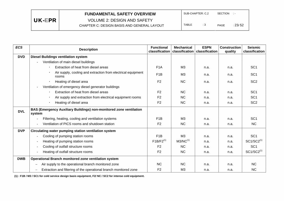
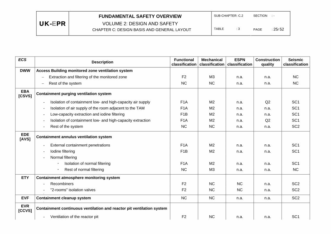
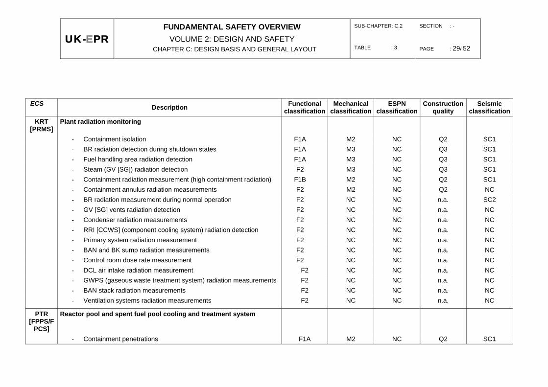
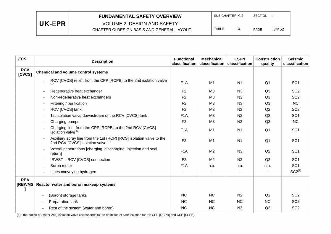
TAB 3 : CLASSIFICATION OF MAIN MECHANICAL SYSTEMS
ECS Description Functional classification
Mechanical classification
ESPN classification
Construction quality
Seismic classification
AAD Supply pump train startup and shutoff F2 NC NC n.a. NC
APG Steam generator blowdown system
- Lines connected to steam generators (DN100) up to and including
the 2nd isolation valve for DI ≥ 100 and including the 1st isolation valve for DI < 100 (1)
F1A M2 N1 Q2 SC1
- Transfer lines (CSP [SSPB] – DN 100) F1B M2 N1 Q2 SC1 - Containment penetrations F1A M2 NC Q2 SC1 - Other containment internal components NC NC NC NC SC2 - Other containment external components NC NC NC NC NC
ARE Feedwater flow control system
- Lines connected to the steam generators up to and including the 2nd isolation valve (CSP [SSPB]) F1A M2 N1 Q1 SC1
- Sluicing station (low and high capacity) F1A M3 NC Q3 SC1
ASG [EFWS] Auxiliary feedwater system
- Lines connected to the steam generators up to and including the
2nd isolation valve (CSP [SSPB]) for DI > 25, and including the 1st isolation valve for DI ≤ 25 (1)
F1A M2 N1 Q2 SC1
- Header at ASG [EFWS] pump discharge F1A M3 NC Q3 SC1 - Header at ASG [EFWS] pump suction F1B M3 NC Q3 SC1 - Resupply of ASG [EFWS] tanks by JAC F2 NC NC NC SC1 - Rest of the system F1A M3 NC Q3 SC1
(1) : the notion of (1st or 2nd) isolation valve corresponds to the definition of safe isolation, defined by operating decree relating to the CPP [RCPB] and CSP [SSPB].

SUB-CHAPTER: C.2 SECTION : -
UK-EPRFUNDAMENTAL SAFETY OVERVIEW
VOLUME 2: DESIGN AND SAFETY CHAPTER C: DESIGN BASIS AND GENERAL LAYOUT TABLE : 3 PAGE : 21/ 52
ECS Description Functional classification
Mechanical classification
ESPN classification
Construction quality
Seismic classification
CFI [CWFS] Circulating water filtration system
- Low-speed rotation of filtering devices (FAC and TF) F1B M3 NC Q3 SC1 - Low-pressure washing of filtering devices (FAC and TF) F1B M3 NC Q3 SC1 - Water level measurements downstream of filtering devices F2 NC NC n.a. SC2
CRF Circulating water condenser cooling system
- Automatic shutoff of CRF pumps in the event of high CFI [CWFS] pressure drop F1B n.a. n.a. n.a. SC1
DCL Air conditioning of the main control room - Ventilation, heating and air conditioning of the control room F1B M3 n.a. n.a. SC1 - Normal filtering F1B M3 n.a. n.a. SC1 - Iodine filtering and isolation dampers F2 NC n.a. n.a. SC1 - Fresh air supply isolation F2 NC n.a. n.a. SC1
DEL Electrical building chilled water system F1B M3 NC Q3 SC1
DER Nuclear island chilled water system - Containment isolation F1A M2 NC Q2 SC1 - Rest of the system NC NC NC NC SC2
DFL Smoke monitoring system F2 NC n.a. n.a. SC2
SUB-CHAPTER: C.2 SECTION : -
UK-EPRFUNDAMENTAL SAFETY OVERVIEW
VOLUME 2: DESIGN AND SAFETY CHAPTER C: DESIGN BASIS AND GENERAL LAYOUT TABLE : 3 PAGE : 22/ 52
ECS Description Functional classification
Mechanical classification
ESPN classification
Construction quality
Seismic classification
DMK Fuel loading - Lines connected to the loading pit and flask F2 M2 NC Q2 SC1 - Rest of the system F2 M3 NC Q3 SC1
SUB-CHAPTER: C.2 SECTION : -
UK-EPRFUNDAMENTAL SAFETY OVERVIEW
VOLUME 2: DESIGN AND SAFETY CHAPTER C: DESIGN BASIS AND GENERAL LAYOUT TABLE : 3 PAGE : 23/ 52
ECS Description Functional
classificationMechanical
classificationESPN
classificationConstruction
quality Seismic
classification DVD Diesel Buildings ventilation system
- Ventilation of main diesel buildings Extraction of heat from diesel areas F1A M3 n.a. n.a. SC1
Air supply, cooling and extraction from electrical equipment rooms F1B M3 n.a. n.a. SC1
Heating of diesel area F2 NC n.a. n.a. SC2 - Ventilation of emergency diesel generator buildings
Extraction of heat from diesel areas F2 NC n.a. n.a. SC1 Air supply and extraction from electrical equipment rooms F2 NC n.a. n.a. SC1 Heating of diesel area F2 NC n.a. n.a. SC2
DVL BAS (Emergency Auxiliary Buildings) non-monitored zone ventilation system
- Filtering, heating, cooling and ventilation systems F1B M3 n.a. n.a. SC1 - Ventilation of PICS rooms and shutdown station F2 NC n.a. n.a. NC
DVP Circulating water pumping station ventilation system - Cooling of pumping station rooms F1B M3 n.a. n.a. SC1 - Heating of pumping station rooms F1B/F2(1) M3/NC(1) n.a. n.a. SC1/SC2(1)
- Cooling of outfall structure rooms F2 NC n.a. n.a. SC1 - Heating of outfall structure rooms F2 NC n.a. n.a. SC1/SC2(1)
DWB Operational Branch monitored zone ventilation system − Air supply to the operational branch monitored zone NC NC n.a. n.a. NC − Extraction and filtering of the operational branch monitored zone F2 M3 n.a. n.a. NC
(1) : F1B / M3 / SC1 for cold service design basis equipment, F2/ NC / SC2 for intense cold equipment.

SUB-CHAPTER: C.2 SECTION : -
UK-EPRFUNDAMENTAL SAFETY OVERVIEW
VOLUME 2: DESIGN AND SAFETY CHAPTER C: DESIGN BASIS AND GENERAL LAYOUT TABLE : 3 PAGE : 24/ 52
ECS Description Functional classification
Mechanical classification
ESPN classification
Construction quality
Seismic classification
DWK Fuel Building (BK) ventilation system - Isolation of air supply/extraction of BK fuel handling area F1A M2 n.a. n.a. SC1 - Isolation of air supply of room adjacent to the emergency air lock F1A M3 n.a. n.a. SC1 - Isolation of extraction of room adjacent to emergency air lock F2 M3 n.a. n.a. SC1 - Isolation of air supply/extraction of the room adjacent to the TAM F1A M3 n.a. n.a. SC1
DWL BAS (Emergency Auxiliary Buildings) monitored zone ventilation system
- Isolation of air supply of the room adjacent to personnel air lock F1A M3 n.a. n.a. SC1 - Isolation of extraction of the room adjacent to personnel air lock F2 M3 n.a. n.a. SC1 - Isolation of normal ventilation of BAS F1B M2 n.a. n.a. SC1 - Extraction in accident condition of BAS and iodine filtering F1B M2 n.a. n.a. SC1 - Isolation of EVU [CHRS] and RIS [SIS] rooms F2 M2 n.a. n.a. NC
DWN BAN (Nuclear Auxiliary Buildings) ventilation system - Isolation dampers for BAN fresh air and outlet F2 M3 n.a. n.a. SC1 - Normal and iodine filtering F2 M3 n.a. n.a. NC - Rest of the system NC NC n.a. n.a. NC
DWQ Liquid Waste Discharge System Building monitored zone ventilation system
− Extraction and filtering of the monitored zone F2 M3 n.a. n.a. NC − Rest of the system NC NC n.a. n.a. NC
SUB-CHAPTER: C.2 SECTION : -
UK-EPRFUNDAMENTAL SAFETY OVERVIEW
VOLUME 2: DESIGN AND SAFETY CHAPTER C: DESIGN BASIS AND GENERAL LAYOUT TABLE : 3 PAGE : 25/ 52
ECS Description Functional
classificationMechanical
classificationESPN
classificationConstruction
quality Seismic
classification DWW Access Building monitored zone ventilation system
− Extraction and filtering of the monitored zone F2 M3 n.a. n.a. NC − Rest of the system NC NC n.a. n.a. NC
EBA [CSVS] Containment purging ventilation system
- Isolation of containment low- and high-capacity air supply F1A M2 n.a. Q2 SC1 - Isolation of air supply of the room adjacent to the TAM F1A M2 n.a. n.a. SC1 - Low-capacity extraction and iodine filtering F1B M2 n.a. n.a. SC1 - Isolation of containment low- and high-capacity extraction F1A M2 n.a. Q2 SC1 - Rest of the system NC NC n.a. n.a. SC2
EDE [AVS] Containment annulus ventilation system
- External containment penetrations F1A M2 n.a. n.a. SC1 - Iodine filtering F1B M2 n.a. n.a. SC1 - Normal filtering Isolation of normal filtering F1A M2 n.a. n.a. SC1 Rest of normal filtering NC M3 n.a. n.a. NC
ETY Containment atmosphere monitoring system - Recombiners F2 NC NC n.a. SC2 - "2-rooms" isolation valves F2 NC NC n.a. SC2 -
EVF Containment cleanup system NC NC n.a. n.a. SC2 -
EVR [CCVS] Containment continuous ventilation and reactor pit ventilation system
- Ventilation of the reactor pit F2 NC n.a. n.a. SC1

SUB-CHAPTER: C.2 SECTION : -
UK-EPRFUNDAMENTAL SAFETY OVERVIEW
VOLUME 2: DESIGN AND SAFETY CHAPTER C: DESIGN BASIS AND GENERAL LAYOUT TABLE : 3 PAGE : 26/ 52
ECS Description Functional classification
Mechanical classification
ESPN classification
Construction quality
Seismic classification
- Rest of the system NC NC n.a. n.a. SC2

SUB-CHAPTER: C.2 SECTION : -
UK-EPRFUNDAMENTAL SAFETY OVERVIEW
VOLUME 2: DESIGN AND SAFETY CHAPTER C: DESIGN BASIS AND GENERAL LAYOUT TABLE : 3 PAGE : 27/ 52
ECS Description Fonctional classification
Mechanical classification
ESPN classification
Construction quality
Seismic classification
EVU [CHRS] Containment heat removal system
- BR internal spray lines F2 NC NC NC SC1 - Corium spreading zone cooling lines (int. BR) F2 NC N2 Q2 SC1 - Sump filter unplugging lines (int. BR) F2 NC N2 Q2 SC1
- Containment penetrations (lines and isolation valves) except for IRWST suction F1A M2 N2 Q2 SC1
- Containment penetrations (lines and isolation valves) for IRWST suction lines F1A M2 NC Q2 SC1
- Containment penetration for the sump filter unplugging line F1A M2 N2 Q2 SC1 - External BR equipment (lines, pumps, heat exchangers) F2 M2 N2 Q2 SC1
- Component cooling systems Trains 1 and 2 (inclusive of EVU [CHRS] / SRU [UCWS] heat exchangers) F2 NC NC NC SC1
JAC Fire protection and classified fire-fighting water distribution systems F2 NC NC NC SC1 -
JDT [FDS] Fire detection system F2 NC NC NC SC1
-
JPI Nuclear island fire protection system - Containment penetration F1A M2 NC Q2 SC1 - Rest of the system F2 NC NC NC SC1
JPV Diesel generator fire protection system F2 NC NC NC SC1
KER [LRMDS] Nuclear island liquid radwaste monitoring and discharge system
- Header and associated lines F2 NC NC NC NC
SUB-CHAPTER: C.2 SECTION : -
UK-EPRFUNDAMENTAL SAFETY OVERVIEW
VOLUME 2: DESIGN AND SAFETY CHAPTER C: DESIGN BASIS AND GENERAL LAYOUT TABLE : 3 PAGE : 28/ 52
SUB-CHAPTER: C.2 SECTION : -
UK-EPRFUNDAMENTAL SAFETY OVERVIEW
VOLUME 2: DESIGN AND SAFETY CHAPTER C: DESIGN BASIS AND GENERAL LAYOUT TABLE : 3 PAGE : 29/ 52
ECS Description Functional classification
Mechanical classification
ESPN classification
Construction quality
Seismic classification
KRT [PRMS]
Plant radiation monitoring
- Containment isolation F1A M2 NC Q2 SC1 - BR radiation detection during shutdown states F1A M3 NC Q3 SC1 - Fuel handling area radiation detection F1A M3 NC Q3 SC1 - Steam (GV [SG]) radiation detection F2 M3 NC Q3 SC1 - Containment radiation measurement (high containment radiation) F1B M2 NC Q2 SC1 - Containment annulus radiation measurements F2 M2 NC Q2 NC - BR radiation measurement during normal operation F2 NC NC n.a. SC2 - GV [SG] vents radiation detection F2 NC NC n.a. NC - Condenser radiation measurements F2 NC NC n.a. NC - RRI [CCWS] (component cooling system) radiation detection F2 NC NC n.a. NC - Primary system radiation measurement F2 NC NC n.a. NC - BAN and BK sump radiation measurements F2 NC NC n.a. NC - Control room dose rate measurement F2 NC NC n.a. NC - DCL air intake radiation measurement F2 NC NC n.a. NC - GWPS (gaseous waste treatment system) radiation measurements F2 NC NC n.a. NC - BAN stack radiation measurements F2 NC NC n.a. NC - Ventilation systems radiation measurements F2 NC NC n.a. NC
PTR [FPPS/F
PCS]
Reactor pool and spent fuel pool cooling and treatment system
- Containment penetrations F1A M2 NC Q2 SC1

SUB-CHAPTER: C.2 SECTION : -
UK-EPRFUNDAMENTAL SAFETY OVERVIEW
VOLUME 2: DESIGN AND SAFETY CHAPTER C: DESIGN BASIS AND GENERAL LAYOUT TABLE : 3 PAGE : 30/ 52
ECS Description Functional classification
Mechanical classification
ESPN classification
Construction quality
Seismic classification
PTR [FPPS/FP
CS]
Reactor pool and spent fuel pool cooling and treatment system (cont.)
- BK spent fuel pool cooling Main trains upstream of heat exchangers F1B M2 NC Q2 SC1
Heat exchangers of main cooling trains and lines downstream F1B M2 N3 Q2 SC1
3rd train upstream of heat exchangers F2 M2 NC Q2 SC1
PTR [FPPS/FPCS] 3rd train heat exchanger and lines downstream F2 M2 N3 Q2 SC1
- Skimming, purification and transfer of reactor and BK spent fuel pool water
Compartment drainage lines up to and including the 2nd isolation valve F1A M2 NC Q2 SC1
Rest of the system NC M3 NC Q3 SC2
RBS [ABS] Safety boration
- CPP [RCPB] branch pipes up to and including the 1st isolation valve on the SE RBS [RBS] (1) F1A M1 N1 Q1 SC1
- Containment penetrations F1A M2 NC Q2 SC1 - Rest of the system F1A M3 NC Q3 SC1
RCP [RCS] Reactor coolant system
- Reactor ve ssel Vessel body and head F1A M1 N1 Q1 SC1 Vessel support ring F1A n.a. n.a. Supp Q1 SC1

SUB-CHAPTER: C.2 SECTION : -
UK-EPRFUNDAMENTAL SAFETY OVERVIEW
VOLUME 2: DESIGN AND SAFETY CHAPTER C: DESIGN BASIS AND GENERAL LAYOUT TABLE : 3 PAGE : 31/ 52
ECS Description Functional classification
Mechanical classification
ESPN classification
Construction quality
Seismic classification
Vessel sealwater leakoff line (DI<25) up to and including the 1st isolation valve (1) F2 M3 N3 Q3 SC2
- Vessel vent lines up to and including 1st isolation valve (DI<25) (1) F1A M1 N1 Q1 SC1 - Vessel vent line downstream of the 1st isolation valve (DI<25) (1) F2 M3 NC Q3 SC2
(1) : the notion of (1st or 2nd) isolation valve corresponds to the definition of safe isolation, relating to the CPP [RCPB] and CSP [SSPB].

SUB-CHAPTER: C.2 SECTION : -
UK-EPRFUNDAMENTAL SAFETY OVERVIEW
VOLUME 2: DESIGN AND SAFETY CHAPTER C: DESIGN BASIS AND GENERAL LAYOUT TABLE : 3 PAGE : 32/ 52
ECS Description Functional
classificationMechanical
classificationESPN
classificationConstruction
quality Seismic
classification RCP
[RCS] Reactor coolant system (cont.)
- Vessel internal Components considered as core supports n.a. n.a. n.a. CS SC1 Other internal structures n.a. n.a. n.a. IS SC1 - Control Rod Drive Mechanisms Rod monitoring mechanisms F1A M1 n.a. Q1 SC1 Pressure boundary F1A M1 N1 Q1 SC1 Anti-seismic supports n.a. n.a. n.a. Q1 SC1 Other equipment n.a. NC n.a. n.a. SC2 - Primary coolant loops F1A M1 N1 Q1 SC1 - Steam generators Tube assembly / secondary assembly F1A M1/M2 N1 Q1 SC1
Supporting elements directly welded onto the pressure boundary n.a. n.a. n.a. Q1 SC1
Secondary sampling lines up to the 1st isolation valve (since DN ≤ 100) (1) F1A M2 N1 Q2 SC1
- Pressuriser Pressuriser, pressure relief valves and surge line F1A M1 N1 Q1 SC1 Normal spray lines and valves F2 M1 N1 Q1 SC1
Auxiliary spray lines and valves up to the 2nd isolation valve (1) F2 M1 N1 Q1 SC1
Severe accident depressurization line up to the 2nd isolation valve (1) F2 M1 N1 Q1 SC1
(1) : the notion of (1st or 2nd) isolation valve corresponds to the definition of safe isolation, defined by operating decree relating to the CPP [RCPB] and CSP [SSPB].

SUB-CHAPTER: C.2 SECTION : -
UK-EPRFUNDAMENTAL SAFETY OVERVIEW
VOLUME 2: DESIGN AND SAFETY CHAPTER C: DESIGN BASIS AND GENERAL LAYOUT TABLE : 3 PAGE : 33/ 52
ECS Description Functional
classificationMechanical
classificationESPN
classificationConstruction
quality Seismic
classification RCP
[RCS] Reactor coolant system (cont.)
Pressuriser vent lines up to and including the 2nd isolation valve (1) F1B M1 N1 Q1 SC1
REN [NSS] (nuclear sampling system) sampling line up to the 1st isolation valve (1) F1B M1 N1 Q1 SC1
Heater sleeves, heater well flanges NC M1 N1 Q1 SC1 - Reactor coolant pumps Diffuser and cavity gap seal no. 1 NC M1 N1 Q1 SC1 Cavity gap seals nos. 2 & 3 F2 M2 NC Q2 SC1 DEA [SSSS] F1B M2 NC Q2 SC1 DEA [SSSS] nitrogen supply lines F1B M3 NC Q3 SC1 Injection lines at no. 3 seals from check valve to pump F1B M2 NC Q2 SC1 Injection line at no. 1 seals F1B M1 N1 Q1 SC1
Leakoff lines for seals nos. 1, 2 & 3 up to and including the 1st isolation valve (1) F1A M2 NC Q2 SC1
Leakoff lines for seals nos. 1, 2 & 3 downstream of 1st isolation valve (1) F2 M3 NC Q3 SC1
Thermal barrier supply lines (except for GMPP [RCP]) F1B M3 NC Q3 SC1 - Pressuriser relief tank (tank, lines, bursting disks) F2 M3 N3 Q3 SC1
(1) : the notion of (1st or 2nd) isolation valve corresponds to the definition of safe isolation, defined by operating decree relating to the CPP [RCPB] and CSP [SSPB].
SUB-CHAPTER: C.2 SECTION : -
UK-EPRFUNDAMENTAL SAFETY OVERVIEW
VOLUME 2: DESIGN AND SAFETY CHAPTER C: DESIGN BASIS AND GENERAL LAYOUT TABLE : 3 PAGE : 34/ 52
ECS Description Functional classification
Mechanical classification
ESPN classification
Construction quality
Seismic classification
RCV [CVCS] Chemical and volume control systems
- RCV [CVCS] relief, from the CPP [RCPB] to the 2nd isolation valve (1) F1A M1 N1 Q1 SC1
- Regenerative heat exchanger F2 M3 N3 Q3 SC2 - Non-regenerative heat exchangers F2 M3 N3 Q3 SC2 - Filtering / purification F2 M3 N3 Q3 NC - RCV [CVCS] tank F2 M3 N2 Q2 SC2 - 1st isolation valve downstream of the RCV [CVCS] tank F1A M3 N2 Q2 SC1 - Charging pumps F2 M3 N3 Q3 NC
- Charging line, from the CPP [RCPB] to the 2nd RCV [CVCS] isolation valve (1) F1A M1 N1 Q1 SC1
- Auxiliary spray line from the 1st (RCP) [RCS] isolation valve to the 2nd RCV [CVCS] isolation valve (1) F2 M1 N1 Q1 SC1
- Vessel penetrations [charging, discharging, injection and seal return] F1A M2 N3 Q2 SC1
- IRWST – RCV [CVCS] connection F2 M2 N2 Q2 SC1 - Boron meter F1A n.a. n.a. n.a. SC1 - Lines conveying hydrogen - - - - SC2(2)
REA [RBWMS
] Reactor water and boron makeup systems
− (Boron) storage tanks NC NC N2 Q2 SC2 − Preparation tank NC NC NC NC SC2 − Rest of the system (water and boron) NC NC N3 Q3 SC2
(1) : the notion of (1st or 2nd) isolation valve corresponds to the definition of safe isolation for the CPP [RCPB] and CSP [SSPB].

SUB-CHAPTER: C.2 SECTION : -
UK-EPRFUNDAMENTAL SAFETY OVERVIEW
VOLUME 2: DESIGN AND SAFETY CHAPTER C: DESIGN BASIS AND GENERAL LAYOUT TABLE : 3 PAGE : 35/ 52
(2) : if hazard risk to equipment or SC1 function

SUB-CHAPTER: C.2 SECTION : -
UK-EPRFUNDAMENTAL SAFETY OVERVIEW
VOLUME 2: DESIGN AND SAFETY CHAPTER C: DESIGN BASIS AND GENERAL LAYOUT TABLE : 3 PAGE : 36/ 52
ECS Description Functional classification
Mechanical classification
ESPN classification
Construction quality
Seismic classification
REN [NSS] Primary sampling
- RCP [RCS] (reactor coolant system) sampling
Lines connected to the RCP [RCS] up to and including the 1st isolation valve (1) F1B M1 N1 Q1 SC1
Containment penetrations F1A M2 N3 Q2 SC1 REN [NSS] heat exchangers F2 M3 NC Q3 SC2 - RIS [SIS] (safety injection system) sampling Lines connected to RIS [SIS] trains F2 M3 N3 Q3 NC RIS [SIS] accumulator sampling containment penetrations F1A M2 NC Q2 SC1 - Lines conveying hydrogen - - - - SC2 (2)
- Rest of the system F2 M3 NC Q3 NC
RES Secondary sampling - Lines connected to the CSP [SSPB] (containment penetrations) F1A M2 NC Q2 SC1 - GV [SG] sampling F2 M3 NC Q3 SC2/NC(3)
- Rest of the system F2 NC NC NC NC
RGL [CRDM] Rod control system F1A n.a. n.a. n.a. SC1
RIC In-core instrumentation system
- Fixed measurements of local flux (SPND self-powered neutron detectors) F1A M3 NC Q3 SC1
- Core outlet temperature F1B M3 NC Q3 SC1 - Vessel level measurement F1B M3 NC Q3 SC1
(1) : the notion of (1st or 2nd) isolation valve corresponds to the definition of safe isolation for the CPP [RCPB] and CSP [SSPB]. (2) : if hazard risk to equipment or SC1 function (3) : SC2 for BK & BR lines, NC for the rest.

SUB-CHAPTER: C.2 SECTION : -
UK-EPRFUNDAMENTAL SAFETY OVERVIEW
VOLUME 2: DESIGN AND SAFETY CHAPTER C: DESIGN BASIS AND GENERAL LAYOUT TABLE : 3 PAGE : 37/ 52
ECS Description Functional
classificationMechanical
classificationESPN
classificationConstruction
quality Seismic
classification RIS [SIS] Safety injection system / residual heat removal
- ISMP [MHSI]-ISBP [LHSI] common injection lines and connected lines, from the CPP [RCPB] up to the 2nd isolation valve (1) F1A M1 N1 Q1 SC1
- BF [CL] injection lines and connected lines, from the CPP [RCPB] up to and including the 2nd isolation valve (1) F1A M1 N1 Q1 SC1
- IRWST suction lines F1A M2 N2 Q2 SC1 - IRWST suction containment penetrations F1A M2 NC Q2 SC1 - Residual heat removal lines F1B M2 N2 Q2 SC1 - ISMP [MHSI]/ISBP [LHSI] low-flow lines F1A M2 N2 Q2 SC1 - ISBP [LHSI] heat exchangers F1A M2 N2 Q2 SC1 - RIS [SIS] accumulators and connected lines F1A M3 NC Q3 SC1 - Lines downstream of accumulator valves NC NC NC n.a. SC2
RPE Nuclear island vent and drain system Containment penetrations F1A M2 N3 Q2 SC1 Collection of BR primary waste (storage tanks & connected lines) F2 M3 N3 Q3 SC2 Collection of BAS primary waste (storage tanks & connected lines) F2 M3 N3 Q3 SC2 Collection of BAN primary waste (storage tanks & connected lines) F2 M3 N3 Q3 NC BR process vents and drains (storage tanks & connected lines) F2 M3 NC Q3 SC2 BAS/BK process drains (storage tanks & connected lines) F2 M3 NC Q3 SC2 BAN process drains (storage tanks & connected lines) F2 M3 N3 Q3 NC BAN chemical drains (storage tanks & connected lines) F2 M3 NC Q3 NC Floor 1 drains (storage tanks & connected lines) F2 M3 NC Q3 SC2 Floor 2 drains (storage tanks & connected lines) F2 M3 NC Q3 SC2 Floor 3 drains (storage tanks & connected lines) F2 M3 NC Q3 SC2 Collection of valve discharge in the BAN (storage tanks & connected lines) F2 M3 N3 Q3 NC

SUB-CHAPTER: C.2 SECTION : -
UK-EPRFUNDAMENTAL SAFETY OVERVIEW
VOLUME 2: DESIGN AND SAFETY CHAPTER C: DESIGN BASIS AND GENERAL LAYOUT TABLE : 3 PAGE : 38/ 52
ECS Description Functional classification
Mechanical classification
ESPN classification
Construction quality
Seismic classification
Re-injection of waste into the BR F2 M3 NC Q3 NC

SUB-CHAPTER: C.2 SECTION : -
UK-EPRFUNDAMENTAL SAFETY OVERVIEW
VOLUME 2: DESIGN AND SAFETY CHAPTER C: DESIGN BASIS AND GENERAL LAYOUT TABLE : 3 PAGE : 39/ 52
ECS Description Functional classification
Mechanical classification
ESPN classification
Construction quality
Seismic classification
RPN Nuclear instrumentation system F1A n.a. n.a. n.a. SC1
RRI [CCWS] Component cooling system
- F1 utilization equipment on 1/2/3/4 trains: associated lines and valves F1A M3 NC Q3 SC1
To ISBP [LHSI] heat exchangers F1A M3 NC Q3 SC1 To ISMP [MHSI]/ISBP [LHSI] pump motor coolers F1A M3 NC Q3 SC1 To ISMP [MHSI] pump sealing fluid coolers F1A M3 NC Q3 SC1 DEL cooling F1B M3 NC Q3 SC1 - BK : 1 and 2 commons
To PTR [FPPS/FPCS] heat exchangers: associated lines and valves F1B M3 NC Q3 SC1
RCV [CVCS] pump cooling F2 M3 NC Q3 SC2
To all other utilization equipment: associated lines and valves NC M3 NC Q3 SC2
- BR : RCP [RCS] utilization equipment To thermal barriers: associated lines and valves F1B M3 NC Q3 SC1 To GMPP [RCP] motor coolers: associated lines and valves NC M3 NC Q3 SC2 Containment penetrations: associated lines and valves F1A M2 NC Q2 SC1
To RCV [CVCS] HP heat exchangers: associated lines and valves NC M3 NC Q3 SC2
To other utilization equipment: associated lines and valves NC M3 NC Q3 SC2 - BAN utilization equipment: associated lines and valves NC M3 NC Q3 NC
SAT Service compressed air distribution system - Containment penetration F1A M2 NC Q2 SC1
SUB-CHAPTER: C.2 SECTION : -
UK-EPRFUNDAMENTAL SAFETY OVERVIEW
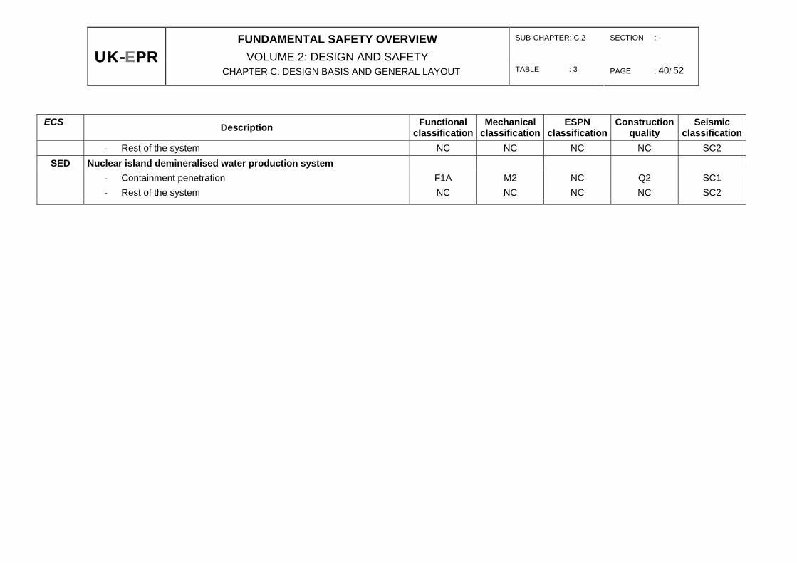
VOLUME 2: DESIGN AND SAFETY CHAPTER C: DESIGN BASIS AND GENERAL LAYOUT TABLE : 3 PAGE : 40/ 52
ECS Description Functional classification
Mechanical classification
ESPN classification
Construction quality
Seismic classification
- Rest of the system NC NC NC NC SC2 SED Nuclear island demineralised water production system
- Containment penetration F1A M2 NC Q2 SC1 - Rest of the system NC NC NC NC SC2
SUB-CHAPTER: C.2 SECTION : -
UK-EPRFUNDAMENTAL SAFETY OVERVIEW
VOLUME 2: DESIGN AND SAFETY CHAPTER C: DESIGN BASIS AND GENERAL LAYOUT TABLE : 3 PAGE : 41/ 52
ECS Description Functional classification
Mechanical classification
ESPN classification
Construction quality
Seismic classification
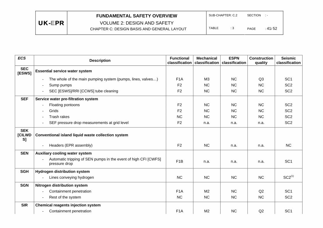
SEC [ESWS] Essential service water system
- The whole of the main pumping system (pumps, lines, valves…) F1A M3 NC Q3 SC1 - Sump pumps F2 NC NC NC SC2 - SEC [ESWS]/RRI [CCWS] tube cleaning F2 NC NC NC SC2
SEF Service water pre-filtration system - Floating pontoons F2 NC NC NC SC2 - Grids F2 NC NC NC SC2 - Trash rakes NC NC NC NC SC2 - SEF pressure drop measurements at grid level F2 n.a. n.a. n.a. SC2
SEK [CILWD
S] Conventional island liquid waste collection system
- Headers (EPR assembly) F2 NC n.a. n.a. NC
SEN Auxiliary cooling water system
- Automatic tripping of SEN pumps in the event of high CFI [CWFS] pressure drop F1B n.a. n.a. n.a. SC1
SGH Hydrogen distribution system - Lines conveying hydrogen NC NC NC NC SC2(1)
SGN Nitrogen distribution system - Containment penetration F1A M2 NC Q2 SC1 - Rest of the system NC NC NC NC SC2
SIR Chemical reagents injection system - Containment penetration F1A M2 NC Q2 SC1

SUB-CHAPTER: C.2 SECTION : -
UK-EPRFUNDAMENTAL SAFETY OVERVIEW
VOLUME 2: DESIGN AND SAFETY CHAPTER C: DESIGN BASIS AND GENERAL LAYOUT TABLE : 3 PAGE : 42/ 52
ECS Description Functional classification
Mechanical classification
ESPN classification
Construction quality
Seismic classification
- Rest of the system NC NC NC NC SC2
(1) : if hazard risk to equipment or SC1 function

SUB-CHAPTER: C.2 SECTION : -
UK-EPRFUNDAMENTAL SAFETY OVERVIEW
VOLUME 2: DESIGN AND SAFETY CHAPTER C: DESIGN BASIS AND GENERAL LAYOUT TABLE : 3 PAGE : 43/ 52
ECS Description Functional
classificationMechanical
classificationESPN
classificationConstruction
quality Seismic
classification SNL GV [SG] lancing
- Containment penetration F1A M2 NC Q2 SC1 - Rest of the system NC NC NC NC SC2
SRU [UCWS] Ultimate cooling system
- Cooling system of train 1 SRU [UCWS] assembly (pumps, valves) F2 NC NC NC SC1 - Cooling system of train 2 SRU [UCWS] assembly (pumps, valves) F2 NC NC NC SC1 - Diversity via suction in the outfall structure F2 NC NC NC SC2
TEG [GWPS] Gaseous waste treatment system
- Containment penetrations F1A M2 N3 Q2 SC1 - Lines conveying hydrogen - - - - SC2(1)
- Rest of the system F2 M3 N3 Q3 NC
TEP [CSTS] Boron recycle system
- TEP [CSTS] storage F2 M3 N2 Q2 NC - Boric acid column and connected lines F2 M3 N3 Q3 NC - Treatment of distillates / concentrates and low-capacity degasser F2 M3 N3/NC Q3 NC - High-capacity degasser F2 M3 N3 Q3 NC
TER [ExLWD
S] Liquid waste discharge system
- Header F2 NC n.a. n.a. NC

SUB-CHAPTER: C.2 SECTION : -
UK-EPRFUNDAMENTAL SAFETY OVERVIEW
VOLUME 2: DESIGN AND SAFETY CHAPTER C: DESIGN BASIS AND GENERAL LAYOUT TABLE : 3 PAGE : 44/ 52
ECS Description Functional classification
Mechanical classification
ESPN classification
Construction quality
Seismic classification
TES [SWTS] Solid waste treatment system F2 M3 NC n.a. NC
TEU [LWPS] Liquid waste treatment system F2 M3 NC n.a. NC
(1) : if hazard risk to equipment or SC1 function

SUB-CHAPTER: C.2 SECTION : -
UK-EPRFUNDAMENTAL SAFETY OVERVIEW
VOLUME 2: DESIGN AND SAFETY CHAPTER C: DESIGN BASIS AND GENERAL LAYOUT TABLE : 3 PAGE : 45/ 52
ECS Description Functional
classificationMechanical
classificationESPN
classificationConstruction
quality Seismic
classification VDA Vent to atmosphere (Steam dump)
- Vent to atmosphere lines, isolation valves and VDA [MSSS] control valves F1A M2 N1 Q1 SC1
- Vent lines downstream of control valves and VVP [MSSS] valves F1A M3 NC Q3 SC1
VVP [MSSS] Main steam system
- Main steam lines up to main steam isolation valves VIV [MSIV] F1A M2 N1 Q1 SC1 - Main lines downstream of VIV [MSIV] up to fixed points F1A M2 NC Q1 SC1
- Conditioning lines (VIV bypass) up to and including the 2nd isolation valve (1) F1A M2 N1 Q2 SC1
- Conditioning lines (VIV bypass) downstream of the 2nd isolation valve F1A M2 NC Q2 SC1
- Blowdown lines up to and including the 1st isolation valve (1) F1A M2 N1 Q2 SC1
- Blowdown lines of the 1st isolation valve up to and including the 2nd isolation valve (1) F1A M2 NC Q2 SC1
- VIV pilot valves F1A M3 NC Q3 SC1 - Pressure relief valves F1A M2 N1 Q1 SC1
(1) : the notion of (1st or 2nd) isolation valve corresponds to the definition of safe isolation, defined by operating decree relating to the CPP [RCPB] and CSP [SSPB].

SUB-CHAPTER: C.2 SECTION : -
UK-EPRFUNDAMENTAL SAFETY OVERVIEW
VOLUME 2: DESIGN AND SAFETY CHAPTER C: DESIGN BASIS AND GENERAL LAYOUT TABLE : 4 PAGE : 46/ 52
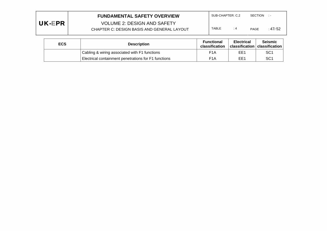
TAB 4: CLASSIFICATION OF MAIN ELECTRICAL SYSTEMS
ECS Description Functional classification
Electrical classification
Seismic classification
LH. 10 kV emergency power system F1A EE1 SC1 LJA/B/C/D/F/I 690 V emergency power system F1A EE1 SC1
LJU/X/Z 690 V emergency power system F2 EE2 SC1 LJP/S 690 V emergency diesel generator sets (SBO diesel sets) F2 EE2 SC1
LLA/B/C/D/F/G/H/I 400 V AC emergency power system F1A EE1 SC1 LLP/Q/R/S 400 V AC emergency power system F1B EE1 SC1 LHP/Q/R/S 10 kV main emergency diesel generator sets F1A EE1 SC1
LO. 230 / 400 V AC regulated power system F1A EE1 SC1 LVA/B/C/D/F/G/H/I 400 V AC uninterruptible power supply and associated distribution F1A EE1 SC1
LVP/S Severe accident battery backed supply and associated distribution
F2 EE2 SC2
LA. BTD 220 V DC power system F1A EE1 SC1
LA. Power supply to control rod latches, AAR (reactor trip) circuit breakers
F1A EE1 SC1
LG. 10 kV nuclear island power system F2 EE2 SC2
LG. 10 kV nuclear island power systems, GMPP [RCP] circuit breakers
F1A EE1 SC1
LI. 690 V AC nuclear island power system F2 EE2 SC2 LK.1 400 V nuclear island power system F2 EE2 SC2 LK.2 Normal power supply to pressuriser heaters F2 EE2 SC2 LL.2 Emergency power supply to pressuriser heaters F2 EE2 SC2 LK.2 Power supply to on-off pressuriser heaters F2 EE2 SC2 LTR Grounding system and lightning protection F2 EE2 SC2 DN Normal lighting NC NC SC2 DS Emergency lighting F2 EE2 SC1
KKK Site and building access control system NC NC SC2 JDT [FDS] Fire detection systems and alarms F2 EE2 SC1
SUB-CHAPTER: C.2 SECTION : -
UK-EPRFUNDAMENTAL SAFETY OVERVIEW
VOLUME 2: DESIGN AND SAFETY CHAPTER C: DESIGN BASIS AND GENERAL LAYOUT TABLE : 4 PAGE : 47/ 52
ECS Description Functional classification
Electrical classification
Seismic classification
Cabling & wiring associated with F1 functions F1A EE1 SC1 Electrical containment penetrations for F1 functions F1A EE1 SC1

SUB-CHAPTER: C.2 SECTION : - TABLE : 5 PAGE : 48 / 52
UK-EPR
FUNDAMENTAL SAFETY OVERVIEW VOLUME 2: DESIGN AND SAFETY
CHAPTER C: DESIGN BASIS AND GENERAL LAYOUT
TAB 5: CLASSIFICATION OF MAIN FUEL HANDLING AND STORAGE SYSTEMS
Equipment classification Description
KTA CST Seismic
classification Quality
assurance
Fuel manipulator crane Fuel manipulator
crane requirements
Level 2 SC2 Yes
Fuel transfer device Additional requirements Level 2 SC1 Yes
- Isolation - Transfer tube
F1A M2
F1A M2
SC1 SC1
Yes Yes
Hookstick crane Fuel manipulator
crane requirements
Level 2 SC2 Yes
Fuel elevator Additional requirements Level 2 SC2 Yes
Auxiliary hoist Additional requirements Level 2 SC2 Yes
Irradiated fuel flask manipulator crane (DMK) (1)
(Specific parts of the irradiated fuel flask manipulator crane, including the structure, travel and direction drives, travel guides, upper trunnion clamping system and anti-seismic devices)
Additional requirements Level 2 SC1 Yes
Cover hoist at loading pit bottom Additional requirements Level 2 SC2 Yes
Biological plug handling station Additional requirements Level 2 SC2 Yes
Alignment device under the penetration Additional requirements Level 2 SC2 Yes
Polar crane main hoist Increased requirements Level 1 SC2 Yes
Polar crane secondary hoist Increased requirements Level 1 SC2 Yes
Polar crane auxiliary hoist Increased requirements Level 1 SC2 Yes
Spent fuel manual handling tool Additional requirements Level 2 SC2 Yes
Reactor Building walkway Non classified Non classified SC2 Yes Spent fuel examination facility Non classified Non classified SC2 Yes Fresh fuel dry storage rack Non classified Non classified SC1 Yes Fuel underwater storage rack Non classified Non classified SC1 Yes
- Structure Q2 level component
support
Q2 level component
support
SC1 Yes
The reference chosen is KTA 3902 or CST 60.C.007.03 (1) : The DMK fluid system plant is dealt with in table 1.
SUB-CHAPTER: C.2 SECTION : - TABLE : 6 PAGE : 49 / 52
UK-EPR
FUNDAMENTAL SAFETY OVERVIEW VOLUME 2: DESIGN AND SAFETY
CHAPTER C: DESIGN BASIS AND GENERAL LAYOUT
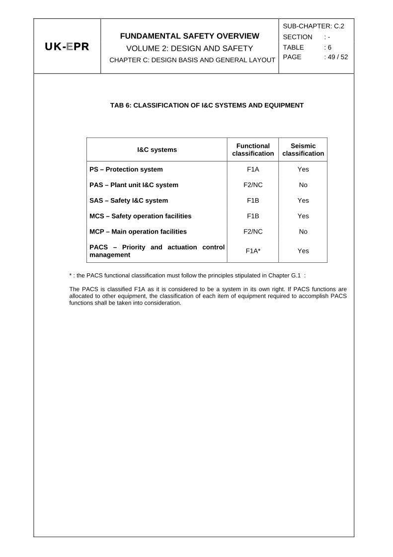
TAB 6: CLASSIFICATION OF I&C SYSTEMS AND EQUIPMENT
I&C systems Functional classification
Seismic classification
PS – Protection system F1A Yes
PAS – Plant unit I&C system F2/NC No
SAS – Safety I&C system F1B Yes
MCS – Safety operation facilities F1B Yes
MCP – Main operation facilities F2/NC No
PACS – Priority and actuation control management F1A* Yes
* : the PACS functional classification must follow the principles stipulated in Chapter G.1 : The PACS is classified F1A as it is considered to be a system in its own right. If PACS functions are allocated to other equipment, the classification of each item of equipment required to accomplish PACS functions shall be taken into consideration.

SUB-CHAPTER: C.2 SECTION :-
UK-EPRFUNDAMENTAL SAFETY OVERVIEW
VOLUME 2: DESIGN AND SAFETY CHAPTER C: DESIGN BASIS AND GENERAL LAYOUT TABLE : 7 PAGE : 50 / 52
TAB 7 : CLASSIFICATION OF CIVIL ENGINEERING STRUCTURES
Description System protection
Seismic classification
Protection from aircraft crashes
Protection from external
explosion
Reactor building (BR) C1 Yes Yes
Internal containment and dome (Containment barrier) - Inclusive of structures, i.e. SC1
Prestressing (including anchoring and anchoring concrete)
Containment penetration sleeves, polar crane brackets, equipment hatch material
Others, including polar crane brackets - Other structures and components SC2
Internal structures and external containment, raft foundation and containment dome
- Inclusive of structures, i.e. SC1 IRWST metal liner Reactor cavities metal liner Metal parts embedded in the concrete
- Protection shields SC2 - Other structures and components SC2
Nuclear auxiliary buildings (BAN) C1 No Yes (1)
- Structures SC1 - Other structures and components NC
(1) – Protecting the BAN must take into account radioactive discharge risks.

SUB-CHAPTER: C.2 SECTION : -
UK-EPRFUNDAMENTAL SAFETY OVERVIEW
VOLUME 2: DESIGN AND SAFETY TABLE : 7 CHAPTER C: DESIGN BASIS AND GENERAL LAYOUT PAGE : 51 / 52
Description System protection
Seismic classification
Protection from aircraft crashes
Protection from external
explosion
Emergency auxiliary buildings & electrical buildings C1 Yes by physical
separation or aircraft shell
Yes
- Structures, i.e. ASG [EFWS] tank liners, metal parts embedded in the concrete SC1
- Other structures and components SC2
Fuel buildings (BK) C1 Yes Yes
- Structures i.e. metal liners (spent fuel pool, transfer compartment), metal parts embedded in the concrete SC1
- Other structures and components SC2
Diesel generator buildings C1 No (2) Yes
- Structures SC1 - Other structures and components SC2
Pumping station C1 Yes by physical
separation or aircraft shell
Yes
- Structures, i.e. water intake structure from the pumping station and pipes connected to class 1 seismic buildings SC1
- Other structures and components SC2
(2) – Protecting diesel generator buildings and the pumping station from aircraft crashes is ensured by physical separation

SUB-CHAPTER: C.2 SECTION : -
UK-EPRFUNDAMENTAL SAFETY OVERVIEW
VOLUME 2: DESIGN AND SAFETY CHAPTER C: DESIGN BASIS AND GENERAL LAYOUT TABLE : 7 PAGE : 52 / 52
Description System protection
Seismic classification
Protection from aircraft crashes
Protection from external
explosion
Waste treatment building C1 SC1 No Yes
BAN stack NC SC2 No Yes
Turbine hall NC SC2 No No
BAN/BTE gallery C1 SC1 Non No
SEC [ESWS] galleries C1 SC1 No (2) No
BL access tower NC SC2 No Yes (2) –Protecting diesel generator buildings and the pumping station from aircraft crashes is ensured by physical separation


![SUB CHAPTER J.4 OTHER FEATURES OF STEAM AND …epr-reactor.co.uk/ssmod/liblocal/docs/V3/Volume 2 - Design and... · TURBINE BYPASS SYSTEM (GCT) [MSB] 3.1. ROLE AND DESCRIPTION The](https://img.dokumen.tips/doc/110x75/5afa4fae7f8b9aac248fa658/sub-chapter-j4-other-features-of-steam-and-epr-2-design-andturbine-bypass.jpg)


![PCSR – Sub-chapter 7.7 – I&C tools, development process ...epr-reactor.co.uk/ssmod/liblocal/docs/PCSR/Chapter 7...RRC-B SASand Process Information and Control System (MCP [PICS])](https://img.dokumen.tips/doc/110x75/6120260e89bb271b4759af47/pcsr-a-sub-chapter-77-a-ic-tools-development-process-epr-7-rrc-b.jpg)


![SUB CHAPTER G.4 F2 CLASSIFIED AND NON CLASSIFIED ...epr-reactor.co.uk/ssmod/liblocal/docs/V3/Volume 2... · The MCP[PICS] performs F2 and NC operating and monitoring functions. According](https://img.dokumen.tips/doc/110x75/5fa719ad5d46ab09e36056b3/sub-chapter-g4-f2-classified-and-non-classified-epr-2-the-mcppics-performs.jpg)


