Embed Size (px)
Citation preview
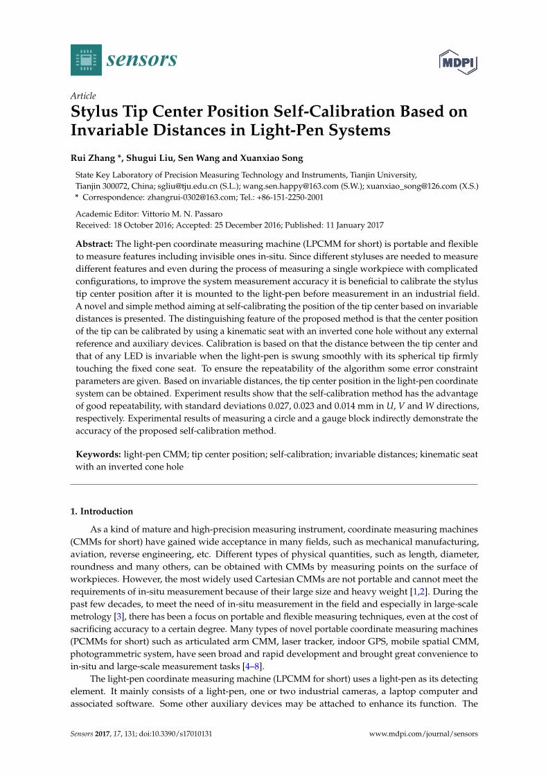
sensors
Article
Stylus Tip Center Position Self-Calibration Based onInvariable Distances in Light-Pen Systems
Rui Zhang *, Shugui Liu, Sen Wang and Xuanxiao Song
State Key Laboratory of Precision Measuring Technology and Instruments, Tianjin University,Tianjin 300072, China; [email protected] (S.L.); [email protected] (S.W.); [email protected] (X.S.)* Correspondence: [email protected]; Tel.: +86-151-2250-2001
Academic Editor: Vittorio M. N. PassaroReceived: 18 October 2016; Accepted: 25 December 2016; Published: 11 January 2017
Abstract: The light-pen coordinate measuring machine (LPCMM for short) is portable and flexibleto measure features including invisible ones in-situ. Since different styluses are needed to measuredifferent features and even during the process of measuring a single workpiece with complicatedconfigurations, to improve the system measurement accuracy it is beneficial to calibrate the stylustip center position after it is mounted to the light-pen before measurement in an industrial field.A novel and simple method aiming at self-calibrating the position of the tip center based on invariabledistances is presented. The distinguishing feature of the proposed method is that the center positionof the tip can be calibrated by using a kinematic seat with an inverted cone hole without any externalreference and auxiliary devices. Calibration is based on that the distance between the tip center andthat of any LED is invariable when the light-pen is swung smoothly with its spherical tip firmlytouching the fixed cone seat. To ensure the repeatability of the algorithm some error constraintparameters are given. Based on invariable distances, the tip center position in the light-pen coordinatesystem can be obtained. Experiment results show that the self-calibration method has the advantageof good repeatability, with standard deviations 0.027, 0.023 and 0.014 mm in U, V and W directions,respectively. Experimental results of measuring a circle and a gauge block indirectly demonstrate theaccuracy of the proposed self-calibration method.
Keywords: light-pen CMM; tip center position; self-calibration; invariable distances; kinematic seatwith an inverted cone hole
1. Introduction
As a kind of mature and high-precision measuring instrument, coordinate measuring machines(CMMs for short) have gained wide acceptance in many fields, such as mechanical manufacturing,aviation, reverse engineering, etc. Different types of physical quantities, such as length, diameter,roundness and many others, can be obtained with CMMs by measuring points on the surface ofworkpieces. However, the most widely used Cartesian CMMs are not portable and cannot meet therequirements of in-situ measurement because of their large size and heavy weight [1,2]. During thepast few decades, to meet the need of in-situ measurement in the field and especially in large-scalemetrology [3], there has been a focus on portable and flexible measuring techniques, even at the cost ofsacrificing accuracy to a certain degree. Many types of novel portable coordinate measuring machines(PCMMs for short) such as articulated arm CMM, laser tracker, indoor GPS, mobile spatial CMM,photogrammetric system, have seen broad and rapid development and brought great convenience toin-situ and large-scale measurement tasks [4–8].
The light-pen coordinate measuring machine (LPCMM for short) uses a light-pen as its detectingelement. It mainly consists of a light-pen, one or two industrial cameras, a laptop computer andassociated software. Some other auxiliary devices may be attached to enhance its function. The
Sensors 2017, 17, 131; doi:10.3390/s17010131 www.mdpi.com/journal/sensors
Sensors 2017, 17, 131 2 of 12
light-pen is a kind of handheld detection device with several mounted LEDs providing controlpoints and a replaceable stylus. During the measurement, the stylus tip of the light-pen touches theworkpiece surface firmly and the position of the measured point is determined by the images of controlpoints, which are called feature points, and their coordinates are calculated through image processingalgorithms. Since not the stylus tip but control points are imaged, even hidden features, such as smalland deep holes, invisible points or corners inside the measured piece, which cannot be sensed byoptical PCMMs, can be measured by properly selecting the stylus [9–12].
Since only the positions of the control points are sensed by the camera, it is essential to knowthe relative position of the measured point with reference to the positions of control points. For thisboth the diameter of the spherical tip and the center position of the tip in the light-pen coordinatesystem, as well as the camera system, should be accurately calibrated. During the past several decadesthere have been a large number of studies on the topic of camera calibration, such as Tsai’s two-stageapproach [13], Zhang’s method using 1D, 2D or 3D reference objects [14,15], the bundle adjustmentmethod [16], the direct linear transformation method [17] and many others [18,19]. By contrast, veryfew publications about the calibration of the light-pen could be found. The tip diameter is fixedfor a stylus and will not be changed with remounting so it can be calibrated in advance by usinga reference ball or a gauge block in the lab and recalled while knowing which stylus is mounted onthe light-pen. Since it is a common practice [1], we will simply discuss it and will concentrate ourdiscussion on the tip center position calibration.
System calibration, including the camera calibration, center position calibration of control pointsand the tip, should be completed before measurement. The center position calibration of controlpoints can be completed in a temperature controlled laboratory environment with high-precisionequipment, such as CMMs, since for a well-designed light-pen their positions will not be changedduring transportation, mounting and use. However, the center position of the stylus tip center cannotbe the same when different kinds of stylus are mounted to the light-pen. In some cases, several differentstyluses may be applied to complete a single in-situ measurement. After a stylus is replaced by anotherone, the tip center position is changed and an in-situ calibration is required before further measurementcan be performed. Furthermore, to protect the styluses from damage, they should be placed in aspecial box when not in use, and mounted to the light-pen before usage, so the tip center positionneeds to be calibrated in-situ rather than pre-calibrated in a lab [20]. The approach introduced in [21]needs to take two groups of images and consists of three calibration steps. More-over, the standarddeviations of its repeatability test reach (0.178, 0.188, 0.221) (mm) in x, y and z directions, respectivelyand cannot meet the requirement of accurate measurement. The methodology introduced in [22] hasan advantage of the relatively high repeatability with standard deviations (0.033, 0.030, 0.043) (mm)in x, y and z directions, respectively. However, its algorithm has the big problem that it does notconverge sometimes.
To calibrate the tip center position in-situ, the method should be as simple as possible. It ispreferred not to rely on a high accurate reference. A novel method for self-calibration of the tip centerposition with high accuracy based on invariable distances is presented in the paper. In Section 2, thesystem structure and model of the LPCMM is presented. The self-calibration model and calibrationsteps of the tip center position are discussed in Section 3. Repeatability tests and several measurementexperiments are presented in turn in Section 4. Some conclusions are given in Section 5.
2. Light-Pen Coordinate Measurement System
2.1. System Structure of the LPCMM
Figure 1 shows the whole system structure of the LPCMM. This system is mainly composed ofa laptop computer, a camera and a light-pen. Because more information can be obtained from imagesof the light-pen in the dual-camera LPCMM, theoretically, it has a higher measurement accuracy thanthe single-camera one. However, the system will be more complicated and the calibration for the

Sensors 2017, 17, 131 3 of 12
relative position between two cameras as well as the limited measured area make the dual-cameraLPCMM not so flexible in an industrial field. Only the single-camera system will be discussed inthis paper.
As a type of handheld detection device, the light-pen is presented in Figure 1. The body of thelight-pen, made of carbon fiber, is rigid, of light weight and almost free from temperature influences.To meet different measurement requirements, such as measuring different shapes and sizes of deepholes, the stylus of the light-pen should be replaceable. Several types of styluses are shown in Figure 2.In order to capture stable images with suitable brightness of feature points, high power infrared LEDsare chosen as control points. They can emit the light with a wavelength of about 870 nm. As a suitablelight filter is mounted to the camera lens, the stray background light will have little impact on themeasurement. To further improve the measurement repeatability and accuracy, not only each controlpoint could be switched on or off separately, but also the lightening time spans and brightness of theLEDs can be dynamically controlled in real time, according to environmental changes [23]. That meanswith this dynamic adjustment algorithm, the repeatability of feature point center locations will not beinfluenced by the distance between the camera and the light-pen to certain extent. Thirteen LEDs arearranged as shown in Figure 1: Nine of them are distributed uniformly in the front plane (plane F),and other four are arrayed evenly in a line in the back plane (plane B), which is parallel to the frontplane at a distance of 100 mm.
Sensors 2017, 17, 131 3 of 12
LPCMM not so flexible in an industrial field. Only the single-camera system will be discussed in this paper.
As a type of handheld detection device, the light-pen is presented in Figure 1. The body of the light-pen, made of carbon fiber, is rigid, of light weight and almost free from temperature influences. To meet different measurement requirements, such as measuring different shapes and sizes of deep holes, the stylus of the light-pen should be replaceable. Several types of styluses are shown in Figure 2. In order to capture stable images with suitable brightness of feature points, high power infrared LEDs are chosen as control points. They can emit the light with a wavelength of about 870 nm. As a suitable light filter is mounted to the camera lens, the stray background light will have little impact on the measurement. To further improve the measurement repeatability and accuracy, not only each control point could be switched on or off separately, but also the lightening time spans and brightness of the LEDs can be dynamically controlled in real time, according to environmental changes [23]. That means with this dynamic adjustment algorithm, the repeatability of feature point center locations will not be influenced by the distance between the camera and the light-pen to certain extent. Thirteen LEDs are arranged as shown in Figure 1: Nine of them are distributed uniformly in the front plane (plane F), and other four are arrayed evenly in a line in the back plane (plane B), which is parallel to the front plane at a distance of 100 mm.
Figure 1. The LPCMM system. ① Laptop computer, ② camera, ③ light-pen, ④ workpiece.
Figure 2. Light-pen styluses.
Figure 1. The LPCMM system. 1© Laptop computer, 2© camera, 3© light-pen, 4© workpiece.
Sensors 2017, 17, 131 3 of 12
LPCMM not so flexible in an industrial field. Only the single-camera system will be discussed in this paper.
As a type of handheld detection device, the light-pen is presented in Figure 1. The body of the light-pen, made of carbon fiber, is rigid, of light weight and almost free from temperature influences. To meet different measurement requirements, such as measuring different shapes and sizes of deep holes, the stylus of the light-pen should be replaceable. Several types of styluses are shown in Figure 2. In order to capture stable images with suitable brightness of feature points, high power infrared LEDs are chosen as control points. They can emit the light with a wavelength of about 870 nm. As a suitable light filter is mounted to the camera lens, the stray background light will have little impact on the measurement. To further improve the measurement repeatability and accuracy, not only each control point could be switched on or off separately, but also the lightening time spans and brightness of the LEDs can be dynamically controlled in real time, according to environmental changes [23]. That means with this dynamic adjustment algorithm, the repeatability of feature point center locations will not be influenced by the distance between the camera and the light-pen to certain extent. Thirteen LEDs are arranged as shown in Figure 1: Nine of them are distributed uniformly in the front plane (plane F), and other four are arrayed evenly in a line in the back plane (plane B), which is parallel to the front plane at a distance of 100 mm.
Figure 1. The LPCMM system. ① Laptop computer, ② camera, ③ light-pen, ④ workpiece.
Figure 2. Light-pen styluses. Figure 2. Light-pen styluses.

Sensors 2017, 17, 131 4 of 12
2.2. Coordinate System Establishment of the LPCMM
There are four coordinate systems in the LPCMM, as shown in Figure 3:
(a) The light-pen coordinate system OL-UVW. The origin OL is set at the center of the LED 1 (markedin Figure 1). The axis U is parallel to the line connecting LEDs 8 and 11, and its positive directionis towards LED 11. The axis V, perpendicular to U, is parallel to the line linking LEDs 1 and 4,and its positive direction is towards LED 4. The axis W is set up according to the right-hand rule.
(b) The pixel coordinate system O1-x1y1. The origin is placed at the up-right corner of the image plane.x1 and y1 are parallel to the horizontal and vertical pixel arrays, respectively. The orientations ofx1 and y1 are built to make all coordinate values of the pixels positive.
(c) The image-plane coordinate system O2-x2y2. O2 is defined at the intersection point of the opticalaxis of the camera with the image plane. x2 and y2 are parallel to x1 and y1, respectively.
(d) The camera coordinate system OC-XYZ. OC is placed at the perspective center of the camera.X and Y are parallel to x1 and y1, respectively. Z is the optical axis of the camera with positivedirection from OC to O2.
Sensors 2017, 17, 131 4 of 12
2.2. Coordinate System Establishment of the LPCMM
There are four coordinate systems in the LPCMM, as shown in Figure 3:
(a) The light-pen coordinate system OL-UVW. The origin OL is set at the center of the LED 1 (marked in Figure 1). The axis U is parallel to the line connecting LEDs 8 and 11, and its positive direction is towards LED 11. The axis V, perpendicular to U, is parallel to the line linking LEDs 1 and 4, and its positive direction is towards LED 4. The axis W is set up according to the right-hand rule.
(b) The pixel coordinate system O1-x1y1. The origin is placed at the up-right corner of the image plane. x1 and y1 are parallel to the horizontal and vertical pixel arrays, respectively. The orientations of x1 and y1 are built to make all coordinate values of the pixels positive.
(c) The image-plane coordinate system O2-x2y2. O2 is defined at the intersection point of the optical axis of the camera with the image plane. x2 and y2 are parallel to x1 and y1, respectively.
(d) The camera coordinate system OC-XYZ. OC is placed at the perspective center of the camera. X and Y are parallel to x1 and y1, respectively. Z is the optical axis of the camera with positive direction from OC to O2.
(a) (b)
Figure 3. Four coordinate systems of the LPCMM. (a) Coordinate systems in the camera; (b) Coordinate system in the light-pen.
2.3. System Model of the LPCMM
During the measurement, the stylus tip of the light-pen should touch the workpiece surface steadily and keep the light-pen’s body vertically with LEDs facing the camera. Photos of the light-pen are taken by the camera and make sure that all 13 LEDs are well imaged to feature points. With algorithm processing, these coordinates of the center of feature points in O1-x1y1, (x1i, y1i) (i = 1~13), are obtained:
2 1
2 1
1 0 0 0 1 0= 0 1 0 0 0 1
1 0 0 1 0 0 1 0 0 1 1
i x x x i
i y y y i
x d c xy d c y
(1)
In Equation (1), (x2i, y2i) are corresponding coordinates of (x1i, y1i) in O2-x2y2. (δx, δy, dx, dy, cx, cy) are the intrinsic parameters of the camera, and can be obtained by the sub-regional camera calibration method given in [17]. (δx, δy) are distortion values of the camera lens in x1 and y1 directions respectively. (dx, dy) are the sizes of the pixel in in x1 and y1 directions separately, while (cx, cy) are the position of the point O2 in O1-x1y1:
Figure 3. Four coordinate systems of the LPCMM. (a) Coordinate systems in the camera; (b) Coordinatesystem in the light-pen.
2.3. System Model of the LPCMM
During the measurement, the stylus tip of the light-pen should touch the workpiece surfacesteadily and keep the light-pen’s body vertically with LEDs facing the camera. Photos of the light-penare taken by the camera and make sure that all 13 LEDs are well imaged to feature points. Withalgorithm processing, these coordinates of the center of feature points in O1-x1y1, (x1i, y1i) (i = 1~13),are obtained: x2i
y2i1
=
1 0 δx
0 1 δy
0 0 1
dx 0 0
0 dy 00 0 1
1 0 −cx
0 1 −cy
0 0 1
x1i
y1i1
(1)
In Equation (1), (x2i, y2i) are corresponding coordinates of (x1i, y1i) in O2-x2y2. (δx, δy, dx, dy,cx, cy) are the intrinsic parameters of the camera, and can be obtained by the sub-regional cameracalibration method given in [17]. (δx, δy) are distortion values of the camera lens in x1 and y1 directionsrespectively. (dx, dy) are the sizes of the pixel in in x1 and y1 directions separately, while (cx, cy) are theposition of the point O2 in O1-x1y1:
Sensors 2017, 17, 131 5 of 12
xiyizi
=
x2iy2if
(2)
where f is the focus length of the camera. (xi, yi, zi) are coordinates of feature point centers in OC-XYZ.From Equations (1) and (2), (xi, yi, zi) can be calculated:
x′iy′iz′i
=
z′izi
0 0
0 z′izi
0
0 0 z′izi
xi
yizi
(3)
where (xi’, yi’, zi’) are coordinates of the LED centers in OC-XYZ.Since the coordinates of the LED centers in OL-UVW, (ui, vi, wi) have been pre-calibrated by
a high-accurate CMM in the lab, the rotation matrix R given in Equation (5) or (6) and the translationvector T (tx, ty, tz) could be computed from Equations (3), (4) and (6) by using the nonlinear leastsquare generalized inverse method given in [24]:
x′iy′iz′i
=
r1 r2 r3 tx
r4 r5 r6 ty
r7 r8 r9 tz
uiviwi1
(4)
where ri (i = 1~9) and (tx, ty, tz) are the parameters of the rotation and translation matrices between theOL-UVW and OC-XYZ, respectively. ri in Equation (4) are functions of rotated angles α, β and γ asshown in Equation (5):
R =
cos β cos γ sin α sin β cos γ− cos α sin γ cos α sin β cos γ + sin α sin γ
cos β sin γ sin α sin β sin γ + cos α cos γ cos α sin β sin γ− sin α cos γ
− sin β sin α cos β cos α cos β
(5)
where α, β and γ are the rotation angles around U, V and W axes, respectively. The rotations are in theorder of α, β and γ. When the light-pen is almost vertical, (α, β, γ) equal to (π, 0, 0) approximately,R could be simplified as shown in Equation (6):
R ≈
1 γ −β
γ −1 α− π
−β π− α −1
(6)
When coordinates of the tip center in system OL-UVW, (u0, v0, w0), are known, correspondingcoordinates in system OC-XYZ, (x0, y0, z0), can be calculated from Equation (7):
x0
y0
z0
=
r1 r2 r3 tx
r4 r5 r6 ty
r7 r8 r9 tz
u0
v0
w0
1
(7)
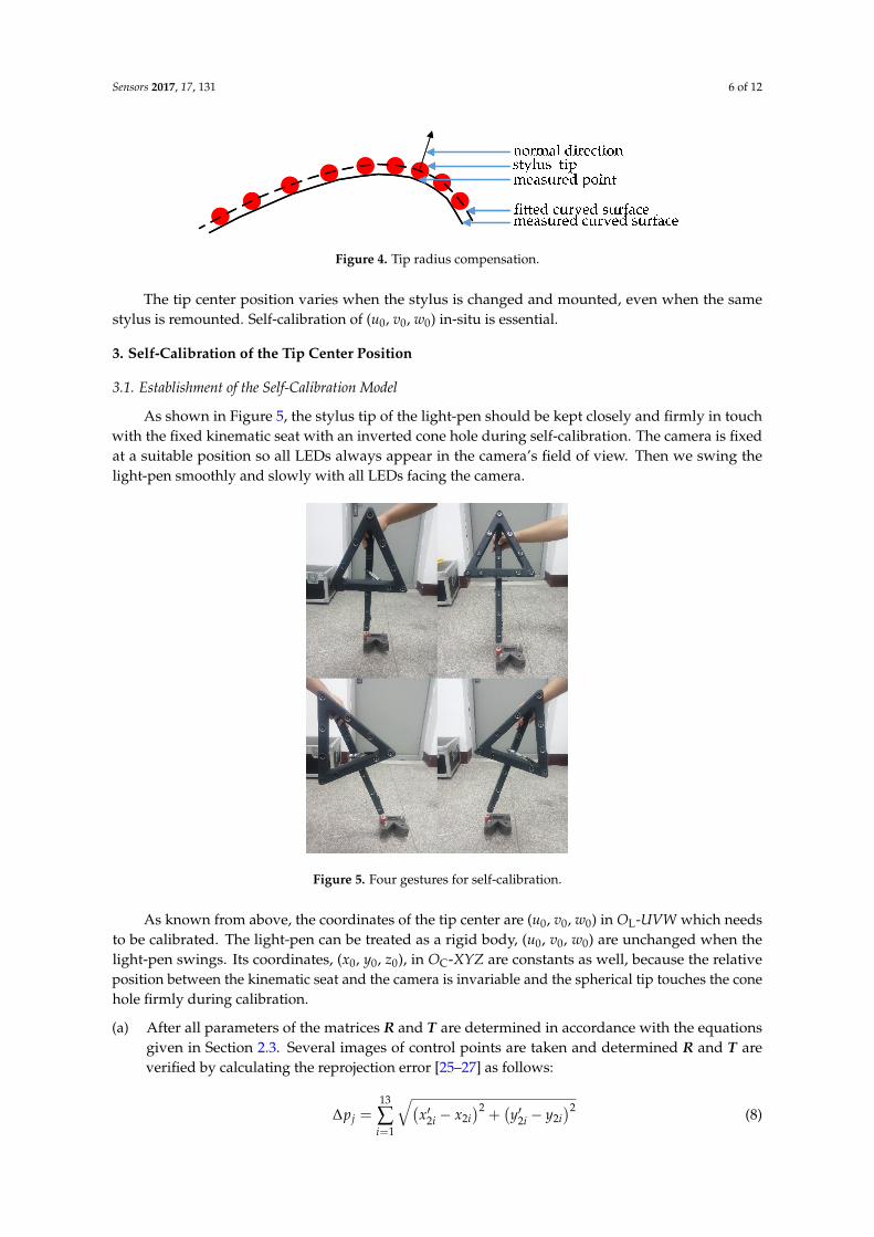
The coordinates of the measured point in OC-XYZ can be obtained with tip radius compensation.As shown in Figure 4, the enveloping surface method is always used to compensate the tip radius.The fitted curved surface could be obtained with center positions of the stylus tip. Then the measuredpoint’s position in OC-XYZ can be obtained by the corresponding stylus tip center position in OC-XYZ,its normal direction in OC-XYZ and the tip radius.
Sensors 2017, 17, 131 6 of 12
Sensors 2017, 17, 131 6 of 12
00 1 2 3
00 4 5 6
00 7 8 9 1
x
y
z
ux r r r t
vy r r r t
wz r r r t
= (7)
The coordinates of the measured point in OC-XYZ can be obtained with tip radius compensation. As shown in Figure 4, the enveloping surface method is always used to compensate the tip radius. The fitted curved surface could be obtained with center positions of the stylus tip. Then the measured point’s position in OC-XYZ can be obtained by the corresponding stylus tip center position in OC-XYZ, its normal direction in OC-XYZ and the tip radius.
Figure 4. Tip radius compensation.
The tip center position varies when the stylus is changed and mounted, even when the same stylus is remounted. Self-calibration of (u0, v0, w0) in-situ is essential.
3. Self-Calibration of the Tip Center Position
3.1. Establishment of the Self-Calibration Model
As shown in Figure 5, the stylus tip of the light-pen should be kept closely and firmly in touch with the fixed kinematic seat with an inverted cone hole during self-calibration. The camera is fixed at a suitable position so all LEDs always appear in the camera’s field of view. Then we swing the light-pen smoothly and slowly with all LEDs facing the camera.
Figure 5. Four gestures for self-calibration.
Figure 4. Tip radius compensation.
The tip center position varies when the stylus is changed and mounted, even when the samestylus is remounted. Self-calibration of (u0, v0, w0) in-situ is essential.
3. Self-Calibration of the Tip Center Position
3.1. Establishment of the Self-Calibration Model
As shown in Figure 5, the stylus tip of the light-pen should be kept closely and firmly in touchwith the fixed kinematic seat with an inverted cone hole during self-calibration. The camera is fixedat a suitable position so all LEDs always appear in the camera’s field of view. Then we swing thelight-pen smoothly and slowly with all LEDs facing the camera.
Sensors 2017, 17, 131 6 of 12
00 1 2 3
00 4 5 6
00 7 8 9 1
x
y
z
ux r r r t
vy r r r t
wz r r r t
= (7)
The coordinates of the measured point in OC-XYZ can be obtained with tip radius compensation. As shown in Figure 4, the enveloping surface method is always used to compensate the tip radius. The fitted curved surface could be obtained with center positions of the stylus tip. Then the measured point’s position in OC-XYZ can be obtained by the corresponding stylus tip center position in OC-XYZ, its normal direction in OC-XYZ and the tip radius.
Figure 4. Tip radius compensation.
The tip center position varies when the stylus is changed and mounted, even when the same stylus is remounted. Self-calibration of (u0, v0, w0) in-situ is essential.
3. Self-Calibration of the Tip Center Position
3.1. Establishment of the Self-Calibration Model
As shown in Figure 5, the stylus tip of the light-pen should be kept closely and firmly in touch with the fixed kinematic seat with an inverted cone hole during self-calibration. The camera is fixed at a suitable position so all LEDs always appear in the camera’s field of view. Then we swing the light-pen smoothly and slowly with all LEDs facing the camera.
Figure 5. Four gestures for self-calibration. Figure 5. Four gestures for self-calibration.
As known from above, the coordinates of the tip center are (u0, v0, w0) in OL-UVW which needsto be calibrated. The light-pen can be treated as a rigid body, (u0, v0, w0) are unchanged when thelight-pen swings. Its coordinates, (x0, y0, z0), in OC-XYZ are constants as well, because the relativeposition between the kinematic seat and the camera is invariable and the spherical tip touches the conehole firmly during calibration.
(a) After all parameters of the matrices R and T are determined in accordance with the equationsgiven in Section 2.3. Several images of control points are taken and determined R and T areverified by calculating the reprojection error [25–27] as follows:
∆pj =13
∑i=1
√(x′2i − x2i
)2+(y′2i − y2i
)2 (8)
Sensors 2017, 17, 131 7 of 12
The re-projected feature points (x2i’, y2i’) (i = 1~13) are obtained from pre-calibrated (ui, vi, wi)and the calculated matrices R, T. (xij”, yij”, zij”) are defined from Equation (9) given below. j isthe serial number of image. For assuring the required accuracy of calibration it is suggested totake at least seven images.It is known that the center positions of feature points can be determined more accurately whenthe light-pen is vertical than it is slant. When the pitch angle of the light-pen is small duringthe calibration, ∆pj will be small. However, the variations of (xij”, yij”, zij”) will be small as well,and it will lead to large errors in solving the equations. Conversely, when the pitch angle of thelight-pen is big, ∆pj will be big too. So two threshold values, Q1 < Q2, should be given for ∆pj tomake the pitch angle of the light-pen within a suitable range and to obtain eligible parameters ofthe matrices R, T.
(b) In OC-XYZ, the distance between the center of each LED and the tip center di (i = 1~13), and(x0, y0, z0) can be determined by solving the following equation using the nonlinear least squaregeneralized inverse method:
(x′′ij − x0)2+ (y′′ij − y0)
2+ (z′′ij − z0)
2= di
2 (9)
where (xij”, yij”, zij”) are coordinates of the center of the i-th LED in OC-XYZ system in thej-th image.
(c) Because of unavoidable errors in calibration, the distance between the center of the i-th LED andthe center of the probe tip cannot be the same as di calculated from Equation (9). ∆dj of the j-thimage is the sum of the absolute values of the differences between these two distances in the j-thimage. Two threshold values Q3, Q4 are given for ∆dmax, the maximum of all ∆dj, and variationof ∆dmax defined in Equation (10):
∆dj =13∑
i=1
∣∣∣∣∣√(
x′′ij − x0
)2+(
y′′ij − y0
)2+(
z′′ij − z0
)2− di
∣∣∣∣∣∆dmax = max
(∆dj) (10)
(d) As the distances, di (i = 1~13), are invariable in both OL-UVW and OC-XYZ, all 13 equationsshown in Equation (11) can be solved in the same way as in OL-UVW:
(ui − u0)2 + (vi − v0)
2 + (wi − w0)2 = di
2 (i = 1~13) (11)
In this way, the stylus tip center position of the light-pen in OL-UVW, (u0, v0, w0), canbe self-calibrated.
3.2. Calibration Steps
(a) To process one of the image and calculate the matrices Rj, Tj from Equations (1)–(6) and then todetermine (x2i’, y2i’) and (xij”, yij”, zij”) (i = 1~13, j ≥ 7) from Equations (2)–(4). To compute ∆pj inEquation (8) and save the parameters of Rj, Tj if Q1 < ∆pj < Q2. Otherwise ignore this photo.
(b) After at least seven eligible images are obtained, 13 distances di (i = 1~13) and (x0, y0, z0) can bedetermined from Equation (9).
(c) To calculate ∆dmax from Equation (10) and remove the image in which ∆dj is the biggest, andthen to capture one more image and go back to step (a). After that, a new ∆dmax is obtained.If this new ∆dmax < Q3 and the difference between two ∆dmax obtained from adjacent seveneligible photos is less than Q4, then distances di (i = 1~13) are considered as valid ones. Otherwise,similarly, to give up the image in which ∆dj is the biggest, and to capture one more image and goback to step (a).

Sensors 2017, 17, 131 8 of 12
(d) To determine the coordinates of the tip center in OL-UVW, (u0, v0, w0) from Equation (11) basedon eligible di.
4. Experiments
Repeatability tests of tip center position self-calibration at different distances and experiments formeasuring a circle and a gauge block have been carried out in a lab environment with the temperatureabout 20 ◦C.
4.1. Repeatability Tests of Tip Center Position Self-Calibration
By using the method mentioned above, the tip center positon of the light-pen has been self-calibratedten times to test the repeatability of the method proposed in this paper. The test results are given inTable 1.
Table 1. Repeatability test of self-calibration for (u0, v0, w0).
Test u0 (mm) v0 (mm) w0 (mm) Photos Needed
1 −2.019 −70.639 −16.643 1802 −1.964 −70.620 −16.657 1583 −2.017 −70.678 −16.629 2304 −1.970 −70.671 −16.655 2065 −1.991 −70.633 −16.617 1626 −1.988 −70.658 −16.636 1587 −1.973 −70.683 −16.612 1158 −1.953 −70.685 −16.634 1329 −1.966 −70.688 −16.645 11110 −2.037 −70.675 −16.632 276
Ave −1.988 −70.663 −16.636Std 0.027 0.023 0.014
Range 0.085 0.068 0.045
As shown in Table 1, the average value (Ave for short), the standard deviation (Std for short)and the range (the difference between the maximum and minimum value) of the calibrated tip centerpositon, as well as the total number of photos needed for particular calibration, are presented. It canbe seen that the dispersion range is (0.085, 0.068, 0.045) (mm) with the standard deviation (0.027,0.023, 0.014) (mm) in the U, V and W directions, respectively. It shows the repeatability of theself-calibration method based on invariable distances could meet the needs of measurement systemswith submillimeter accuracy. The total number of photos cannot be the same during each calibration,for that the number will be affected by many factors, such as the proficiency of experiment operator andsome others. However, less than 300 photos are needed and it takes less than 2 min for each calibration,which shows that the proposed method of self-calibration has the advantage of high efficiency.
During the calibration, the distance between the camera and the kinematic seat or the light-penshould be suitable. If it is too short, brightness of feature points is too high to obtain their centerpositions accurately, even with the dynamic adjustment algorithm of feature points, whereas if thedistance is too long, the solution accuracy for the LPCMM system will decrease. More images areneeded for the self-calibration described above with the increase of the distance. In the repeatabilityexperiment above, the camera keeps about 1.4 m away from the kinematic seat. However, this distancecannot be the same in each practical self-calibration. Table 2 shows the results of self-calibration atdifferent distances. The average values, the standard deviations and the ranges of ten tests for eachdistance are listed. In Table 2, the dispersion ranges of the average u0, v0, w0 at different distancesare (0.084, 0.108, 0.094) (mm) with the standard deviations (0.030, 0.035, 0.042) (mm) in U, V andW directions, respectively, which is acceptable. From the table, it can be seen that the absolute values ofu0 and v0 become bigger and bigger as the distance increases, while the value of w0 has no significant

Sensors 2017, 17, 131 9 of 12
changes. It might be caused by the error in camera focal length calibration. Some deep studiesare needed.
Table 2. Results of self-calibration for (u0, v0, w0) at different distances (mm).
DistanceAve Std Range
u0 v0 w0 u0 v0 w0 u0 v0 w0
1.2 m −1.974 −70.633 −16.648 0.008 0.029 0.037 0.020 0.063 0.0851.4 m −1.988 −70.663 −16.636 0.027 0.023 0.014 0.085 0.068 0.0451.6 m −1.991 −70.678 −16.554 0.015 0.018 0.003 0.037 0.039 0.0081.8 m −2.011 −70.682 −16.559 0.040 0.015 0.040 0.094 0.035 0.0982.0 m −2.059 −70.741 −16.559 0.042 0.066 0.058 0.090 0.163 0.136Std 0.030 0.035 0.042
Range 0.084 0.108 0.094
4.2. Measurement Experiments of the System with the (U0, V0, W0) Self-Calibrated
In order to test the accuracy of the self-calibration method based on invariable distances, severalmeasurement experiments are performed. A circle shown in Figure 6 and a gauge block were measuredwith the self-calibrated values of (u0, v0, w0) equal to (−1.988, −70.663, −16.636) (mm) in the U, V, Wdirections, respectively.
Sensors 2017, 17, 131 9 of 12
calibration, which shows that the proposed method of self-calibration has the advantage of high efficiency.
During the calibration, the distance between the camera and the kinematic seat or the light-pen should be suitable. If it is too short, brightness of feature points is too high to obtain their center positions accurately, even with the dynamic adjustment algorithm of feature points, whereas if the distance is too long, the solution accuracy for the LPCMM system will decrease. More images are needed for the self-calibration described above with the increase of the distance. In the repeatability experiment above, the camera keeps about 1.4 m away from the kinematic seat. However, this distance cannot be the same in each practical self-calibration. Table 2 shows the results of self-calibration at different distances. The average values, the standard deviations and the ranges of ten tests for each distance are listed. In Table 2, the dispersion ranges of the average u0, v0, w0 at different distances are (0.084, 0.108, 0.094) (mm) with the standard deviations (0.030, 0.035, 0.042) (mm) in U, V and W directions, respectively, which is acceptable. From the table, it can be seen that the absolute values of u0 and v0 become bigger and bigger as the distance increases, while the value of w0 has no significant changes. It might be caused by the error in camera focal length calibration. Some deep studies are needed.
Table 2. Results of self-calibration for (u0, v0, w0) at different distances (mm).
Distance Ave Std Range
u0 v0 w0 u0 v0 w0 u0 v0 w0 1.2 m −1.974 −70.633 −16.648 0.008 0.029 0.037 0.020 0.063 0.085
1.4 m −1.988 −70.663 −16.636 0.027 0.023 0.014 0.085 0.068 0.045
1.6 m −1.991 −70.678 −16.554 0.015 0.018 0.003 0.037 0.039 0.008
1.8 m −2.011 −70.682 −16.559 0.040 0.015 0.040 0.094 0.035 0.098
2.0 m −2.059 −70.741 −16.559 0.042 0.066 0.058 0.090 0.163 0.136
Std 0.030 0.035 0.042
Range 0.084 0.108 0.094
4.2. Measurement Experiments of the System with the (U0, V0, W0) Self-Calibrated
In order to test the accuracy of the self-calibration method based on invariable distances, several measurement experiments are performed. A circle shown in Figure 6 and a gauge block were measured with the self-calibrated values of (u0, v0, w0) equal to (−1.988, −70.663, −16.636) (mm) in the U, V, W directions, respectively.
Figure 6. The measured circle. Figure 6. The measured circle.
The diameter of the circle measured by the CMM equals to 63.521 mm, taken as its true value.The maximum permissible error (MPE for short) of the CMM is 2.3 + 3.3 L/1000 (µm) where L is themeasured length in mm. The circle was measured at five different positions and ten times at eachposition while the distance between the camera and the light-pen changes from 1.5 m to 9 m. The testresults are given is Table 3. The standard deviation and the dispersion range increase with the increaseof distance. The maximum absolute error (Abs for short) is 0.083 mm, which indirectly proves thevalidity of the self-calibration method.
Similar experiments have been performed by measuring a gauge block of 500 mm with uncertainty±2.20 µm. The experimental results are shown in Table 4. The largest error in its absolute value is−0.119 mm measured at distance of 1.5 m. The length of the gauge block is obtained by measuringseveral points on its two end surfaces. The images of these points are near the boundary of the imageplane, where the distortion errors are quite large even after corrections. However, the maximumabsolute error is still acceptable, that indirectly verifies the validity of the self-calibration method again.

Sensors 2017, 17, 131 10 of 12
Table 3. Repeatability test for the circle diameter (in mm) measured at different distances.
Distance 1.5 m 3 m 5 m 7 m 9 m
1 63.595 63.603 63.550 63.605 63.4272 63.633 63.608 63.658 63.627 63.3383 63.636 63.679 63.582 63.546 63.3244 63.602 63.673 63.474 63.619 63.7445 63.616 63.548 63.584 63.627 63.6256 63.576 63.549 63.629 63.489 63.5627 63.594 63.583 63.588 63.603 63.4868 63.584 63.616 63.560 63.470 63.4899 63.590 63.560 63.516 63.412 63.553
10 63.617 63.555 63.619 63.729 63.355Ave 63.604 63.597 63.576 63.573 63.490Abs 0.083 0.076 0.055 0.052 −0.031Std 0.019 0.046 0.051 0.089 0.128
Range 0.059 0.131 0.184 0.317 0.420
Table 4. Repeatability tests of measuring the length of a gauge block (in mm) at different distances.
Distance 1.5 m 3 m 5 m 7 m 9 m
1 499.840 499.965 500.048 500.087 499.9272 499.874 499.960 500.036 500.127 500.0483 499.871 499.949 499.995 500.080 499.9484 499.919 499.960 500.035 499.993 499.8945 499.888 499.946 500.025 500.073 499.8736 499.900 499.921 500.037 499.965 499.9257 499.847 500.003 500.052 500.077 499.9708 499.874 499.983 499.996 500.046 499.8559 499.911 499.982 499.994 499.992 500.028
10 499.889 499.959 500.018 500.008 499.992Ave 499.881 499.963 500.024 500.045 499.946Abs −0.119 −0.037 0.024 0.045 −0.054Std 0.024 0.022 0.021 0.050 0.061
Range 0.078 0.082 0.058 0.162 0.193
5. Conclusions
A new convenient method for stylus tip center position self-calibration based on invariabledistances in the LPCMM is presented in this paper. Only a kinematic seat with an inverted conehole is used and several images of control points are required to take during the self-calibration.The system structure and model of the whole system are given. The model and steps of self-calibrationare discussed in detail. To verify the effectiveness of the proposed method repeatability tests atdifferent distances and experiments by measuring a circle and a gage block have been carried out.Test results are satisfactory and show that the LPCMM system with the calibrated light-pen couldrealize submillimeter in-situ measurements. Further studies will be carried out in the real industrialfield to apply it in practice.
Acknowledgments: The authors wish to thank the State Administration of Science, Technology and Industry forNational Defense of China for the financial support through the project JSJL2014206B001. The authors also wishto thank Guoxiong Zhang for his great help on the revision of the manuscript.
Author Contributions: Rui Zhang and Shugui Liu conceived the self-calibration model; Sen Wang andXuanxiao Song designed and performed the experiments; Rui Zhang analyzed the data and wrote the paper.
Conflicts of Interest: The authors declare no conflict of interest.

Sensors 2017, 17, 131 11 of 12
References
1. Zhang, G.X. Coordinate Measuring Machines; Tianjin University Press: Tianjin, China, 1999; pp. 18–27.2. Calvo, R.; D’Amato, R.; Gómez, E.; Domingo, R. Integration of error compensation of coordinate measuring
machines into feature measurement: Part 1—Model development. Sensors 2016, 16, 1610. [CrossRef][PubMed]
3. Estler, W.T.; Edmundson, K.L.; Peggs, G.N.; Parker, D.H. Large-scale metrology—An update. CIRP Ann.Manuf. Technol. 2002, 51, 587–609. [CrossRef]
4. Jorge, S.; David, G.; Carlos, C.; Albajez, J.A.; Aguilar, J.J. Modelling and calibration technique of lasertriangulation sensors for integration in robot arms and articulated arm coordinate measuring machines.Sensors 2009, 9, 7374–7396.
5. Shi, G.; Wang, W. Single laser complex method to improve the resolution of FMCW laser ranging. J. InfraredMillim. Waves 2016, 35, 363–367.
6. Zhou, N.; An, Z.Y.; Li, L.J.; Zhu, Y. IGPS measurement network multi-station arrangement design.Appl. Mech. Mater. 2013, 443, 223–227. [CrossRef]
7. Franceschini, F.; Maisano, D.; Mastrogiacomo, L. Mobile spatial coordinate measuring system (MSCMS) andCMMs: A structured comparison. Int. J. Adv. Manuf. Technol. 2008, 42, 1089–1102. [CrossRef]
8. Wang, X.F.; Qiu, Z.R.; Yang, C.; Qian, Z.Y.; Chen, H.L. Calibration method for test sieves based on videomeasuring machine. J. Data Acquis. Process. 2013, 28, 257–260.
9. Zhang, Z.J.; Che, R.S.; Huang, Q.C.; Shun, Y.Q. Probe imaging vision coordinate measuring system composingmodeling and solving. J. Harbin Inst. Technol. 1999, 31, 69–73.
10. Liu, S.G.; Peng, K.; Huang, F.S.; Zhang, G.X.; Li, P. A portable 3D vision coordinate measurement systemusing a light pen. Key Eng. Mater. 2005, 295–296, 331–336. [CrossRef]
11. Qin, D.H. Research on the Technology and System of Portable Light Pen Coordinate Measurement System.Ph.D. Thesis, Huazhong University of Science and Technology, Wuhan, China, 2009.
12. Xie, Z.X.; Han, Z.H.; Gao, X. Key technologies of monocular vision measurement system with light pen.Chin. Opt. 2013, 6, 780–787.
13. Tsai, R. A versatile camera calibration technique for high-accuracy 3D machine vision metrology usingoff-the-shelf TV cameras and lenses. IEEE J. Robot. Autom. 1987, 3, 323–344. [CrossRef]
14. Zhang, Z.Y. A flexible new technique for camera calibration. IEEE Trans. Pattern Anal. Mach. Intell. 2000, 22,1330–1334. [CrossRef]
15. Zhang, Z.Y. Camera calibration with one-dimensional objects. IEEE Trans. Pattern Anal. Mach. Intell. 2004,26, 892–899. [CrossRef] [PubMed]
16. Zhang, Y.J.; Zhang, Z.X.; Zhang, J.Q. Camera calibration using 2D-dlt and bundle adjustment with planarscenes. Geomat. Inform. Sci. Wuhan Univ. 2002, 27, 566–571.
17. Liu, S.G.; Jiang, Z.Z.; Dong, Y.H.; Zhang, H.L. Sub-regional camera calibration based on moving light target.Opt. Precis. Eng. 2014, 22, 259–265.
18. Heikkilä, J. Geometric camera calibration using circular control points. IEEE Trans. Pattern Anal. Mach. Intell.2000, 22, 1066–1077. [CrossRef]
19. Svoboda, T.; Martinec, D.; Pajdla, T. A convenient multicamera self-calibration for virtual environments.Presence 2006, 14, 407–422. [CrossRef]
20. Alblalaihid, K.; Kinnell, P.; Lawes, S.; Desgaches, D.; Leach, R. Performance assessment of a new variablestiffness probing system for micro-CMMs. Sensors 2016, 16, 492. [CrossRef]
21. Fu, S.; Zhang, L.Y.; Ye, N.; Zhang, W.Z.; Liu, S.L. A flexible approach to light pen calibration fora monocular-vision-based coordinate measuring system. Meas. Sci. Technol. 2014, 25, 1–8. [CrossRef]
22. Liu, S.G.; Zhang, H.L.; Dong, Y.H.; Tang, S.L.; Jiang, Z.Z. Portable light pen 3D vision coordinate measuringsystem—Probe tip center calibration. Meas. Sci. Rev. 2013, 13, 194–199. [CrossRef]
23. Zhang, R.; Liu, S.G.; Wang, H.Y. Wireless control for pointolite in light-pen CMMs. Appl. Mech. Mater. 2014,602–605, 2217–2220. [CrossRef]
24. Xu, S.L.; Ma, E.N. Commonly Used Algorithm for Assembly (C/C++ Language to Describe), 3rd ed.; TsinghuaUniversity Press: Beijing, China, 2013; pp. 204–210.

Sensors 2017, 17, 131 12 of 12
25. Gargallo, P.; Prados, E.; Sturm, P. Minimizing the reprojection error in surface reconstruction from images.In Proceedings of the IEEE the 11th International Conference on Computer Vision, Rio de Janeiro, Brazil,14–20 October 2007; pp. 1–8.
26. Haro, G.; Pardàs, M. Shape from incomplete silhouettes based on the reprojection error. Image Vis. Comput.2010, 28, 1354–1368. [CrossRef]
27. Rukubayihunga, A.; Didier, J.Y.; Otmane, S. Reprojection error as a new metric to detectassembly/disassembly maintenance tasks. In Proceedings of the 5th International Conference on ImageProcessing Theory, Tools and Applications, Orléans, France, 10–13 November 2015; pp. 513–518.
© 2017 by the authors; licensee MDPI, Basel, Switzerland. This article is an open accessarticle distributed under the terms and conditions of the Creative Commons Attribution(CC-BY) license (http://creativecommons.org/licenses/by/4.0/).