Embed Size (px)
Citation preview

Research ArticleStudy on Corrosion Characteristics of Concrete-FilledCFRP-Steel Tube Piles under Hygrothermal Environment
Honghan Dong ,1,2 Yujue Zhou,3 and Ning Zhuang 2
1Department of Civil Engineering, MOE Key Laboratory of Soft Soils and Geoenvironmental Engineering, Zhejiang University,Hangzhou 310058, China2Jiangsu Key Laboratory of Coast Ocean Resources Development and Environment Security, Hohai University,Nanjing 210098, China3College of Civil Engineering, Tongji University, Shanghai 200092, China
Correspondence should be addressed to Ning Zhuang; [email protected]
Received 3 September 2019; Revised 27 December 2019; Accepted 29 January 2020; Published 25 February 2020
Academic Editor: Aniello Riccio
Copyright © 2020 Honghan Dong et al. +is is an open access article distributed under the Creative Commons AttributionLicense, which permits unrestricted use, distribution, and reproduction in any medium, provided the original work isproperly cited.
+e corrosion damage of pile foundations caused by a hygrothermal environment is a significant factor that influences the servicelife of high-pile wharf structures. +e concrete-filled CFRP-steel tube (CFRP-CFST) pile is a composite structure composed ofexternal Carbon Fiber-Reinforced Polymer (CFRP) sheets and inner concrete-filled steel tubes. It has a high-bearing capacity andexcellent corrosion resistance and is an ideal structure for pile foundations in aggressive environments. In this paper, twelveCFRP-CFSTpile specimens with diameters of 114mm and heights of 1200mm and another forty-two CFRP-steel plate specimenswith CFRP widths of 30–50mm were built. A high hot and humid environment simulation system was designed to conductcorrosion experiments with these specimens. At different theoretical corrosion degrees, the half-cell potential, corrosion products,corrosion expansion, and adhesive property were investigated. +e test results showed an obvious increase in the mechanicalproperties and corrosion resistance when the concrete-filled steel tube was externally bonded to CFRP sheets. +e experimentalresults show that the CFRP-CFST pile is an effective way to protect piles from corrosion and can be widely used for high-pilewharfs in aggressive environments.
1. Introduction
+e concrete-filled steel tube (CFST) pile is a widely usedcomposite structure. Concrete has excellent compressiveresistance but poor tensile resistance [1]. Steel tubes haveexcellent flexural properties but easily succumb to bucklingfailure under high pressure. +e strength and ductility ofCFSTpiles may rapidly decrease due to material corrosion inhot and humid environments. CFRP composites are con-sidered as a new material to overcome the weakness of CFSTpiles due to their higher strength, favorable strength-to-weight ratio, and excellent corrosion resistance. +is hasresulted in the appearance of a new structure, the concrete-filled CFRP-steel tube (CFRP-CFST) pile, which has a high-bearing capacity and excellent corrosion resistance.
Externally bonded CFRP sheets can apply circular pressureto constrain concrete and steel tube deformation and im-prove the mechanical behaviors of CFRP-CFST piles. CFRPsheets also have excellent durability to effectively prevent theerosion of corrosive media under hygrothermal environ-ments [2]. In addition, CFRP can directly reduce the amountof steel material and the construction difficulty [3].
+e CFRP-CFST pile of high-pile wharfs has threecorrosion zones: the atmospheric zone, the dry andwet alternating zone, and the underwater zone. Oxygen andwater are indispensable for the occurrence and developmentof corrosion [4–7]. +e underwater zone lacks enoughoxygen, and the water supply in the atmospheric zone isinsufficient. +erefore, the dry and wet alternating zone ismostly prone to corrosion because it is wetted periodically
HindawiAdvances in Materials Science and EngineeringVolume 2020, Article ID 4849038, 11 pageshttps://doi.org/10.1155/2020/4849038

by tidal levels and has an adequate supply of water andoxygen. For CFRP-CFSTpiles, the internal steel pipe will becorroded quickly when the outer CFRP sheet is penetratedby the corrosion medium. +is will seriously reduce thebearing capacity and service life of the CFRP-CFST pile. Atpresent, studies have mainly focused on the mechanicalproperties of CFRP-CFSTpiles [8]. For example, some staticload experiments have been conducted to investigate theaxial and flexural behavior of CFRP-CFST piles [9–11]. +estudies reported that externally bonded CFRP would im-prove the bearing capacity and ductility to certain degrees.Based on the limit equilibrium theory, a formula for cal-culating the bearing capacity of damaged CFRP-CFSTmembers before and after compression was presented, andthe calculated results were in good agreement with exper-imental data [12–15]. Other tests showed that the failurepattern was steel tube buckling, and CFRP was pulled offunder static loading [16]. +e bending, shear, and torsionproperties were related to the bonding direction and numberof CFRP bonding layers [17].
In addition to the above studies, experiments have beenconducted to investigate the improvement of the mechanicalproperties of piles [18]. However, little information has beenfound in the literature regarding the corrosion properties ofCFRP-CFST piles under the hygrothermal environment ofthe ocean [19]. +erefore, the main objective of this study isto research the corrosion characteristics of CFRP-CFST pilesunder the hot and humid environments.
2. Experimental Program
2.1. Test Program. Twelve CFRP-CFST pile specimens werebuilt (Figure 1) in the laboratory. Each pile specimen wasdivided into three zones: an atmospheric zone, a dry andwet alternating zone, and an underwater zone, as shown inFigure 2. All pile specimens were divided into three groups,and each group included four pile specimens according tothe degree of corrosion (0%, 5%, 10%, and 15%), as sum-marized in Table 1. +e geometric parameters of the pilespecimens are shown in Table 2. Each pile specimen wasmounted with nine strain gauges to monitor the deforma-tion caused by the expansion of corrosion, as shown inFigure 2. +e surface of the pile was covered with CFRPsheets, leaving no gaps. It was necessary to polish the surfaceof the steel pipes with an angle mill before pasting the CFRPsheets. After that, the entire outer surface of the steel pipewas repeatedly wiped with a nonwoven cloth and soaked inan acetone solution to remove the moisture and dust fromthe surface of the steel pipe. +en, the CFRP sheets werepasted from the bottom to the top of a pile, and the lap widthbetween the adjacent layers was not less than 15 cm. Finally,the outer surface of the CFRP sheets was coated with glue,and the specimens were left in a cool and ventilated place forover 24 hours.
2.2. Material Properties. +e concrete mix proportion byweight was aggregate : sand : water : cement � 2.20 :1.35 :1.00 : 0.35. As the pile foundation model was constructed,
standard test blocks (10mm × 10mm× 10mm) for testingthe compressive strength of the concrete were made. +econcrete pouring process was continuous. No concrete waspoured into a space of approximately 2 cm from the top ofthe steel tube to facilitate the connection of the powersupply during the accelerated corrosion test. Before the
Figure 1: CFRP-CFST pile specimens.
CFRP-CFST pile
Position of strain gauge
Atmospheric zone
Dry and wet alternating zone
Underwater zone
400mm
400mm
400mm
Figure 2: Corrosion zones of pile.
Table 1: Test program.
Groups of CFRP-CFST pileCorrosion degree (% mass loss)0 5% 10% 15%
Without CFRP U-0 U-5 U-10 U-15One layer of CFRP P1-0 P1-5 P1-10 P1-15Two layers of CFRP P2-0 P2-5 P2-10 P2-15
2 Advances in Materials Science and Engineering

ballast tests, it was necessary to use plastering mortar forsupplementary casting. +e concrete had an average 28-daycompressive strength of 36.6MPa based on compressivestrength tests [20]. +e yield strength of the steel tube was235MPa based on tensile tests. +e main properties of theCFRP sheets and the epoxy resin adhesive are shown inTables 3 and 4, respectively, according to the factorystandards.+e epoxy resin adhesive was composed of gradeA and grade B of glue. +e two grades were mixed at a massratio of 3 : 1 with a hand-held electric mixer to a uniformstate when used [21].
2.3. Preparing the Test. CFRP-CFST pile specimens werekept in the tank (Figure 3) and subjected to wet-dry cycles byhigh chloride seawater, the chemical composition of which isshown in Table 5.+e tank was in the room and kept at roomtemperature. +e difference between high and low tides was400mm, and the water level was changed gradually every 12hours using a water pump and a floating switch to simulatethe tidal range zone, as shown in Figure 4. +e water levelcirculation system used a remote automatic control, andwater was replenished regularly to make up for evaporation[22].
To achieve corrosion within a reasonable time, theaccelerated corrosion technique based on Faraday’s law wasused in the laboratory. In this technique, a constant currentsystem is built, and a DC galvanostatic power supply is usedto provide the desired current (Figure 3). +e current in theexperiment was set as 166mA.+e time required for variousdegrees of corrosion was calculated based on Faraday’s law[23, 24]. Faraday’s law along with the induced currentcalculations is presented in the following:
ml �M · i · Sa · T
ZF, (1)
where ml is weight of steel consumed;M is atomic weight ofmetal (56 g for Fe); i is current density level; T is time; Z isionic charge (Fe⟶ Fe2+ + 2e− )� 2; F is Faraday’s constant;and Sa is surface zone of the corroded steel.
3. Experimental Results and Discussions
3.1. Half-Cell Potential. +e half-cell potential measurementis one of the most widely used nondestructive methods tomonitor and assess corrosion. In essence, the measuredpotential value is the internal potential difference of themicrosection of the steel tube. +is potential difference willgenerate a weak current in the microsection of the steel tube,which leads to electrochemical corrosion. Compared toother methods such as the rotating disk electrode (RDE), thehalf-cell potential measurement has its own advantages. It ispossible and sensitive to examine the small current inside thesteel cube even at the common fuel cell working ranges. In
addition, it is easy to operate and measure the same positionrepeatedly to obtain the average value and thus ensure arelatively high accuracy of the results.
In this paper, the CANIN+ corrosion detector waschosen as the electric potential measuring instrument [25].To detect the potential values, the Cu-CuSO4 solution andthe pile specimens were combined to form a battery system.Once the steel tube was corroded and the charge was ex-changing, the current and polarization occurred on thecontact surface. During polarization, the metal anode po-tential increased, and the cathode potential decreased untilthe potential was balanced. It is generally agreed that thehalf-cell potential measurements can be interpretedaccording to Table 6 [26].
+e half-cell potential values of the CFRP-CFST pilespecimens were increased with the degree of corrosion, asshown in Figure 5. +e average potential of the dry andwet alternating zone was smaller than that of the othercorrosion zones. +is indicated that the dry andwet alternating zone was in a more active corrosion statebecause it had sufficient oxygen and water. For the pilespecimens (U-0, U-5, U-10, and U-15) without CFRP sheets,the average electric potential values corresponding to dif-ferent corrosion degrees (0%, 5%, 10%, and 15%) in the dryand wet alternating zone were − 80mV, − 349mV, − 639mV,and − 709mV, respectively. +is showed that the pilespecimens were in the corrosion state from the corrosiondegree of 5%.
For piles specimens (P1-5, P1-10, and P1-15) with onelayer of CFRP sheets, the half-cell potential values signifi-cantly decreased. +e average half-cell potential valuescorresponding to different corrosion degrees (5%, 10%, and15%) in the dry and wet alternating zone were − 157mV,− 403mV, and − 432mV, respectively, which were approx-imately 55%, 33%, and 39% more positive compared to thepiles specimens without CFRP sheets. +e potential valueshowed that the dry and wet alternating zone had a greaterthan 90% probability of no active corrosion at 5%. +e half-cell potential values of piles specimens P1-10 and P1-15 werevery close when the corrosion degree was at the high levels of10% and 15%. +e CFRP sheet of the CFRP-CFST pilespecimens could prevent the penetration of the corrosivemedium, which delayed the corrosion of the piles, partic-ularly at high degrees of corrosion.
For pile specimens (P2-0, P2-5, and P2-15) with twolayers of CFRP sheets, their half-cell potential values were allsmaller than those with one layer of CFRP sheets. However,their change trends were identical. +e corrosion potentialsin the dry and wet alternating zone were − 157mV, − 200mV,and − 246mV, respectively, which were 63%, 70%, and 65%more positive compared with the piles specimens withoutCFRP sheets at corrosion degrees of 5%, 10%, and 15%,respectively. +is indicated that the electric potential of thepiles would decrease as the number of layers of CFRP sheets
Table 2: Geometric parameters of pile specimens.
Height (mm) Cross section diameter (mm) Steel tube thickness (mm)Pile specimens 1200 114 2.7
Advances in Materials Science and Engineering 3

increased. +e CFRP sheet had a significant effect ondelaying the corrosion degree of the CFRP-CFST pilespecimens.
3.2. Corrosion Expansion. As the steel tube of the CFRP-CFSTpile specimens corroded, the rust expanded more thansix times in volume compared with the steel. +e accu-mulation of products would produce the expansion stressthat caused the surface strain of the CFRP-CFST pilespecimens.+e arrangement of the strain gauges is shown inFigure 2. +ese strain gauges were applied to the surface ofthe CFRP, leaving no gaps, to measure the circumferentialmicrostrain of the model piles at the specified time node.+ey were arranged horizontally around the piles. Straindata were collected for increments of 5% in the theoreticalcorrosion rate.
As shown in Figure 6, the strains of the dry andwet alternating zone were more severe than those of theatmospheric zone and underwater zone, which was con-sistent with the variation of the half-cell potentials. +is alsoindicated that the dry and wet alternating zone was the mostprone to corrosion.
+e CFRP sheet could apply a constraining force to limitcorrosion expansion during the corrosion stage. For the pilespecimens with two CFRP layers, the maximum strain of the
Table 3: Properties of CFRP.
+ickness (mm) Tensile strength (MPa) Elasticity modulus (MPa) Ductility (%) Density (g/cm3) Tensile strain (×10− 6)0.11 3450 2.3 × 10⁵ 2.1 1.8 16650
Table 4: Properties of the epoxy resin adhesive.
Compressive strength (MPa) Tensile strength (MPa) Shear strength (MPa) Elasticity modulus (MPa)64.6 25.9 20.8 5.6 × 10³
Figure 3: Simulated environment and accelerating corrosion system.
Table 5: Chemical composition of seawater.
Chemical compound Concentration (g/L) Chemical compound Concentration (g/L)NaCl 24.53 NaHCO3 0.201MgCl2 5.2 KBr 0.101Na2SO4 4.09 H3BO3 0.027CaCl2 1.16 SrCl2 0.025KCl 0.695 NaF 0.003
Wat
er le
vel (
m)
5 10 15 20 250Time (h)
0.6
0.7
0.8
0.9
1.0
Figure 4: Simulated sea tidal cycles.
4 Advances in Materials Science and Engineering

dry and wet alternating zone was approximately 18%, 19%,and 26% smaller than that of the specimens with one CFRPlayer and 28%, 31%, and 37% smaller than that of thespecimens with no CFRP layer at corrosion degrees of 5%,10%, and 15%, respectively. +e strains of the piles woulddecrease as the number of CFRP sheet layers increased. +ehigher the lever of the corrosion degree, the clearer the effects.
3.3. Corrosion Products. +e composition of steel corrosionproducts has been studied bymany scholars. Research on thecorrosion products of iron and steel began with Evans’ localbattery theory in 1932 [27]. +en, the composition andstructural changes of steel corrosion products were studiedby many Japanese scholars during the period from 1940 to1960 [28]. After that, the electrochemical reactionmodel and
Table 6: Dependence between potential and corrosion probability.
Potential Probability of corrosionEcor< − 350mV Greater than 90% probability that corrosion is occurring− 350mV≤ Ecor≤ − 200mV Corrosion activity is uncertainEcor< − 200mV 90% probability that no corrosion is occurring (10% risk of corrosion)
U-0P1-5
U-5P2-5
Underwater zone
Dry and wet alternating zone
Atmospheric zone
100 150 200 250 300 35050Potential (-mV)
0
20
40
60
80
100
120
Hei
ght (
cm)
(a)
Underwater zone
Dry and wet alternating zone
Atmospheric zone
0
20
40
60
80
100
120
Hei
ght (
cm)
200 300 400 500 600 700 800100Potential (-mV)
U-10
P2-10P1-10
(b)
Underwater zone
Dry and wet alternating zone
Atmospheric zone
0
20
40
60
80
100
120
Hei
ght (
cm)
U-15
P2-15P1-15
300 400 500 600 700 800200Potential (-mV)
(c)
Figure 5: Measured half-cell potentials of pile specimens: (a) 5% corrosion degree, (b) 10% corrosion degree, and (c) 15% corrosion degree.
Advances in Materials Science and Engineering 5

the potential-pH diagram of FeOOH appeared in 1973 [29].Now, X-ray diffraction analysis (XRD) is treated as an ef-fective method. When an X-ray with a certain wavelength isirradiated on the surface of a crystalline material, the X-ray isblocked by the rehearsed regular particles and scattered. Dueto the corresponding and unique radiation reaction of thecrystal itself, the phase of the scattered ray is strengthened incertain directions. In this paper, XRD was used to analyzethe crystal formation of the corrosion products of the modelpiles at different corrosion stages [30].
+e corrosion composition and the corrosion-inducedexpansion were different during the corrosion stages. +emechanism of steel tube corrosion products is shown inFigure 7 [31]. +e element of Fe on the surface of the steelmatrix would first precipitate as green Fe2+ or FeOH+ andthen oxidize into c-FeOOH or α- FeOOH. At the same time,
Fe3O4 can also be produced. +rough analyzing the com-ponents of the corrosion products at different stages of pilecorrosion, we can fundamentally and indirectly verify thedegree of corrosion. Additionally, it is beneficial to developeffective reinforcement schemes with CFRP sheets, espe-cially for structures that have been in service for a certainnumber of years.
+e X-ray diffraction patterns of the dry andwet alternating zone at 5% and 10% corrosion degrees areshown in Figure 8. +e diffraction peaks were concentratedat angles of 2θ � 26.75°, 2θ � 35.71°, 2θ� 45.15°, 2θ� 46.35°,and 2θ� 62.24°, especially at angles of 2θ � 26.75° and2θ � 35.75° at a 10% corrosion degree. +e correspondingcomponents of these characteristic peaks were mainly Fe2O3,Fe3O4, α- FeOOH, and c-FeOOH. As the number of CFRPsheet layers increased, the peak diffraction tended to shift to
Underwater zone
Atmospheric zone
Dry and wet alternating zone
U-5P1-5P2-5
0
20
40
60
80
100
120H
eigh
t (cm
)
40 60 80 100 12020Strain (10–6)
(a)
Underwater zone
Dry and wet alternating zone
U-10P1-10P2-10
Atmospheric zone
0
20
40
60
80
100
120
Hei
ght (
cm)
40 60 80 100 120 140 160 18020Strain (10–6)
(b)
Underwater zone
Dry and wet alternating zone
U-15P1-15P2-15
Atmospheric zone
0
20
40
60
80
100
120
Hei
ght (
cm)
40 60 80 100 120 140 160 180 200 220 24020Strain (10–6)
(c)
Figure 6: Strains of piles at different corrosion degrees: (a) 5% corrosion degree, (b) 10% corrosion degree, and (c) 15% corrosion degree.
6 Advances in Materials Science and Engineering

the left; that is to say, the angle of the diffraction peaksbecame smaller. At the same time, the height of the dif-fraction peaks also decreased. It was also concluded fromFigure 8 that the number of diffraction peaks decreased asthe number of CFRP sheet layers increased, indicating thatan increase in the number of CFRP sheet layers could slowthe degree of corrosion of pile specimens because CFRPsheets prevent the invasion of aggressivemedia. On the otherhand, the property of α- FeOOH that was stable and had alow electrochemical activity was on the outside part of therust layer, which acted as a certain isolation layer [32]. +ediffraction peaks appeared at angles of 2θ � 21.25°,2θ� 26.15°, 2θ� 36.74°, 2θ� 47.15°, and 2θ� 64.04° at a 5%corrosion degree. +e corresponding components of thesecharacteristic peaks were the same as those for a 10%corrosion degree. Unlike the 10% corrosion degree, thediffraction peaks of α-FeOOH and c-FeOOH were smaller,which indicated a lower corrosion degree.
3.4. Bond Performance between CFRP and Steel Tubes.+e bond between the CFRP and the steel pipe is the weakestpart that has a direct impact on the mechanical properties ofpiles, and the strength of the bond property directly affectsthe reinforcement effect of CFRP. In addition, the bond isthe last defense once the carbon fiber is broken down by
corrosive ions during the service of the piles. It is necessaryto study the bond properties between the CFRP and the steeltubes [33].
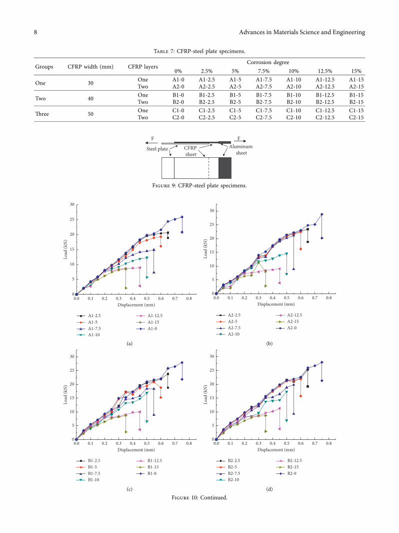
To study the bond performance between the CFRP andthe steel tubes in the piles, three groups of CFRP-steel platespecimens were prepared and corroded in the dry andwet alternating zone, as shown in Table 7. +e dimensions ofthe steel plate were as follows: 220mm in length, 70mm inwidth, and 3mm in thickness (Figure 9). +e properties ofthe steel plate were the same as those of the steel tubes of theCFRP-CFST pile. To eliminate the effect of width on theresults, the CFRP widths were set to 30mm, 40mm, and50mm. An accelerated corrosion technique based on Far-aday’s law was also used to corrode the CFRP-steel plates.+e load-displacement test of the CFRP-steel plate speci-mens was carried out on a universal test machine withdisplacement control. +e steel plate was connected to thealuminum plate with CFRP sheets of different widths(Figure 9). Successive loads were applied in stages on bothends of the specimen until apparent slip appeared.+e straingauges were pasted on the middle surface of the CFRPsheets. +e data of the corresponding loads were recordedfor every 0.05mm of displacement.
+e bond force to displacement of the pile specimens waslinear as shown in Figure 10. +e maximum bond forcedecreased as the corrosion degree increased. As the width of
Fe Fe2+
FeOH+
Fe(OH)2
Fe2+
1
9
2 Fe(OH)2
Fe3O4
3
γ-FeOOH
GR4
Ferrihydrite
α-FeOOH
5 6
7
8
Figure 7: Mechanism of the corrosion products of a steel pipe.
Without CFRP
One layer of CFRP
Two layers of CFRP
Inte
nsity
(a.u
.)
Δ
Δ
Δ
Δ
Δ
Δ
Δ
Δ
Δ
Δ
Δ Δ
Ⓡ
Ⓡ
Ⓡ
α-FeooHFe3O4
γ-FeooHFe2O3Δ
Ⓡ
Ⓡ Ⓡ
Ⓡ
20 60 705030 40 80102θ (degree)
(a)
Inte
nsity
(a.u
.)
Without CFRP
One layer of CFRP
Two layers of CFRP
Δ
Δ
ΔΔ
ΔΔΔ
ΔΔ
Δ
ΔΔΔΔΔ
Δ
Ⓡ
Ⓡ
ⓇⓇ
Ⓡ
Ⓡ Ⓡ
α-FeooHFe3O4
γ-FeooHFe2O3Δ
Ⓡ
20 30 40 50 60 70 80102θ (degree)
(b)
Figure 8: XRD pattern of corrosion products: (a) 5% corrosion degree and (b) 10% corrosion degree.
Advances in Materials Science and Engineering 7
Load
(kN
)
A1-2.5A1-5A1-7.5A1-10
A1-12.5A1-15A1-0
0.1 0.2 0.3 0.4 0.5 0.6 0.7 0.80.0Displacement (mm)
0
5
10
15
20
25
30
(a)
Load
(kN
)
A2-2.5A2-5A2-7.5A2-10
A2-12.5A2-15A2-0
0.1 0.2 0.3 0.4 0.5 0.6 0.7 0.80.0Displacement (mm)
0
5
10
15
20
25
30
(b)
Load
(kN
)
B1-2.5B1-5B1-7.5B1-10
B1-12.5B1-15B1-0
0.1 0.2 0.3 0.4 0.5 0.6 0.7 0.80.0Displacement (mm)
0
5
10
15
20
25
30
(c)
Load
(kN
)
B2-2.5B2-5B2-7.5B2-10
B2-12.5B2-15B2-0
0.1 0.2 0.3 0.4 0.5 0.6 0.7 0.80.0Displacement (mm)
0
5
10
15
20
25
30
(d)
Figure 10: Continued.
Table 7: CFRP-steel plate specimens.
Groups CFRP width (mm) CFRP layersCorrosion degree
0% 2.5% 5% 7.5% 10% 12.5% 15%
One 30 One A1-0 A1-2.5 A1-5 A1-7.5 A1-10 A1-12.5 A1-15Two A2-0 A2-2.5 A2-5 A2-7.5 A2-10 A2-12.5 A2-15
Two 40 One B1-0 B1-2.5 B1-5 B1-7.5 B1-10 B1-12.5 B1-15Two B2-0 B2-2.5 B2-5 B2-7.5 B2-10 B2-12.5 B2-15
+ree 50 One C1-0 C1-2.5 C1-5 C1-7.5 C1-10 C1-12.5 C1-15Two C2-0 C2-2.5 C2-5 C2-7.5 C2-10 C2-12.5 C2-15
Steel plate CFRP sheet
Aluminum sheet
F F
Figure 9: CFRP-steel plate specimens.
8 Advances in Materials Science and Engineering

the CFRP sheets was 30mm, the difference of the maximumbond forces was not obvious at low corrosion degrees of 0%and 2.5%. When the number of CFRP layers increased fromone to two, the ultimate bond strength increased by 16%,19%, and 32% at corrosion degrees of 5%, 10%, and 15%,respectively. However, the ultimate displacement of speci-men A2-15 was approximately 0.05mm smaller than that ofspecimen A1-15 at a corrosion of 15%.+e number of CFRPlayers had a significant effect on the bond strength, while ithad a small effect on the ultimate displacement with thegrowth of the corrosion degree.
For the CFRP sheets with widths of 40mm and 50mm,the maximum bond strength also decreased rapidly as thecorrosion degree increased. +e maximum bond strengthincreased when the number of CFRP sheet layers changedfrom one to two for the same CFRP sheet width. +e testresults showed that the rule of the maximum bond strengthchange was similar to that for a CFRP sheet width of 30mm.+e CFRP sheet could seal the pile specimens and isolatethem from the corrosive medium that would destroy theadhesive interface of the CFRP and steel tubes. Maintainingthe adhesive interface in a good condition was important tomaking full use of the restraining force of the CFRP toenhance CFRP-CFST pile load capacity. +e CFRP sheetcould not only increase the load capacity but also prevent thematerial from corroding compared with the CFST pile withno outer CFRP sheet.
4. Conclusions
+is paper presents the results of a test program that in-vestigated the resistance to corrosion of CFRP-CFST pilespecimens subjected to a simulated hygrothermal environ-ment. Based on the experimental results of this study, thefollowing conclusions were drawn.
+e CFRP sheet of the CFRP-CFST pile specimens couldseal the surface of the piles and prevent further ingression ofharmful substances into the pile. Piles provided excellentprotection against corrosion in terms of their corrosionstrain, half-cell potential, corrosion products, and adhesiveproperty as the number of CFRP layers increased.
+e dry and wet alternating zone was the most seriouscorrosion zone because it was wetted periodically by the tidallevel and had sufficient oxygen and water. +e averagepotential was smaller than that of the other two corrosionzones. +e half-cell potential of the piles decreased as thenumber of CFRP sheet layers increased, especially at highcorrosion degrees. Two layers of externally bonded CFRPsheets in the tidal range zone reduced the corrosion activityby up to 45% and 52% compared with one and no CFRPsheets, respectively, at a corrosion degree of 15%.
+e accumulation of products would produce the ex-pansion stress that caused surface strain of the CFRP-CFSTpile specimens. +e CFRP sheet of the CFRP-CFST pilespecimens could prevent the penetration of the corrosivemedium, which delayed the corrosion of the pile. +e strainsof the piles decreased as the number of CFRP sheet layersincreased. +e higher the lever of the corrosion degree, theclearer the effects.
+e corresponding components of the corrosion prod-ucts were mainly Fe2O3, Fe3O4, α- FeOOH, and c-FeOOHby diffraction peaks. It was also concluded that the numberof diffraction peaks decreased as the number CFRP sheetlayers increased. +is indicated that an increase in thenumber of CFRP sheet layers could slow the corrosiondegree of the pile specimens because the CFRP sheet pre-vented the invasion of the aggressive medium.
+e CFRP sheet could not only increase the load capacitybut also prevent the material from corroding.+emaximumbond force decreased as the corrosion degree increased.
0
5
10
15
20
25
30
Load
(kN
)
C1-2.5C1-5C1-7.5C1-10
C1-12.5C1-15C1-0
0.1 0.2 0.3 0.4 0.5 0.6 0.7 0.80.0Displacement (mm)
(e)
Load
(kN
)
C2-2.5C2-5C2-7.5C2-10
C2-12.5C2-15C2-0
0.1 0.2 0.3 0.4 0.5 0.6 0.7 0.80.0Displacement (mm)
0
5
10
15
20
25
30
(f )
Figure 10: Load-displacement of the CFRP-steel plate specimens. (a) One-layer CFRP with width of 30mm. (b) Two-layer CFRP with widthof 30mm. (c) One-layer CFRP with width of 40mm. (d) Two-layer CFRP with width of 40mm. (e) One-layer CFRP with width of 50mm.(f) Two-layer CFRP with width of 50mm.
Advances in Materials Science and Engineering 9

When the number of CFRP layers increased from one to two,the ultimate bond strength increased by 16%, 19%, and 32%at corrosion degrees of 5%, 10%, and 15%, respectively. +enumber of CFRP layers had a significant effect on the bondstrength, while it had little effect on the ultimate displace-ment with the growth of the corrosion degree.
Data Availability
+e data used to support the findings of this study are in-cluded within the article.
Conflicts of Interest
+e authors declare that they have no conflicts of interest.
Acknowledgments
+e research was financially supported by National NaturalScience Foundation of China (51679080 and 51379073) andNatural Science Foundation of Jiangsu Province(BK20131371).
References
[1] M. C. Sundarraja and S. Rajamohan, “Strengthening of RCbeams in shear using GFRP inclined strips—an experimentalstudy,” Construction and Building Materials, vol. 23, no. 2,pp. 856–864, 2009.
[2] E. P. Najafabadi, M. H. Khaneghahi, H. A. Amiri,H. E. Estekanchi, and T. Ozbakkaloglu, “Experimental in-vestigation and probabilistic models for residual mechanicalproperties of GFRP pultruded profiles exposed to elevatedtemperatures,” Composite Structures, vol. 211, pp. 610–629,2019.
[3] M. Bazli, H. Ashrafi, A. Jafari, X.-L. Zhao, H. Gholipour, andA. V. Oskouei, “Effect of thickness and reinforcement con-figuration on flexural and impact behaviour of GFRP lami-nates after exposure to elevated temperatures,” CompositesPart B: Engineering, vol. 157, pp. 76–99, 2019.
[4] K. A. Soudki and T. G. Sherwood, “Behaviour of reinforcedconcrete beams strengthened with carbon fibre reinforcedpolymer laminates subjected to corrosion damage,” CanadianJournal of Civil Engineering, vol. 27, no. 5, pp. 1005–1010,2000.
[5] Y. Wei, G. Wu, Z. S. Wu, and D. S. Gu, “Flexural behavior ofconcrete-filled FRP-steel composite circular tubes,” AdvancedMaterials Research, vol. 243–249, pp. 1316–1320, 2011.
[6] F. Duprat, “Reliability of RC beams under chloride-ingress,”Construction and Building Materials, vol. 21, no. 8,pp. 1605–1616, 2007.
[7] N. Grace, T. Enomoto, P. Baah, and M. Bebawy, “Flexuralbehavior of CFRP precast prestressed decked bulb T-beams,”Journal of Composites for Construction, vol. 16, no. 3,pp. 225–234, 2012.
[8] M. Faruqi and M. S. Khan, “Deflection behavior of a pre-stressed concrete beam reinforced with carbon fibers at ele-vated temperatures,” Frontiers of Structural and CivilEngineering, vol. 13, no. 1, pp. 81–91, 2019.
[9] P. A. Nguyen, T. T. Banh, D. Lee, J. Lee, J. Kang, and S. Shin,“Design of multiphase carbon fiber reinforcement of crackexisting concrete structures using topology optimization,”Steel and Composite Structures, vol. 29, pp. 635–645, 2018.
[10] A. C. +omas and K. Baskar, “Testing and evaluation of bondsurface profile influencing the CFRP strengthening of steelmembers,” Journal of Testing and Evaluation, vol. 46, no. 6,pp. 2569–2583, 2018.
[11] M. G. Sohail, S. Laurens, F. Deby, and J. P. Balayssac, “Sig-nificance of macrocell corrosion of reinforcing steel in par-tially carbonated concrete: numerical and experimentalinvestigation,” Materials and Structures, vol. 48, no. 1-2,pp. 217–233, 2015.
[12] E. Sassine, S. Laurens, R. François, and E. Ringot, “A criticaldiscussion on rebar electrical continuity and usual interpre-tation thresholds in the field of half-cell potential measure-ments in steel reinforced concrete,” Materials and Structures,vol. 51, p. 93, 2018.
[13] R. Zhang, A. Castel, and R. François, “+e corrosion pattern ofreinforcement and its influence on serviceability of reinforcedconcrete members in chloride environment,” Cement andConcrete Research, vol. 39, no. 11, pp. 1077–1086, 2009.
[14] L. Sadowski, “Methodology for assessing the probability ofcorrosion in concrete structures on the basis of half-cellpotential and concrete resistivity measurements,” ;e Sci-entific World Journal, vol. 2013, Article ID 714501, 8 pages,2013.
[15] R. Capozucca and S. Bossoletti, “Static and free vibrationanalysis of RC beams with NSM CFRP rectangular rods,”Composites Part B: Engineering, vol. 67, pp. 95–110, 2014.
[16] B. H. Osman, E. Wu, B. Ji, and S. S. Abdulhameed, “Effect ofreinforcement ratios on shear behavior of concrete beamsstrengthened with CFRP sheets,”HBRC Journal, vol. 14, p. 29,2018.
[17] G. Przemyslaw and S. Tomasz, “A novel application of alu-mina fiber mats as TBC protection for CFRP/epoxy laminates–Laboratory tests and numerical modeling,” Journal of theEuropean Ceramic Society, vol. 38, no. 8, pp. 2920–2927, 2018.
[18] J. H. Park, B. W. Jo, S. J. Yoon, and S. K. Park, “Experimentalinvestigation on the structural behaviour of concrete filledFRP tubes with/without steel rebar,” KSCE Journal of CivilEngineering, vol. 15, no. 2, pp. 337–345, 2011.
[19] A. Davol, R. Burgueño, and F. Seible, “Flexural behavior ofcircular concrete filled FRP shells,” Journal of StructuralEngineering, vol. 127, no. 7, pp. 810–817, 2001.
[20] M. Afifi, H. Mohamed, and B. Benmokrane, “Axial capacity ofcircular concrete columns reinforced with GFRP bars andspirals,” Journal of Composites for Construction, vol. 18, no. 1,2014.
[21] S. S. Faza and H. V. S. Gangarao, “Pre and post-crackingdeflection behaviour of concrete beams reinforced with fibre-reinforced plastic rebars,” in Proceedings of 1992 1st Inter-national Conference on Advanced Composite Materials inBridges and Structures, p. 151, Sherbrooke, Canada, 1992.
[22] F. Debieb, L. Courard, S. Kenai, and R. Degeimbre, “Me-chanical and durability properties of concrete using con-taminated recycled aggregates,” Cement and ConcreteComposites, vol. 32, no. 6, pp. 421–426, 2010.
[23] M. N. S. Hadi, T. M. Pham, and X. Lei, “New method ofstrengthening reinforced concrete square columns by circu-larizing and wrapping with fiber-reinforced polymer or steelstraps,” Journal of Composites for Construction, vol. 17, no. 2,pp. 229–238, 2013.
[24] M. Vasumathi and V. Murali, “Effect of alternate metals foruse in natural fibre reinforced fibre metal laminates underbending, impact and axial loadings,” Procedia Engineering,vol. 64, pp. 562–570, 2013.
10 Advances in Materials Science and Engineering

[25] Y. Pan, G. Wu, X. Cheng et al., “Galvanic corrosion behaviourof carbon fibre reinforced polymer/magnesium alloys cou-pling,” Corrosion Science, vol. 98, pp. 672–677, 2015.
[26] J. Zhang and C. Wu, “Corrosion protection behavior of AZ31magnesium alloy with cathodic electrophoretic coating pre-treated by silane,” Progress in Organic Coatings, vol. 66, no. 4,pp. 387–392, 2009.
[27] V. Yazici and M. N. Hadi, “Axial load-bending momentdiagrams of carbon FRP wrapped hollow core reinforcedconcrete columns,” Journal of Composites for Construction,vol. 13, no. 4, pp. 262–268, 2009.
[28] H. M. Mohamed and R. Masmoudi, “Flexural strength andbehavior of steel and FRP-reinforced concrete-filled FRP tubebeams,” Engineering Structures, vol. 32, no. 11, pp. 3789–3800,2010.
[29] M. N. S. Hadi, W. Wang, and M. N. Sheikh, “Axial com-pressive behaviour of GFRP tube reinforced concrete col-umns,” Construction and Building Materials, vol. 81,pp. 198–207, 2015.
[30] A. Yoshimura, T. Nakao, S. Yashiro, and N. Takeda, “Im-provement on out-of-plane impact resistance of cfrp lami-nates due to through-the-thickness stitching,” CompositesPart A: Applied Science and Manufacturing, vol. 39, no. 9,pp. 1370–1379, 2008.
[31] X. Han, S. Hou, L. Ying, W. Hou, and H. Aliyev, “On thefracture behaviour of adhesively bonded CFRP hat-shapedthin-walled beam under axial crushing load: an experimentaland modelling study,” Composite Structures, vol. 215,pp. 258–265, 2019.
[32] H. A. M. Araujo, J. J. M. Machado, E. A. S. Marques, andL. F. M. da Silva, “Dynamic behaviour of composite adhesivejoints for the automotive industry,” Composite Structures,vol. 171, pp. 549–561, 2017.
[33] M. Burley, J. E. Campbell, J. Dean, and T.W. Clyne, “Johnson-cook parameter evaluation from ballistic impact data via it-erative fem modelling,” International Journal of Impact En-gineering, vol. 112, pp. 180–192, 2018.
Advances in Materials Science and Engineering 11


![CFRP [Wet-preg]](https://img.dokumen.tips/doc/110x75/546e6828b4af9faa268b4674/cfrp-wet-preg.jpg)


