Embed Size (px)
Citation preview

1
Study on Stonewall Trees:
Maintenance Approach for the Six Stonewall Trees
on Slope no. 11SW-A/R577, Bonham Road
C.Y. Jim
The University of Hong Kong
Highways Department
Government of the HKSAR
2012
2
CONTENTS
LIST OF TABLES 5
LIST OF PHOTOS 6
1. INTRODUCTION 7
1.1 Preamble 7
1.2 Scope of study 7
1.2.1 Background and general concerns 7
1.2.2 Evaluation on the conditions of the stonewall trees 8
1.2.3 Recommendations on the maintenance of the stonewall trees 8
1.3 Deliverables 9
1.3.1 Draft study report 9
1.3.2 Final study report 9
1.3.3 Presentation of the report in a seminar 9
2. BACKGROUND AND GENERAL CONCERNS 10
2.1 Development of stonewall trees on retaining structures 10
2.1.1 Urban development and stone retaining walls 10
2.1.2 Tree flora on stone retaining walls 11
2.1.3 Pre-adaptation of strangler figs to wall habitat 12
2.1.4 Colonization of stone retaining walls by strangler figs 14
2.2 Effect of stonewall trees on retaining structures 17
2.2.1 Past studies of stone retaining walls 17
2.2.2 Historical cases of fatal stone wall failures 19
2.2.3 Historical cases of stone wall failures without casualties 20
2.2.4 Recent tree failures affecting stonewall trees 23
2.2.5 Stonewall tree failures with first-hand field inspection 25
2.2.6 Modes of root-wall interactions 27
2.3 Factors on stability and health of stonewall trees 31
2.3.1 Intrinsic wall factors 31
2.3.2 Quality of wall environs 34
2.3.3 Extrinsic impacts on walls and environs 36
2.3.4 Stonewall tree factor 40
3
3. TREE RISK ASSESSMENT AND ARBORICULTURAL 43
RECOMMENDATIONS
3.1 Risk assessment of the stonewall trees 43
3.1.1 Site and general tree conditions 43
3.1.2 Assessment of T1 and arboricultural recommendations 45
3.1.3 Assessment of T2 and arboricultural recommendations 46
3.1.4 Assessment of T3 and arboricultural recommendations 61
3.1.5 Assessment of T4 and arboricultural recommendations 66
3.1.6 Assessment of T5 and arboricultural recommendations 76
3.1.7 Assessment of T6 and arboricultural recommendations 86
3.2 Tree values, potential risks and preservation 91
3.2.1 Value of the stonewall trees 91
3.2.2 Risk of the stonewall trees 92
3.2.3 Potentials and limitations in tree preservation 94
4. RECOMMENDATIONS ON STONEWALL TREE MAINTENANCE 97
4.1 Short-term practical maintenance measures for 97
individual trees
4.1.1 Maintenance of T1 97
4.1.2 Maintenance of T2 97
4.1.3 Maintenance of T3 98
4.1.4 Maintenance of T4 99
4.1.5 Maintenance of T5 99
4.1.6 Maintenance of T6 100
4.2 Long-term practical tree maintenance measures 101
4.2.1 Install soil strips at wall crest and toe 101
4.2.2 Remove joint seals to permit new root penetration 102
4.2.3 Prevent wedging effect on tree stability 102
4.2.4 Stop repeated removal of lower branches 103
4.2.5 Stop unprofessional and unnecessary pruning practice 103
4.3 Preventing grave impacts of excavation 105
4.4 Guidelines to inspect and monitor tree structural stability 107
and health

4
5. EXECUTIVE SUMMARY 109
5.1 Preamble 109
5.2 Study objectives 109
5.3 Background and general concerns 110
5.4 Effect of stonewall trees on retaining structures 111
5.5 Factors on tree stability and health 111
5.6 Tree values, potential risks and preservation 112
5.7 Tree risk assessment and arboricultural recommendations 112
5.8 Long-term practical tree maintenance measures 113
REFERENCES 115
Appendix Resistograph micro-drilling to estimate wood density
(conducted by a contractor on 31 October 2012)
Tables 1 to 7
Photo slides 1 to 201

5
LIST OF TABLES
Table 1. Stonewall tree assessment results of T1
Table 2. Stonewall tree assessment results of T2
Table 3. Stonewall tree assessment results of T3
Table 4. Stonewall tree assessment results of T4
Table 5. Stonewall tree assessment results of T5
Table 6. Stonewall tree assessment results of T6
Table 7. The microdrilling points of T2, T4 and T5 and respective photo
references.

6
LIST OF PHOTOS
THE SITE Photo T0-1 to T0-9 Slides 2 to 11
TREE T1 Photo T1-1 to T1-8 Slides 12 to 20
TREE T2 Photo T2-1 to T2-65 Slides 21 to 90
TREE T3 Photo T3-1 to T3-20 Slides 91 to 115
TREE T4 Photo T4-1 to T4-32 Slides 116 to 154
TREE T5 Photo T5-1 to T5-20 Slides 155 to 182
TREE T6 Photo T6-1 to T6-13 Slides 183 to 201

7
1. INTRODUCTION
1.1 Preamble
The Highways Department (HyD) is responsible for maintenance of
vegetation growing on registered slopes assigned to it. These registered
slopes include, among others, stone walls as retaining structures along
roadsides. Some of these stone walls have trees growing directly on the
structures, with roots anchoring on the walls or penetrating through the
walls to the soil lying behind (the ‘aft-soil”) to capture water and nutrients
and to secure anchorage.
These stonewall trees are unique landscape assets, but under some
circumstances they may create risks to nearby residents or road users.
They demand special attention or treatment in order to preserve them in a
safe and healthy condition. With reference to the six stonewall trees on
slope no. 11SW-A/R577 along Bonham Road (Photos T01 and T02), the
main aims of the study are to identify the factors affecting the health and
stability of stonewall trees, formulate suitable maintenance measures for
their sustainable growth, and advise on mitigation measures to minimize
the risk of tree failure. The maintenance responsibility of wall trees on
this SIMAR slope was assigned to HyD in 2004.
1.2 Scope of study
1.2.1 Background and general concerns
(a) Review in general the development of stonewall trees on retaining
structures in Hong Kong
This includes a brief account on the local stonewall construction that
enables stonewall tree development and an account of suitable tree
species adapted to stonewall habitat.
(b) Analyze the effect of stonewall trees on the retaining structures and their
stability on walls based on available stonewall tree failure records
This involves an analysis, with reference to available typical tree
failure records, on the physical and biological impact of stonewall
trees on the retaining structures supporting them and hence the effect
on the stability of the trees on these structures.
8
(c) Identify factors affecting stability and health of stonewall trees
This involves literature review and site observation to identify and
elaborate on factors affecting the stability and health conditions of
stonewall trees.
1.2.2 Evaluation on the conditions of the stonewall trees
(a) Examine and conduct tree risk assessment for the existing six stonewall
trees
This includes site inspection (and aerial inspection, if necessary) to
examine the conditions of the trees. Observation with adequate
illustrations and coloured photos and proper annotations shall be
provided. Where necessary, testing for defective areas with
appropriate tools and analysis on the test results shall be provided.
(b) Appraise the value and assess the potential risks of these stonewall trees
to the local community
This involves the appreciation of the value of the stonewall trees to the
local community and an assessment of the potential risks to nearby
residents and other road users, as well as after taking into
consideration of the value of these trees and the potential risks, the
provision of balanced and impartial advice on the preservation of these
trees.
(c) Review the potentials and limitations in preserving these stonewall trees
This consists of identification of the limitations and site constraints in
preserving the trees. Formulation of practical proposals to enhance
their preservation with risk mitigated. Illustrations shall be provided to
clearly present the proposals.
1.2.3 Recommendations on the maintenance of the stonewall trees
(a) Formulate short and long term practical maintenance measures to
effectively enhance the sustainability of these stonewall trees

9
This includes recommendations on maintenance measures to be
carried out during routine maintenance and special operation/checking
as required to enhance the sustainability of these trees and minimize
the risk of failure.
(b) Prepare guidelines to inspect and monitor the structural stability and
health conditions of these stonewall trees
This involves the preparation of maintenance guidelines to clearly list
out the aspects to inspect, monitoring procedures and maintenance
operation shall be provided. Where appropriate, methodology of
conducting the inspection and monitoring works with illustrations
shall be included.
1.3 Deliverables
1.3.1 Draft study report
The report is structured mainly according to the above scope of study.
Three coloured hard copies and 1 CD containing the draft report to be
submitted on a date as agreed by the Government Representative.
1.3.2 Final study report
Three coloured hard copies and 1 CD containing the final report to be
submitted within 14 days upon comments on the draft report are issued by
the Government Representative.
1.3.3 Presentation of the report in a seminar
The findings of the report shall be presented in a two-hour seminar in
2012 for government officials, including address enquiries as raised in the
seminar. HyD will organize the seminar and arrange a venue in Hong
Kong. The date and time of the seminar is to be mutually agreed.

10
2. BACKGROUND AND GENERAL CONCERNS
2.1 Development of stonewall trees on retaining structures
2.1.1 Urban development and stone retaining walls
(a) Terrain constraints to city growth
In the course urban expansion in Hong Kong since the 1840s, the grave
shortage of easily developable land was felt right at the incipient stage.
Beginning with the City of Victoria founded at the north coast of Hong
Kong Island, the rugged topography has steep hills plunging into the
harbour to leave little flat land for buildings and roads. Strenuous efforts
were made to create land to accommodate the fast city growth. The quest
for developable land adopted two concurrent approaches, namely
reclamation from the sea and terracing the hillslopes. Both methods incur
substantial costs in terms of time and funding.
(b) Hillslope terracing and retaining structures
In the course of cutting the slopes into a series of terraces that resemble a
flight of giant steps climbing up the hill, attempts were made to maximize
the usable flat surfaces for urban development. Instead of leaving a strip
of slope along the contour between an upper and a lower terrace, a vertical
cut face was formed. A retaining structure, often a masonry retaining wall,
has to be constructed to stabilize the disturbed and oversteepened slope
and to prevent its geotechnical failure (Jim, 1998, 2010). Buildings were
often constructed close to the retaining structures at both the toe and the
crest positions. The traditional Hakka masons were widely recruited to
build the stone retaining walls based on traditional Chinese design (Lo,
1971).
(c) Distribution of masonry retaining walls
The government has recorded over 2500 retaining structure in Hong Kong,
of which about 1700 are stone retaining walls of different materials,
dimensions and designs built over the years (Chan 1996). They play a key
role in providing for and sustaining the continued growth of the city that
literally scale up the hillslopes. Concentrated mainly in the north parts of
Hong Kong Island, they are particularly common in the old districts of
Western, Central, Wanchai and Happy Valley. The walls are distributed
from a low footslope level to the Midlevels, with some found on the Peak.

11
In recent years, stone walls have been replaced by reinforced concrete
walls, hence the old and fine masonry structures embedded in our city
denote an important but declining cultural heritage of the community.
(d) Stone wall design and plant life
A properly designed and constructed old stone wall has an earth core and
stone blocks on the external and internal vertical faces (Chan, 1996). The
joints between the individual masonry blocks may be mortared, but the
older ones tend to be left unfilled, in the dry stone wall tradition. The
presence of numerous gaps between the stones and soil in the wall core
and behind the wall (the “aft-soil”) offered opportunities for plant life
(Jim, 1998; Jim and Chen, 2011). Some retaining walls were constructed
without the core and interior stone face (Chan 1996). The vertical habitats
look apparently hostile or even inhospitable to plant growth. Yet a small
cohort of plants has the ability to colonize spontaneously the artificial
cliffs in the city to usher nature into the heart of the city. In a similar
manner, some trees would colonize the external walls of old buildings
(Jim and Chen, 2011).
2.1.2 Tree flora on stone retaining walls
(a) Keystone stonewall tree species
The humid subtropical climate Hong Kong permits the existence of a rich
plant biodiversity. A special group of woody plants called Banyans (genus
Ficus) of the Mulberry family (Moraceae) contains members with pre-
adapted characteristics to thrive on the seemingly rather precarious
vertical and harsh sites (Jim, 1990, 2006). The most prominent members
include trees that can attain large dimensions exceeding 20 m height and
crown spread. The botanical nomenclature adopts the Flora of Hong
Kong (Agriculture, Fisheries and Conservation Department, 2007, 2008,
2009, 2011). The English common names adopt the Check List of Hong
Kong Plants 2004 (Agriculture, Fisheries and Conservation Department,
2004). Most wall trees are dominated by native species, with few exotic
ones (* marked with an asterisk). They are represented mainly by (Jim,
1998, 2008a, 2010; Jim and Chen, 2010):
Chinese Banyan (Ficus microcarpa).
Big-leaved Fig (Ficus virens var. sublanceolata).

12
(b) Secondary Ficus species
Other less common stonewall tree species in the same genus include:
Common Red-stem Fig (Ficus variegata var. chlorocarpa).
Japanese Superb Fig (Ficus subpisocarpa; previously known as Ficus
superba).
Opposite-leaved Fig (Ficus hispida).
Indian-rubber Tree (Ficus elastica)*.
Mock Bodh Tree (Ficus rumphii)*.
(c) Species related to genus Ficus
Two close relatives of Ficus trees, in the same Mulberry family can
sometimes dwell successfully as ruderals (semi-natural members of the
plants of a given place) on stone walls:
Paper Mulberry (Broussonetia papyrifera).
White Mulberry (Morus alba)*.
(d) Accidental stonewall tree species
Occasionally, some non-Ficus trees with strong rooting habit could
accidentally establish on stone walls as garden escapees, such as:
Chinese Hackberry (Celtis sinensis).
Elephant’s Ear (Macaranga tanarius).
Autumn Maple (Bischofia javanica).
Tree Cotton (Bombax ceiba)*.
2.1.3 Pre-adaptation of strangler figs to wall habitat
(a) Strangler figs in natural tropical forests
The Ficus trees that grow particularly well on stone walls tend to be
stranglers in the natural tropical forest habitat. Such trees are pre-adapted
to grow on the artificial cliffs mainly due to the vigorous and unusual root
growth habit. Their precarious life begins as tiny seeds from parent
Banyan trees that are eaten by birds. Some birds would perch on the
tropical forest trees during which droppings could be deposited. The
droppings contain Banyan seeds which can survive the vigorous digestion
process. If by chance the droppings land on the upper surface of branches

13
or branch forks, a tiny proportion of the lodged seeds may germinate
successfully. The lodging sites can be situated up to 30 m above the forest
floor.
(b) Early epiphytic and precarious existence
The initial growth form from the seedling to the sapling stages is an
epiphyte, which is a plant that grows on the surface of another plant (the
host tree). The role of the host during the crucial germinal period is
providing a substrate for the attached Banyan (Figueiredo et al., 1995; Jim,
2006; GCW, 2011; IFLA, 2011). At this epiphytic stage, the young
Banyan has to overcome multiple stresses that can easily terminate its life.
Its roots are located far away from the soil on the forest floor. Day in and
day out, it has to struggle to acquire sufficient sustenance to support itself.
Nutrient supply has to come from the meagre amount of dropping and
accumulated organic debris on the branch surface or fork. Water supply
relies on rainfall or dew condensation absorbed by the organic debris and
the bark of the host tree, plus some stem flow. Anchorage depends on the
limited amount of roots sent out by the feeble plant to grip the host branch.
(c) Imperative aerial root development
The young epiphytic Banyan would soon develop a modest amount of
branches and leaves to conduct photosynthesis and manufacture its own
food. It would divert a notable amount of its hard-earned energy to form
aerial roots that hang downwards. As the epiphyte grows gradually bigger,
it can devote more energy to elongate the aerial roots and send out more.
These soft and rope-like roots in due course will extend further down
towards the forest floor. It may take some years for the aerial roots to
eventually reach the soil. At this point, the epiphyte is given literally a
new lease of life. From a struggling and weak epiphyte, it will henceforth
be transformed into a strong and rigorous strangler fig.
(d) Aerial roots reaching the forest floor soil
Upon reaching the forest floor, the aerial roots will forthwith take root in
the soil and develop an extensive normal root system in the soil. This
ground root system can tap a significantly larger amount of nutrients and
water to feed the tree. With notably enhanced sustenance, involving
multiple folds of increase, the Banyan strangler can grow quickly. Its
crown can expand and often cover up if not overwhelm that of the host
tree to capture more sunshine. More importantly, its multiple strands of
aerial roots that dangle around the trunk of the host tree can undergo a

14
drastic changes. They gradually thicken and become woody through the
process of lignification.
(e) Strangulation of the host tree
Neighbouring aerial roots that establish physical contact can fuse together
in a process of self-grafting. In time, a basket-like mesh of lignified aerial
roots is formed wrapping around the trunk of the host tree. The continued
secondary thickening of the host trunk exerts a force that pushes outwards
away from the trunk centre. The continued thickening of lignified aerial
roots exerts a force that pushes towards the trunk centre. The two
opposing forces join hands to apply an exceptionally strong force to
literally strangle the host tree trunk. The vascular phloem lying below the
bark of the host trunk can be squeezed tightly and eventually cut off. The
host tree, deprived of water and nutrient supply from the roots to the
leaves, and food from the leaves to the roots, will be strangled until it dies.
(f) New lease of life for the strangler
Once dead, it will take about one to two years for the host tree, now a
victim, to decompose completely without leaving a trace. Meanwhile, the
Banyan can take advantage of the nutrients released by the decomposing
tissues of the victim tree. The niche original occupied by the host tree has
now been taken over by the Banyan. The strangler fig from then on will
continue to grow as though it has begun its life on the ground. Beginning
its growth well above the ground and growing initially downwards, it has
been transformed into a normal upward growing tree. Starting off as a
feeble epiphyte, it is now developing into a giant ground-hugging tree of
the forest.
2.1.4 Colonization of stone retaining walls by strangler figs
(a) Stone wall as surrogate host tree
The strangler fig would treat the stone wall in the city as the host tree. It
begins as a seed deposited together with bird droppings in a suitable
microsite on the stone wall, such as an unfilled crevice between stones, a
protruding pointing between stones, uneven stone surface, wall ledge, wall
coping, and wall toe. Of the many seeds that manage to land on microsites,
only a tiny proportion can escape subsequent dislodgement by natural
forces of wind, water, or gravity before they have the chance to germinate.
Many will perish by desiccation due to the scarcity of water in landing
microsites. Of the seeds that can stay and remain alive on the wall, only a

15
small proportion can germinate successfully due to the paucity of nutrients
and water. Of the seedlings that can manage to grow up, only a small
proportion can reach the sapling stage, because of prolonged lack of
nutrients or water, or dislodgement due to natural forces or advertent or
inadvertent removal by humans (Jim, 1998, 2008a, 2010; Jim and Chen,
2010).
(b) Early epiphytic and perilous existence
Beginning as an epiphyte of a microsite, the early growth of a wall tree
can only be sluggish and precarious. The forces of attrition and stresses
will continue to take their toll. Of the many seedlings that manage to reach
the sapling stage, only a small proportion can soldier on to become mature
stonewall trees. Making use of its natural strangler capability, the wall tree
can gain a strong foothold on the vertical habitat. The unusual and
exceptionally vigorous growth habit of its roots plays the key role in its
successful colonization of the artificial vertical habitat. The roots can grip
the wall face and penetrate the gaps between masonry blocks to reach the
aft-soil. Once it is established, it tends to hold fast to the vertical habitat to
realize their potential biological size under the right combination of
conditions.
(c) Roots reaching aft-soil triggering new lease of life
Once the aft-soil is reached by the roots, a new lease of life for the
hitherto struggling tree can be triggered (Jim, 1998, 2008a, 2010; Jim and
Chen, 2010). A large amount of normal roots can spread out and capture
nutrients and water from a large aft-soil catchment. The spreading root
system in the soil also helps to reinforce the tree’s anchorage to allow the
tree to reach sizeable dimensions. The roots that establish physical contact
with each other can develop sturdy wood fusion by self-grafting. The
resulting root system can form a tightly knitted network on the wall face.
The wood fusion between lignified aerial roots and the tree’s own
branches and trunks can form root stands and props to reinforce the
biomass structure. Overall, the strangler fig is pre-adapted to thrive on
stone walls. Humans provide the stone walls and nature provides the
strangler figs. They form a good match to generate a unique urban
ecological feature in our city.
(d) History of stone wall colonization by trees
With an urban history that has extended over 160 years, Hong Kong has
built many stone retaining walls that offer a rather long duration for
Banyan trees to establish on them. Some stonewall trees are older than a

16
century and have reached a huge size, often bigger than their ground-
growing counterparts. They provide living landmarks in our old districts,
some of which would be treeless but for the presence of the hanging trees
(Jim, 2008b). The number, dimension, distribution, condition and
ecological and cultural values of our stonewall trees are second to none in
the whole wide world. They qualify as a unique world-class ecological
gem of our city, and deserve to be protected as the natural-cum-cultural
heritage of our community.

17
2.2 Effect of stonewall trees on retaining structures
The successful growth of stonewall trees demands the fulfilment of a host
of fundamental conditions. The presence of the right kind of microsites
for seeds to lodge on the wall surface constitutes a critical starting point.
Thereafter, it is the ability to overcome the negative impacts and chronic
stresses that would make or mar a wall tree’s continued growth.
In the course of growth on the stone wall, under some special
circumstances, the condition of the wall could be modified or disturbed.
Thus far, few detailed scientific studies have been conducted on the
specific impact of stonewall trees on wall structure. Such detailed studies
lie outside the purview of the present project. Previous studies mainly rely
on the examination of documentary records. This interpretation is based
on a review of the relevant literature, mainly recent government-
commissioned studies on stonewall trees, and supplemented by the
author’s past research experience on stonewall trees in Hong Kong.
2.2.1 Past studies of stone retaining walls
(a) Two main government studies
The cases of past wall and tree failures associated with stone retaining
walls have been summarized in two government publications:
Chan, Y.C. (1996) Study of Old Masonry Retaining Walls in Hong
Kong. GEO Report No. 31, Geotechnical Engineering Office, Civil
Engineering and Development Department, Government of the
HKSAR.
GEO (2011a) Study on Masonry Walls with Trees. GEO Report No.
257, CM Wong & Associates, Geotechnical Engineering Office, Civil
Engineering and Development Department, Government of the
HKSAR.
(b) Inclusion of previous study findings
The above two recent studies have embodied the key findings of three
previous government studies:
The 1977 study by Binnie & Partners under the ambit of the Public
Works Department.

18
The 1980 study by the Geotechnical Control Branch (GCB) of the
Building Ordinance Office.
The 1980 Geotechnical Control Office (GCO) study on old masonry
retaining walls.
(c) Stone wall and stonewall tree failure records
The first report (Chan, 1996) focused squarely on the engineering aspect
of the masonry structure with some assessment of trees that grow on them.
The second report (GEO, 2011a) aimed at clarifying the relationship
between stone retaining structures and the associated stonewall trees. Both
studies include retrospective analysis of some failed walls based on
official file records.
These government documents denote an official source of information
containing the interpretation of incident reports pertaining to masonry
retaining walls filed by relevant departments. It is believed that no other
similar systematic information is available. They embody records and
analyses that tend to focus on wall failure cases per se. It is likely that the
tree failure cases that were not associated with wall failure, especially
those that did not involve large trees, were not reported to the GEO or its
predecessor GCO. Thus this source of official information is likely to omit
a notable number of stonewall tree failure incidents. The corollary is that
the wall failure cases in the files may not provide a representative sample
to reflect the nature of tree failure on stone retaining walls.
The other issue concerns the objectives of the incident reports which tend
to concentrate on the physical fabric of the wall and the interpretation of
the mode and possible causes of wall failure. The assessors who
conducted the field evaluations and filled the forms were often not trained
in tree science and tree failure appraisal, and hence they may not be able
to decipher the fundamental and immediate causes of the tree failure. As a
result, the incident reports contain little direct or indirect information on
the mode and causes of tree failure.
As such, these records cannot be relied upon to distil high-quality
scientific assessment of tree failures at masonry retaining wall sites. The
corollary is that it may not be advisable to use such information to
establish practices or management measures to manage stonewall trees.
Moreover, the nature and information contents of the records do not lend
themselves to retrospective interpretation of the causes of tree failure.

19
Any attempt to do so would invariably incur speculative elements that are
not based on objective and unambiguous scientific evidence.
2.2.2 Historical cases of fatal stone wall failures
The following case studies of stone retaining wall failures are extracted
from the government reports. They denote the more notable incidents
with a reasonable amount of documentary records. The more prominent
wall failures involve fatalities, which were followed by court inquiries or
scientific investigations, contain more details.
(a) Case A: St Joseph Terrace 1917
The failure of old stone walls is not a recent phenomenon. Back on 16
July 1917, a stone retaining wall at St Joseph Terrace (above Caine Road
and adjacent to the Catholic Cathedral) collapsed (Chan, 1996; South
China Morning Post, 17 July 1917). The unfortunate incident destroyed
the rear part of two tenement blocks at 10 and 12 Caine Road, and
claimed six lives. The failure of the dry rubble wall, built in 1911, was
mainly explained by its inadequate thickness. The failure was preceded
by the widening of a crack at the corner of the wall. The collapse was
triggered by the repaving work at the wall-crest platform used by the St
Joseph College as a playground, causing saturation of the retained soil.
About half of the old paving at the platform was removed at the time of
the incident, exposing the underlying soil directly to the heavy antecedent
rains. The record did not mention the presence of trees on the wall.
(b) Case B: Po Hing Fong 1925
The most catastrophic wall failure happened in the early history of our
city’s development on 17 July 1925 at Po Hing Fong in Sheung Wan. It
happened after a prolonged period of heavy rains. The en masse collapse
of a wall built in 1860 destroyed seven brick tenement buildings lying in
front of the wall, incurring a loss of 75 lives. The historical record did not
mention whether trees were present on the wall (Chan, 1996; South China
Morning Post, 18 July 1925). The redevelopment of the No. 8 Police
Station at the wall-crest platform involving excavation for the foundation
of a new building could have contributed to the failure. A subsequent
court of inquiry recommended improvement in the design, workmanship
and maintenance of masonry retaining walls to avoid recurrence of similar
mishaps (South China Morning Post, 29-31 July 1925, 8 August 1925, 3
and 5 September 1925).
20
(c) Case C: Kwun Lung Lau 1994
A fatal wall collapse happened on a more recently built stone retaining
wall (Morgenstern and Geotechnical Engineering Office, 2000) in 1994 at
Kwun Lung Lau, Western district. It resulted in five fatalities. As no
trees were found on the wall, they did not play a role in the wall breakage
or collapse. A subsequent scientific study was conducted with the help of
an external geotechnical expert to probe into the causes of the wall
collapse. Fundamental weaknesses in wall design and pipe leakage behind
the wall were found to be the contributory factors.
2.2.3 Historical cases of stone wall failures without casualties
Other notable cases of wall failure which did not incur casualties have
been analyzed and reported in Chan (1996):
(a) Case D: Castle Road 1970
A short section (about 9 m long) of the wall failed after days of heavy
rainfall at 10 Castle Road on 19 June 1970. It was found to be of poor
quality mass concrete and disturbed prior to collapse by recent excavation
by the gas company. No casualty and no wall tree were reported. It can
be interpreted that the failure was not related to stonewall trees.
(b) Case E: May Road 1973
Almost the entire 40 m length of the retaining wall at Thorp Manor, 1
May Road, collapsed on 2 September 1973. It was then under the
influence of Typhoon Ellen. The Thorp Manor was being demolished at
that time. Trees and shrubs were found lying on the debris, and some
vegetation was present on the small remaining parts of the wall. Whether
the vegetation contributed to the failure was not interpreted, and its role
cannot be ascertained from the limited amount and quality of visual and
other records.
(c) Case F: Caine Lane 1976
The wall at Caine Lane behind the U-Lam Terrace failed on 25 August
1976. It has been reported that the site suffered from high ground water
table, and horizontal drains were installed to lower it. Little other
information is available to interpret the fundamental and immediate
causes of the wall collapse. The role of trees in stressing the wall was not
mentioned in the report.
21
(d) Case G: Circular Pathway 1977
The wall at 3-7 Circular Pathway was found to be critically unstable in
August 1977, which was associated with Typhoon Vera and a low
pressure trough bringing plenty of rains. Shortly before the incident, the
old buildings in front of the wall were demolished together with the
removal of arches between the wall and the buildings. Longitudinal cracks
and land subsidence were detected at the wall-crest platform along
Circular Pathway, and the cracks were widening and extending. A bulge
was formed on the wall which was attributed to an unknown source of
water exerting pressure on the structure.
The wall had to be stabilized by constructing a free draining embankment
and the demolition of buildings at 24A-25A Circular Pathway at the crest
platform to reduce loading on the stressed wall. These geotechnical
measures were able to stop the wall from further movements. The records
did not mention the presence or the role of trees in the destabilization of
the wall.
(e) Case H: Old Peak Road 1978
The wall at 22 Old Peak Road was found to display a series of distress
symptoms on 11 May 1978. They include bulge, cracked concrete parapet
wall at the crest, and crack parallel to the wall along the middle of the
road at wall crest. The cracked areas also suffered from land subsidence.
These symptoms were apparently associated with a recently reinstated
trench for telephone line. The old wall was subsequently stabilized by
constructing a new concrete wall in front of it. The record was silent
concerning the presence or role of stonewall trees as an agent of wall
destabilization.
(f) Case I: Fat Hing Street 1978
At 14-16 Fat Hing Street adjacent to 48-56 Queen’s Road West, a stone
wall failed on 29 July 1978. The timing was associated with Typhoon
Agnes bringing abundant rainfalls. The old buildings in front of the wall
were demolished prior to the incident. Shortly before yielding of the wall,
a 0.8 m deep trench was opened for water pipe installation at the wall
crest platform subparallel to and near the wall. The sheet piling at the wall
toe completed at least six months before the incident could have
contributed to the failure. The immediate cause of failure was attributed to
the build-up of water pressure behind the wall. Besides heavy rains, the
trench at the wall crest would have play part in increasing the water

22
pressure on the wall. Trees were not mentioned in the records as a cause
of wall destabilization.
(g) Case J: Wing Wa Terrace 1978
The subject wall was found at 1-10 Wing Wa Terrace near Hospital Road.
It lent support to the Wing Wa Terrace at its crest. It deviates from other
cases in that the wall failed rather uncommonly outside the wet season on
13 November 1978. It was not associated with particularly heavy rains or
a large amount of accumulated rainfalls prior to the collapse. The wall
presented a host of distress signals prior to the failure. They included
bulge at the failed position, and steepening of the wall batter, failure of a
steel strut, movement of masonry blocks at several positions, and broken
steps adjacent to the wall.
The owner was required by the government to implement remedial
strengthening works which were initiated in September 1978. They
included installation of horizontal drains to draw down the ground water,
concrete counterweight at the crest to prevent overturning, and sheetpiles
to stabilize the wall toe. The vibration of the sheetpile driving caused
crack development parallel to and extending for half of the wall length at
the crest platform.
The immediate causes of failure were attributed to the sheetpiling getting
too close to the wall generating vibration to damage the masonry structure,
and the sheet piles physically breaking the wall’s spread footing. The
vibration could also have broken a sewer behind the wall to induce a local
rise in groundwater level. Trees did not contribute to the wall
destabilization or failure.
(h) Case K: Jewish Recreation Club 1979
On 3 August 1979, associated with Typhoon Hope bringing plenty of
rains, a section of the retaining wall at the northern edge of the Jewish
Recreation Club near Robinson Road failed. The platform supported by
the wall, forming the main grounds of the Club, were unpaved and used
for car parking and as a tennis court. The wall had bulged for an
unspecified period before the incident. The yielded part situated at the
west end adjacent to the tennis court, however, did not bulge as seriously
as the remaining part to its east. No tree was involved in the incident.

23
(i) Case L: Peak Road 2007
A wall failure that fortunately did not result in casualties (GEO, 2010)
happened on 3 June 2007 on the hillslope adjacent to 84 Peak Road. The
wall is believed to be built in the 1920s, measuring up to 2.2 m height and
14 m long; it is of the squared rubble type of dry wall. The wall failure
involved some masonry blocks falling off, sliding down a slope and
landed on the Peak Road. Different possible causes for the failure were
explored. Uneven ground settlement associated with heavy rainfall at the
wall base could have loosened masonry blocks. The roots of a stonewall
tree near the failure zone were suspected to have contributed to
displacement of the stones probably due to root wedging action. This is
thus far the only case that included stonewall tree as one of the causes of
wall failure.
2.2.4 Recent tree failures affecting stonewall trees
The details of the case studies M to R of stonewall tree failure can be
found in the main text as well and appendices of a recent government wall
study report (GEO, 2011). They will not be repeated here. Instead, the
possible causes of these tree failures and their impacts on walls could be
summarized as follows. Information about case S is mainly obtained from
a newspaper report which contained photographs. Additional information
about this case was acquired from the web-based government slope
information system (CEDD, 2012).
(a) Case M: Hill Road 1997 (11SW-A/FR24)
A tree situated near the wall crest uprooted and fell down, and it caused
localized collateral damage to the wall by extracting two masonry blocks.
The wall did not fail and the general stability of the wall was not affected
by the tree loss.
(b) Case N: Ka Wai Man Road 1999 (11SW-A/R120)
A tree situated on a cut slope above the wall was uprooted under typhoon
influence. The subject tree was not a stonewall tree. The wall did not fail
and its structure was hardly affected by the tree collapse. Some joints
near the wall crest showed signs of having been repaired, but they might
not be related to the tree failure incident.

24
(c) Case O: Clarence Terrace 1999 (11SW-A/R751)
A tree planted on a roadside children’s playground at the wall-crest
platform was uprooted and hit the top of the adjacent stone wall. No
stonewall tree was involved in the incident, and the structure of the
subject wall was not affected.
(d) Case P: Tai Hang Road 2003 (11SE-A/C897, previously filed as 11SE-
A/R51)
This case did not involve a stone retaining wall and the subject trees was
not a stonewall tree. The feature wall in front of Lai Sing Court at Tai
Hang Road is actually stone pitching serving as a surface veneer on a cut
slope face. A tree situated on a slope above the stone pitching was
uprooted under strong wind. In the course of its fall, some stone blocks
were dislodged from the stone pitching.
(e) Case Q: Lei Cheng Uk Swimming Pool 2004 (11NW-B/C321)
A tree fell down from a cut slope adjacent to the Lei Cheng Uk Swimming
Pool. The slope was covered by stone pitching. The case did not involve
stone retaining wall or stonewall tree.
(f) Case R: Wyndham Street 2005 (11SW-B/R735)
A stonewall tree situated at the crest of the feature wall fell down
probably due to strong wind. The structure of the wall was not damaged
by the tree failure. No record of tree dimensions was available. The
photograph shown in GEO (2011: 25) implies a relatively small tree.
(g) Case S: Tai Hang Road 2011 (11SE-A/C114(2))
A wall tree failure at 50C Tai Hang Road opposite the True Light Middle
School was reported in the media. It occurred on 13 May 2011. The
Chinese Banyan was about 10 m tall with a trunk diameter around 50 cm
m grew in the middle part of the stone retaining wall which measures 9 m
tall (CEDD, 2012). The wall is inclined at 70 degree, which is well above
the lean of most local stone retaining walls. The tree developed a large
amount of surface roots forming a dense mat of self-grafted network on
the wall face.
It lost its grip on the wall on the rainy day with amber rainstorm warning.
It was found that the tree roots encountered difficulties in their attempt to
penetrate the wall which has tightly packed square masonry blocks with

25
well mortared joints. With few roots growing through the joints to spread
in the aft-soil, its biomass was unable to hold firmly against overturning.
In other words, the tree did not have sufficient roots to provide tensional
pull against toppling. The cut face of the remaining trunk base showed
healthy sound wood unaffected by decay.
2.2.5 Stonewall tree failures with first-hand field inspection
Two cases of tree collapse were subject to detailed first-hand field
evaluation by the author to interpret the causes of failure based on
evidence.
(a) Case T: Pokfulam Road 1992 (11SW-A/R346)
A Chinese Banyan (Ficus microcarpa) that grew on the wall at Pokfulam
Road near the West Gate of the University of Hong Kong collapsed on 01
February 1992. The following account provides a first-hand field
inspection of the subject tree by the author shortly after the incident. The
tall stone retaining wall reaches a height of 15 m, above which lies a
rather natural vegetated slope with open soil. The trunk base of the failed
tree rested on the wall crest, with roots spreading in two main directions.
The surface roots moved downwards to cover the wall face profusely and
to reach the wall toe. At the wall crest, another group of roots grew
backwards and spread extensively in the soil of the slope. As a result, the
tree developed an exceptionally strong anchorage that is seldom found in
stonewall trees, because the wall-crest roots provide ample tensional pull
to hold the tree against toppling or overturning. Few of the surface roots
were able to penetrate the mortared joints of this wall with tight and well
filled gaps between masonry blocks. Thus the tree stability is dependent
heavily on the wall-crest roots dwelling in the slope soil.
Unfortunately, shortly before the tree failure, a utility company opened a
trench at the wall-crest slope adjacent and parallel to the wall. As a result,
the entire bundle of critical wall-crest roots of the subject tree was
completely severed. The sudden loss of the crucial tensional pull left the
tree vulnerable to failure. On the event day, the tree literally fell down
onto the carriageway of Pokfulam Road, and displayed vividly the
wholesale cutting of all the tension roots at the wall crest. Thus this tree
failure could be attributed to an improper and massive root cutting due to
trenching at the wall crest. It has nothing to do with normal causes of tree
risks such as insecure anchorage, weak structure or wood decay. The
trunk base and a large portion of the surface roots were detached from the

26
wall face. The dropping of the tree from the wall did not damage the
masonry structure.
(b) Case U: Forbes Street 2012 (11SW-A/R838)
A stonewall tree collapse during the peak of Typhoon Vicente around
mid-night on 23 July 2012 at the historical stone wall at Forbes Street in
Kennedy Town. The site has been used by the MTRC to build the new
Kennedy Town station. The footprint of the station and the associated
tunnels have been located away from the wall to avoid disturbing its
masonry structure as well as the 20 odd stonewall trees dwelling on it.
The subject tree is a Chinese Banyan (Ficus microcarpa) that grew near
the wall crest close to the western and taller end of the long wall. The
rather large wall tree measured about 13 m tall, 16-18 m crown spread,
and it was supported by a single stout trunk of 1.25 m diameter. Its trunk
base perches at about 12 m from the road level and at about 2 m below the
wall crest. The tree was marked by a rather complete, balanced and
sprawling crown, normal foliage size, colour and density, and few missing
limbs or major branches. The wall has no visible signs of distress,
indicating that the masonry structure is in a sound condition. The surface
roots of the tree spread on the masonry face all the way down to the wall
toe, where they penetrated into the soil lying under the pavement.
After its collapse, the author’s detailed site inspection found that the tree
was supported mainly from below by the masses of surface roots that were
pressed tightly against the wall face. The tension roots that pulled the tree
towards the wall, and hence held it against toppling or overturning,
unfortunately, were grossly inadequate. Only five torn tension roots were
observed on the wall at around the trunk base position. They penetrated
the wall joints, except one that explored a weep hole. None of them were
thicker than 10 cm in diameter. The torn surfaces of the tension roots
exposed fresh and sound wood, indicating that they were unaffected by
wood decay.
Overall, the tree failed due to the lack of tension root development, which
was severely restricted by the sealing of joints between masonry blocks.
It encountered unusually strong gusts during the typhoon that exceeded
the strength of the limited tension roots in terms of number and thickness,
resulting in breakage of tension roots and tree collapse. The maximum
wind speed around the time of tree failure recorded at the nearest weather
station at Green Island reached nearly 100 km/h. The detachment of the
tree from the wall imposed no damage at all on the strong masonry

27
structure. No stone was shifted or broken, and no joint was widened as a
result of the tree’s downfall.
A clear distinction should be drawn between stone wall failure per se, and
stonewall tree failure. The stonewall trees brought down by en masse
stone wall failure, strictly speaking, is a collateral damage. Such cases do
need to be interpreted as stonewall tree failure. A bona fide stonewall tree
failure should be associated with mechanical weaknesses in the root
system or the stems, or localized disruption and destabilization of the
stone structure due to static or dynamic forces exerted by the tree.
2.2.6 Modes of root-wall interactions
(a) Four main types of interactions
The growth of stonewall trees may interact with the wall structure in the
following manners:
Surface roots growing on stonewall face.
Roots growing through the joints into the wall structure.
Roots growing in the aft-soil lying behind the wall.
Surcharge of tree mass and wind effect on wall.
(b) Surface roots
Stonewall trees often spread their roots on the wall face, and such roots
can be labelled as surface roots. Ordinary trees would develop roots in the
soil and therefore below the soil surface. Some Banyans, however, can
develop and maintain a notable amount of roots outside the soil domain.
The most common stonewall tree species, Chinese Banyan (Ficus
microcarpa) and Big Leaved Banyan (Ficus virens var. sublanceolata),
are particularly adept in generating a large amount of surface roots. This
rooting habit vividly expresses the inherent strangler fig trait (cf. Section
2.1.4). Instead of using lignified roots to wrap around the trunk of the
host tree in the tropical forest, the lignified roots of stonewall Banyans
have found a substitute host by gripping the wall.
Depending on the species and individual tree character, the vertical and
horizontal spread, diameter, density, and self-grafting wood union of
surface roots can vary significantly from tree to tree. These four surface
root traits would influence tree interaction with the wall structure. The
surface roots grow more or less parallel to the wall face. They are usually

28
pressed tightly against the masonry blocks. Surface roots characterized by
extensive spread, relatively thick diameter, high density, and high
frequency of wood union, can offer a strong living network to protect the
wall by literally holding the masonry blocks in place. Such ramified and
interconnected living roots have high tensile strength. The effect is
tantamount to installing a steel mesh on the wall face. They can help to
hold the masonry blocks in place, prevent displacement, and overall
stabilize the wall structure. They are effective in checking their
displacement especially in the perpendicular direction away from the wall
face.
Most of the surface roots are lignified and they do not play the role of
water and nutrient absorption. In the root-system hierarchy and associated
physiological functions of the tree root system, they are transport roots
rather than absorption roots. They help to transport the water and nutrients
absorbed by fine roots dwelling in the aft-soil to the leaves to support
photosynthesis. Without the potentially disturbing impacts of water and
nutrient absorption, the surface roots would not secrete chemical
substances to degrade the stones. Thus they do not induce chemical
weathering which otherwise may in the long term compromise the
mechanical strength and integrity of the wall. Additionally, the surface
roots are instrumental in gripping the wall surface to contribute to the
tree’s foothold and in supporting the tree’s biomass.
(c) Roots in joints
Roots growing through the joints may expand by secondary thickening to
induce the wedging action, which may displace masonry blocks from their
equilibrium positions. However, stone retaining walls have tightly
interlocking stones that are firmly pressed against each other to resist the
relatively low pressure exerted by root diameter growth. This action could
seldom shift stones and disrupt wall stability.
Field observations of Banyan roots that have penetrated the joints indicate
the highly adaptable growth habit. The normal circular cross-section of a
root, upon entering a gap, will assume a planar shape to fit the geometry
of the joint. After venturing through the gap, the root will grow into the
aft-soil by resuming the normal cylindrical form. Thus the chance of
Banyan roots entering a joint and pushing stones apart is rather remote.
The example of stone displacement by stonewall tree shown in Plates 8.3
and 8.4 of Chan (1996: 113) occurs at the end of the wall where the stone
interlocking effect is relatively weak. The photographs clearly indicate
the unusual growth of the trunk of a tree directly in the gap, rather than

29
penetration by tree roots. A small number of cases of stone displacement
are associated with roots exploring gaps, for instance at the Bonham Road
wall in this study, and at the western end of the Forbes Street wall. In
these cases, the impact on wall structure could be considered as local and
limited. At the wall crest, the roots may enter the gap under the coping to
lift it. Similar to the wall end, the limited interlocking effect has permitted
roots to widen the horizontal gap at the wall top.
(d) Roots in aft-soil
The Banyan roots have a natural propensity to grow away from light into
the gaps between masonry blocks, in line with the physiological response
of negative phototropism. Roots tend to ramify in the aft-soil to anchor the
tree and strengthen the soil. They offer additional reinforcement to the
wall by providing tensional pull, and raise the frictional forces between
the wall and the retained soil. For the older generation of loosely packed
and dry walls with plenty of gaps, more roots can penetrate and spread in
the aft-soil to provide notable wall stabilization. For the later tightly
packed and mortared wall, the limited amount of aft-soil exploration by
roots will correspondingly reduce this soil strengthening effect.
(e) Root decay in aft-soil
The aft-soil, like most soils, contains pores of different sizes which
depend mainly on texture, structure and bulk density (degree of
compaction). Tree roots that grow in the aft-soil could die and leave
behind cylindrical pores. Small roots tend to have shorter life span and
their continual death and replacement by new roots would only leave
small pores with limited impact on soil water movement. If the dead roots
are large, notable cylindrical pores could be formed to facilitate the
transmission of soil moisture. If such pores could concentrate subsurface
water flow, pressure could be imposed locally on the stone wall. Most
trees tend to keep their large roots and hence their death and formation of
notable cylindrical pores will be limited. The invasion by wood-decay
fungi and consumption by termites, however, could kill vulnerable large
roots to leave channels for water transmission.
(f) Surcharge of tree on stone wall
A tree hanging on a retaining wall, with a certain biomass and wind
resistance and affected by gravity and wind, denotes an additional
surcharge to the structure. A review of the relevant literature on the
analysis of the relevant forces is given in GEO (2011). The load can
increase the overturning moment and apply an extra toe pressure to the

30
wall. The size of the tree in terms of total aboveground biomass, trunk
diameter, the sail effect of the crown, crown porosity and permeability to
wind, and bending flexibility of branches (involving the changing frontal
area and drag coefficient in response to wind velocity), could determine
the magnitude of the surcharge. Part of the wind load acting on a
stonewall tree could be transmitted to the wall.
If a tree has an inherently weak biomass structure or has its mechanical
strength compromised by decay or cracking, it may break under strong
wind. If the root anchorage is inadequate, or its root system has been
damaged by natural or artificial forces, the tree may be uprooted under
strong wind. Overall, three modes of failure due to wind could be
enumerated: branch breakage, trunk breakage, and uprooting. Before
failure, the tree under the influence of strong wind would transmit part of
the energy to the wall structure. The root system per se will be strained
together with the interfaces between roots and masonry blocks, and
between roots and aft-soil. Of the few cases of stonewall tree failures, it
has been found that the masonry structure was hardly affected (GEO,
2011).

31
2.3 Factors on stability and health of stonewall trees
2.3.1 Intrinsic wall factors
(a) Gaps between masonry blocks
Dry random rubble walls with wide and plentiful gaps between masonry
blocks can permit rather free passage of air and water into and out of the
aft-soil. The same micro-niches could facilitate seed lodging and seedling
germination. The gaps offer avenues for roots to penetrate into the wall
core and aft-soil. In comparison, dry squared rubble walls have narrower
and less plentiful gaps and hence they are less amenable to colonization
by stonewall trees. Modern stone walls with squared and coursed masonry
blocks and joints completely filled by mortar offer significantly fewer
chances for roots to penetrate. They are less conducive or unfriendly to
the growth of stonewall trees.
(b) Stone size and length of joints
A wall with smaller masonry blocks contains a longer total length of joints.
Joints offer critical microsites for soil and debris accumulation, and
moisture and nutrient supply. They are conducive to seed lodging, seed
germination and growth and root penetration. More joints are therefore
favourable to stonewall tree growth and establishment. They help to
sustain their continued development and stability.
(c) Stone shape and horizontal joints
A wall composed of mainly rectangular masonry blocks with a long
horizontal axis can provide more horizontal joints in comparison with
vertical ones. Horizontally-oriented joints are more receptive to seed
lodging and seedling growth. They offer more secure microsites for seeds
and seedlings to stay on the wall and resist dislodgement by gravity, wind
or running water.
(d) Wall inclination
Most walls are not vertical. Instead, they tend to be slightly inclined up to
about 10 degrees from the plumb. A more tilted wall provides somewhat
less harsh microsites that are more receptive to the lodging of seeds,
seedling growth and tree establishment.

32
(e) Wall height
Birds that bring the seeds to the wall joints via their droppings would
avoid getting too close to humans. A tall wall offers a larger proportion of
its wall face situated away human disturbance which occurs mainly at the
wall toe. Seedlings that grow up at the wall toe and at the lower part of the
wall are more likely to be disturbed by humans. They are often removed
to provide clearance to pedestrian movement along the narrow footpaths
or lanes in front of the wall. Thus low walls are less conducive to wall
tree establishment and long-term existence. For a similar wall length, a
tall wall provides a large surface area to receive seeds and to permit tree
growth.
(f) Original joint filling
The treatment of the wall joints at the time of construction is known as
joint filling. Dry walls have their joint left un-mortared. The ashlar walls
with squared or rectangular stones and mortared joints are not too
amenable to tree establishment. They lack the necessary micro-niches for
seeds to lodge, for seedling growth, root penetration, tree establishment,
and continued tree growth.
(g) Cement sealing of dry wall joints
Originally dry walls tend to be sealed recently in the course of
overzealous and improper wall maintenance practices. Often, a cement
plus sand mortar is used to fill the open joints. Some old dry walls have
all the joints effectively seals in this manner. In some cases, the filling has
resulted in a wide band of mortar along the joints in an undesirable and
unsightly practice labelled as buttering.
The newly applied mortar often wraps around existing roots and girdles
them as they continue to grow in diameter in the process of secondary
thickening. The girdled roots will have its phloem or sapwood restricted
or cut off, thus curtailing the ability of the affected tree to acquire water
and nutrients, and to distribute the food manufactured by photosynthesis
to reach the root system. Girdled roots tend to develop wounds that could
be invaded by wood-decay fungi and other natural enemies. Existing roots
in the aft-soil will also suffer from the lack of aeration, with inadequate
exchange of soil air with outside air. Root respiration will be dampened
due to the lack of oxygen supply, and root functions could be dampened
by the accumulation of carbon dioxide due to inadequate dissipation.

33
Meanwhile, new roots will have no avenue to enter the wall gaps and
acquire new sources of sustenance from the aft-soil. Overall, tree growth
can be stifled, leading to gradual and premature decline. The weakened
tree could lose its ability to ward off natural enemies, which may lead to
decay and other growth problems. Thus joint sealing can serve as a trigger
factor leading to deleterious snow-balling effects on tree health and safety.
Wall management should refrain from sealing open joints.
Measures could be adopted to ensure that wall maintenance works can
remain conservative and appropriate. They should be friendly to the
present cohort of stonewall trees, and permit the unimpeded establishment
of the future generation of stonewall trees. For outstanding walls with
heritage value, it is important that the maintenance should adhere
faithfully to the authenticity principles.
(h) Weathering state of masonry blocks
More weathered stones can release more nutrients in dissolved form from
the chemical breakdown of their constituent minerals. The modified
materials can retain some water for use by some adventitious roots that
happen to grow on the masonry surface.
(i) Seepage on wall face
Long-term seepage on the wall face could indicate a relatively high
groundwater table, providing a ready source of water for absorption by
adventitious roots resting on the surface of masonry blocks. Moreover, it
also indicates that the aft-soil has a rather regular supply of water to feed
the roots growing there. However, if the water table stays at a high level
for a long duration in relation to the wall, it could imply the application of
hydraulic pressure on the wall.
The sudden increase in seepage should be interpreted with caution, as it
could be an ominous sign. The source of water should be traced, as it
could originate from the breakage of potable water mains, or stormwater
drain, or sewage pipe. Such unexpected and unnatural release of a large
amount of water could exert inordinate pressure on the wall and it may
induce wall failure. The excessive soil moisture could drive out air to
harm the roots. If the leakage comes from a sewage pipe, the chemical
constituents which may include pollutants could harm the trees.

34
(j) Weep holes
Not all retaining wall have built-in weep holes. For dry walls with plenty
of gaps between masonry blocks, it is not necessary to provide them. For
mortared walls, they may or may not be present. Weep holes can offer
microsites for seed lodging and seedling growth, but they alone do not
offer sufficient conditions to permit the establishment of large wall trees.
Weep holes can provide water with dissolved nutrients to nourish surface
adventitious roots, and this role is more important in the early stage of a
wall tree’s tenure when few roots have spread in the aft-soil. For well-
established large wall trees, this function may not be important.
2.3.2 Quality of wall environs
(a) Moisture supply of aft-soil
Above and behind the wall crest, the site is often occupied by a formed
platform usually with a building and paved land surface. Such site
conditions would limit the supply of water to the aft-soil via infiltration of
rainwater. The wall trees will have to depend on groundwater. If the
groundwater table behind the retaining wall is dammed and stays at a high
level, it may keep the aft-soil too wet and be unfavourable to tree growth.
The gaps between masonry blocks and weep holes, however, could
discharge the groundwater and keep the water table low relative to the
wall. If the groundwater table is occasionally high and not too low most of
the time, the tree roots can take up water from the capillary fringe of the
ground water.
(b) Volume of aft-soil
The volume of aft-soil, similar to the case of ground-growing trees, would
play a key role in supporting the growth of stonewall trees. A larger soil
volume can permit extensive spread of roots and capture more moisture
and nutrients to satisfy tree requirements. More soil could contribute to a
firm tree anchorage by the root system. The volume of aft-soil could be
restricted by various reasons. The presence of hard rock, partly weather
rock, building foundation and other subterranean installations could limit
the amount of aft-soil that can be explored by roots.
(c) Quality of aft-soil
Besides the volume of soil accessible to root growth, the quality of soil
would regulate the physical and chemical conditions for root growth and

35
functions. Soil conditions that are unfavourable to roots include: soil
compaction, high stone content, excessively coarse texture (too sandy),
excessively fine texture (too clayey), poor structure, low porosity,
insufficient or excessive moisture, restricted aeration, low organic matter
content, inadequate available nutrients, and presence of soil pollutants.
(d) Wall-crest slope with unsealed soil
At the wall crest, the presence of unsealed soil covered by vegetation is
conducive to wall tree colonization and development. Proximity to natural
vegetation has been found to facilitate stonewall tree growth and
establishment. In particular, the presence of natural woodland at the crest
slope could enhance the number and vigour of stonewall trees. Other types
of companion wall vegetation, such as herbaceous and non-vascular (moss
and lichen) are also favoured by the nearby natural vegetation cover.
(e) Wind exposure
A stone wall at an exposed and windy site is hostile to seed lodging and
seedling growth. The birds or bats that could bring seeds along with their
droppings may shun the unduly windy locations. They are less likely to
build their nests on the stonewall trees at such locations, or visit the site to
seek food or shelter, or to rest. The seeds that manage to lodge in the
crevices could be easily blown away by strong wind or washed away by
rain in conjunction with wind. Similarly, seed germination and seedling
growth could be dampened by strong wind. Under extreme weather
conditions, seedlings that are usually rather precariously attached to the
wall could be literally plucked and swept away. Even medium or large
trees could yield to exceptionally ferocious gusts, resulting in branch loss,
stem breakage or uprooting failure.
(f) Solar access
Most stonewall tree species prefer to have plenty of sunshine to allow
them to flourish. Sites that are sandwiched between tall buildings could be
heavily shaded to suppress photosynthesis and food production. The
amount of solar energy that can reach the stonewall trees could be
evaluated by the sky view factor. Most stone wall sites are situated close
to buildings or narrow roads with buildings nearby. Thus they are unable
to enjoy unimpeded sunshine. The lack of solar access is closely related
to the lack of above-ground growth space to accommodate normal crown
spread. For sites with open space at the wall crest platform, the wall trees
tend to be stronger and can reach larger dimensions.
36
(g) Air quality
Most stone retaining walls occur in the Mid-levels areas where roads are
narrow and capacity for traffic is limited. Some of the main roads,
however, can have heavy vehicular flow during the peak hours to
contribute to air pollution. The narrow roads bounded by high-rise
buildings could trap air pollutant emitted by vehicles, and dampen the
growth of stonewall trees. As they usually perch on an elevated position,
the air pollution impact could be somewhat relieved.
(h) Proximity to buildings and roads
Most stone wall sites are rather cramped with close juxtaposition of
buildings and roads. The urban form is typical of our compact mode of
development. Proximity to buildings would incur conflicts when branches
get too close to windows. Branches extending into the carriageway space
at a low level will have to be cleared. For trunks or branches that grow at
a low level, frequent removal would be required to maintain footpath
clearance. Repeated pruning especially of large branches could dampen
tree vigour and invite invasion by wood-decay fungi.
2.3.3 Extrinsic impacts on walls and environs
(a) Soil nail installation and grouting damage
Grouting can impose grave physical and chemical harms on stonewall
trees. In the course of drilling, the roots in the aft-soil and on the wall
face could be injured or severed. The drilling machine may also
accidentally hit the trunks and branches and impose injuries and breakage.
The hot exhaust emitted by the machines could stress the trees. The
introduction of grouting materials under pressure into the drill holes could
induce more serious and long-term damages. The fluid is likely to
migrate away from the borehole into the surrounding aft-soil. A fluid
with low viscosity and a soil with high porosity would facilitate wider
migration to affect a larger volume of aft-soil.
The alkaline grouting fluid in contact with living roots could harm them
directly. The soil pH could be raised to cause nutrient imbalance
especially for micronutrients in the long run. Soil particles coated by
grouting materials will not be able to release nutrients into the soil
solution for root uptake. Alteration of the soil chemical environment will
suppress the activities of soil organisms, including the microbes that are
instrumental in decomposition and nutrient cycling.

37
Soil pores could be permanently occupied by solidified grouting materials,
thus reducing the internal soil spaces necessary for moisture storage,
moisture transmission, drainage, aeration and root growth. Existing tree
roots engulfed by the grouting fluid will be deprived of the means to
acquire water, nutrient and air. They will decline and may eventually die.
Installation of the soil nail head could damage surface roots and occupy
the spaces that could otherwise be used by tree roots. The multiple
deleterious impacts of grouting are irreversible, and the affected trees will
usually decline gradually over some years. Stone walls that have been
treated with grouting often lead to degeneration of the companion
stonewall trees.
(b) Stabilization treatment of contiguous wall crest and toe slopes
Stonewall trees situated at or near the wall crest often send their roots into
the slope there. Similarly, the surface roots of stonewall trees tend to send
their roots into the slope at the wall toe. The presence of unsealed soil at
the wall crest and wall toe provides a wonderful opportunity for tree roots
to explore and capture water and nutrients. The additional supplies would
greatly improve tree health and vigour, and permit the benefited trees to
attain a bigger size.
With strong roots growing in the crest slope in the backward direction, the
stonewall tree could be firmly anchored and stabilized by the tensional
pull to resist the forces of overturning and toppling. Aerial roots that can
land on the wall toe slope could lignified and develop into new root stands
or secondary trunks to provide additional support to the stonewall tree.
The conditions that permit roots to continue to thrive at the wall crest and
wall toe slopes should be maintained to sustain the health of the stonewall
trees
Some slopes at the crest and toe positions of retaining walls in recently
years were subject to stabilization treatments. The soil is often heavily
compacted to render it too dense for root growth. Existing roots could be
injured by the strong pressure exerted on the soil in the course of
compaction. The excavation associated with the slope works would
remove, cut or injure tree roots which tend to be concentrated in the upper
soil layer. The removal of the ground vegetation would reduce the
blanketing effect on soil moisture and temperature, and the related
functions of soil organism activities, organic matter decomposition and
nutrient recycling.

38
The collapse of soil pores due to heavy compaction will render the soil
unsuitable for root growth. The significant loss of macropores (> 60 μm
diameter), in particular, would deprive the soil of the key avenues for
infiltration, percolation, aeration and root growth. The degraded soil
environment would become unsuitable to the growth of new roots. The
loss of old roots can hardly be compensated by new roots, resulting in a
net reduction in the root system in terms of both size (length and surface
area) and function. In due course, the tree would lose too many roots to
trigger an irreversible decline spiral. Root decline in the crest slope is
particularly alarming, as they may provide the bulk of the critical
tensional pull to hold the hanging tree in place. The loss of anchorage
could therefore generate hazard trees that may be prone to collapse.
If the compacted soil at the crest or toe slope is sealed by shotcrete, which
is often applied, the damaged will be further aggravated. The impermeable
seal will nullify the chance for the recovery of the groundcover vegetation
and undergrowth on the treated slope. Water and air will not be able to
infiltrate into the soil, thus roots growing there will be deprived of such
pertinent supplies. The unvegetated bare shotcrete surface tends to absorb
an appreciable amount of solar heat and transmit it downwards to make
the soil environment unwelcomed to roots and soil organisms. Under such
stifling soil conditions, old roots will gradually decline whilst new roots
will find it difficult to develop. The tree decline process triggered by the
compaction treatment would be aggravated by the shotcrete sealing,
resulting in accelerated tree degradation.
(c) Soil disturbance at contiguous paved areas at wall toe
Stonewall trees often send their roots downwards along the wall face to
reach the generally paved areas at the wall toe, such as platform or
footpath. If soil is accessible at the wall toe, such as an open soil strip or
just a narrow gap with unsealed soil, the roots tend to grow into the
available soil. Such roots tend to spread under the paving to capture water
and nutrients from a larger catchment. Their development is enhanced if
the paving is permeable, such as unit pavers. This way, the stonewall trees
could be greatly benefited by acquiring additional water, nutrients and
anchorage. They are likely to grow stronger and bigger.
The conditions that allow roots to grow into such wall toe soil should be
kept to maintain the health of the stonewall trees. The possible
disturbances that may degrade, hamper, cut or kill such wall toe roots
should be avoided. The volume and quality of the soil and the access of
the soil to moisture and air should not be curtailed. The deleterious
39
impacts include filling the soil gap with concrete or cement, opening a
trench or a pit adjacent to the soil strip, or compacting the soil.
If it is feasible, measures could be adopted to improve the soil conditions
for root growth at the wall toe. If no soil strip is present, a new one could
be created by removing a strip of paving. The width of the soil strip could
be adjusted according to the footpath width and the pedestrian traffic
volume. Existing soil strips could be improved by widening and adding
soil amendments. In treating the soil, care should be taken to avoid
damaging existing roots in the strip.
(d) Soil disturbance at contiguous paved areas at wall crest
The wall crest area could be a paved platform in the grounds of a
residential, commercial, government, institutional and community
development, or a public road. Such paved areas could be disturbed due
to excavation in the course of renovation, repaving, utility trenching, and
foundation work for building redevelopment. Roots could be removed
together with the enveloping soil in the course of digging. Existing soil
volume could be occupied by new utility lines, junction boxes and other
subterranean installations. Lowering the height of an existing platform
could remove some aft-soil. The existing tree roots will be eliminated, and
the soil volume will be permanently reduced.
Removing the old paving could increase water infiltration and increase the
soil moisture content of the aft-soil. Whereas more water could be
available for tree growth, the elevated pressure of the soil water could
have implications on wall stability. Replacing the old and cracked paving
with new paving could cut off water supply to the aft-soil and dampen the
growth of stonewall trees.
(e) Skin wall impact
Building a new reinforced concrete wall in front of an old masonry
retaining wall has been adopted as one of the geotechnical methods to
stabilize it. Existing stonewall trees would need to be carefully protected
to permit their continued growth and to maintain their health and vigour.
The main concerns are the trapping of surface roots in the gap between the
skin wall and the old stone wall, and hence the lack of space for continued
growth and thickening of the roots. The moisture trapped in the gap may
stay there for too long to induce wood decay. Inserting spongy and water-
absorbing materials in the gap may not help, as the continued thickening
of roots may soon exhaust the available space. The same materials tend to

40
retain water for extended periods to facilitate the growth of wood-decay
fungi.
The skin wall would cover up the masonry wall surface to prevent aerial
roots from reaching the joints to grow into the aft-soil. The chance for
new roots to reach the aft-soil is thus deprived, which may dampen the
further development of the stonewall trees.
(f) Trenching at wall crest or wall toe platform
Trenches opened at the wall crest platform could sever the roots of
stonewall trees. Trees situated at or near the crest are more seriously
affected as more of their roots are found near the surface of the crest
platform. Similar impacts would be incurred for roots growing into the
wall crest slope. Trenching adjacent to the wall crest behind stonewall
trees could cut most roots that may provide the crucial tensional pull to
hold the trees. The mistreated trees are very likely to collapse.
Trenching at the wall toe is usually situated close to or adjacent to the wall,
because most footpaths or lanes contiguous to the wall are narrow. If the
stonewall trees have sent their roots into the soil in the ground, most roots
will be severed or seriously damaged due to excavation. The loss of water
and nutrient supply will dampen tree health.
2.3.4 Stonewall tree factor
(a) Tree species
The bona fide stonewall trees, represented by the strangler figs (cf.
Sections 2.13 and 2.14), have strong and sprawling roots to grip the wall,
and penetrate the joints to acquire water, nutrients and anchorage from the
aft-soil catchment. Other species may accidentally grow on stone walls,
but their ability to capture resources or secure a foothold is limited in
comparison with their Banyan companions.
(b) Tree dimensions
Apparently, large stonewall trees are more liable to failure. This is due to
the intuitive thinking that they are heavy, more prone to wind damage, and
may have accumulated more decay and structural problems over time. In
reality, every tree has its individual growth habit and vicissitudes due to
both intrinsic genetic and extrinsic factors. A tree can be subject to the
whims of different and changing habitat conditions, environmental

41
impacts, interactions with natural enemies and the built-up fabric, and tree
management regime. A tree regardless of size or age could remain strong
and stable. Conversely, a tree regardless of size of age could become weak
and unstable. The failure of a large tree, however, could lead to more
serious consequences on the targets.
(c) Tree biomass structure
Like a ground-growing tree, a stonewall tree can be beset by different
biomass structural problems. Such problems could predispose a tree to
failure. Most of the problems could be identified by a thorough and
professional tree risk assessment using the advanced strand of visual tree
assessment method. The main structural weaknesses include decay, canker,
cavity or crack at trunks, limbs and main branches, compression fork (also
known as v-crotch) especially those associated with included bark and
internal decay, lack of tension wood or response wood at critical positions,
and branches that are too long, heavy or low.
(d) Tree lean
Many ground-growing trees tend to lean slightly, and for them an
inclination angle exceeding 20 degree from vertical is considered as the
critical threshold. As wall trees cling on vertical habitats, many would
incline by more than this limit, which could range from < 10 to nearly 90
degree. A heavy lean does not necessarily imply instability, and the
converse is true. The ability to anchor and support the tree biomass and
freedom from structural defects are critical in the stability of stone wall
trees.
The tree tilting angle would need to be assessed in conjunction with the
nature of the anchorage, to reckon if it is adequate to hold the weight of
the tree in both static and dynamic terms. The field assessment may not
provide all the information necessary to judge, because the amount of
roots that have penetrate into the aft-soil and provide tensional pull cannot
be ascertained with a high degree of certainty. Especially for trees with a
wide and dense development of surface roots on the wall face, the amount
and size of roots that have turned backwards to enter the aft-soil cannot be
evaluated easily and accurately.
For a trunk with a heavy lean exceeding 35 degree or so, the amount,
position and configuration of the tension wood at the base and on the
upper side (opposite to the tilting direction) should be assessed in detail.
Strong and effective tension response wood of the right size and shape and
developed at the right position could help to pull the trunk or limb against

42
failure. The structural defects that could contribute to instability should be
thoroughly assessed.
(e) Root growing habit
The development of a dense network of surface roots on the wall face may
not be equated with tree stability. On the contrary, the lack of surface root
development cannot be construed as a certain sign of instability. Each
stonewall tree has to be assessed in detail on an individual basis.
The critical concern is the presence of surface roots with the ability to turn
backwards to reach the aft-soil. A sufficient number of such backward-
growing roots of sufficient size and spread, with reference to tree size and
hence loading, could provide collectively adequate pulling force to
counteract the overturning tendency. Surface roots alone could provide
support and some water-nutrient absorption capability, but without
enough backward-growing roots the anchorage may not stand the test of
exceptionally strong wind.
(f) Quality of pruning work and tree maintenance
Many stonewall trees were subject to rather unprofessional treatments in
the past when the standard of as well as the concern for tree care was not
that high. As a result, a notable proportion of stonewall trees have suffered
widely from the legacy of improper pruning. They commonly include
branch tipping and heading cuts, which would induce decay and
development of long and heavy epicormic branches at or near the decayed
cutting positions. The risk susceptibility of some stonewall trees has been
pushed to a higher level due to such erroneous treatments and their
collateral consequences of unstable and aggravated biomass structure.
The present tree managers have inherited a host of such weakened trees
beset by structural defects which are difficult to rectify.
43
3. TREES RISK ASSESSMENT AND ARBORICULTURAL
RECOMMENDATIONS
3.1 Risk assessment of the stonewall trees
3.1.1 Site and general tree conditions
The old masonry retaining wall is located on the south side of Bonham
Road opposite numbers 29 to 35, near the junction with Park Road (Photo
T0-1). The SIMAR slope registration number is 11SW-A/R577. Its
management responsibility together with the stonewall trees has been
assigned to the Highways Department (Photo T0-2).
Situated at the wall crest and running parallel to the wall is St Stephen’s
Lane. This narrow street permits the buildings at the back of the wall to be
set back to provide rooms for the stonewall trees to expand southwards
with little obstruction by buildings. Based on HyD record, the wall runs
for about 61 m long in a roughly east-west direction. Its height varies
from the taller west end at 5.23 m to 2.13 m at the east end (Photo T0-3).
The wall is believed to be built together with Bonham Road, hence it is
reckoned to be about 150 year old. It represents the first generation of
stone retaining walls in Hong Kong. As such, the masonry structure has
intrinsic historical and heritage value.
The wall is composed of irregularly sized and shaped masonry blocks that
are not coursed (Photos T03 and T04). The original design is likely to be
a dry random rubble wall with unmortared joints. The present mortar
filling all the joints was probably added at an unknown time some decades
ago. The stones come from local volcanic rocks. The stone surfaces are
hammer finished roughly with little dressing. Some masonry blocks show
clear signs of weathering. The wall face is generally dry with no sign of
long-term seepage. It is equipped with weep holes which might be added
after its construction. At the west end, a short section of the wall displays
modern features and is composed of squared granite stones that are well
coursed (Photo T0-4). It denotes a reconstructed section installed after
WWII.
The surrounding land use is dominated by residential with ground-floor
shops. The vehicular traffic along Bonham Road remains heavy most of
the day time. The solar access, air quality and wind exposure of the site
can be rated as medium in a three-point scale.

44
Six trees are found on the wall, and they are mainly dwelling at or near the
wall crest. They are all Chinese Banyans (Ficus microcarpa). Starting
from the west, they are respectively labelled as T1 to T6 in this report
(Photos T03 to T07). T3 to T6 are clustered closely together in about one-
third of the wall length at the east side. T1 is located at the far west end.
T2 stands near the middle facing Centre Street. T1 is the smallest at 7.26
m height and 30 cm DBH, whereas T2 is the largest at 16.68 m height and
146 cm aggregate DBH. Judging from the size and slow growth rate of
stonewall trees, T2 is reckoned to have dwelt on the wall for more than a
century. It is one of the few stonewall trees in Hong Kong with such a
large size, good tree form and health. As such, it could be recognized as a
living heritage of the community. T3 to T6 are young at an estimated age
of 60 years. T1 is youngest at about 15 years old.
A bus bay occupies a large proportion of the road length in front of the
wall (Photos T0-8 ad T0-1). The pavement at the wall toe is narrow except
where it widens somewhat towards the east end at the junction with Park
Road. Thus double-decker bus could get rather close to the trees. The
footpath is covered by recently installed unit pavers to permit some
infiltration of water and air into the underlying soil. A shallow U-channel
drain has been installed along two stretches of the wall toe (Photos T0-8
and T0-9).
The field survey of the six trees was conducted on 01 to 07 June 2012.
The detailed assessment results of the six trees were recorded in dedicated
forms designed for stonewall trees in Tables 1 to 6. The annotated
photographs referenced in the forms are given in the attached PowerPoint
photo album containing 199 slides.
Three trees, namely T2, T4 and T5, were recommended for microdrilling
to ascertain the condition of internal decay or cavity. This task was
conducted on 31 October 2012 by a contractor engaged by the HyD, and
the drilling results conveyed to me on 13 November 2012 has been
included in the Appendix. The positions of the 10 drills for T2 and 5 drills
each for T4 and T5 are shown respectively in Appendix Figures T2-P0,
T4-P0 and T5-P0. Information on the corresponding photographs
indicating the proposed drilling positions are summarized in Table 7. This
report has subsequently been updated in the light of the microdrilling
findings.

45
3.1.2 Assessment of T1 and arboricultural recommendations
This is a young tree that dwells at the crest of the wall and hangs well
above Bonham Road (Photo T1-1). The compact and rounded crown has
a limited span of 8 to 9 m (Photos T1-1 and T1-2). It keeps most of its
leaves and branches, with no sign of dieback (Photo T1-3). The live
crown ratio exceeds 70%, and the tree vigour is rated as good. The leaves
are of normal density, size and colour. The small tree leans at about 15
degree towards Bonham Road, and it does not display symptoms
concerning instability. The tree does not suffer from notable trunk, crotch
or main branch defects.
T1 rests on a renovated section of the retaining wall which is composed
of squared granite stones and equipped with two concrete beams (Photo
T1-4). It is likely to be constructed after WWII. The masonry blocks at
and around the trunk base has remained intact. At the time of field survey,
part of the tree was covered by the scaffolding and protective nylon net of
the adjacent building site which was under renovation (Photos T1-4 and
T1-5). Its large neighbour T2 shields it on the east side (Photo T1-6).
A short single trunk of 1.46 m height and 30 cm diameter supports three
limbs at more or less that same height, denoting the crowded branching
phenomenon (Photo T1-7). The crotches between the three limbs are of
the stronger U-type rather than the inherently weak V-type. Measures
could be taken to remove the use of the tree as support for construction-
renovation purpose (Photo T1-8). Few surface roots have spread on the
wall face.
Tree hazard assessment has a score of 5 which is rated as low (Table 1G).
Minor trimming of a crowded upright and closely spaced competing
branch and a nearly horizontal and relatively long branch are
recommended in Table 1H and explained in Table 1I. The stone wall of
modern design has closely packed masonry blocks and well mortared
joints that could effectively ward off penetration by tree roots to reach the
aft-soil. In the longer term, the lack of access to the soil catchment behind
the wall to obtain new sources of water, nutrients and anchorage may
suppress its growth rate and reduce its ability to reinforce its foothold.

46
3.1.3 Assessment of T2 and arboricultural recommendations
(a) Overall tree structure and condition
(i) Tree-wall relationship and tree dimensions
This is one of the most outstanding stonewall trees in Hong Kong by
virtue of its height, crown spread, trunk diameter, tree form, health and
vigour (Photo T2-1). It is situated in a prominent location that can be
appreciated from different angles by many residents and road users. The
dense and sprawling tree stands well above the carriageway of Bonham
Road with heavy vehicular and pedestrian traffic during the day time
(Photo T2-2). The large tree measures 16.68 m tall, and its trunk base is
elevated at 3.84 m above the road level.
(ii) Tree quality and OVT designation
The meritorious specimen tree has fine qualities that deserve special
attention. It has been designated under the government's Old and
Valuable Tree (OVT) Register. It should be kept in the Register. A well-
designed and durable information plaque could be installed at St
Stephen's Lane which offers a convenient and safe location to appreciate
the magnificent stonewall tree. The pavement on the opposite side of
Bonham Road would offer a second suitable location to put up a plaque.
(iii) Tree anchorage at wall crest
The tree growth was initiated near the wall crest with the trunk base
leaning outwards at 32 degree, but assuming a more upright posture
higher up from 9 to 13 degree (Photo T2-3). Besides hanging above
Bonham Road, the south side hangs above St Stephen’s Lane to get close
to the buildings there (Photos T2-4 and T2-5). From the top of the Centre
Street, the sprawling 27 m east-west spread of the crown can be fully
appreciated. In the north-south direction, the crown spread is somewhat
narrower but it still spans about 22 m (Photo T2-6).
(iv) Multiple and codominant trunks
Three stout codominant trunks collectively support the huge biomass
(Photos T2-7, T2-8 and T2-9). Their trunk diameters (DBH) measure
respective at 115 cm for trunk A, 51 cm for B and 74 cm for C, with an
aggregate of 146 cm. The thickest trunk A is split at a low level into two
strong limbs (A1 and A2).

47
(v) Tree hazard rating
Tree hazard assessment has a score of 5 which is rated as low (Table 2G).
The main contribution to tree risk is the breakage of branches that are
structurally weak or decayed.
(b) Assessment of surface roots and interface with the stone wall
(i) Limited spread of roots on stone wall face
The spread of surface roots on the wall face is relatively limited in
comparison with the huge tree size (Photo T2-10). Most roots that have
ventured into the aft-soil are likely to penetrate the joints at and around
the trunk base. Some surface roots have descended to the wall toe to
enter the soil below the pavement (Photo T2-11). However, the paving
and cement filling of the wall toe gap have restricted this mode of root
development. Besides obstructing the growth of existing roots at the wall
toe, it will be quite impossible for new roots to enter the soil below the
pavement.
(ii) Tree anchorage and wall bulge
The large tree has established a firm hold on the wall by sending its roots
into the aft-soil near the crest (Photo T2-12). The trunk base points
backwards towards the wall crest, and the trunks curve upwards (Photos
T2-13 and T2-14). At the east side of the trunk base, the wall face shows
a small and slight bulge (Photo T2-15), which could be related to root
growth behind the stones or to the pressure exerted by the retained soil on
the stones. This symptom needs to be very closely monitored by a
geotechnical engineer especially to assess whether the bulge will continue
to push outwards and enlarge.
(iii) East side surface roots and masonry
Root spread beyond the vicinity of the trunk base has been limited by the
sealing of joints by cement (Photo T2-15). A few masonry blocks on the
east side of the trunk base has been displaced mainly outwards away from
the wall face (Photo T2-16). The presence of two small holes at the same
location adjacent to a thick surface root implies the dislodgement of
masonry blocks in the past. The upper hole has been filled with cement,
whereas the lower hole remains vacant (Photo T2-16).

48
(iv) West side surface roots and masonry
Root spread on the west side beyond the trunk base has also been
restricted due to the rather thorough sealing of joints by cement
displaying the buttering phenomenon (Photo T2-17). Adjacent to the
trunk base on the west side, two masonry blocks are protruding from the
wall face indicating perpendicular displacement (Photo T2-18). Further
away from the trunk base on its west side, the upper one-third of the wall
displays an uneven surface, which may indicate the poor workmanship or
slight stone displacement by root growth behind the stone façade (Photo
T2-19).
(v) Boulder size and shape
It is notable that the boulders in the lower two-third of the wall are larger,
whereas those in the upper one-third are smaller (Photo T2-10). This
vertical variation in stone size implies that the upper part of the wall has
more gaps between stones to permit penetration by tree roots to enter the
aft-soil (cf. Section 2.3.1a). The smaller stones near the wall top are less
constrained by the confining pressure of interlocking masonry blocks.
Thus they are more amenable to be displaced by roots. This wall-tree
interaction favours trees but is detrimental to wall integrity. If the
exploitation by tree roots is not excessively, it could be tolerated.
(vi) Removing rubbish from surface roots
Measures can be implemented to improve the root growth conditions of
the tree. The rubbish that has deposited on the surface roots and the trunk
bases and crotches, together with the leaf litter, should be regularly
removed with the help of a brush to avoid moisture accumulation which
could induce decay (Photo T2-14). Thorough removal of rubbish in the
gap is also essential to avoid the wedging effect (cf. Section 4.2.3).
(vii) Removing cement sealing at masonry joints
The limitations to root growth due to the lack of open and penetrable
joints between masonry blocks, and the lack of accessible soil at the wall
toe and crest positions, could be ameliorated to enhance tree growth and
performance (Photos T2-10, T2-17, T2-19). The joints between masonry
blocks have been sealed recently by cement, thus stopping their
penetration by tree roots. The rigid cement seal also restricts expansion
of existing roots and may cause girdling injury as they continue to thicken.
Where the roots are physically obstructed, consideration could be given to

49
localized removal of the cement seal to permit some new roots to grow
into the joints and existing roots to expand (cf. Section 4.2.2).
(viii) Installing soil strip at wall toe and crest
An open soil strip filled with a good-quality soil mix could be installed at
the wall toe at Bonham Road to allow growth of roots in the soil below
the pavement (Photo T2-11). Similarly, an open soil strip filled with a
good-quality soil mix could be installed at the wall crest to allow growth
of roots in the soil below the pavement at St Stephen's Lane (Photo T2-5)
(cf. Section 4.2.1).
(c) Assessment of tree crown
(i) Crown spread and condition
The crown spread in the east-west direction is broad and rather
symmetrical and balanced (Photo T2-20). The branching and foliage
densities are reckoned as high and typical for a healthy Chinese Banyan
(Photo T2-21). At different sides of the crown, these indicators of tree
health and vigour are well expressed (Photos T2-22, T2-23 and T2-24).
At the ends of the branches, the twigs and leaves do not show signs of
dieback (Photo T2-25). The foliage density, leaf size and leaf colour fall
into the normal category. The crown is beset by some tipped branches.
Overall tree vigour is rated as good.
(ii) Excessive removal of low branches
The live crown ratio of the tree stands slightly above 70%, and the twig
dieback can be rated as low at < 5% (Photo T2-26). However, the tree has
suffered from excessive removal of lower branches (Photo T2-20). This
undesirable practice could reduce the ability of the tree to develop proper
trunk taper to compromise its stability (cf. Section 4.2.4). The reduction
in taper, meaning less wood development in the lower part of the trunks,
could jeopardize the tree’s ability to support the bulky crown load. As the
tree adds more weight to its crown, the inadequate corresponding
thickening of the trunk base could lead to tree failure. The tree care
practice henceforth will need to be revamped to help the tree to recover
from this improper treatment. The preferential and repeated removal of
lower branches must forthwith be stopped. In the future, the emergence
of new branches in the lower parts of the trunk with the potential to
develop into sizeable and safe branches should be allowed to grow.

50
(iii) Crown conflict with nearby buildings
The crown arches above Bonham Road and extends towards the
residential building on the opposite side (Photos T2-27, T2-28 and T2-29).
If the branches get too close to windows, it could block too much natural
light. The swinging of branches in strong wind could hit the windows and
create a nuisance or a hazard. Such proximal branches could be shortened
by the proper reduction cut.
(d) Assessment of trunks and branches
(i) Overall condition
A detailed assessment of the tree’s scaffold can yield telltale signs about
the integrity and stability of the biomass structure. The evaluation could
follow a logical sequence, beginning with the large members, namely the
trunks and limbs, and then move on to the main and smaller branches.
The tree has not had a thorough and high-calibre crown cleaning for some
years, and it has accumulated a fair amount of decayed and structurally
weak or defective branches. It calls for a professional and comprehensive
treatment to rectify the arboricultural problems. The following notable
issues deserve attention and follow-up actions. Details about the full
range of recommended arboricultural treatments and their explanations
have been given in Table 2 Parts H and I.
(ii) Photo T2-30: Tree scaffold
Stems A1 and C are found to be constituted by substantially expanded
and elongated epicormic branches (Photo T2-30). The contact between
the parent stem and the daughter should be monitored to see whether the
decay has set in to compromise the strength of the inherently weak
attachment. Close visual inspection assisted by a wooden mallet should
ascertain the wood condition at the critical junctures.
(iii) Photo T2-31: Stem A1 with large decayed wound (microdrill points 1
to 3)
Stem A1 has a large wound with decay and cavity development, with
notable bulgewood formation (Photo T2-31). The wood condition inside
the wound and shortly above and below it needs to be evaluated with the
help of microdrilling. The positions and directions of recommended
drillings are annotated in the photograph. If the recommended
microdrilling finds that the decay at the wound has spread to occupy more

51
than one-third of the nominal trunk diameter, the branch loads of the
affected stems have to be reduced correspondingly.
The microdrilling results of stem A1 at points 1, 2 and 3 explore the
internal decay condition at the large decayed wound (Appendix Figure
T2-P1, T2-P2 and T2-P3; Photo T2-31). At point 1 which is situated
above the large wound, a small cavity is found near the centre with a
diameter of about 4 cm (denoted by the red zone in Appendix Figure T2-
P1). This is likely to be an extension of the decay column from the main
decay locus at the large wound. From the wall thickness (t) and stem
radius (r) as shown in Graph T2-P1, a t/r ratio can be calculated to
estimate the residual strength of the stem:
First wall thickness, t1 = 13 cm
Second wall thickness, t2 = 17 cm
Average wall thickness, t = (13+17)/2 = 15 cm
Stem radius, r = 17 cm
t/r ratio = 15/17 = 0.88
The t/r ratio at point 1 is notably higher than the critical t/r ratio of 0.33,
suggesting that the wood shell around the internal cavity should have
sufficient wood thickness to hold the stem. The cavity is internal and it
does not have an opening, hence the strength of the wood shell has not
been compromised. Furthermore, the wood around the cavity shows
limited penetration of advanced decay (denoted by the yellow zone in
Appendix Figure T2-P1), suggesting that the fungal infection at this
location has been compartmentalized. The steep angle of the graph on the
two edges of the cavity signifies that wood strength has not been notably
reduced at a short distance away from the cavity. In other words, the
impact of wood decay has been largely contained within the confine of
the cavity. It should be noted that around point 1 the loss of wood
strength due to cavity formation has not triggered compensatory
development of notable response wood. However, the lignified aerial
roots that have grafted with the stem could provide some reinforcement.
At point 2 which drills through the large open wound (Photo T2-31),
Appendix Figure T2-P2 shows the changes in wood strength along the
drill path. The stem diameter has been thickened due to the development
of response wood creating a bulgewood symptom, which compensates for
the loss of strength due to wood decay. Three pockets of rather advanced
decay have been detected by microdrilling, namely centred at 16.4 cm,
25.5 cm and 29.0 cm positions on the graph, indicating more decay on the
lower half of the stem. The decay pattern suggests the development of

52
multiple decay columns. The first decay column is likely to be connected
to the cavity detected at point 1. The development of response wood
around the wound has provided compensation for the loss of strength due
to decay.
At point 3, the wood quality as shown by the microdrilling trace
(Appendix Figure T2-P3) is generally good with limited decay. No
advanced decay pocket or cavity has been found.
The overall interpretation of microdrilling results of stem A1 at and
proximal to the large decayed wound (Photo T2-31) is that there is
sufficient sound wood including response wood to support the stem
weight. No drastic pruning or stem removal is necessary. As a
precautionary measure, about 10% of the end load should be trimmed.
The pruning should selectively remove the thinner and weaker branches
with a view to leaving an even spread of remaining branches. The decay
may continue to deteriorate to a more advanced stage and may spread to
affect more wood. This position of weakness needs to be monitored
continually in future inspections.
(iv) Photo T2-32: Stem A1 with decayed wound and possible termite
attack
An open and irregular wound on the south side of stem A1 has been
formed due to breakage loss of a branch some months ago (Photo T2-32).
The suspected termite attack should be checked to see if it is still active.
If so, apply effective termite extermination using the hormone bait
method at the earliest opportunity. The wound with jagged edges and an
uneven surface should be very carefully trimmed using a sharp arborist
manual saw with the help of a carpenter’s chisel. As far as possible, well-
formed callus tissues should be left undisturbed.
(v) Photo T2-33: Stem A1 with tipped end and epicormic cluster
A tipped branch of medium size of stem A1 has developed a cluster of
sprouts at or near the wound to serve as replacement branches and
compensatory photosynthetic tissues (Photo T2-33). Detailed visual
inspection at close quarters with the help of a wooden mallet should
clarify the condition and extent of decay at the tipped end of the parent
branch. The cluster of sprouts attached to the decayed tip should be
reduced in proportion to the amount of remaining sound wood. The load
reduction could be achieved by selective trimming of relatively weak and
thin sprouts, leaving an even spacing of stronger sprouts.

53
(vi) Photo T2-34: Stem A1 with crooked section
A branch of stem A1 has a somewhat crooked section (Photo T2-34). It
should be inspected visually at close quarters and with the help of a
wooden mallet to see if it is suffering from mechanical defects such as
cracking or splitting. If so, the weight of the branch should be
correspondingly reduced.
(vii) Photo T2-35: Stem A1 with heavy epicormic branch at tipped end
A thick epicormic branch of stem A1 is curving upwards from an old
branch tipping wound (Photo T2-35). Inspecting the wound at close
quarters should verify the condition and extent of decay at the tipped end.
The weight of the branch should be proportionally trimmed according to
the amount of remaining sound wood. The rubbish that hangs on the
branches should be carefully extricated and removed in the course of
pruning with the help of a hydraulic platform.
(viii) Photo T2-36: Stem A2 with truncated branch and decay
A truncated branch wound on stem A2 has been invaded by wood-decay
fungi (Photo T2-36). The jagged edges of the wound and its uneven
surface should be very carefully trimmed using a sharp arborist manual
saw and with the help of a carpenter’s chisel. As far as possible, well-
formed callus tissues should be left undisturbed.
(ix) Photo T2-37: Stem B with decayed tipped end and epicormic cluster
A tipped and decayed branch of stem B has developed multiple sprouts at
and near the wound to serve as replacement branches and compensatory
photosynthetic tissues. (Photo T2-37). Detailed visual inspection at close
quarters with the help of a wooden mallet should confirm the condition
and extent of decay at the tipped end of the parent branch, and its
influence on wood strength. The cluster of sprouts attached to the decayed
tip should be reduced in proportion to the amount of remaining sound
wood. The load reduction could be achieved by selective trimming of
relatively weak and thin sprouts, leaving an even spacing of stronger
sprouts.
(x) Photo T2-38: Stem B with fractured and decayed branch end
A fractured and decayed branch of stem B is supporting an expanded
epicormic branch (Photo T2-38). Detailed visual inspection at close
quarters with the help of a wooden mallet should clarify the condition and

54
extent of decay at the fractured end of the parent branch. The results of
inspection should inform whether the daughter epicormic branch should
be shortened to reduce its weight. The jagged edges of the wound should
be carefully trimmed using a sharp arborist manual saw. Concerning the
three parallel branches, trimming of the above epicormic branch should
reduce the competition.
(xi) Photo T2-39: Stem B with crowded branches
On stem B, a crowded branching problem is compounded by two parallel
branches (Photo T2-39). The sum of the diameters of the three daughter
branches is notably larger than that of the parent branch, imposing a
heavy burden on it. The problem could be partly relieved by removing
one of the two parallel branches.
(xii) Photo T2-40: Stem B with curved and kinked branches
At the tipped end the long, upward curving but relatively slender branch,
an epicormic branch has emerged with an elbow joint (Photo T2-40). As
such a structure is potentially hazardous. As it carries a limited amount of
foliage, the parent together with its daughter branch is recommended for
removal.
(xiii) Photo T2-41: Stem B branch with elbow-joint at tipped end
On stem B, a tipped branch end has developed an epicormic branch
attached to its parent with an elbow joint (Photo T2-41). Evaluation at
close quarters should inform whether the decayed tip has sufficient sound
wood to hold the epicormic branch. If not, the daughter branch should be
reduced according to the amount of sound wood at the junction.
(xiv) Photo T2-42: Stem B branch with decay, cavity and bulgewood
The open wound on a branch of stem B has developed decay and cavity,
and the resulting loss of mechanical strength has induced response wood
formation in the form of bulgewood (Photo T2-42). The extent of decay
should be investigated at close quarters. The load on the defective branch
should be reduced in proportion to the amount of remaining sound wood.
(xv) Photo T2-43: Stem B branch with crowded and decayed sprouts
A branch of stem B has formed a cluster of crowded sprouts at its end
with some decayed branchlets (Photo T2-43). The dead branchlets should

55
be removed to prevent the spread of wood-decay fungi to adjacent healthy
wood, and to partly relieve the sprout crowding problem.
(xvi) Photo T2-44: Stem A branch with tipped end and no sprout
Stem A has a tipped medium-sized branch leaving a wound with no
sprout development (Photo T2-44). Whether the branch is dead or not
could be verified. If so, it should be removed to prevent the spread of
wood-decay fungi to adjacent healthy wood.
(xvii) Photo T2-45: Tipped branches with sprout clusters above Bonham
Road
Some branches hanging above Bonham Road and situated near the
buildings on the opposite side have been tipped with sprout clusters
emerging from the wounds (Photo T2-45). They should be trimmed by
removing the relatively weaker and thinner sprouts and leaving an even
spread of stronger branches.
(xviii) Photo T2-46: Crown extension towards buildings at St Stephen’s
Lane
The south part of the crown has extended towards the buildings at St
Stephen’s Lane (Photo T2-46). To resolve this conflict, the branches that
get too close to windows should be trimmed to provide a horizontal
clearance of 2 m. Only the standard reduction cut down to a notable fork
should be applied in shortening branches. The heading cut is forbidden.
A light-weight telescopic pruning pole could be used to prune the target
proximal branches from the nearest windows of the affected residential
flats. This way, the need to block the vehicular traffic to conduct pruning
from an elevated platform could be avoided.
(xix) Photo T2-47 and T2-48:Tipped branch above St Stephen’s lane with
epicormic branches
Some branches above St Stephen’s Lane near buildings have been tipped
with sprouts emerging from the wounds (Photo T2-47 and T2-48). If the
inspection at close quarters finds that the truncated end of the branch has
developed decay and structural defects, the attached epicormic branches
should be trimmed to reduce the burden on the parent stem.
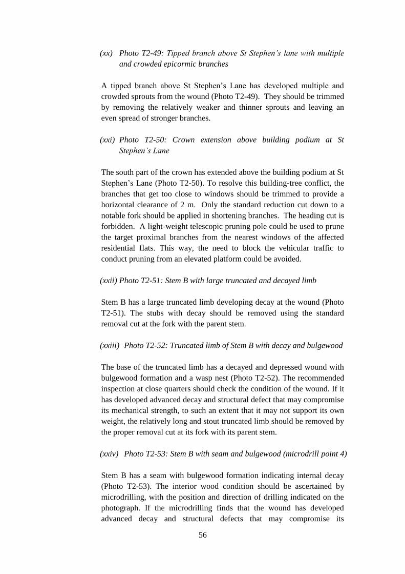
56
(xx) Photo T2-49: Tipped branch above St Stephen’s lane with multiple
and crowded epicormic branches
A tipped branch above St Stephen’s Lane has developed multiple and
crowded sprouts from the wound (Photo T2-49). They should be trimmed
by removing the relatively weaker and thinner sprouts and leaving an
even spread of stronger branches.
(xxi) Photo T2-50: Crown extension above building podium at St
Stephen’s Lane
The south part of the crown has extended above the building podium at St
Stephen’s Lane (Photo T2-50). To resolve this building-tree conflict, the
branches that get too close to windows should be trimmed to provide a
horizontal clearance of 2 m. Only the standard reduction cut down to a
notable fork should be applied in shortening branches. The heading cut is
forbidden. A light-weight telescopic pruning pole could be used to prune
the target proximal branches from the nearest windows of the affected
residential flats. This way, the need to block the vehicular traffic to
conduct pruning from an elevated platform could be avoided.
(xxii) Photo T2-51: Stem B with large truncated and decayed limb
Stem B has a large truncated limb developing decay at the wound (Photo
T2-51). The stubs with decay should be removed using the standard
removal cut at the fork with the parent stem.
(xxiii) Photo T2-52: Truncated limb of Stem B with decay and bulgewood
The base of the truncated limb has a decayed and depressed wound with
bulgewood formation and a wasp nest (Photo T2-52). The recommended
inspection at close quarters should check the condition of the wound. If it
has developed advanced decay and structural defect that may compromise
its mechanical strength, to such an extent that it may not support its own
weight, the relatively long and stout truncated limb should be removed by
the proper removal cut at its fork with its parent stem.
(xxiv) Photo T2-53: Stem B with seam and bulgewood (microdrill point 4)
Stem B has a seam with bulgewood formation indicating internal decay
(Photo T2-53). The interior wood condition should be ascertained by
microdrilling, with the position and direction of drilling indicated on the
photograph. If the microdrilling finds that the wound has developed
advanced decay and structural defects that may compromise its

57
mechanical strength to such an extent that it may not support its load, the
weight of the branches supported by the stem should be trimmed. The
amount to be removed should be contingent upon the condition and
quantity of the remaining sound wood.
The microdrilling graph (Appendix Figure T2-P4) indicates that the drill
bit stop at 40 cm without exiting the stem, because it was too short to
penetrate the entire stem diameter. A microdrill with a longer drill bit or
an additional drilling entering the stem from the opposite direction could
have overcome this inherent instrumental constraint. Thus the results
provided by the contractor show only a partial picture of the internal
wood condition at this site of potential weakness. Based on the detected
portion of the stem, weakened wood due to decay is found from 16 cm to
21.5 cm. There is enough sound wood on the two sides to provide support.
The decay may continue to deteriorate to a more advanced stage and may
spread to affect more wood. This position of weakness needs to be
monitored continually in future inspections.
(xxv) Photo T2-54: Stem B with limb-loss wound and decay
At the lower part of stems B, a limb-loss wound is beset by decay and has
developed some sprouts (Photo T2-54). As callus tissues have formed
around the edge, the wound should be monitored for signs of continued
decay.
(xxvi) Photo T2-55: Stem B branch with open decayed wound (microdrill
point 5)
A decayed wound with incomplete callus formation is found on a wavy
branch of stem B. The internal condition of wood should be explored
using microdrilling with the arrow denoting the drilling position and
orientation (Photo T2-55). The load on the defective branch should be
reduced in proportion to the amount of remaining sound wood.
The drill bit went through the branch at point 5 (Appendix Figure T2-P5),
indicating a stem diameter of about 21.6 cm. No notable pocket of
advanced decay, cavity or crack has been detected along the drill path.
The decay at the open wound has not penetrated into the interior of the
stem. The results do not call for drastic pruning or end-load reduction
treatment.

58
(xxvii) Photo T2-56: Stem A1 with decayed stub (microdrill point 6)
Stem A1 has a decayed stub with bulgewood formation and wasp nest
(Photo T2-56). The interior wood condition should be ascertained by
microdrilling, with the position and direction of drilling indicated on the
photograph. If the microdrilling finds that the wound has developed
advanced decay and structural defect that may compromise its mechanical
strength to such an extent that it may not support its load, the weight of
the branches supported by the stem should be trimmed. The amount to be
removed should be contingent upon the condition and quantity of the
remaining sound wood. The stub-end wound with jagged edges or an
uneven surface should be very carefully trimmed using a sharp arborist
manual saw and with the help of a carpenter's chisel.
The drilling results are presented in Appendix Figure T2-P6. The wood
from about 9 cm to 17.5 cm has been degraded by decay which is likely
to have spread from the decayed stub shown in Photo T2-56. The decay
has not reached the advanced stage at this juncture, and together with the
development of response wood as expressed by the bulgewood on both
sides of the wound, there should be enough wound wood to hold the stem.
It is possible that the decay may progress in due course to the more
advanced stage and spread to a larger proportion of the stem. This
potential weakness should be continually monitored both visually and
with the help of instruments.
(xxviii) Photo T2-57: Stem A1 with depressed and decayed wounds and
bulgewood (microdrill points 7 and 8)
The south side of stem A1 has two decayed and depressed wounds with
wasp nests (Photo T2-57). The internal condition of the wood should be
ascertained by two microdrillings, with the positions and directions of
drillings annotated on the photograph. If the microdrilling finds that the
wound has developed advanced decay and structural defect that may
compromise its mechanical strength to such an extent that it may not
support its load, the weight of the branches supported by the stem should
be trimmed. The amount to be removed should be contingent upon the
condition and quantity of the remaining sound wood.
The microdrilling trace shown in Appendix Figure T2-P7 has not drilled
through the stem. It stopped inexplicably at 24 cm whereas the stem
diameter should be around 40 cm. It is possible that the drilling
erroneously followed an off-centre path, hence a shorter trace was
recorded. Thus the drilling graph has detected only a part of the stem
interior condition. Based on the part that has been drilled, the wood

59
condition does not demonstrate advanced decay, cavity or other structural
weakness, hence drastic pruning to reduce loading on the stem is not
warranted.
The microdrilling trace shown in Appendix Figure T2-P8 has gone
through the stem. It indicates two pockets of decay which have a limited
extent each of about 2 cm diameter. The decay at the open wound has
penetrated into the interior part of the stem, although the spread at the
present stage is limited. There is enough sound wood to support the stem.
As a precautionary measure, about 10% of the end load should be
trimmed. The pruning should selectively remove the thinner and weaker
branches with a view to leaving an even spread of remaining branches.
The weak point should be continually monitored to check whether it will
further aggravate to a more risky stage.
(xxix) Photo T2-58: Stem C large decayed wound of truncated limb
A large wound with decay is found at the lower part of stem C, left by the
truncation of a thick limb (Photo T2-58). The wound should be monitored
for signs of continued decay.
(xxx) Photo T2-59: Stem C with decayed and recessed wound
The lower part of stem C has a decayed wound in a recessed niche (Photo
T2-59). It could be very carefully trimmed with the help of a carpenter's
chisel.
(xxxi) Photo T2-60: Stem C with trapped rubbish
A piece of plastic rubbish is partly engulfed and trapped by wood growth
in Stem C (Photo T2-60). It should be pulled out manually, if it is
possible to do so. Refrain from using tools or excessive force in the
extraction process.
(xxxii) Photo T2-61: Stem C with cracks, decayed wound and crotch
(microdrill points 9 and 10)
The middle section of Stem C has developed cracks, seam, bulgewood,
decayed wound, and a decayed crotch (Photo T2-61). The adjacent branch
removal wound has developed decay. The internal condition of the wood
should be ascertained by two microdrillings, with the positions and
directions of drillings annotated on the photograph. The load on the
defective branch should be reduced in proportion to the amount of
remaining sound wood and the condition of the structural defect.

60
Microdrilling at point 9 (Appendix Figure T2-P9) shows a cavity of about
4.5 cm diameter. The t/r ratio at the thinner side of the wood shell is
11/17.5 = 0.63 which is above the critical threshold of 0.33. The almost
vertical edges on both sides of the trough imply that the “cavity” could be
a gap between the stem and a lignified aerial root. At point 10, drilling
was made through the crotch with surficial decay symptoms (Appendix
Figure T2-P10). The wood from 0 cm to 6 cm has been partly degraded
by decay. The remaining wood is generally sound and has the strength
and thickness to hold the stem. Overall, the stem does not require drastic
load reduction.
(xxxiii) Photo T2-62: Stem C branch with bulgewood
The bulgewood developed in a branch of Stem C indicates possible
internal decay (Photo T2-62). The load on the defective branch should be
reduced in proportion to the amount of remaining sound wood and the
condition of the structural defect.
(xxxiv) Photo T2-63: Stem C branch stub with decay
The decay of the stub on a branch of stem C may extend into the parent
branch (Photo T2-63). The stub should be removed using the standard
removal cut at the fork with the parent stem.
(xxxv) Photo T2-64: Stem C tipped branch with decay spread
The tipped branch of stem C is beset by the spread of decay from the
wound and dead sprouts (Photo T2-64). The dead branch should be
removed using the standard removal cut at the fork with the parent stem.
(xxxvi) Photo T2-65: Stem C branch with crack at crotch
A branch of stem C has developed a crack at the critical crotch position
(Photo T2-65). The crack should be assessed at close quarters to find out
its length and depth and whether internal decay has developed. The result
will determine the amount of wood to be removed from the affected
branch. In the extreme case, the entire branch should be removed along
the dotted line.

61
3.1.4 Assessment of T3 and arboricultural recommendations
(a) Overall tree structure and condition
(i) Tree-wall relationship
T3 is one of the four stonewall trees dwelling on the eastern one-third of
the subject wall (Photo T3-1). It is situated near the staircase linking
Bonham Road to St Stephen’s Lane. Due to close spacing amongst the
row of trees, their crown spread tends to be laterally restricted by mutual
interference (Photo T3-2). The semi-mature tree perches on the crest of
the wall and hangs above the bus stop at Bonham Road (Photo T3-3). It
leans towards Bonham Road by about 40 degree at the base, but assumes a
more upright posture in the remainder of the trunk which tilts at 8 degree
from the vertical.
(ii) Tree dimensions and biomass structure
The tree measures 14.77 m tall. Some large branches have been tipped
(Photo T3-4). Three rather thick trunks with DBH respectively at A=30
cm, B=56 cm and C=74 cm support the confined and reduced crown
(Photos T3-5 and T3-6). The aggregate DBH reaches 100 cm. Trunk A
that tilts heavily towards T4 at its east side has been truncated, and it does
not carry any branches. Trunk C has been truncated at a low level and
carries no branches. It is connected to trunk B via a bundle of lignified
aerial roots. Trunk C’s main residual function is lending support to the
limbs and branches of trunk B.
(iii) Trunk B and low branch removal
Trunk B is the only one that has been left largely intact (Photo T3-5). The
tree’s crown is built mainly by branches attached to trunk B. However, a
notable number of limbs and branches formerly attached to trunk B have
been lost. The tree suffers from excessive removal or loss of its lower
branches. This defect could suppress the tree’s ability to develop a proper
trunk taper to compromise its mechanical strength at the critical trunk
base level (cf. Section 4.2.4).
(iv) Tree hazard rating
Tree hazard assessment has a score of 5 which is rated as low (Table 3G).
The main contribution to tree risk is the breakage of branches that are
structurally weak or decayed.

62
(b) Assessment of surface roots and interface with the stone wall
(i) Wall structure and surface root spread
The stone wall at T3 stands 3.27 m above the ground. Similar to the
condition at T2, the masonry blocks are larger in the lower two-third of the
wall, and smaller in the top one-third (Photo T3-7). Root spread on the
wall face is somewhat limited laterally and especially vertically. The
surface roots are confined mainly to the upper half of the wall. The more
or less straight and horizontal lower edge of the surface root mass indicates
that the lower half was cut away. Some roots on the east side have
intertwined with those of its neighbour T4, with some grafting of the two
root systems.
(ii) Root growth at wall toe and trunk base
A U-channel with concrete covers is present at the wall base (Photo T3-7).
The excavation associated with its installation would have removed some
of the surface roots at the lower half of the wall and roots that have grown
into the soil under the pavement. The trunk base is sitting near the wall top
(Photos T3-8, T3-9 and T3-10). Most of the tension roots that hold the tree
against overturning and take water and nutrients from the aft-soil are
believed to be situated underneath and in the vicinity of the trunk base.
(iii) Shift of masonry block
Just above the trunk base, a masonry block has been pushed away from the
wall face (Photo T3-10). At the wall top, the interlocking force that applies
a strong force against displacement is relatively weak. The shifting of one
piece of stone probably indicates the localized pressure exerted by root
growth.
(iv) Removing rubbish from surface roots
Measures can be implemented to improve the root growth conditions of
the tree. The rubbish that has deposited on the surface roots and the trunk
bases and crotches, together with the leaf litter, should be regularly
removed with the help of a brush to avoid moisture accumulation which
could induce decay (Photo T3-10). More importantly, keeping the gap
clean can avoid the potentially risky wedging effect which may destabilize
the tree (cf. Section 4.2.3).
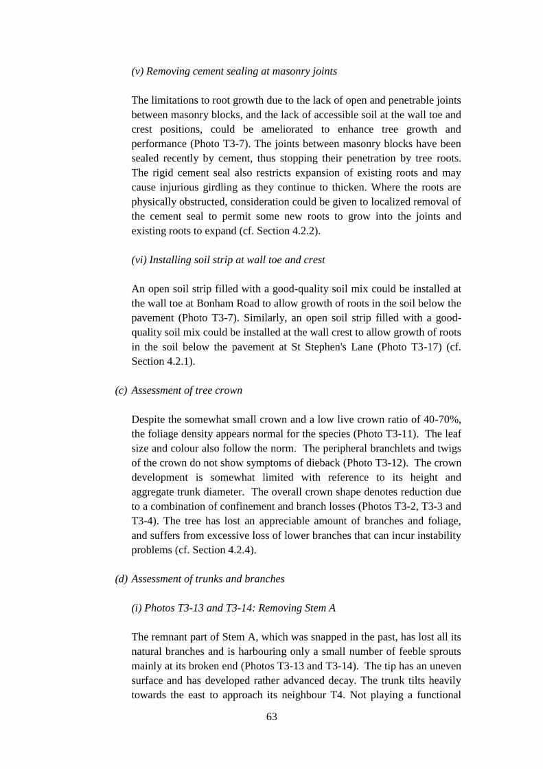
63
(v) Removing cement sealing at masonry joints
The limitations to root growth due to the lack of open and penetrable joints
between masonry blocks, and the lack of accessible soil at the wall toe and
crest positions, could be ameliorated to enhance tree growth and
performance (Photo T3-7). The joints between masonry blocks have been
sealed recently by cement, thus stopping their penetration by tree roots.
The rigid cement seal also restricts expansion of existing roots and may
cause injurious girdling as they continue to thicken. Where the roots are
physically obstructed, consideration could be given to localized removal of
the cement seal to permit some new roots to grow into the joints and
existing roots to expand (cf. Section 4.2.2).
(vi) Installing soil strip at wall toe and crest
An open soil strip filled with a good-quality soil mix could be installed at
the wall toe at Bonham Road to allow growth of roots in the soil below the
pavement (Photo T3-7). Similarly, an open soil strip filled with a good-
quality soil mix could be installed at the wall crest to allow growth of roots
in the soil below the pavement at St Stephen's Lane (Photo T3-17) (cf.
Section 4.2.1).
(c) Assessment of tree crown
Despite the somewhat small crown and a low live crown ratio of 40-70%,
the foliage density appears normal for the species (Photo T3-11). The leaf
size and colour also follow the norm. The peripheral branchlets and twigs
of the crown do not show symptoms of dieback (Photo T3-12). The crown
development is somewhat limited with reference to its height and
aggregate trunk diameter. The overall crown shape denotes reduction due
to a combination of confinement and branch losses (Photos T3-2, T3-3 and
T3-4). The tree has lost an appreciable amount of branches and foliage,
and suffers from excessive loss of lower branches that can incur instability
problems (cf. Section 4.2.4).
(d) Assessment of trunks and branches
(i) Photos T3-13 and T3-14: Removing Stem A
The remnant part of Stem A, which was snapped in the past, has lost all its
natural branches and is harbouring only a small number of feeble sprouts
mainly at its broken end (Photos T3-13 and T3-14). The tip has an uneven
surface and has developed rather advanced decay. The trunk tilts heavily
towards the east to approach its neighbour T4. Not playing a functional

64
role in the overall scheme of the tree, trunk A is recommended for removal
by cutting at its base, taking care to minimize injury of adjacent trunk B
and associated lignified aerial roots.
(ii) Photos T3-15: Trimming Stem B limb-removal wound
The wounds left by limb removal from stem B have developed decay and
cavity (Photo T3-15). Their jagged edges or uneven surfaces or decayed
wood should be very carefully trimmed using a sharp arborist manual saw
with the help of a carpenter’s chisel. However, the well-formed callus
tissues should as far as practicable be left undisturbed.
(iii) Photos T3-16: Upward curving limb of Stem B
A low, upward-curving and truncated limb of stem B supports two long
ascending epicormic branches (Photo T3-16). For the one on the right-
hand side, evaluation of the cut wound at close quarters should inform
whether the decayed tip of the parent branch has sufficient sound wood to
hold the epicormic branch. If not, the daughter branch should be shortened
by a reduction cut. The amount to be removed shall correspond to the
condition of the wood around the cut face.
(iii) Photo T3-17: Long epicormic branch with elbow joint of Stem B
A long epicormic branch emerges with an elbow joint from a branch-cut
wound (Photo T3-17). Evaluation of the cut face at close quarters should
inform whether the decayed tip of the parent branch has sufficient sound
wood to hold the epicormic branch. If not, the daughter branch should be
shortened by a reduction cut. The amount to be removed shall correspond
to the condition of the wood around the cut face.
(iv) Photo T3-18:Tipped branch with long epicormic branch of Stem B
A top branch of stem B was tipped and has developed a series of long and
nearly parallel replacement epicormic branches (Photo T3-18). The
crowded branching habit could be partly relieved by removing one of the
three parallel branches. Evaluation a close quarters should inform whether
the decayed tip of the parent branch has sufficient sound wood to hold the
epicormic branches. If not, the daughter branches should be shortened by
reduction cut. The amount to be removed shall correspond to the condition
of the wood around the cut face.

65
(v) Photo T3-19: Decayed stubs on Stem B
Decayed wounds are found at the stubs of truncated branches at stem B
(Photo T3-19). The decay could spread to the parent stem. The stub with
advanced decay should be removed using the standard removal cut at the
fork with the parent stem.
(vi) Photo T3-20: Stub with advanced decay on Stem C
The truncated stem C has developed advanced decay at the large wound
(Photo T3-20). The terminal end of the stump with advanced decay should
be cut away, but the lignified aerial root linking stem C to stem B above
should not be cut.
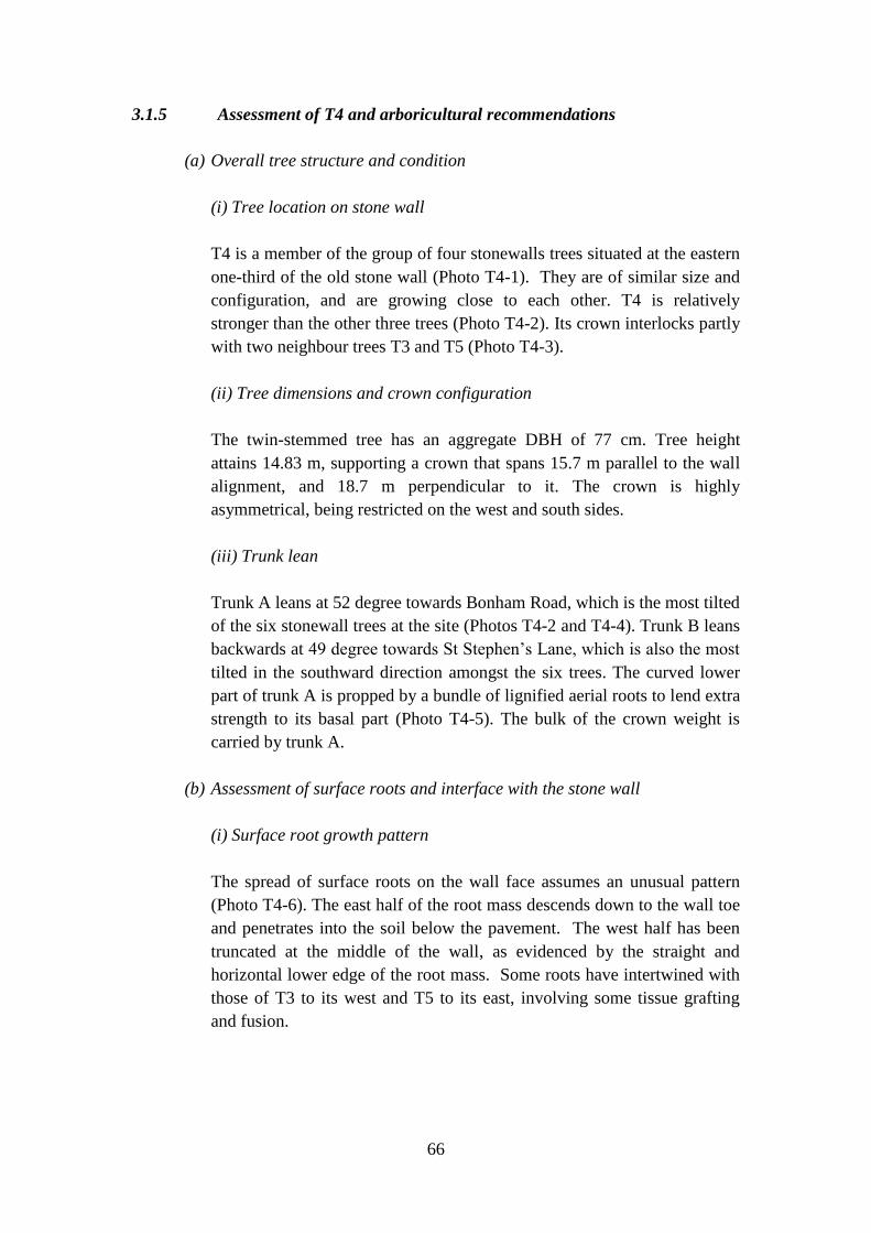
66
3.1.5 Assessment of T4 and arboricultural recommendations
(a) Overall tree structure and condition
(i) Tree location on stone wall
T4 is a member of the group of four stonewalls trees situated at the eastern
one-third of the old stone wall (Photo T4-1). They are of similar size and
configuration, and are growing close to each other. T4 is relatively
stronger than the other three trees (Photo T4-2). Its crown interlocks partly
with two neighbour trees T3 and T5 (Photo T4-3).
(ii) Tree dimensions and crown configuration
The twin-stemmed tree has an aggregate DBH of 77 cm. Tree height
attains 14.83 m, supporting a crown that spans 15.7 m parallel to the wall
alignment, and 18.7 m perpendicular to it. The crown is highly
asymmetrical, being restricted on the west and south sides.
(iii) Trunk lean
Trunk A leans at 52 degree towards Bonham Road, which is the most tilted
of the six stonewall trees at the site (Photos T4-2 and T4-4). Trunk B leans
backwards at 49 degree towards St Stephen’s Lane, which is also the most
tilted in the southward direction amongst the six trees. The curved lower
part of trunk A is propped by a bundle of lignified aerial roots to lend extra
strength to its basal part (Photo T4-5). The bulk of the crown weight is
carried by trunk A.
(b) Assessment of surface roots and interface with the stone wall
(i) Surface root growth pattern
The spread of surface roots on the wall face assumes an unusual pattern
(Photo T4-6). The east half of the root mass descends down to the wall toe
and penetrates into the soil below the pavement. The west half has been
truncated at the middle of the wall, as evidenced by the straight and
horizontal lower edge of the root mass. Some roots have intertwined with
those of T3 to its west and T5 to its east, involving some tissue grafting
and fusion.

67
(ii) Root growth at wall toe
The wall toe is equipped with a U-channel covered by concrete slabs
(Photos T4-6 and T4-7). The excavation necessary to install this drainage
channel would have severed or injured the roots that penetrated into soil
below the pavement. Some roots could grow below the channel to explore
the soil lying underneath and to capture more water and nutrients to
support tree growth.
(iii) Trunk base detachment from wall face
The trunk base is attached to the top part of the wall face (Photos T4-8 and
T4-9). A narrow gap is found between the wall face and the root mass,
indicating that the base of the tree has been detached somewhat from the
wall (Photos T4-8, T4-9, T4-10, T4-11 and T4-12). The tree anchorage
has failed to a certain extent by yielding a little. The remaining roots are
holding the tree against overturning and collapse.
(iv) Dense surface root mass
The dense network of surface roots to the east and west of the trunk base
embodies some roots that have turned backwards to move into the joints
and henceforth into the aft-soil. Together with the penetrated roots below
the trunk base, they afford critical tensional pull to hold the tree against
overturning (Photos T4-13 and T4-14). The two obsolete iron angle bars
situated near the trunk base could be removed. If their removal may harm
the surface roots, the exposed part could be sawn away without extracting
the embedded part.
(v) Root growth restriction
The limitations to root growth due to the lack of open and penetrable joints
between masonry blocks, and the lack of accessible soil at the wall toe and
crest positions, could be ameliorated to enhance tree growth and
performance.
(vi) Removing cement seal at masonry joints
The joints between masonry blocks have been sealed recently by cement,
thus stopping their penetration by tree roots. The rigid cement seal also
restricts expansion of existing roots and may cause girdling injury as they
continue to thicken. Where the roots are physically obstructed,
consideration could be given to localized removal of the cement seal to

68
permit some new roots to grow into the joints and existing roots to expand
(cf. Section 4.2.2).
(vii) Installing soil strip at wall toe
An open soil strip filled with a good-quality soil mix could be installed at
the wall toe at Bonham Road, in lieu of the existing drainage u-channel, to
allow growth of roots in the soil below the pavement (cf. Section 4.2.1). If
the propping method C explained in Section 3.15e is adopted to support
the tree at the Bonham Road pavement, the design could be adjusted to
accommodate both the propping frame and the soil strip.
(viii) Installing soil strip at wall crest
An open soil strip filled with a good-quality soil mix could be installed at
the wall crest to allow growth of roots in the soil below the pavement at St
Stephen's Lane. A segment of the existing stone parapet wall will have to
be replaced by railing to permit the roots to reach this new soil strip (cf.
Section 4.2.1). If the cable bracing method B to pull the tree at the
northern edge of St Stephen's Lane explained in Section 3.15e is adopted,
the design could be adjusted to accommodate both the steel frame and the
soil strip.
(c) Assessment of tree crown
(i) Two subcrowns supported by trunks A and B
The crown of T4 is composed of two portions supported respectively by
trunk A and trunk B. The bulk of the crown supported by trunk A hangs
above Bonham Road (subcrown A), and similarly the bulk of the crown
supported by trunk B hangs above St Stephen’s Lane (subcrown B)
(Photos T4-15 and T4-1). Subcrown A was subject to tipping in the past,
and it has since rebuilt its lost top by an expanded epicormic branch (Photo
T4-15). Subcrown A is notably larger and heavier than B.
(ii) Crown configuration and condition
The live crown ratio of the somewhat enfeebled tree stands at a medium
level of 40-70%. Foliage density is rated as sparse due to compromised
vigour, but the leaf size and colour are judged as normal. Dieback of twigs
is gauged as low at < 5%. The crown is not symmetrical, and some main
branches have been tipped. Excessive loss of lower branches is obvious,
which carries the undesirable consequence of failing to develop proper

69
trunk taper to compromise tree stability (cf. Section 4.2.4). Overall tree
vigour is judged to be average.
(d) Assessment of trunks and branches
(i) Overall condition (microdrill points 1 and 2)
The truncated tip of Stem A is shouldering the heavy load of a large
replacement epicormic branch (Photo T4-15). The evaluation at close
quarters should inform whether the tip of the parent branch has sufficient
sound wood to hold the rather heavy epicormic replacement branch. If not,
the end weight of the daughter branch should be reduced by removing
some of the smaller and weaker branches. The amount to be removed shall
be commensurate with the condition of the wood around the cut face.
Two microdrillings were made by the contractor through Stems A and B
respectively (Photo T4-5). Both drillings do not penetrate the whole trunk;
they stop at 40 cm which is the length of the rather short drill bit. Thus the
results cannot detect the internal wood condition of the whole trunk
section. Based on the limited data, Stem A has sound wood (Appendix
Figure T4-P1). Stem B displays lowered strength in 0-17 cm, denoting the
presence of decay or weak wood in the lignified aerial roots attached to the
trunk (Appendix Figure T4-P2). The limited data show that the main trunk
has enough sound wood. No drastic pruning is necessary at this stage. As
the decay may progress in due course to a more advanced stage and spread
to a large volume of wood, the structurally compromised location should
be continually monitored.
(ii) Photo T4-16: Tipped branch of Stem A with epicormic branch and
elbow joint
A tipped branch of Stem A carries a replacement epicormic branch with an
elbow joint (Photo T4-16). The evaluation at close quarters should tell
whether the tip of the parent branch has sufficient sound wood to hold the
rather heavy epicormic replacement branch. If not, the end weight of the
daughter branch should be reduced by removing some of the small
branches. The amount to be removed shall be commensurate with the
condition of the wood around the cut face.
(iii) Photo T4-17: Hanging rubbish trapped in crown
Hanging plastic rubbish is trapped in the crown (Photo T4-17). It should
be carefully extricated and removed in the course of pruning with the help
of a hydraulic platform.
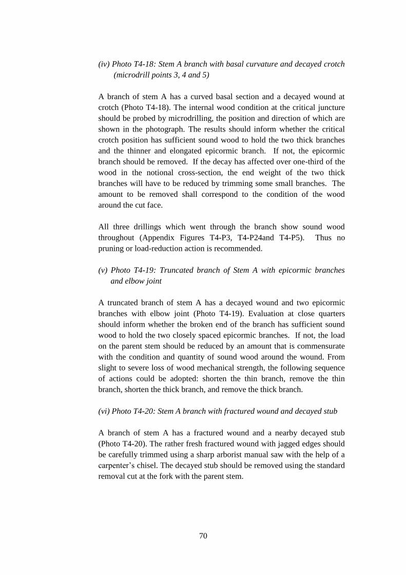
70
(iv) Photo T4-18: Stem A branch with basal curvature and decayed crotch
(microdrill points 3, 4 and 5)
A branch of stem A has a curved basal section and a decayed wound at
crotch (Photo T4-18). The internal wood condition at the critical juncture
should be probed by microdrilling, the position and direction of which are
shown in the photograph. The results should inform whether the critical
crotch position has sufficient sound wood to hold the two thick branches
and the thinner and elongated epicormic branch. If not, the epicormic
branch should be removed. If the decay has affected over one-third of the
wood in the notional cross-section, the end weight of the two thick
branches will have to be reduced by trimming some small branches. The
amount to be removed shall correspond to the condition of the wood
around the cut face.
All three drillings which went through the branch show sound wood
throughout (Appendix Figures T4-P3, T4-P24and T4-P5). Thus no
pruning or load-reduction action is recommended.
(v) Photo T4-19: Truncated branch of Stem A with epicormic branches
and elbow joint
A truncated branch of stem A has a decayed wound and two epicormic
branches with elbow joint (Photo T4-19). Evaluation at close quarters
should inform whether the broken end of the branch has sufficient sound
wood to hold the two closely spaced epicormic branches. If not, the load
on the parent stem should be reduced by an amount that is commensurate
with the condition and quantity of sound wood around the wound. From
slight to severe loss of wood mechanical strength, the following sequence
of actions could be adopted: shorten the thin branch, remove the thin
branch, shorten the thick branch, and remove the thick branch.
(vi) Photo T4-20: Stem A branch with fractured wound and decayed stub
A branch of stem A has a fractured wound and a nearby decayed stub
(Photo T4-20). The rather fresh fractured wound with jagged edges should
be carefully trimmed using a sharp arborist manual saw with the help of a
carpenter’s chisel. The decayed stub should be removed using the standard
removal cut at the fork with the parent stem.
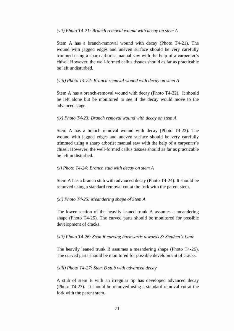
71
(vii) Photo T4-21: Branch removal wound with decay on stem A
Stem A has a branch-removal wound with decay (Photo T4-21). The
wound with jagged edges and uneven surface should be very carefully
trimmed using a sharp arborist manual saw with the help of a carpenter’s
chisel. However, the well-formed callus tissues should as far as practicable
be left undisturbed.
(viii) Photo T4-22: Branch removal wound with decay on stem A
Stem A has a branch-removal wound with decay (Photo T4-22). It should
be left alone but be monitored to see if the decay would move to the
advanced stage.
(ix) Photo T4-23: Branch removal wound with decay on stem A
Stem A has a branch removal wound with decay (Photo T4-23). The
wound with jagged edges and uneven surface should be very carefully
trimmed using a sharp arborist manual saw with the help of a carpenter’s
chisel. However, the well-formed callus tissues should as far as practicable
be left undisturbed.
(x) Photo T4-24: Branch stub with decay on stem A
Stem A has a branch stub with advanced decay (Photo T4-24). It should be
removed using a standard removal cut at the fork with the parent stem.
(xi) Photo T4-25: Meandering shape of Stem A
The lower section of the heavily leaned trunk A assumes a meandering
shape (Photo T4-25). The curved parts should be monitored for possible
development of cracks.
(xii) Photo T4-26: Stem B curving backwards towards St Stephen’s Lane
The heavily leaned trunk B assumes a meandering shape (Photo T4-26).
The curved parts should be monitored for possible development of cracks.
(xiii) Photo T4-27: Stem B stub with advanced decay
A stub of stem B with an irregular tip has developed advanced decay
(Photo T4-27). It should be removed using a standard removal cut at the
fork with the parent stem.

72
(xiv) Photo T4-28: Stem B stub with decay
A branch stub of stem B has developed decay (Photo T4-28). It should be
removed using a standard removal cut at the fork with the parent stem.
(xv) Photo T4-28: Existing Cobra bracing using Stem B to hold Stem A
An existing Cobra cable bracing has been installed using Stem B which
points backwards towards St Stephen’s Lane to hold Stem A that leans and
hangs above Bonham Road. Stem B may not have the strength to provide
support to Stem A. Please see the alternative support systems explained
below (Section 3.1.5e).
(xvi) Prevention of wedging effect and decay at trunk base
The rubbish that has deposited on the surface roots and the adjacent trunk
base, together with the leaf litter, should be regularly removed with the
help of a brush to avoid moisture accumulation which could induce decay
at the critical trunk base position (Photos T4-11 and T4-12). More
importantly, objects trapped in the wedge gap caused by the detachment of
the tree from the wall could aggravate the detachment process due to the
wedging effect. They must be diligently and thoroughly removed from the
gap to prevent aggravation of the detachment risk (cf. Section 4.2.3).
(e) Proposal for tree support systems for T4
(i) Tree hazard status
Tree hazard assessment has a score of 9 plus an extra score due to
detachment of the trunk base from the wall face. The total hazard score of
10 has pushed the tree from top of the medium risk category into the base
of the high risk category (Table 4G). Of the six stonewall trees at the site,
T4 has been accorded the highest hazard score. The tensional roots that
should pull the tree against overturning have yielded a little to create a gap
between the tree base and the wall face (Photos T4-8, T4-9, T4-10, T4-11
and T4-12). The main contribution to tree risk is the potential for the
whole tree to be uprooted from the wall. If the tree were to fail, it is likely
that the whole tree will collapse on Bonham Road.
(ii) Three tailor-made tree support systems
It is pertinent to provide artificial, effective and long-lasting support to the
tree at the earliest opportunity to prevent tree failure. Due to the severe
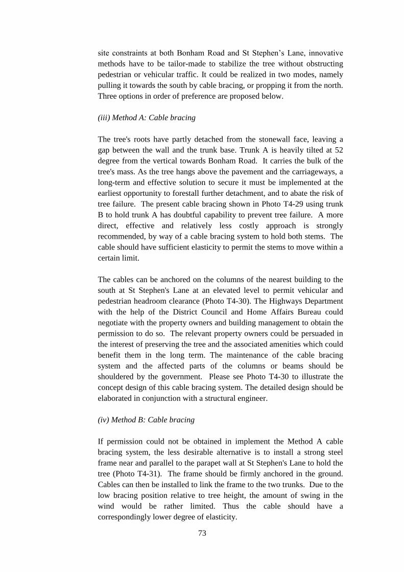
73
site constraints at both Bonham Road and St Stephen’s Lane, innovative
methods have to be tailor-made to stabilize the tree without obstructing
pedestrian or vehicular traffic. It could be realized in two modes, namely
pulling it towards the south by cable bracing, or propping it from the north.
Three options in order of preference are proposed below.
(iii) Method A: Cable bracing
The tree's roots have partly detached from the stonewall face, leaving a
gap between the wall and the trunk base. Trunk A is heavily tilted at 52
degree from the vertical towards Bonham Road. It carries the bulk of the
tree's mass. As the tree hangs above the pavement and the carriageways, a
long-term and effective solution to secure it must be implemented at the
earliest opportunity to forestall further detachment, and to abate the risk of
tree failure. The present cable bracing shown in Photo T4-29 using trunk
B to hold trunk A has doubtful capability to prevent tree failure. A more
direct, effective and relatively less costly approach is strongly
recommended, by way of a cable bracing system to hold both stems. The
cable should have sufficient elasticity to permit the stems to move within a
certain limit.
The cables can be anchored on the columns of the nearest building to the
south at St Stephen's Lane at an elevated level to permit vehicular and
pedestrian headroom clearance (Photo T4-30). The Highways Department
with the help of the District Council and Home Affairs Bureau could
negotiate with the property owners and building management to obtain the
permission to do so. The relevant property owners could be persuaded in
the interest of preserving the tree and the associated amenities which could
benefit them in the long term. The maintenance of the cable bracing
system and the affected parts of the columns or beams should be
shouldered by the government. Please see Photo T4-30 to illustrate the
concept design of this cable bracing system. The detailed design should be
elaborated in conjunction with a structural engineer.
(iv) Method B: Cable bracing
If permission could not be obtained in implement the Method A cable
bracing system, the less desirable alternative is to install a strong steel
frame near and parallel to the parapet wall at St Stephen's Lane to hold the
tree (Photo T4-31). The frame should be firmly anchored in the ground.
Cables can then be installed to link the frame to the two trunks. Due to the
low bracing position relative to tree height, the amount of swing in the
wind would be rather limited. Thus the cable should have a
correspondingly lower degree of elasticity.

74
As the Lane is used for vehicular access, the steel frame has to be
positioned as near as possible to the parapet wall to maintain sufficient
vehicular lateral clearance. It implies that excavation will have to be
conducted near the tree which may harm the roots that have penetrated the
soil lying below the Lane. To minimize this impact, the positions of the
two anchors for the frame could be placed respectively between T4 and T3,
and T4 and T5. Moreover, the impact could also be reduced by developing
a technique with the help of an engineer to install the anchors with a
minimum excavation limit. Please see the Photo T4-31 which illustrates
the concept design of this alternative cable bracing system. The detailed
design should be elaborated in conjunction with a structural engineer.
(v) Method C: Propping
The two cable bracing methods explained above are preferred to stabilize
the tree and to abate the tree failure hazard. Propping the tree in front of
the stone wall is inordinately difficult due to the narrow pavement and its
use also as a bus stop. If both cable bracing methods cannot be
implemented, the least desirable propping option will have to be enlisted.
In view of the severe site constraints, this option has to be considered as a
compromise that is less effective in holding the tree. A strong steel frame
will have to be constructed at the pavement near the wall face to minimize
disturbance to pedestrian flow and to reduce risk to buses and other
vehicles getting too close to the frame (Photo T4-32). To leave sufficient
wide berth for pedestrian flow, the frame below the normal pedestrian
vertical clearance will have to abut onto the wall face.
The vertical support column has to be firmly anchored in the ground and
the wall to hold the load of the tree and to prevent overturning. A strong
cantilever arm will extend from the top of the frame to bear the weight of
the tree. The interface between the arm and the trunk should be properly
cushioned to prevent bruising injuries. The exact positions of the anchors
should be carefully chosen to minimize impacts on surface and penetrated
roots. To avoid injuries to the tree, great care in conjunction with physical
protection and other precautionary measures should be adopted in
installing the steel frame. Please see Photo T4-32 which illustrates the
concept design of the proposed propping system. The detailed design
should be elaborated in conjunction with a structural engineer.
(vi) Method D: Short-term contingency measure to abate tree risk
Three long-term options in order of preference have been proposed in the
above sections to abate the risk of T4 on targets. It is envisaged that one
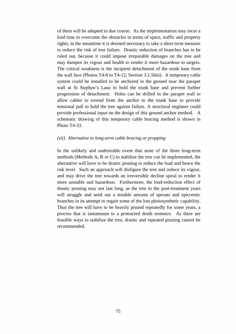
75
of them will be adopted in due course. As the implementation may incur a
lead time to overcome the obstacles in terms of space, traffic and property
rights, in the meantime it is deemed necessary to take a short-term measure
to reduce the risk of tree failure. Drastic reduction of branches has to be
ruled out, because it could impose irreparable damages on the tree and
may dampen its vigour and health to render it more hazardous to targets.
The critical weakness is the incipient detachment of the trunk base from
the wall face (Photos T4-8 to T4-12; Section 3.1.5biii). A temporary cable
system could be installed to be anchored in the ground near the parapet
wall at St Stephen’s Lane to hold the trunk base and prevent further
progression of detachment. Holes can be drilled in the parapet wall to
allow cables to extend from the anchor to the trunk base to provide
tensional pull to hold the tree against failure. A structural engineer could
provide professional input on the design of this ground anchor method. A
schematic drawing of this temporary cable bracing method is shown in
Photo T4-33.
(vii) Alternative to long-term cable bracing or propping
In the unlikely and undesirable event that none of the three long-term
methods (Methods A, B or C) to stabilize the tree can be implemented, the
alternative will have to be drastic pruning to reduce the load and hence the
risk level. Such an approach will disfigure the tree and reduce its vigour,
and may drive the tree towards an irreversible decline spiral to render it
more unstable and hazardous. Furthermore, the load-reduction effect of
drastic pruning may not last long, as the tree in the post-treatment years
will struggle and send out a notable amount of sprouts and epicormic
branches in its attempt to regain some of the lost photosynthetic capability.
Thus the tree will have to be heavily pruned repeatedly for some years, a
process that is tantamount to a protracted death sentence. As there are
feasible ways to stabilize the tree, drastic and repeated pruning cannot be
recommended.

76
3.1.6 Assessment of T5 and arboricultural recommendations
(a) Overall tree structure and condition
(i) Tree location on stone wall
T5 is one of the four trees that are clustered at the eastern one-third of the
stone wall (Photo T5-1). It stands at 14.97 m tall, which is similar to its
three companions. The tree sits near the top of the wall. The height of the
first branch is elevated well above the ground at 5.18 m from the trunk
base. The tree leans towards Bonham Road at 21 degree.
(ii) Tree dimensions and biomass structure
Unlike its three stronger and multiple-stemmed partners, it has a single
trunk with DBH of 41 cm, which is rather slender in comparison with its
height (Photos T5-2 and T5-3). The height to DBH ratio of the trunk is as
high as 36.4, which signifies an inherently unstable shape. The crown is
also unusually narrow especially in the direction parallel to the wall
alignment at merely 9.3 m. Perpendicular to the wall, the crown is a little
wider at 11.9 m. Some branches interlock with its two neighbours, namely
T4 at its west and T8 at its east.
(b) Assessment of surface roots and interface with the stone wall
(i) Surface root distribution on wall face
The wall gets shorter towards the east end, and at T4 it is 2.54 m above the
pavement level (Photo T5-4). The surface roots extend from the trunk base
to the wall toe, with some penetration into the soil below the pavement.
One surface root in the middle of the root mass is particularly thick and it
lends important support to the trunk.
(ii) Interface between trunk base and wall face
The contact interface between the trunk base and the wall face is
somewhat limited in comparison with its partners on the same wall
segment (Photos T5-5 and T5-6). Organic litter and rubbish have
accumulated in the gap between the trunk base and the wall face (Photo
T5-7). They should be regularly removed to avoid the wedging effect and
wood decay (cf. Section 4.2.3).

77
(iii) Root growth restriction
The limitations to root growth due to the lack of open and penetrable joints
between masonry blocks, and the lack of accessible soil at the wall toe and
crest positions, could be ameliorated to enhance tree growth and
performance.
(iv) Removing cement sealing from masonry joints
The joints between masonry blocks have been sealed recently by cement,
thus stopping their penetration by tree roots. The rigid cement seal also
restricts expansion of existing roots and may cause girdling injury as they
continue to thicken. Where the roots are physically obstructed,
consideration could be given to localized removal of the cement seal to
permit some new roots to grow into the joints and existing roots to expand
(cf. Section 4.2.2).
(v) Installing soil strip at wall crest
An open soil strip filled with a good-quality soil mix could be installed at
the wall crest to allow growth of roots in the soil below the pavement at St
Stephen's Lane. A segment of the existing stone parapet wall will have to
be replaced by railing to permit the roots to reach this new soil strip (cf.
Section 4.2.1). If the cable bracing Method B explained in Section 3.1.6f
is adopted, the design could be adapted to accommodate both the steel
frame and the soil strip.
(vi) Installing soil strip at wall toe
An open soil strip filled with a good-quality soil mix could be installed at
the wall toe at Bonham Road, in lieu of the existing drainage U-channel
and pavement covered with unit pavers, to allow growth of roots in the soil
below the pavement (cf. Section 4.2.1). If the propping method C
explained in Section 3.16f is adopted to support the tree at the Bonham
Road pavement, the design could be adjusted to accommodate both the
propping frame and the soil strip.
(c) Assessment of large basal cavity
(i) Photos T5-8 and T5-9: Large cavity at trunk base with decay
As the large basal cavity is closely associated with root development and
hence compensatory reinforcement, the topic is discussed in this dedicated
section. It assumes a typical inverted V-shape of a basal cavity, and is

78
nearly as wide as the trunk base itself (Photos T5-8 and T5-9). The
internal surface of the cavity is covered with brownish decayed wood,
some of which has a loose consistence that can be removed with the hand.
The thickness of the residual wall around the cavity and especially the
amount of remaining sound wood should be ascertained by microdrilling.
Three drilling positions have been annotated on the photographs (Photos
T5-8 and T5-9). The results can inform the amount of sound wood in the
residual wall and whether it is adequate to support the tree’s biomass.
Field inspection indicates that the residual wall is rather thin.
The edges on both sides of the cavity has developed prominent strips of
response wood to compensate for the loss of wood strength due to cavity
formation at the critical position of the trunk (Photos T5-8 and T5-9). The
response wood tends to have a higher density, higher mechanical strength
and higher resistance to fungal decay. They contribute significantly to
reinforcing the trunk base against snapping failure. At the opposite side of
the trunk lean and at the basal position, the response wood affords critical
tensional pull. Moreover, the response wood development has extended
above the cavity to the lower-middle part of the trunk to offer notable ribs
of tension wood to pull and stabilize the leaning tree (Photo T5-10).
(ii) Photos T5-11 to T5-13: Trunk reinforcement by lignified aerial roots,
thickened root pro, and response wood
In addition to the reinforcement adjoining to the cavity, the tree has
developed two rather strong and upright lignified aerial root stands
adjacent to the trunk base (Photos T5-11 and T5-12). They provide
supplementary support to the tree at the critical load-bearing position, and
are instrumental in securing the tree against breakage at the hollowed trunk
base. The root stands have assumed a distinctive flattish shape
perpendicular to the wall face to maximize the tensional pull strength
against the overturning moment (Photo T5-13).
(d) Assessment of tree crown
(i) Narrow and confined crown development
The narrow crown has developed few branches (Photo T5-14). Two major
limbs follow a rather upright growth habit. One of the limbs displays
evidence of past tipping which has triggered the development of epicormic
branches from the wound. The two neighbour trees have literally
sandwiched and trapped the relatively weaker T5 in the intervening space.

79
The foliage density is rated as sparse, although leaf size and colour are
normal. Twig dieback is not evident, with less than 5%.
(ii) Competition with neighbour trees and loss of low branches
The tree has lost a good deal of its branches, and branch growth has been
confined by proximity and competition with neighbour trees which are
situated too close to it. The live crown ratio is put in the lowest category
of < 40%. Excessive loss of lower branches is noted, which can suppress
the tree’s ability to develop a proper trunk taper and compromise its
stability (cf. Section 4.2.4). Overall tree vigour can be reckoned as average.
(e) Assessment of trunks and branches
(i) Photos T5-8 and T5-9: Large cavity at trunk base with decay
(microdrill points 1, 2, 3 and 4)
The loose decayed wood in the large basal cavity could be cleaned to
reduce the chance of moisture accumulation and hence to dampen fungal
invasion of the remaining wood in the residual wall (Photos T5-8 and T5-
9). Only the badly decayed and partly detached wood in the large wound
should be very carefully removed. Do not attempt to excavate or remove
woody tissues that have not partially detached. Do not overdo this cleaning
exercise. The detached wood debris accumulated at the bottom of the
cavity should also be removed, if necessary with the help of a powerful
vacuum cleaner. The cavity cleaning could help to dampen fungal growth.
As a precautionary measure, a professional extermination company should
be enlisted to check thoroughly whether the tree has been infected by
termites. If so, the modern hormone bait method should forthwith be
applied to get rid of the wood consuming insects.
Two drillings penetrate the remaining wood shell of the large basal cavity.
At point 1, the shell thickness is merely 8 cm with somewhat degraded
wood (Appendix Figure T5-P1). Wood with advanced decay has been lost,
leaving the partly decayed wood in the shell. Lower down at point 2, some
wood with advanced decay still lingers on the cavity wall in 0-8 cm
beyond which the wood has indication of incipient decay (Appendix
Figure T5-P2). The wood shell measures 13 cm. As the cavity is open on
the south side, the t/r ratio is not applicable. The lignified aerial roots and
root props at and around the trunk base have reinforced it and compensate
for the loss of wood strength due to decay and cavity formation (Photos
T5-11 to T5-12). Moreover, the liberal development of response wood on

80
the upper side of the trunk base serves as pertinent tension wood
reinforcement to pull and help to stabilize the tilted tree (Photo T5-13).
Two more drillings were made above the basal cavity to explore whether
the decay has moved upwards into basal large cavity. A large internal
cavity of 15 cm diameter is found which signifies the longitudinal
extension of the decay column (Appendix Figure T5-P3). The cavity is
found on the west side, with a 33 cm residual wood shell of sound wood
concentrated on the east side. Further up at point 4 (Appendix Figure T5-
P4), the size of the internal cavity is smaller at 4 cm diameter and again
situated on the west side. Combining the results of points 3 and 4, the
decay column is notably constrained as it moves up the trunk. The
additional lignified roots and thickened root prop (Photo T5-11 to T5-13)
provide substitute support above point 3 to compensate for the loss of
strength due to cavity formation. The tree has been able to respond to the
cavity formation by developing supplementary support.
Overall, the saving grace is that the crown load of the tree is limited due to
restricted crown development (Section 3.1.6d). The defective trunk does
not need to hold a large and heavy crown, hence the pressure on the trunk
is somewhat reduced. Despite the large basal cavity, the tree has been able
to support itself by a combination of supplementary supports. The risk
level could be contained by installing a support system as explained in
Section 3.1.6f.
(ii) Photo T5-10: Removal of limbs from the trunk
The multiple wounds on the trunk were due to removal of limbs in the past
(Photo T5-10). Their jagged edges or uneven surface or decayed wood
should be very carefully trimmed using a sharp arborist manual saw with
the help of a carpenter’s chisel. However, the well-formed callus tissues
should as far as practicable be left undisturbed.
(iii) Photos T5-11 to T5-13: Trunk reinforcement by lignified aerial roots,
thickened root prop and response wood (microdrill point 4)
The loss of wood strength due to the large cavity at the trunk base has been
compensated by the development of lignified aerial roots linking the trunk
to the root mass on the stonewall face, thickening of a root prop just below
the trunk base, and response woos at the lower section of the trunk.
The microdrilling results at point 4 (Appendix Figure T5-P4), which is
related to the large basal cavity, are discussed above together with points 1
to 3 in Section 3.1.6ei.

81
(iv) Photo T5-14: Truncated branch with long epicormic branches and
elbow joint
The truncated limb has formed epicormic branches from the wound, and
lower down at its middle a long and heavy epicormic branch with an
elbow joint (Photo T5-14). Evaluation at close quarters should inform
whether the tip of the truncated parent branch has sufficient sound wood to
hold the epicormic replacement branches. If not, the end weight of the
daughter branch should be reduced by removing some of the small
branches. The amount to be removed shall be commensurate with the
condition of the wood around the cut face.
In addition, the end weight of the long and heavy epicormic branch in the
middle of the parent limb (Photo T5-14) should be reduced by one-third by
selectively removing by reduction cut the weaker and thinner branches,
with a view to leaving an even spread of remaining branches. The heading
cut must not be used to trim the branches.
(v) Photo T5-15: Upright limbs with v-crotch
The narrow V-crotch between the two rather upright limbs should be
examined at close quarters to see if it has formed included barks (Photo
T5-15). It should be checked for the presence of crack and internal decay
at the interface. If so, the two rather upright limbs should be linked by an
elastic cable to prevent splitting at the weakened fork.
(vi) Photo T5-16: Branch stub on trunk with decay
A thick branch stub on the trunk has developed decay (Photo T5-16).
As callus tissues have formed rather well around the edge of the cut face,
and the decay has not reached the advanced state, it could be left alone and
monitored.
(vii) Photo T5-17: Seam and bulge on heavy limb (microdrill point 5)
A notable seam with slight bulgewood has formed on the heavy limb, with
possible internal decay (Photo T5-17). The wood condition inside and
around the seam should be explored by microdrilling, the position of
which has been annotated on the photograph. If more than one-third of the
notional cross section has been degraded by decay or cavity, the end
weight of the long and heavy branch should be reduced. The amount to be
removed shall be commensurate with the condition of the wood around the

82
seam. The removal could aim at the weaker or thinner branches, with a
view to leaving an even spread of remaining branches.
A large internal cavity is found by microdrilling in the heavy limb
(Appendix Figure T5-P5). It measures about 11.5 cm in diameter, but the
wood shell on both sides has sound wood. The t/r ratio for the thin (west)
side is 10/15.5=0.64 which is above the critical threshold of 0.33. There is
enough sound wood to support the load, hence no drastic pruning is
needed. The end weight of the long and heavy branch should be reduced
by about one-third. The pruning should aim selectively at the weaker or
thinner branches, with a view to leaving an even spread of remaining
branches. The decay, however, could continue to move into the sound
wood shell to reduce wood strength in due course. The weakness should
be continually monitored.
(viii) Photo T5-18: Existing Cobra bracing using T5 to hold T4 Stem A
The existing cobra cable bracing using T5 to pull T4 may not be able to
help the latter (Photo T5-18). T5 suffers from the significantly weakened
trunk base due to the large basal cavity. Despite the development of
response wood and lignified root stands, it is unlikely to have much spare
strength to hold T4. If T4 were to fail, it is highly likely that T5 will also
be brought down collaterally. It is recommended that this cable should be
removed to relieve T5 of a burden that it can hardly afford and the
associated risk of collateral failure. Instead, T4 and T5 each should have
its own supporting system (cf. Sections 3.1.5e and 3.1.6f).
(ix) Preventing decay at trunk base
The rubbish that has deposited on the surface roots and the adjacent trunk
base, together with the leaf litter, should be regularly removed with the
help of a brush to avoid moisture accumulation which could induce decay
at the critical trunk base position (Photo T5-7). More importantly, objects
trapped in the gap could induce the wedging effect to detach the trunk
base from the wall face. Such materials must be diligently and thoroughly
removed from the gap to prevent the detachment risk (cf. Section 4.2.3).
(f) Proposal for tree support systems for T5
(i) Tree hazard status
Tree hazard assessment has a score of 8 which can be slotted at the middle
of the medium risk category (Table 5G). Moreover, it has been assigned an
extra score due to the alarmingly large basal cavity. Of the six stonewall

83
trees at the site, T5 has been accorded the second highest hazard score
trailing after T4. The main contribution to tree risk is the potential for the
trunk to snap near the base due to advanced decay and formation of a large
cavity. If the tree were to fail, the whole tree may fall down on Bonham
Road.
(ii) Three tailor-made tree support systems
In view of the high risk status, something concrete, effective and long-
lasting have to be applied to abate the hazard. Due to the severe site
constraints, which are similar to those faced by T4, special non-routine
measures will have to be developed to stabilize the tree without
obstructing pedestrian or vehicular traffic.
As the tree has a limited biomass due to the limited crown size and amount
of branches and foliage, a cable bracing method is proposed to provide the
pulling force from the south side. The large decayed wound at the trunk
base has degraded into a large cavity. It occurs at the back of the inclined
trunk, which is the most critical position where strong tension wood should
have developed to hold the tree's weight. The tree has developed
supplementary and substitute supporting structures in the form of notable
ribs of tension response wood, two lignified aerial root props, and a
thickened root prop (Photos T5-11 and T5-12). They have been
instrumental in maintaining tree stability despite the significant loss of
support at the trunk base.
Three supporting systems are proposed, the design of which has taken into
account the rather severe site constraints. They are listed below in order of
preference.
(iii) Method A: Cable bracing
The pavement and carriageway under the tree, however, are quite
frequently used. The tree manager has to do something to abate the risk of
tree failure and possible damage or injury of the targets. The most direct
and cost-effective way is to install a cable bracing system to hold the trunk.
The cable system should have sufficient elasticity to permit the stems to
move within a certain limit. The cable can be anchored on the columns of
the nearest building to the south at St Stephen's Lane at an elevated level
to permit vehicular and pedestrian headroom clearance (Photo T5-19).
The Highways Department with the help of the District Council and Home
Affairs Bureau could negotiate with the property owners and building
management to obtain the permission to do so. The relevant property

84
owners could be persuaded in the interest of preserving the tree and the
associated amenities which could benefit them in the long term. The
maintenance of the cable bracing system and the affected parts of the
columns or beams should be shouldered by the government. Please see
Photo T5-19 which illustrates the concept design of this cable bracing
system. The detailed design should be elaborated in conjunction with a
structural engineer.
(iv) Method B: Cable bracing
The second option is to install a strong steel frame near the parapet wall at
St Stephen's Lane to hold the tree using a cable-bracing device (Photo T5-
20). The frame should be firmly anchored in the ground. Cables can then
be installed to link the frame to the trunk at a position above the cavity.
Due to the low bracing position relative to tree height, the amount of swing
in the wind would be rather limited. Thus the cable should have a
correspondingly lower degree of elasticity.
As the Lane is used for vehicular access, the frame has to be positioned as
near as possible to the parapet wall to maintain sufficient vehicular lateral
clearance. It implies that excavation will have to be conducted very
carefully near the tree to avoid harming the roots that have penetrated the
soil lying below the Lane. Moreover, the impact could also be reduced by
developing a technique with the help of an engineer to install the anchors
with a minimum excavation limit. Please see Photo T5-20 which illustrates
the concept design of this cable bracing system. The detailed design should
be elaborated in conjunction with a structural engineer.
(v) Method C: Propping
If both cable bracing methods are found to be not feasible, the last resort of
mounting a strong steel propping frame at the Bonham Road pavement
will have to be considered (Method C). The design concept will be similar
to the case of T4, hence the same drawing and description will be
applicable (cf. Section 3.1.5e and Photo T4-32).
(vi) Method D: Short-term contingency measure to abate tree risk
Three long-term options in order of preference have been proposed in the
above sections to abate the risk of T5 on targets. It is envisaged that one
of them will be adopted in due course. As the implementation may incur a
lead time to overcome the obstacles in terms of space, traffic and property
rights, in the meantime it is deemed necessary to take a short-term measure
to reduce the risk of tree failure. Drastic reduction of branches has to be

85
ruled out, because it could impose irreparable damages on the tree and
may dampen its vigour and health to render it more hazardous to targets.
As the trunk base and lower trunk with a large basal cavity is the weakest
part of the tree, it cannot be used for cable attachment. Instead, the cable
has to be mounted above the large basal cavity and its extension as internal
cavity (cf. Section 3.1.6ei). The make-shift cable bracing can be attached
to anchors in the ground just behind the parapet wall at St Stephen’s Lane.
Holes can be drilled in the parapet wall to allow cables to extend from the
anchor points to the trunk. A structural engineer could provide
professional input on the design of this cable bracing method. A
schematic drawing of this temporary cable bracing method is shown in
Photo T5-21.
(vii) Alternative to long-term cable bracing or propping
In the unlikely and undesirable event that none of the three long-term
solutions (Methods A, B or C) to stabilize the tree can be implemented, the
alternative will have to be drastic pruning to reduce the load and hence the
risk level. Such an approach will disfigure the tree and reduce its vigour,
and may drive the tree towards an irreversible decline spiral to render it
more unstable and hazardous. Furthermore, the load-reduction effect of
drastic pruning may not last long, as the tree in the post-treatment years
will struggle and send out a notable amount of sprouts and epicormic
branches in its attempt to regain some of the lost photosynthetic capability.
Thus the tree will have to be heavily pruned repeatedly for some years, a
process that is tantamount to a protracted death sentence. As there are
feasible ways to stabilize the tree, drastic and repeated pruning cannot be
recommended.

86
3.1.7 Assessment of T6 and arboricultural recommendations
(a) Overall tree structure and condition
(i) Tree location on stone wall
T6 is located at the far eastern end of the wall (Photo T6-1) close to the
junction with Park Road. It is the shortest of the group of four stonewall
tress clustered closely at the eastern stretch of the old wall. Standing at
12.37 m, it is tilted at 22 degree towards Bonham Road. It also leans
significantly towards the east, which is away from its neighbour T5 (Photo
T6-2).
(ii) Tree dimensions and biomass structure
The twin-stemmed tree has a thicker trunk A with 33 cm DBH and trunk B
at 21 cm (Photos T6-3 and T6-4). The aggregate DBH is 39 cm. The
crown shape is notably asymmetrical. Parallel to the wall face, the crown
is mainly developed on the east side. On the west side it is decidedly
stifled. Perpendicular to the wall face, the crown development is biased
towards the front facing Bonham Road (Photo T6-4). Overall tree vigour
is rated as average.
(b) Assessment of surface roots and interface with the stone wall
(i) Surface root distribution on wall face
The wall is at its shortest at the eastern end, measuring only 2.13 m above
the adjoining pavement level at T6 (Photo T6-5). Surface root density is
higher at the upper one-third, and notably decrease in the lower two-third
where the roots tend to descend towards the wall toe in four main clusters.
Some roots have entered the gap at the wall toe to explore the soil under
the pavement. Unlike other trees along the same wall, the wall toe at T6 is
not equipped with a U-channel (Photo T6-6).
(ii) Trunk base interface with wall face
The roots penetrate the joints mainly at the wall crest (Photos T6-5 and
T6-7). Organic litter and rubbish have accumulated in the gap between the
trunk base and wall face (Photos T6-7 and T6-8). They should be removed
diligently on a regular basis to avoid the wedging effect which could
contribute to detachment of the trunk base. The accumulation of moisture

87
in the gap, which could facilitate fungal growth, can also be avoided (cf.
Section 4.2.3).
(iii) Mortar displacement and trapped litter
The entry of roots into joints is critical for the tensional pull of the tree
against overturning (Photo T6-9). Some mortar strips have been detached
but not broken by root growth at the west side of the trunk base. The
detachment is likely to be triggered by the diameter growth of the root that
has penetrated the joint. The adjacent masonry blocks have remained in
their original positions. The litter trapped in the surface root mass can be
removed on a regular basis.
(iv) Root growth restriction
The limitations to root growth due to the lack of open and penetrable joints
between masonry blocks, and the lack of accessible soil at the wall toe and
crest positions, could be ameliorated to enhance tree growth and
performance.
(v) Removing cement sealing at masonry joints
The joints between masonry blocks have been sealed recently by cement,
thus stopping their penetration by tree roots. The rigid cement seal also
restricts expansion of existing roots and may cause girdling injury as they
continue to thicken. Where the roots are physically obstructed,
consideration could be given to localized removal of the cement seal to
permit some new roots to grow into the joints and existing roots to expand.
(vi) Installing soil strip at wall crest
An open soil strip filled with a good-quality soil mix could be installed at
the wall crest to allow growth of roots in the soil below the pavement at St
Stephen's Lane. A segment of the existing stone parapet wall will have to
be replaced by railing to permit the roots to reach this new soil strip (cf.
Section 4.2.1). If a steel frame has to be installed at the edge of the Lane
(cf. Section 3.1.7e) to hold the cable to pull the tree, the soil strip design
can be adjusted accordingly to accommodate both.
(vii) Installing soil strip at wall toe
An open soil strip filled with a good-quality soil mix could be installed at
the wall toe at Bonham Road, in lieu of the unit pavers, to allow growth of

88
roots in the soil below the pavement. Similarly, a soil strip can be installed
at the wall crest to permit roots to grow backwards to pull the tree.
(c) Assessment of tree crown
(i) Crown configuration and loss of low branches
The crown is somewhat small vis-à-vis its height, with a live crown ratio
in the lowest category of < 40% (Photo T6-10). The crown outline is
highly asymmetrical with heavy development mainly on the eastern side
coupled with heavy leaning towards the east. Excessive loss of lower
branches from the trunk is quite obvious, and this may dampen the ability
of the tree to develop a normal trunk taper. Without sufficient thickening
of the lower trunk, the tree may not have enough strength there to support
its biomass (cf. Section 4.2.4).
(ii) Foliage and vigour
The foliage density is rated as sparse, whereas leaf size and leaf colour are
considered as normal. The branch dieback is in the low category of < 5%.
The overall tree vigour is judged to be average.
(d) Assessment of trunks and branches
(i) Upright epicormic branch
A rather upright epicormic branch has emerged with an elbow joint from
the parent stem A (Photo T6-11). It bears resemblance to the tree-on-tree
structural defect. In due course, its further expansion will impose an
increasingly heavy burden on the parent stem. It should be removed whilst
it is still small.
(ii) Loss of low branches
Notable loss of lower branches is recorded in both trunks (Photo T6-12).
The impact on tree structure has been discussed in Section 3.17c above (cf.
Section 4.2.4). The undesirable pruning practice of preferential removal of
lower branches should forthwith be stopped. New epicormic branches or
sprouts emerging from the lower part of the trunks should be assessed to
keep those with the potential to develop into replacement branches.

89
(iii) Branch removal wound with decay on Stem B
Stem B has a branch removal wound with decay (Photo T6-13). Its jagged
edges, uneven surface and decayed wood should be very carefully trimmed
using a sharp arborist manual saw with the help of a carpenter’s chisel.
However, the well-formed callus tissues should as far as practicable be left
undisturbed.
(e) Proposal for tree support systems for T6
(i) Tree hazard status
The hazard assessment yields a total score of 6 which falls on the top end
of the low risk bracket. The main concern is about falling of weakly
structured branches, and the coincidence of tree lean with the
asymmetrical crown.
(ii) Two tailor-made tree support systems
The tree is heavily tilted toward the road and the east side. A large
proportion of its branches and foliage is also concentrated on the east side
of the crown. The pavement and carriageway under the tree are quite
frequently used. The tree manager has to do something to abate the risk of
tree failure and possible damage or injury to the targets. Two cable bracing
systems are proposed.
(iii) Method A: Cable bracing
In the preferred Method A, the cable can be anchored on the nearest
building to the south at St Stephen's Lane at an elevated level to permit
vehicular and pedestrian headroom clearance (Photo T5-19). The
Highways Department with the help of the District Council and Home
Affairs Bureau could negotiate with the property owners and building
management to obtain the permission to do so. The relevant property
owners could be persuaded in the interest of preserving the tree and the
associated amenities which could benefit them in the long term. The
maintenance of the cable bracing system and the affected parts of the
columns or beams should be shouldered by the government. Please see
Photo T4-30 which illustrates the concept design of this cable bracing
system. The detailed design should be elaborated in conjunction with a
structural engineer.

90
(iv) Method B: Cable bracing
If Method A is not feasible, the alternative Method B has to be employed.
A strong steel frame is proposed to be installed near the parapet wall at St
Stephen's Lane to hold the tree using a cable-bracing device. The frame
should be firmly anchored in the ground. Cables can then be installed to
link the frame to the trunk at a position above the cavity. Due to the low
bracing position relative to tree height, the amount of swing in the wind
would be rather limited. Thus the cable should have a correspondingly
lower degree of elasticity.
As the Lane is used for vehicular access, the frame has to be positioned as
near as possible to the parapet wall to maintain sufficient vehicular lateral
clearance. It implies that excavation will have to be conducted very
carefully near the tree to avoid harming the roots that have penetrated the
soil lying below the Lane. Moreover, the impact could also be reduced by
developing a technique with the help of an engineer to install the anchors
with a minimum excavation limit. Please see Photo T4-31 which
illustrates the concept design of this cable bracing system. The detailed
design should be elaborated in conjunction with a structural engineer.

91
3.2 Tree values, potential risks and preservation
3.2.1 Value of the stonewall trees
(a) World-class and unique urban ecological gem
Stonewall trees denote a special if not unique urban ecological
endowment of our city. Very few places in the world have so many stone
retaining walls concentrated in a relatively small area, and with so many
trees of sizeable biomass and high landscape quality to dwell on them.
They represent the product of our difficult terrain working in tandem with
our labour and ingenuity in creating a city literally from scratch. The
traditional Chinese masonry technology has found pragmatic expressions
in the territory. It has lent tremendous help to maximize the amount of
developable land on hillslopes. The stonewall trees denote a pleasant by-
product of this laborious endeavour.
(b) Spontaneous nature in built-up areas
Beginning with a natural environment, we have created the city artefact.
On the artificial cliffs embedded in the city, we have inadvertently
facilitated nature to return to ameliorate the excesses of urban growth. We
did not plan for nature in the cramped built-up areas, yet nature would
come spontaneously to embellish them. The infilling of the vertical
stonewall habitats by trees reflects faithfully and emphatically nature’s
tenacity and resourcefulness in claiming the seemingly inhospitable sites.
In building the stone retaining walls, we aimed squarely and narrowly at
winning land for city development. Nature would make good use of the
opportunities offered by the vacant niches to flourish in the sea of
artefacts. It was serendipity and providence that have steadfastly invited
them to settle as permanent residents amidst our homes.
(c) Multiple amenity functions to people
Once they arrive and establish themselves on the stone structures, people
would begin to appreciate them. They are welcomed as our beloved
friends and benefactors amidst our neighbourhood and close to our homes
and offices. As children grew up and adults got older, the trees became
bigger and stronger. Despite limitations and stresses, they manage to
soldier on against heavy odds to become outstanding ambassadors of
nature. In close proximity to people, they generously share their valuable
ecosystems services with people. They enhance urban landscape quality
and enrich urban biodiversity.

92
(d) Historical and heritage significance
The collection of a row of six stonewall trees on one of the oldest stone
walls in Hong Kong, and along one of the oldest roads that was built
about 150 years ago, would connote historical and heritage values. They
could be construed as objects to fill the collective memory of the
community. Traditional stone retaining walls are no longer built, and
many existing ones have been demolished or degraded by unsympathetic
modifications. The stonewall trees often suffer collateral damages due to
unfriendly treatment of the walls. From time to time, nature will take its
toll on the weaker members of the hanging tree cohort.
(e) Diminishing and threatened resource
The stonewall trees denote a diminishing natural-cum-cultural heritage of
our city. The fortuitous confluence of events in the past has permitted
their existence, but such events are becoming rare if not non-existent. The
present generation has fortunately received a wonderful bequest from our
forefathers and from Mother Nature. We owe the future generations the
duty to preserve them in a healthy state so that they could become a
sustainable endowment of our community. We should not allow them to
degrade and become more threatened.
3.2.2 Risk of the stonewall trees
(a) Wall instability versus tree instability
The risk of the stonewall trees can be linked to two related aspects,
namely the stability of the stone wall that holds them, and the stability of
the trees themselves. The wall itself is managed by the Highways
Department with technical advice given by the Government’s
Geotechnical Engineering Office of the Civil Engineering and
Development Department. Hong Kong has accumulated plenty of
experience and expertise especially in the last few decades in making
slopes including retaining walls safe employing mainly engineering
methods. The walls that are at risk are closely monitored by the relevant
authorities.
(b) Stone wall failure versus stonewall tree failure
A review of the history of wall failures in Hong Kong (Chan, 1996; GEO,
2011; Sections 2.2.4, 2.2.5 and 2.2.6) indicates that few of the cases
involved stonewall trees. The causes of wall failures were often attributed

93
to poor design, poor workmanship, poor maintenance, and sometimes
associated with leaking pipes situated behind the wall. Only a small
number of the failed walls had trees growing on them. The stonewall trees
could sometimes be brought down due to en masse wall collapse. In one
case, a stonewall tree was hinted as one of the possible causes of wall
failure. For the few cases of stonewall tree failures rather than stone wall
failures per se, the wall structure was hardly affected by tree uprooting or
collapse.
(c) Causes of stonewall tree failure
In two documented cases of recent stonewall tree failures, in the form of
uprooting, the causes could be more convincingly ascertained. They
involved tree failure without damage to the wall structure. The two
stonewall trees that toppled in strong wind associated with typhoon or
rainstorm were found to be inadequately anchored in the aft-soil. The lack
of tension roots that grow backwards into the joints and hence into the aft-
soil is interpreted as the main cause of failure. Without sufficient tensional
pull, the tree may overturn under extreme gusts. The lack of joints or
avenues for roots to penetrate the wall is considered as the fundamental
cause of insecure anchorage.
(d) Tree risk at subject site
The six trees at the subject site are located at a busy road with heavy
vehicular and pedestrian traffic during the daytime. The probability of a
failed tree hitting a target at the frequently used road is reckoned as rather
high. Such a level of road use would add scores to the tree hazard
assessment. T4 and T5 and to a lesser extent T6 express symptoms of
instability that call for remedial measures to abate their risk. As they are
situated right above a busy bus stop where people tend to gather and stay,
the risk level has been correspondingly raised. More assured methods
have to be implemented to suppress the risk to an acceptable level.
The remaining trees do not display visual clues to indicate that they are
unduly unsafe. The structural defects and decay problems of individual
trees have been identified and specific arboricultural treatments have been
recommended to minimize risk due to breaking or falling branches. Please
refer to Section 3.1 for relevant details on individual trees. A condensed
summary of tree problems and remedial treatments is given in Section 4.1
below.

94
3.2.3 Potentials and limitations in tree preservation
(a) Liberal availability of crown growth space
The six stonewall trees are all growing at or near the top of the wall,
where they are raised above the level of pedestrians and hence do not
obstruct their movement. This is more so for trees on the west side and
less so on the east. Although the branches hang above the carriageway of
Bonham Road, they are sufficiently elevated to provide clearance to
vehicular traffic. The elevated space above Bonham Road at the front and
St Stephen’s Lane at the back provide adequate room that is rather free
from building and other obstructions for their crown to extend. They do
not conflict with traffic and hence do not demand regular pruning to abate
this conflict. In comparison, stonewall trees at other sites in Hong Kong
are often beset by the lack of growing space especially at the back where
buildings often abut onto the wall to restrict crown development on one
side.
(b) Proximity of branches to nearby buildings
The proximity of some long branches to buildings on the opposite site of
Bonham Road and at the back along St Stephen’s Lane could cause
nuisance to the residential units. However, this conflict is not serious
enough to consider removing or drastically prune the trees. It can be
rectified by periodic and skilful shortening of selected branches. A
horizontal clearance of 2 m is recommended to abate the nuisance. The
limited amount of pruning conducted periodically will have little impacts
on tree health or structure. It is very important to forbid the harmful
heading cuts in any attempt to shorten branches.
(c) Tree support by propping system
Stonewall trees that have potential risk of failure demand remedial
measures in the form of a supporting system such as cable bracing and
propping. Three of the trees, namely T4, T5 and T6 have displayed
symptoms of instability which call for human assistance. Propping can
provide a strong and assured way to buttress the distressed trees.
However, the narrow pavement in front of the wall cannot provide
adequate space to accommodate a normal propping frame design.
A specially designed propping system with firm anchorage in the ground
and the wall could lend support to a sufficiently sturdy cantilever arm to
hold the tree’s weight. A tailor-made design of the propping system has
to be developed by a tree specialist in conjunction with a structural

95
engineer. This method may be more difficult to apply in comparison with
conventional propping, but it is not impossible. The need to puncture the
old stone wall face to install the support frame could be considered as
damage to the heritage feature. The installation of the anchors in the stone
wall will have to be conduct with great care to minimize the impact.
(d) Tree support by cable bracing anchored on adjacent building
In view of the rather tight site constraints, the alternative cable bracing
system is more suitable. The best approach is to anchor the cables on the
structural columns or beams of the buildings situated at the back of the
wall at St Stephen’s Lane. As the Lane allows vehicular access, the cables
have to be mounted at a height to permit sufficient vertical clearance. The
property owners concerned may not give consent to have the cables
attached to their buildings. The Highways Department could solicit the
help of the District Council and the Home Affairs Bureau to convince the
owners to offer a public service to help the trees. To allay the worries of
increase in maintenance cost due to the installation of cable anchors, the
government can take up the responsibility of maintenance for the affected
columns and beams.
(e) Tree support by cable bracing attached to steel frame
If the property owners cannot be persuaded to mount the cable anchors on
their buildings, an alternative cable bracing method will have to be
developed. It has to be fitted to the tight site conditions to leave sufficient
berth for both vehicles and pedestrians. Behind each tree in distress, a
strong steel frame is proposed to be anchored on the ground near the
parapet wall. The frame should be placed as close to the wall as possible,
but it must avoid injuring the roots that are likely to spread below the
paving near the tree base. The cable can be attached to the top of the
frame to hold the tree.
(f) Ecosystem services of stonewall trees to neighbourhood
The installation of the tree support systems can sustain the trees. The
associated pleasant and welcomed ecosystem services, including
landscape, environmental and amenity benefits provided by the lovely
stonewall trees, could thus be preserved to benefit the property owners
and residents. The sale and rental values of the adjoining properties can be
correspondingly lifted by the high-quality proximal greenery. Without the
support systems, the stability state of the trees, particularly T4 and T5,
could continue to deteriorate, and in the worst-case scenario they may
have to be felled in the interest of public safety. It will be a pity to lose

96
these outstanding members of nature embedded in the densely developed
neighbourhood.
(g) Human and social dimensions of tree preservation
The human and social dimensions, often delicate if not sensitive, have to
be considered in tree preservation. The stonewall trees have existed in the
neighbourhood for a long time. T2 is likely to be the oldest resident who
has dwelt on the wall for more than a century. It has spanned notionally
four human generations, and witnessed the coming and going of buildings
and people in its environs. The residents have literally grown up with the
trees, especially the younger members such as T1, and to a lesser extent,
T3 to T6. It is natural for them to have developed a fond and probably
sentimental attachment and a collective memory to their arboreal friends.
They harbour an expectation that the government, represented by the
Highways Department, will keep the trees in a healthy and safe state. It
will not be easily to convince the people to remove the trees without
taking efforts and exhausting the means to help them. On the contrary, it
will be easy to gain their support of tree preservation endeavours.
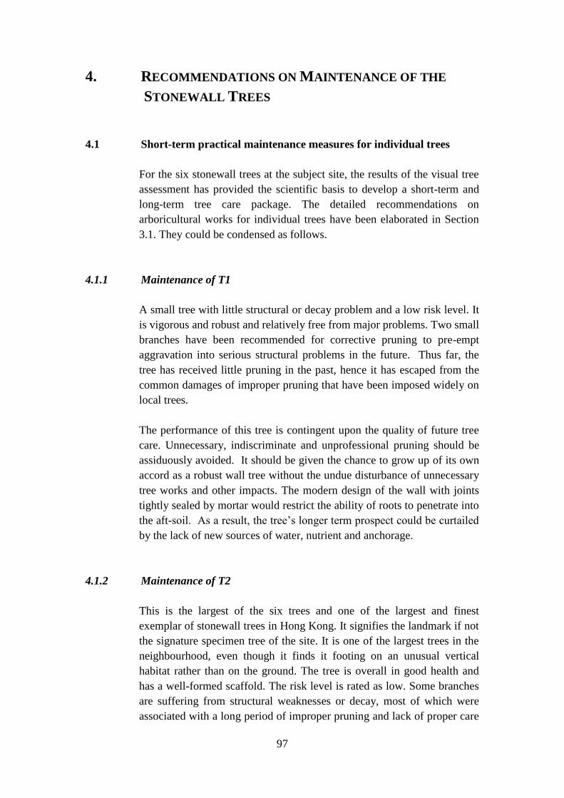
97
4. RECOMMENDATIONS ON MAINTENANCE OF THE
STONEWALL TREES
4.1 Short-term practical maintenance measures for individual trees
For the six stonewall trees at the subject site, the results of the visual tree
assessment has provided the scientific basis to develop a short-term and
long-term tree care package. The detailed recommendations on
arboricultural works for individual trees have been elaborated in Section
3.1. They could be condensed as follows.
4.1.1 Maintenance of T1
A small tree with little structural or decay problem and a low risk level. It
is vigorous and robust and relatively free from major problems. Two small
branches have been recommended for corrective pruning to pre-empt
aggravation into serious structural problems in the future. Thus far, the
tree has received little pruning in the past, hence it has escaped from the
common damages of improper pruning that have been imposed widely on
local trees.
The performance of this tree is contingent upon the quality of future tree
care. Unnecessary, indiscriminate and unprofessional pruning should be
assiduously avoided. It should be given the chance to grow up of its own
accord as a robust wall tree without the undue disturbance of unnecessary
tree works and other impacts. The modern design of the wall with joints
tightly sealed by mortar would restrict the ability of roots to penetrate into
the aft-soil. As a result, the tree’s longer term prospect could be curtailed
by the lack of new sources of water, nutrient and anchorage.
4.1.2 Maintenance of T2
This is the largest of the six trees and one of the largest and finest
exemplar of stonewall trees in Hong Kong. It signifies the landmark if not
the signature specimen tree of the site. It is one of the largest trees in the
neighbourhood, even though it finds it footing on an unusual vertical
habitat rather than on the ground. The tree is overall in good health and
has a well-formed scaffold. The risk level is rated as low. Some branches
are suffering from structural weaknesses or decay, most of which were
associated with a long period of improper pruning and lack of proper care

98
in the past. These accumulated defects have been identified and a
comprehensive range of arboricultural treatments have been
recommended to rectify them (cf. Section 3.1.3).
A particularly alarming improper treatment is the systematic and repeated
removal of almost all the lower branches over a considerable period. This
type of erroneous and unprofessional pruning is widely practised by local
landscape contractors. The loss of lower branches over an extended period
would suppress the ability of the tree to develop a normal taper. With
inadequate thickness at the trunk base but continual expansion of the
crown, the tree could suffer from the risk of snapping. It is regrettable that
the damage has been quite thoroughly done.
This defect is not easy to correct and it may take a long time to nurture
some new lower branches. It is a somewhat probabilistic venture because
one can only choose from the new epicormic growths to identify the
potential future new branches. If the tree sends out few epicormics or few
qualified epicormics, it may not be possible to accomplish the task in
good time. The exercise demands a high level of skill, supervision and lots
of patience, and it has to be consistently applied over some years to take
effect.
4.1.3 Maintenance of T3
This is a semi-mature Chinese Banyan with a much confined scaffold
development. Two of its three trunks have been truncated. The remaining
one constitutes the bulk of the tree’s biomass, which has been reinforced
by clusters of lignified aerial roots linking between branches and from
branches to trunks. The crown development is limited in terms of its
spread and branch density. It has lost a notable number of limbs and main
branches. The live crown ratio is low, and its vigour is rated as average.
No visible symptoms could be discerned to indicate high risk. The hazard
rating is classified as low. The tree can be helped by removing trunk A
which has been badly decayed with no branches except some sparse
sprouts. The remaining stump of trunk C cannot be removed as it lends
crucial support to trunk B via a bundle of lignified aerial roots. The
truncation tip of trunk C with advanced decay could be removed. Some
wounds left by past limb or main branch removal could be carefully
trimmed. The burden on two branch removal wounds could be alleviated
by selective pruning of their epicormic daughter branches.

99
4.1.4 Maintenance of T4
This is the relatively stronger tree amongst the group of four stonewall
trees growing at the eastern part of the wall. The twin-stemmed tree has
strong trunks well reinforced by lignified aerial roots. No trunk is missing
or has been truncated. The crown development, stifled by competition for
space with neighbour trees, has been curtailed. A notable number of limbs
and main branches have been removed or have broken off. Most branch
loss wounds are beset by decay. The foliage density is sparse and the live
crown ratio is rather low at less than 50%.
Trunk A is tilted at 52 degree towards Bonham Road and trunk B at 49
degree towards St Stephen’s Lane. Both leaning angles are the highest
amongst the six trees. The bulk of the tree’s crown weight is carried by
trunk A. It is alarming that the trunk base has been slightly detached from
the wall face. It indicates the incipient failure of the root anchorage. This
critical defect could aggravate and lead to tree collapse in the worst-case
scenario. Something concrete and effective must be implemented as soon
as possible to support the tree and stop the drop. A cable bracing system is
proposed, preferably to be anchored on the nearest building at St
Stephen’s Lane. If this is not feasible, a strong steel frame can be mounted
on the ground of St Stephen’s Lane adjacent to the parapet wall. If cable
bracing is found not feasible, the last resort is to construct a specially-
designed spacing-saving steel frame at the narrow Bonham Road
pavement to prop the tree.
The decayed and fractured wounds should be trimmed and cleaned up.
The end weight of tipped branches carrying heavy loads of epicormic
replacement branches should be appropriately reduced. Stubs should be
removed.
4.1.5 Maintenance of T5
This is the feeblest of the four trees found at the eastern part of the wall.
The single trunk of the slender tree supports a disproportionally small
crown that is squeezed tightly between T4 and T6. Most of the lower
limbs and branches have been removed or lost. The cutting wounds have
been infected by wood-decay fungi. They need to be cleaned up by
careful trimming or remedial pruning. Two specific structural defects
demand attention, including the V-crotch between the only two ascending
limbs, and a seam with bulgewood on the heavy limb.

100
The most critical issue is the development of large basal cavity with
continued wood decay on its greatly reduced residual wall thickness. The
tree has responded to the reduction in wood strength by developing strong
response wood on and around the cavity. It has also formed two strong
lignified aerial roots around the trunk base and a thickened root prop
below the trunk base to provide compensatory reinforcement. Despite
these self-help by the tree itself, the high pedestrian vehicular volume at
the site demands additional assurances. A cable bracing system is
recommended to pull the tree towards the south. The cable preferably
should be anchored on the adjacent building at St Stephen’s Lane. If it is
not possible, a strong steel frame can be mounted on the edge of the
parapet wall at the Lane’s edge to hold the cable.
4.1.6 Maintenance of T6
This is situated at the far eastern end of the wall. The main trunk of the
twin-stemmed tree is tilted heavily towards the east and Bonham Road.
Akin to its companions on the same wall section, its crown development
has been stifled due to the lack of growth space. With freedom from
competition, its eastward crown extension is notably better. The resulting
crown is highly asymmetrical, with most of the biomass concentrated on
the east side. Due to the heavy pedestrian and vehicular traffic at the site,
the tree can be rendered safe by installing a simple cable bracing system
that is similar to the one recommended for T5. The branch removal
wounds with decay and the heavy epicormic growths can be trimmed.
101
4.2 Long-term practical tree maintenance measures
After conducting the long overdue remedial tree works, future tree care
must follow the best international practice to prevent introducing or
inducing new problems. In the long term, measures could be taken to
enhance their growth and safety. Some generic measures can be
implemented to enhance long-term welfare of the six stonewall trees.
4.2.1 Install soil strips at wall crest and toe
A soil strip could be installed at the crest to promote growth of new roots
so as to reinforce tensional pull at the critical position. A strip of the
concrete paving at the wall crest adjacent to the trunk base of the six
stonewall trees can be removed to expose the underlying soil. If necessary,
soil amendments and surface mulches can be added to improve the soil
condition. Roots have the tendency to grow backwards into the soil strip
to provide a new means of tension pull to strengthen tree stability. The
additional supply of water and nutrients will also facilitate tree growth
and health.
Similarly, a soil strip can be installed at the wall toe to enlarge the soil
catchment volume for additional supply of water and nutrients. It means
removal of the present U-channel at the wall toe for T3, T4 and T5. The
surface water at present drained away via the U-channel can infiltrate into
the soil via the new soil strip. For T1, T2 and T6, the unit pavers laid
against the wall toe could be removed to expose the soil and facilitate root
entry into the soil. This new soil strip can bring immediate benefits to T2
to T6, because their surface roots have already reached the pavement
level and penetrated into the soil under it. More new roots are expected
to make use of the new opportunity to grow into the soil strip.
However, for T1 which is still small and does not yet have long surface
roots extending to the wall toe, the soil strip installation could be
postponed. In the long term, the surface roots of T1 could eventually
grow into the wall toe soil strip to furnish a new and important source of
sustenance to the tree. As the wall supporting T1 is of modern design with
little accessible joints for root penetration, the provision of soil strips at
both the wall crest and wall toe can notably enhance its future growth.
They can literally provide a new lease of life to the otherwise sequestered
tree roots.
To preserve the walkable width at the narrow pavement and to avoid
human-foot trampling of soil, a metal grille could be placed on the soil

102
strip. The advice of a geotechnical engineer should be sought in the
design of the soil strips. If a continuous soil strip is not feasible, an
intermitted strip could be adopted instead.
4.2.2 Remove joint seals to permit new root penetration
The continued entry of roots into joints is crucial to provide a new crop of
roots for the tensional pull of the tree against overturning. As the trees
grow bigger, they need to have a corresponding increase in roots to hold
their biomass and capture more water and nutrients. However, the joints
between masonry blocks on the old retaining wall have been sealed
thoroughly in recent years by cement, thus stopping their penetration by
new tree roots. The rigid cement seal plastered around existing roots also
restricts their diameter expansion and may cause girdling injury as they
continue to thicken. The wall supporting T1 is an outlier as it is of
modern design with joints originally sealed by mortar.
Losing the ability to send new roots into the aft-soil and at the same time
losing existing roots could jeopardize tree stability. Where the roots are
physically obstructed, localized removal of the cement seal could be
considered to permit some new roots to grow into the joints and existing
roots to expand. This way, the continued growth and stability of the trees
will not be unduly suppressed. Such a relief can release the trees from a
stifling if not daunting bondage, and ameliorate a potential risk factor
faced by the stonewall trees.
4.2.3 Prevent wedging effect on tree stability
The organic litter and rubbish that tend to accumulate in the gap between
the trunk base and wall face could pose a danger to the trees. As a
stonewall tree tends to swing slightly in strong wind, the gap could be
temporarily widened by a small bit to allow the accumulated debris to
drop further down into the crevice. The trapped debris would create the
wedging effect to prevent the tree to bounce back to its original position.
The process could be repeated, and the cumulative effect of repeated
wedging could be alarming.
Gradually, the gap could be widened to jeopardize tree stability. The
debris in the gap should be removed diligently and thoroughly on a
regular basis to forestall a precipitating cause of stonewall tree
detachment which may lead to tree failure. A non-destructive method
using a trash picker in conjunction with a brush with long and somewhat

103
firm bristles could be employed to clean the gap on a regular basis. In
addition to preventing the wedging effect, the cleaning could prevent the
accumulation of moisture in the gap so as to avoid fungal growth at the
critical trunk base position.
4.2.4 Stop repeated removal of lower branches
All the trees except the very young T1 have lost an inordinate amount of
lower branches from their trunks. This wholesale loss of lower branches
is a rather common phenomenon afflicting other trees in Hong Kong. It is
unlikely that natural causes such as strong wind could preferentially
remove the lower branches so thoroughly on so many trees. Field
observation of pruning works in action would reveal the widely-adopted
but erroneous pruning practice.
This highly undesirable pruning method is probably based on the
mistaken idea that the lower branches are relatively shaded and hence
they play little role in photosynthesis and plant food production. It is also
possible that lower branches are relatively easy to reach and remove in
comparison with the higher-up branches. The common use of the
hydraulic platform in pruning work in Hong Kong, instead of employing
a tree climber, means that the upper part of the crown of large trees could
not be easily reached. This may induce the concentration of pruning in the
lower reachable parts of the crown.
The repeated removal of lower branches can reduce the natural ability of
trees to develop a proper trunk taper. The base of the trunk, deprived of
sufficient and timely increase in diameter, in time may not be able to
support the expanding crown with increasing weight. Thus an originally
healthy and well-structured tree could be unintentionally and
unknowingly transformed over the years into a potential hazard tree by
this unprofessional pruning practice. The affected tree is prone to snap at
the trunk base. Contractors could be coached the proper pruning methods
and be weaned from the harmful approach. Briefing and close supervision
of contractors are necessary to forthwith stop this rather pervasive
negative impact.
4.2.5 Stop unprofessional and unnecessary pruning practice
Unnecessary removal of non-defective and non-hazardous branches
appears to be rather common in tree care works in Hong Kong, including
the management of the six stonewall trees. Every pruning task should

104
have a clearly considered and explained objective, which should be based
firmly on detailed scientific assessment of the tree in the field. The
principal reasons for pruning should be removal of defective branches and
abatement of hazard or nuisance. Pruning without a defined objective is
akin to shooting without aiming.
A pruning proposal that can result in significant reduction in crown size,
such as crown lifting, crown lowering, crown shaping, crown reduction,
and substantial truncation and shortening of large branches, must not be
approved if they are not supported by scientifically justifiable reasons. A
pruning proposal that can incur deformation of the natural crown form,
such as wholesale removal of branches in a given part of the crown, must
not be approved. Contractors should not be given a free hand to prune
without a well justified written pruning plan, which must be approved by
a relevant professional officer who is equipped with specialist tree
knowledge and practice experience.

105
4.3 Preventing grave impacts of excavation
Excavation work at the wall crest platform and wall toe can impose grave
harms on tree roots and hence on tree health and stability. This source of
potential massive injury which could irreversibly dampen and destabilize
stonewall trees must be avoided. If it cannot be avoided, the excavation
must follow strictly the following guidelines to minimize its short- and
long-term impacts:
Demarcation of tree protection zone (TPZ) around the affected
stonewall tree. A recommended TPZ should cover the wall toe
platform, wall face and wall crest platform, with a radius equal to the
average crown diameter. It should include the soil below the wall toe
platform down to 1 m, and the soil behind the wall face and below the
wall crest platform. It should also include the air space above the TPZ
to exclude impacts on the crown.
As far as possible, do not permit excavation in the TPZ. Alternative
location, routing and detour for the proposed excavation must be
seriously considered.
Excavation should be located at a maximum possible distance from
the TPZ.
Digging within the TPZ should only be adopted as absolutely the last
resort.
Excavation depth and width should be minimized.
The duration of opening must be minimized.
If the work has no choice but to intrude into the TPZ, the no-dig, or
trenchless, or micro-tunnelling, or precision directional drilling
techniques should be employed in lieu of open trenching within the
area defined by the TPZ.
Within the TPZ, only the required pipe or cable should be installed.
Other ancillary but obtrusive installations such as junction boxes
which will cut roots and permanently eliminate soil volume for root
growth must not be placed inside the TPZ.

106
Assess impact of excavation on tree stability, and if necessary, provide
cable bracing or propping to prevent tree failure due to the degradation
of root anchorage.
Install hard, rigid and effective protective shields to prevent
mechanical damage to any tree parts, including roots, trunk, branches
and foliage. They should be removed as soon as they have served their
purpose.
Prevent rainwater or construction wastewater from flowing into the
opened pit or trench. Install water-tight bunds around the TPZ
perimeter to prevent flowing of water from the work site into the TPZ.
Use manual tools for excavation in and near TPZ. Light-weight and
low-impact pneumatic digging machines could be used only for
breaking the paving, and should be approved before any operation.
After rainfall, water that stands in the pit or trench (not draining away
by gravity) for more than 30 minutes should be pumped out within 30
minutes.
Take away tall excavated paving materials from the site; do not dump
them into the pit or the trench.
Minimize the cutting of roots encountered in the course of digging.
Ensure proper protection of roots encountered in the course of digging
from mechanical damage and desiccation. All exposed roots should
be wrapped by three layers of hessian and should be kept moist all the
time by spraying with water.
Refill the pit or trench with a good quality soil mix.
Prevent soil degradation and root damage in the course of installing
the new paving.
Depending on the specific conditions of the tree, wall and environ, a
dedicated method statement must be developed and approved before
any excavation work can start.

107
4.4 Guidelines to inspect and monitor tree structural stability and health
The visual tree assessment method, specially developed to cater to
stonewall trees, has been adopted in this study (cf. Tables 1 to 6). By
applying this dedicated method, stonewall trees could receive a
comprehensive, scientific and objective assessment that is commensurate
with the unique tree and habitat characteristics. In the course of field
assessment, individual trees can be subject to a systematic and thorough
evaluation of all the major tree parts. The table is divided into nine
sections to organize the field assessment in a logical sequence, and to
ensure that all the critical features are covered.
Part A covers the basic attributes of the wall, habitat and environs, as well
as recording the pertinent measurements of the wall and tree dimensions
and related geometrical properties. Part B prompts the assessor to inspect
the main components of the tree, beginning with the surface roots, aerial
roots, and ground roots at wall toe. Part C draws the assessor attention to
the crown and the main scaffold. Part D tackles the trunk. Part E focuses
on the crotch between the trunk and limbs, and Part F the limbs and main
branches.
Integrating the assessment results of Parts A to F, Part G conducts a
hazard tree assessment to rate the tree and establish its hazard rating score.
Part H begins to apply the knowledge acquired thus far to practical tree
management. It offers a wide range of specific arboricultural
recommendations to ameliorate the identified tree problems and to
improve tree growth and safety. Part I is linked to Part H to explain the
rationales of the critical recommendations, and elaborate on the treatment
methods.
The stonewall tree assessment should be implemented by a tree specialist
with conceptual and practical experience in this special type of habitat and
their companion trees. All recommended arboricultural works should be
implemented by a skilful and experienced arborist. The minimum
qualifications of the arborist should be a recognized degree in a relevant
field, including arboriculture, forestry, horticulture, ecology or botany. It
should be accompanied by not less than three years of relevant experience
acquired in Hong Kong or in the humid-tropical Asian region with similar
tree species composition and climatic conditions. Besides the above
formal training and qualification, a relevant certification by a recognized
international or national tree care professional body is required.
The critical issues identified in the baseline survey could be given special
attention in the fellow-up monitoring surveys. Thereafter, the stonewall

108
trees can normally be inspected once per year using the dedicated method.
For trees beset with high risk factors, the inspection frequency should be
raised to half-yearly or quarterly. In other words, the inspection frequency
could be increased in tandem with the degree of hazard. New critical
issues should be recorded in the course of the monitoring surveys. For
trees affected by construction activities, the monitoring frequency should
be monthly. The monitoring survey should be conducted as soon as
possible after a typhoon strike with signal 8 and above.
As tree risk assessment is dependent very much on clear visual images,
the baseline survey should build up a detailed photographic record.
Subsequent monitoring surveys should take photographs of existing and
new critical issues. All photographs should be of high quality and high
resolution of preferably not less than 2M per file and in jpeg format. The
photographs should be amply annotated. The relevant items in the
assessment report should be liberally linked to the photographs by citing
the reference number.
The approach begins with collection of comprehensive data on each tree,
from which practical tree care recommendations are inspired or distilled.
Officers with a sound tree knowledge base could learn the technique and
apply it to stonewall trees. It will be helpful if the officer charged with this
duty could learn the concepts and practice in both the classroom and the
real-world environment.

109
5. EXECUTIVE SUMMARY
5.1 Preamble
Six stonewall trees are dwelling on an old masonry retaining wall at a
prominent location at Bonham Road near the Park Road junction. The
Highways Department has been assigned the management responsibility of
the wall and its companion trees. The road, the wall and at least one of the
trees have existed in the neighbourhood for more than a century. With
historical and heritage significance, they furnish outstanding landmark
features and conjure up collective memory for the community. As prized
assets, they deserve special attention and care to ensure their sustainability.
The important stonewall trees have been managed on a regular basis to
maintain their health and vigour. As stonewall trees have rather unique
growth habits and habitat conditions, general knowledge and practice in
tree science are not directly applicable. A detailed and dedicated scientific
study could yield useful information and insights to further enhance the
quality and effectiveness of management.
As the road under the trees is heavily used by both pedestrians and
vehicles, it is necessary to ensure that they are stable and safe. They call
for a thorough risk assessment using the state-of-art methodology. From
the results and findings of the comprehensive study, specific arboricultural
recommendations could be distilled to tackle tree growth and structural
issues. They can also provide a firm basis to develop a long-term
management strategy.
5.2 Study objectives
This study has been commissioned by the Highways Department to fulfil
eight key objectives:
Review the general development of stonewall trees on retaining
structures in Hong Kong.
Analyse the effect of stonewall trees on retaining structures based on
tree failure records.
Identify the factors affecting the stability and health of stonewall trees
based on literature review.

110
Conduct detailed tree risk assessment of the six subject trees.
Appraise the value and potential risks of the six trees to the local
community.
Review the potentials and limitations in preserving them.
Formulate short and long term maintenance measures to enhance their
sustainability.
Prepare guidelines to inspect and monitor the structural stability and
health of the stonewall trees.
The deliverables include a report and a presentation at a seminar. The main
results, findings and recommendations are condensed below.
5.3 Background and general concerns
The extensive construction of masonry retaining structures echoes a
pragmatic response to our urban development history in a difficult
terrain.
Stone retaining walls embedded in built-up areas offer artificial cliff
habitats that are colonized by spontaneous vegetation.
Due to the highly stressful habitat conditions, the probability of
successful tree establishment on stone walls is rather low.
Banyan trees, especially those with strangler fig characters, are pre-
adapted to grow on the harsh vertical habitats.
Stonewall trees constitute an outstanding landscape and ecological
endowment of the city.
No other place in the world has such a rich endowment of stonewall
trees, making them particularly valuable as both cultural and natural
heritage.

111
5.4 Effect of stonewall trees on retaining structures
Past retaining wall failures as indicated by records were largely
attributed to inadequacies in wall design, workmanship and
maintenance.
Most stone wall failures did not involve stonewall trees, and stonewall
trees were attributed as one of the possible causes in the collapse of a
small wall.
There is no record of stonewall tree collapse causing notable damage
to masonry retaining walls.
Stonewall tree failure could be induced by human disturbance of
cutting of critical tension roots.
Stonewall trees could collapse in strong wind due to inadequate growth
of tension roots through the joints into the soil behind the wall.
A dense network of surface roots covering the stone wall face may
protect and stabilize the masonry structure.
5.5 Factors on tree stability and health
Intrinsic wall factors include gaps between masonry blocks; stone size
and length of joints; stone shape and horizontal joints; wall inclination;
wall height; original joint filling; cement sealing of dry wall joints;
weathering state of masonry blocks; seepage on wall face; and weep
holes.
The quality of the wall environs exerts its influence through the factors
of moisture supply of aft-soil; volume of aft-soil; quality of aft-soil;
wall-crest slope with unsealed soil; wind exposure; solar access; air
quality; and proximity to buildings and roads.
The extrinsic impacts on walls and environs includes soil nail
installation and grouting damage; stabilization treatment of contiguous
wall crest and toe slopes; soil disturbance at contiguous paved areas at
wall toe and wall crest; skin wall impact; and trenching damage of tree
roots at wall crest and wall toe.
112
The stonewall tree factors include tree species; tree dimensions; tree
biomass structure; tree lean; root growth habit; and quality of pruning
work and tree maintenance.
5.6 Tree values, potential risks and preservation
The value of stonewall trees is due to their status as world-class and
unique urban ecological gem, spontaneous nature in built-up areas,
multiple amenity functions to people, historical and heritage
significance, and diminishing and threatened resource.
The risk to local community is related to wall instability and tree
instability; historical records indicate minimal contribution of tree
failure to wall failure; in-depth understanding, assessment of tree risk
coupled with preventive and ameliorative measures could minimize
tree failures and their impacts.
Tree preservation is favoured by site conditions with little conflicts
with surrounding buildings and roads; welcomed ecosystem services
bestowed on the neighbourhood; sentimental attachment of local
community to the trees and hence support of tree preservation.
Tree preservation is limited by the lack of space and anchor positions
for cable bracing or installation of propping frame, and the need to
puncture the heritage wall feature if the propping option is chosen.
5.7 Tree risk assessment and arboricultural recommendations
T1: Small tree with few structural and decay problems; high live crown
ratio; free from legacy of past unprofessional pruning; only requires
minor corrective pruning.
T2: Largest, oldest and most outstanding stonewall tree; significant
height, crown spread and trunk diameter; well balanced and quite full
crown development; one of the top-ranking stonewall trees in Hong
Kong; designated as OVT; well-formed scaffold with three codominant
trunks; multiple branch defects and wound decay induced largely by
past poor pruning practice; some heavy epicormic load on decayed
tipping wounds; excessive removal or loss of lower branches with
implications on tree stability; no visible imminent high risk symptoms.

113
T3: Two of three trunks truncated with decayed tip; limited and
confined crown development; extensive loss of limbs and branches;
excessively loss of lower branches; low live crown ratio; liberal
reinforcement of tree structure by bundles of lignified aerial roots;
most branch loss wounds beset by decay; two heavy epicormic
branches; no visible imminent high risk symptoms.
T4: Twin stemmed tree with relatively stout trunks; heaviest lean of
the six trees; low live crown ratio; confined crown development;
wound decay at branch removal wounds; heavy epicormic branches
attached to decayed tipping wounds; excessive removal or loss of
lower branches; alarming risk due to incipient anchorage failure; needs
support by cable bracing or propping.
T5: Single trunk; high height to DBH ratio; low live crown ratio;
narrow and confined crown; only two limbs and few branches;
compression fork between two limbs; decayed wounds; alarming risk
due to large basal cavity partly compensated by response wood at
cavity edge, two lignified root stands and a natural root prop; needs
support by cable bracing or propping.
T6: Twin-stemmed tree; one trunk carrying the bulk of the crown load
is heavily tilted; low live crown ratio; excessive removal or loss of
lower branches; decayed branch loss wounds; risk due to unbalanced
biomass distribution plus heavy lean; needs support by cable bracing.
5.8 Long-term practical tree maintenance measures
Install soil strips at wall crest and toe to facilitate root growth to
stabilize anchorage and increase supply of water and nutrients.
Remove joint seals at suitable locations to permit new root penetration
and existing root expansion, so that the continued increase in tree size
and weight could be matched by corresponding increase in new roots.
Prevent wedging effect on tree stability by regular removal of organic
debris and rubbish deposited at the gap between trunk base and wall
face.
Stop repeated removal of lower branches and unprofessional and
unnecessary pruning practice by demanding well-justified tree pruning
proposals and reinforcing coaching of contractors.

114
Prevent extremely harmful impacts of excavation in the tree protection
zone of stonewall trees, and establish strict guidelines on work inside
the zone.

115
REFERENCES
Agriculture, Fisheries and Conservation Department, 2004. Check List of Hong Kong
Plants 2004. Hong Kong Herbarium, Bulletin 1, Government of HKSAR.
Agriculture, Fisheries and Conservation Department, 2007, 2008, 2009, 2011. Flora
of Hong Kong, Volumes 1 to 4, edited by Hong Kong Herbarium and
South China Botanical Garden, Government of HKSAR.
Aslan, M., Atamov, V., 2006. Flora and vegetation of stony walls in south-east
Turkey (Şanliurfa). Asian Journal of Plant Sciences 5, 153-162.
Bolton, D.E., 1985. Living walls of Exeter. The Journal of the Devon Trust for Nature
Conservation 6, 51-66.
Breuste, J., Feldmann, H., Uhlmann, O., 1998. (Eds.) Urban Ecology. Springer, Berlin.
Chan, Y.C., 1996. Study of Old Masonry Retaining Walls in Hong Kong. GEO
Report No. 31, Geotechnical Engineering Office, Civil Engineering
Department, Hong Kong.
CEDD, 2012. Slope Information System. Civil Engineering and Development
Department, HKSAR Government.
http://hkss.cedd.gov.hk/hkss/eng/slopehttp://hkss.cedd.gov.hk/hkss/eng/slopei
nfo/disclaimer1.asp?type=sisinfo/siswelcome.asp, accessed on 01 August
2012.
Clark, J.R., Matheny, N.P., 1993. A Handbook of Hazard Tree Evaluation for Utility
Arborists. International Society of Arboriculture, Savoy, IL, 34 pp.
Darlington, A. (Ed.), 1981. Ecology of Walls. Heinemann Educational, London.
Deakin, R., 1855. Flora of the Colosseum of Rome. Groombridge and Sons, London.
de Neef, D., Stewart, G.H., Meurk, C.D., 2008. Urban biotopes of Aotearoa New
Zealand (URBANZ) (III): spontaneous urban wall vegetation in Christchurch
and Dunedin. Phyton Horn Austria 48, 133–154.
dos Reis, V.A., Lombardi, J.A., de Figueiredo, R.A., 2006. Diversity of vascular
plants growing on walls of a Brazilian city. Urban Ecosystems 9, 39-43.
Duchoslav, M., 2002. Flora and vegetation of stony walls in East Bohemia (Czech
Republic). Preslia, Praha 74, 1-25.

116
Figueiredo, R.A., Motta Junior, J.C., Vasconcellos, L.A.D.S., 1995. Pollination, seed
dispersal, seed germination and establishment of seedlings of Ficus
microcarpa, Moraceae, in southeastern Brazil. Revista Brasileira de Biologia
55, 233-239.
Francis, R.A., Hoggart, S.P.G., 2009. Urban river wall habitat and vegetation:
observations from the River Thames through central London. Urban
Ecosystems 12, 465-485.
GCW, 2011. Ficus microcarpa (Moraceae). Global Compendium of Weeds,
http://www.hear.org/gcw/species/ficus_microcarpa, accessed on 20 September
2011.
Geotechnical Engineering Office (GEO), 1993. Guide to Retaining Wall Design,
second edition. Geoguide 1, Civil Engineering Department, Hong Kong
Government, Hong Kong.
Geotechnical Engineering Office (GEO), 2010. Review of the 3 June 2007 failure of a
masonry retaining wall on hillside adjacent to no. 84 Peak Road. GEO Report
No. 250, Geotechnical Engineering Office, Civil Engineering and
Development Department, Geotechnical Engineering Office,
Geotechnical Engineering Office (GEO), 2011. Study on Masonry Walls with Trees.
GEO Report No. 257, CM Wong & Associates, Geotechnical Engineering
Office, Civil Engineering and Development Department, The Government of
the HKSAR.
Geotechnical Engineering Office (GEO), 2011. Technical Guidelines on Landscape
Treatment of Slopes. GEO Publications No. 1/2011. GEO, Civil Engineering
and Development Department, the Government of the Hong Kong Special
Administrative Region.
Geotechnical Engineering Office (GEO), 2011. Study on Masonry Walls with Trees.
GEO Report No. 257. GEO, Civil Engineering and Development Department,
the Government of the Hong Kong Special Administrative Region.
Ghosh, R.B., 1960. Preliminary observations on the flora of dilapidated walls and
buildings of Calcutta and its suburbs. Journal of Indian Botanical Society 39,
584-557.
Ghosh, R.B., Das, D., 2002. Observation in seasonal variation of wall vegetation of
the district of Bankura, West Bengal. Journal of Economic and Taxonomic
Botany 26, 557-561.

117
Gilbert, O., 1992. Rooted in Stone: The Natural Flora of Urban Walls. English Nature,
Peterborough, UK.
Gilman, E.F., 2002. An Illustrated Guide to Pruning, 2rd ed. Delmar, Thomas
Learning, Albany, NY.
Hendry, A.W., Khalaf, F.M. (Eds.), 2001. Masonry Wall Conservation. Spon, London.
Hruška, K., 1987. Syntaxonomical study of Italian wall vegetation. Vegetatio 73, 13-
20.
IFLA, 2011. Ficus microcarpa, laurel fig. Institute of Food and Agricultural
Sciences, University of Florida, http://plants.ifas.ufl.edu, accessed on 20
September 2011.
International Society of Arboriculture, 2011. Glossary of Arboricultural Terms. ISA,
Champaign, IL.
Jim, C.Y., 1990. Trees in Hong Kong: Species for Landscape Planting. Hong Kong
University Press, Hong Kong.
Jim, C.Y., 1994. Champion Trees in Urban Hong Kong. Hong Kong Flora and Fauna
Series, Urban Council, Hong Kong.
Jim, C.Y., 1998. Old stone walls as an ecological habitat for urban trees in Hong
Kong. Landscape and Urban Planning 42, 29-43.
Jim, C.Y., 2006. Chinese Banyan: From Wishing Trees to Wishes for Trees.
Agriculture, Fisheries and Conservation Department, Friends of the Country
Parks and Cosmos Books, Hong Kong.
Jim, C.Y., 2008. Urban Greening in Hong Kong: Exemplary Designs and Delights.
C&C Joint Printing and Green Fun Committee, Hong Kong
Jim, C.Y., 2008. Urban biogeographical analysis of spontaneous tree growth on stone
retaining walls. Physical Geography 29, 351-373.
Jim, C.Y., 2010. Old masonry walls as ruderal habitats for biodiversity conservation
and enhancement in urban Hong Kong. In: Müller, N., Werner, P., Kelcey, J.G.
(Eds.) Urban Biodiversity and Design. Blackwell Publishing, Oxford, pp. 323-
347.

118
Jim, C.Y., Chen, W.Y., 2010. Habitat effect on vegetation ecology and occurrence on
urban masonry walls. Urban Forestry and Urban Greening 9: 169-178.
Jim, C.Y., Chen, W.Y., 2011. Bioreceptivity of buildings for spontaneous arboreal
flora in compact city environment. Urban Forestry and Urban Greening 10:
19-28.
Karschon, R., Weinstein, A., 1985. Wall flora and vegetation at Qal‘at Nimrud, the
Castle of Banyas. Israel Journal of Botany 34, 59-64.
Kent, D.H., 1961. The flora of Middlesex walls. The London Naturalist 40, 29-43.
Kolbek, J., Valachovic, M., 1996. Plant communities on walls in North Korea: a
preliminary report. Thaiszia Journal of Botany 6, 67-75.
Laman, T.G., 1995. The ecology of strangler fig seedling establishment. Selbyana 16,
223-229.
Larson, D.W., Matthes, U., Kelly, P.E., Lundholm, J.T., Gerrath, J.A., 2004. The
Urban Cliff Revolution: New Findings on the Origins and Evolution of
Human Habitats. Fitzhenry and Whiteside, Markham, Toronto.
Lisci, M., Pacini, E., 1993. Plants growing on the walls of Italian towns 1. sites and
distribution. Phyton 33, 15-26.
Lisci, M., Pacini, E., 1993. Plants growing on the walls of Italian towns 2.
reproductive ecology. Giornale Botanico Italiano 127, 1053-1078.
Lo, H.L., 1971. The early history of masonry works in Hong Kong and their
relationship with local construction industry. Food and Commodity Monthly 9,
459-462.
Lonsdale, D., 1999. Principles of Tree Hazard Assessment and Management. HMSO,
London.
Matheny, N.P., Clark, J.R., 1994. A Photographic Guide to the Evaluation of Hazard
Trees in Urban Areas, 2nd ed. International Society of Arboriculture, Savoy,
IL.
Mattheck, C., 2002. Tree Mechanics. Karlsruhe Research Centre, Karlsruhe, Germany.
Mattheck, C., 1998. Design in Nature: Learning from Trees. Springer, Heidelberg,
Germany.

119
Mattheck, C., Breloer, H., 1994. The Body Language of Trees. HMSO, London.
McPherson, J.R., 1999. Studies in urban ecology: strangler figs in the urban parklands
of Brisbane, Queensland, Australia. Australian Geographical Studies 37, 214-
229.
Morgenstern and Geotechnical Engineering Office, 2000. Report on the Kwun Lung
Lau landslide of 23 June 1994. GEO Report No. 103, Geotechnical
Engineering Office, Civil Engineering and Development Department, The
Geotechnical Engineering Office,
Payne, R.M., 1978. The flora of walls in south-eastern Essex. Watsonia 12, 41-46.
Pokorny, J.D. (coordinating author), 2003. Urban Tree Risk Management: A
Community Guide to Program Design and Implementation. USDA Forest
Service Northeastern Station, St. Paul, MN.
Rishbeth, J., 1948. The flora of Cambridge walls. Journal of Ecology 36, 136-148.
Shigo, A.L., 1983. Tree Defects: A Photo Guide. General Technical Report NE-82,
U.S. Department of Agriculture Forest Service, Northeastern Forest Experiment
Station, Durham, NH.
Shigo, A.L., 1988. A New Tree Biology: Facts, Photos, and Philosophies on Trees and
their Problems and Proper Care, 2nd
ed. Shigo and Trees, Durham, NH.
Shigo, A.L., 1989. Tree Pruning: A Worldwide Photo Guide for the Proper Pruning of
Trees. Shigo and Trees, Durham, NH.
South China Morning Post, 1925. 18 July 1925, 29-31 July 1925, 8 August 1925, 3
and 5 September 1925
Starr, F., Starr, K., Loope, L., 2003. Ficus microcarpa, Chinese Banyan, Moraceae.
United States Geological Survey, Biological Resources Division, Haleakala
Field Station, Maui, HI.
Sukopp, H., Hejný, S., Kowarik, I., 1990. (Eds.) Urban Ecology: Plants and Plant
Communities in Urban Environments. SPB Academic, The Hague.
Segal, S. (Ed.) 1969. Notes on Wall Vegetation. Dr. W. Junk, The Hague.
Woodell, S., 1979. The flora of walls and pavings. In: Laurie, I.C. (Ed.) Nature in
Cities. Wiley, Chichester, pp. 135-157.