Embed Size (px)
Citation preview

http://www.iaeme.com/IJCIET/index.asp 128 [email protected]
International Journal of Civil Engineering and Technology (IJCIET)
Volume 6, Issue 9, Sep 2015, pp. 128-138, Article ID: IJCIET_06_09_012
Available online at
http://www.iaeme.com/IJCIET/issues.asp?JTypeIJCIET&VType=6&IType=9
ISSN Print: 0976-6308 and ISSN Online: 0976-6316
© IAEME Publication
STUDY ON ROADWAY SUBSURFACE
DRAINAGE SYSTEM AND RELATED
PERFORMANCE USING FEM
Thair Jabbar Mizhir Alfatlawi
Lec. Doctor, Civil Engineering Department, Babylon University, Iraq
ABSTRACT
Poor subsurface drainage is one of the factors that causes pavement
distress and reduces pavement service life. The evaluation of roadway
subsurface drainage system required good knowledge in groundwater flow
especially the unsaturated water flow through pavement layers and related
properties that affect the ability of drainage system to remove moisture helds
in base, subbase and subgrade layers. This paper uses the finite element
method (FEM) to solve the well-known unsaturated flow equation called
'Richards Equation' that applied to simulate water flow in roadway subsurface
drainage layers with the presence of edge drain. Three granular bases, five
subgrade soils and one type of trench have been used to study the effect of
pavement layers properties on the performance of subsurface drainage system.
Current study reveals that the performance of drainage system not only
depends on edge drain design but it also heavily depends on subgrade layer
properties. It is found that residual degree of saturation after long time not
highly affected by pressure heads at air entry but this suction pressure affects
the time required to reach the FHWA indicator and the total moisture that
drained by edge drain decreases with the increase of hydraulic conductivity of
subgrade soil.
Key words: Edge Drain, Subsurface Drainage, Unsaturated Flow, Subgrade
Soil, Granular Base, Hydraulic conductivity.
Cite this Article: Thair Jabbar Mizhir Alfatlawi. Study on Roadway
Subsurface Drainage System and Related Performance Using Fem.
International Journal of Civil Engineering and Technology, 6(9), 2015, pp.
128-137.
http://www.iaeme.com/IJCIET/issues.asp?JTypeIJCIET&VType=6&IType=9
1. INTRODUCTION
Highway pavements are very susceptible to the damaging effects of water
which enters the pavement as surface water through cracks, joints, pavement
infiltration and as groundwater from an intercepted aquifer. Edge drains systems that
allow water to filter down through shoulder gravel into trenches and pipes that carry
the water away have been a preferred method for managing subsurface drainage.

Study on Roadway Subsurface Drainage System and Related Performance Using Fem
http://www.iaeme.com/IJCIET/index.asp 129 [email protected]
These systems keep moisture from softening subgrades and reducing the structural
strength of pavement. Longitudinal drains are placed parallel to the pavement
centerline in both the horizontal and vertical alignments. This type of drain consists of
a trench with a perforated collector pipe surrounded by a protective filter. These
drains are usually placed under the pavement edge joints or under shoulders where
most water infiltrates the pavement; but, on wide pavements such as runways they
might also be placed at the center and intermediate points to draw down the water
table. There are some general rules for selecting and placing the perforated or slotted
pipe used in longitudinal and transverse subsurface drainage systems including soil
conditions, load requirements, durability, and environmental conditions. Figure (1)
shows the component of roadway subsurface drainage using edge drain.
2. LITERATURE REVIEW
The problem of draining excess water from beneath highway pavements has
received much attention from pavement designers and researchers for at least 50
years. One of the first sets of design recommendations regarding subsurface drainage
for roadways was published by the Federal Highway Administration (FHWA) in the
early 1950’s. Since that time there have been numerous attempts to develop highway
subsurface drainage and since that time new drainage products and materials have
become available to the designer/contractor for implementation of subsurface
drainage into roadway systems (Canelon and Nieber, 2009).
Cedergreen et al. (1972) evaluated field tests that concerns with both drained
and undrained pavement sections and concluded that to achieve proper drainage,
drains (or ditches) a long side of road are essential to collect water from road surface
and surrounding areas and lead it to an exit point where it can be safely discharged.
The AASHTO Guide for Design of Pavement Structures (1986) included drainage as
an essential element of pavement design, the methods of drainage include: free
draining bases, French drains, pipe and aggregate subdrains and most recently
prefabricated "geocomposite" edge drains. Forsyth (1987) presented the economic
impact of subsurface drainage system taking in account a number of case studies
related to pavement drainage, the researcher confirmed that the use of edge drains
usually improve the durability of pavements. Tart and Rupter (2000) investigated the
influence of rain event on pavement performance. Mallela et al. (2000) considered the
drainage system design and construction. Statistical and numerical modeling of
pavement drainage systems is dealt by Lytton et .al, (1989). Ceylan et al. (2013)
conducted an extensive performance review of primary interstate pavement subdrains
Edge drain
Subgrade
Pavement
Granular base (Subbase)
Shoulder
Water table
Gravel trench
Figure 1 Roadway subsurface drainage system using edge drain

Thair Jabbar Mizhir Alfatlawi
http://www.iaeme.com/IJCIET/index.asp 130 [email protected]
in Iowa and investigated the effect of poor subdrain performance due to improper
design, construction, and maintenance on pavement surface distresses. Zumrawi
(2013) studied the various impacts of inadequate drainage on road pavement
condition and found that most roads in Khartoum State suffered from poor drainage
which causes severe distresses and damages of pavement, design guidelines were
suggested to assist the highway engineers in designing proper drainage to increase
service life of pavement.
3. THEORY
The unsaturated zone is located above the water table. Within this zone, the
pore spaces are usually only partially filled with water. Hence, porosity of soil is
larger than volumetric water content. Due to the fact that water in this zone is held in
the soil pores under surface-tension forces, negative pressures or suction pressures are
developed (Ariza, 2002). Flow through unsaturated soils is complicated to understand
where the permeability coefficient is a function of water content and negative pore
water pressure and proportioned directly with them (Freeze and Cherry, 1979).
Rainfall on pavement runs off and infiltrates through the base, subbase, and subgrade
soils. Infiltration of any layer depends upon its porosity, thickness and quantity of
water present. Water that has entered into the pavement can be carried to edge drains
through permeable layers and then drained out of pavement through outlet pipes.
Under the pavement surface, a certain thickness of treated or untreated aggregates is
placed as base or subbase to endure the compressive load transferred from the surface.
The soil below the subbase works as a bed for those upper layers. Thus, the materials
used in a pavement range from fine clay soil to coarse as gravel, to cohesive as
asphalt and portland cement concrete.
Water flow in the unsaturated zone is solved using a form of the Richards
Equation. Richards Equation is derived from substituting Darcy’s Law into the
unsaturated continuity equation. The unsaturated continuity equation is an expression
for conservation of mass and states that the mass entering a specific volume of interest
less the mass leaving the volume is equal to the change in mass storage with time. It is
expressed as:
where:
θ = volumetric water content, [-],
t = time [T],
x,y,z = dimensional coordinates [L],
ρ = density of fluid [ML –3
], and
qx ,qy ,qz = Darcy’s velocity in three dimensions [LT -1
].
For constant density, the ρ term cancels out on both sides:
Or, can be written using vector calculus form as follows:
In saturated groundwater flow, Darcy's velocity is:

Study on Roadway Subsurface Drainage System and Related Performance Using Fem
http://www.iaeme.com/IJCIET/index.asp 131 [email protected]
Where H= total head [L] and Ksat= saturated hydraulic conductivity (LT-1
).
In the unsaturated states, the movement of the moisture is governed by a
modification of the Darcy Equation suggested by Richards:
In which, the hydraulic conductivity K(h) is defined as function of pressure head
(h) by Richards. Richards Equation is obtained by substituting Richards definition of
hydraulic conductivity for Darcy’s velocity (q) in the continuity equation and
arranging equation (3) to be:
Equation (6) called the mixed form Richards equation.
To complete the model of variably saturated flow, auxiliary relationships that
relate the hydraulic conductivity and moisture content to the pressure head are
needed. Ariza and Birgisson, 2002 gave a detailed literature for these relationships,
especially those suitable for pavement engineering. Recent study adopted Brooks-
Corey model where it verified by many previous studies (Apul et .al, 2002). Brooks-
Corey model suggested the following relationships:
where:
θsat = saturated water content, [-],
θres = residual water content, [-],
hd= pressure head at air entry ,(negative), [L], and
's = materials properties constants [-].
Finite element technique have been used to simulate roadway subsurface
drainage system with the presence of edge drain shown in figure 1, groundwater
modeling software, Mn-Drain, applied to represent both of saturated and unsaturated
flow through the studied system.
The efficiency of edge drain to remove infiltrated water that entered the granular base
classified by FHWA, 1994 depending on the time required to reduce the moisture
content in the granular base from 100% to a moisture level of 85%. Table 1 shows the
pavement rehabilitation guidance manual for time required to lower moisture from
100% to 85%

Thair Jabbar Mizhir Alfatlawi
http://www.iaeme.com/IJCIET/index.asp 132 [email protected]
Table 1 Quality of drainage by edge drain depending on time required to lower moisture
content from 100% to 85% (FHWA, 1994).
Quality Material
Excellent Less than 2 hrs Good 2 to 5 hrs Fair 5 to 10 hrs Poor Greater than 10 hrs
Very poor Much greater than 10 hrs
4. CASE STUDY
4.1. Dimensions and Meshing
Road drainage system concerned in recent study consisted of pavement layer
placed on granular base layer (subbase) of 30cm thickness, assumed to be initially
saturated, laid above a subgrade layer. The water table assumed to be 0.5m below the
granular base. The subsurface drainage system consisted of 10cm radius edge drain,
edge drain laid below road shoulder and along road length through 40cm x 40cm high
permeability gravel trench. The finite element mesh optimized and discretized using
the auto-run mesh routine EasyMesh. A schematic shown in figure 2 explains the
dimensions and meshing geometry of the studied subsurface drainage system.
4.2. Materials
Three granular base types (subbase A, subbase B and subbase C), five
subgrade soils (loamy sand, loam, silt loam, clay and impermeable) and one type of
edge drain trench (gravel) used to study the performance of subsurface drainage
system under variable subbase and subgrade properties. Table 2 shows current
material data, the subgrade data is based on descriptions and values provide with the
HYDRUS2D software, gravel and granular values are selected to provide the range of
observed behaviors. Data in Table 2, are calculated corresponding to Brooks- Corey
model referred to equations 7 and 8.
Figure 2 Case study dimensions (in centimeters) and geometry discretization.
-100
-90
-80
-70
-60
-50
-40
-30
-20
-10
0
10
20
30
40
50
60
70
80
90
100
110
120
130
140
150
160
170
180
190
200
210
220
230
0 50 100 150 200 250 300 350 400 450 500
This is the mesh that will be used in the calculation
Check out dimensions and regions
30cm granular base
50cm subgrade layer above W.T.
40cm*50cm gravel trench
Edge drain of 20cm diameter

Study on Roadway Subsurface Drainage System and Related Performance Using Fem
http://www.iaeme.com/IJCIET/index.asp 133 [email protected]
Table 2 Current study material data.
NO Material 1
(-)
()
θsat
(-)
θres
(-)
hd
(cm)
2
(-)
Ksat
(m/day)
1 Gravel 0.2 0.45 0.03 -0.5 13 0.1
2 Subbase A 0.2 0.45 0.03 -1 13 5x10⁻⁴
3 Subbase B 0.5 0.45 0.03 -2 7 2x10⁻⁴
4 Subbase C 1 0.45 0.03 -5 5 1x10⁻³
5 Loamy sand 0.474 0.401 0.035 -8.7 7.22 1.7x10⁻³
6 Loam 0.22 0.434 0.027 -11.15 12.1 3.67x10⁻⁴
7 Silt loam 0.211 0.486 0.015
-20.75 12.48 1.89x10
-4
8 Clay 0.131 0.385 0.09 -37.31 18.267 1.67x10⁻⁵
9 Impermeable 1 0.4 0.1 -5 5 1x10-20
4.2. Initial and Boundary Conditions
Initially, the granular base assumed to be saturated, so that the initial condition
taken as saturated granular base with zero pressure head. Water table under the
granular base considered as the end of domain and the boundary condition and
pressure head fixed to zero. Nodes lies on the edge drain have zero pressure head
unless this condition caused an influx of moisture into the trench; in this case,
boundary condition replaced by a no flow condition at that node.
5. RESULTS AND DISCUSSTION
A simplified finite element simulation of roadway cross-section, shown in figure 2,
used to illustrate the saturated and unsaturated flow through pavement layers. Figures
3 to 5 show the variation of the degree of saturation with time for different
combinations of granular bases and subgrade soils. It can be seen that with using
impermeable and clayey subgrades, the edge drain no longer able to drain roadway
cross-section under any granular base condition. Other subgrade soils are of
"excellent" drainage according to FHWA, 1994 classification shown in table 1 where
they satisfy the degree of saturation of 85% (S85%) at running time less than 2hrs. On
the other hand, effect of granular base (subbase) properties on drainage system
behavior is clearly appeared at later running time, subbase C results more reduction in
degree of saturation after 10hrs compared with other granular bases under all
subgrade conditions (using of subbase C resulted a degree of saturation less than 45%
for silty loam, loam and sandy loam subgrade soils).
Figure 3 Degree of saturation variation with time (using subbase-A).
Thair Jabbar Mizhir Alfatlawi
http://www.iaeme.com/IJCIET/index.asp 134 [email protected]
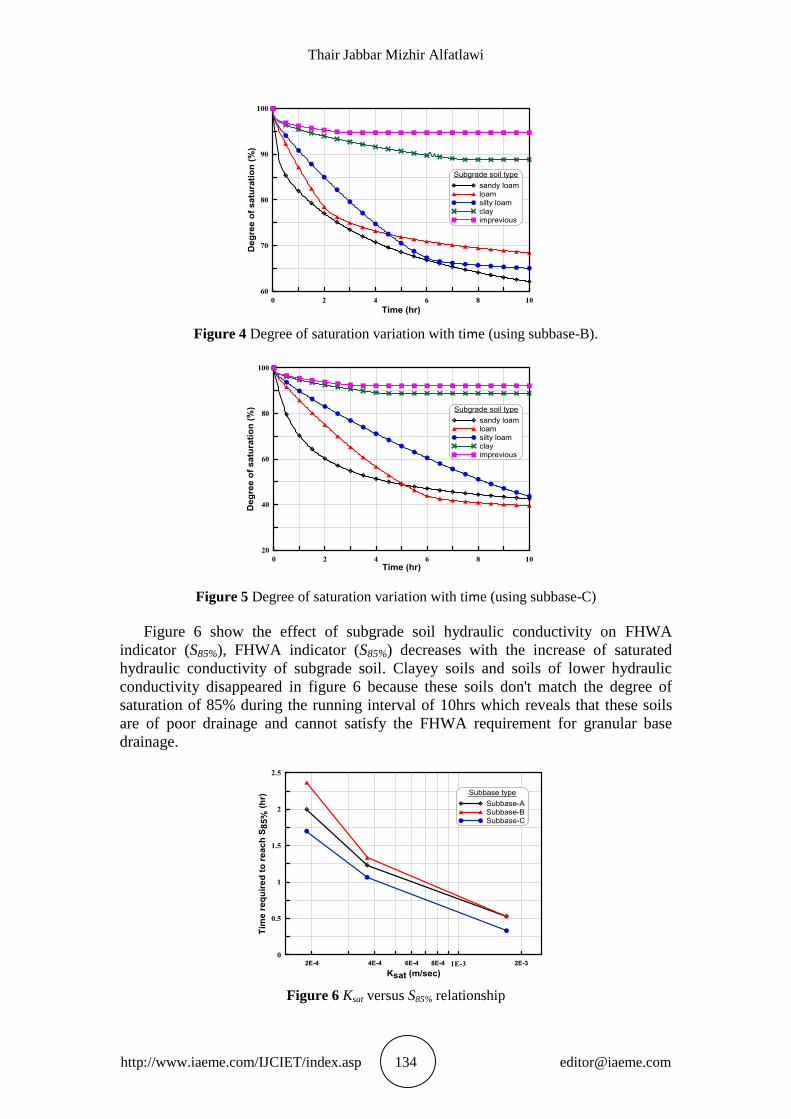
Figure 4 Degree of saturation variation with time (using subbase-B).
Figure 5 Degree of saturation variation with time (using subbase-C)
Figure 6 show the effect of subgrade soil hydraulic conductivity on FHWA
indicator (S85%), FHWA indicator (S85%) decreases with the increase of saturated
hydraulic conductivity of subgrade soil. Clayey soils and soils of lower hydraulic
conductivity disappeared in figure 6 because these soils don't match the degree of
saturation of 85% during the running interval of 10hrs which reveals that these soils
are of poor drainage and cannot satisfy the FHWA requirement for granular base
drainage.
Figure 6 Ksat versus S85% relationship

Study on Roadway Subsurface Drainage System and Related Performance Using Fem
http://www.iaeme.com/IJCIET/index.asp 135 [email protected]
In vadose zone flow, the hydraulic conductivity is a nonlinear function of
volumetric water content as stated in equation 8 and the soil pressure head is negative.
Figures 7 and 8 show the effect of saturated content and pressure head at air entry,
respectively on the time required to reach S85%. The time required to reach S85%
increases as the saturated water content increasing according to figure 7, while the
most negative pressure head at air entry soils requires larger time to reach FHWA
indicator (S85%)
Figure 7 Effect of saturated water content on time required to reach S85%.
Figure 8 Effect of pressure head at air entry on time required to reach S85%.
The variation of total moisture drained by the edge drain with subgrade soil
hydraulic conductivity is shown in figure 9, the relation clarified that the higher the
hydraulic conductivity, the lower the amount of drained by the edge drain. This
behavior may be belonged to the increase of subgrade soil ability to drain granular
base water with the increasing of hydraulic conductivity. The incompatible behavior
of impermeable subgrade layer is expounded where the efficiency of edge drain in
this case is highly reduced because of laying half of the edge drain and the
surrounding gravel trench into an impermeable layer (see figures 1 & 2).
Water content of soils in unsaturated flow is less than porosity, so water will held
between soil grains under the act of surface tension forces. This suction pressure is
affected both water content and hydraulic conductivity. Figure 10 shows that the
increase in pressure head at air entry will cause an increase in the total moisture that
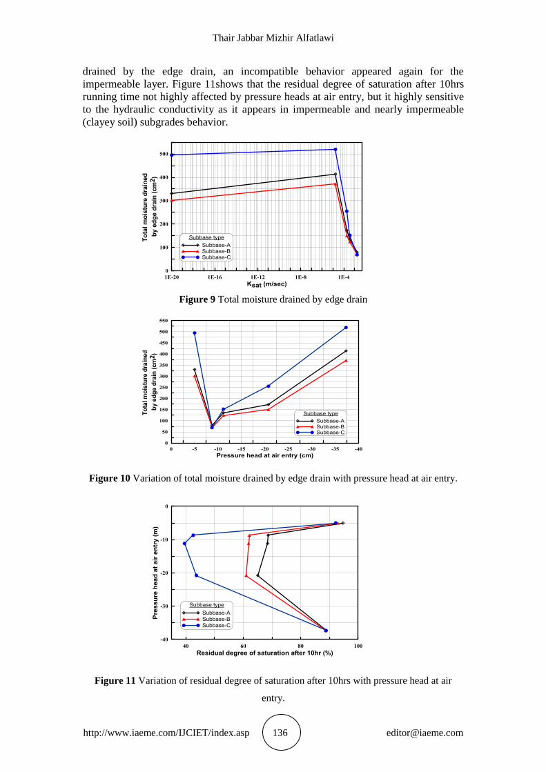
Thair Jabbar Mizhir Alfatlawi
http://www.iaeme.com/IJCIET/index.asp 136 [email protected]
drained by the edge drain, an incompatible behavior appeared again for the
impermeable layer. Figure 11shows that the residual degree of saturation after 10hrs
running time not highly affected by pressure heads at air entry, but it highly sensitive
to the hydraulic conductivity as it appears in impermeable and nearly impermeable
(clayey soil) subgrades behavior.
Figure 9 Total moisture drained by edge drain
Figure 10 Variation of total moisture drained by edge drain with pressure head at air entry.
Figure 11 Variation of residual degree of saturation after 10hrs with pressure head at air
entry.

Study on Roadway Subsurface Drainage System and Related Performance Using Fem
http://www.iaeme.com/IJCIET/index.asp 137 [email protected]
5. CONCLUSIONS
The quality of subsurface drainage is one of the most important factors because poor
drainage leads to distresses and deterioration of road pavement. Numerical study
shows that the performance of drainage system not only depends on edge drain design
but it also heavily depends on subgrade layer properties. The saturated hydraulic
conductivity (Ksat) has a significant effect on drainage efficiency where higher
permeability layer causes an abrupt reduction in the moisture content of road layers.
Impermeable and low permeability (such as clay) subgrade layers not suitable to use
with edge drain for roadway subsurface drainage because it reduces edge drain
efficiency as it fouled a part of edge drain and prevent water to enter easily into the
surrounding gravel trench. The time required to reach FHWA indicator (S85%)
increases as the saturated water content increasing and/or saturated hydraulic
conductivity decreasing. As the pressure head at air entry is a measure to how much a
soil able to retain water, the residual degree of saturation after long time not highly
affected by pressure heads at air entry but it affects the time required to reach the
FHWA indicator. Total moisture that drained by edge drain decreases with the
increase of hydraulic conductivity of subgrade soil. Finally, recent study reveals that
using the unsaturated flow- finite element software (Mn-Drain) is an efficient tool for
subsurface drainage system design and evaluation.
REFERENCES
[1] American Association of State Highway and Transportation Officials, AASHTO
Guide for Design of Pavement Structures. Washington, D.C., 1998.
[2] Apul, D., Gardner, K., Eighmy, T., Benoit, J. and Brannaka, L. A Review of
Water Movement in the Highway Environment: Implications for Recycled
Materials Use, Recycled Materials Resource Center, University of New
Hampshire, Durham, New Hampshire, 2002.
[3] Ariza, P. and Birgisson, B. Evaluation of Water Flow through Pavement Systems,
Minnesota Department of Transportation, Report No. MN/RC - 2002-30, 2002.
[4] Ariza, P. Evaluation of Water Flow through Pavement Systems, M.Sc. Thesis,
University of Florida, Minnesota Department of Transportation, 2002.
[5] Canelon, J. D. and Nieber, J. L. Evaluating Roadway Subsurface Drainage
Practices. Minnesota Department of Transportation, Research Services Section,
2009.
[6] Cedergreen, H.R., O’Brien K.H., and Arman J.A. Guidelines for the Design of
Subsurface Drainage Systems for Highway Structural Sections. Publication No.
FHWA-RD-72-30, Washington, D.C., 1972.
[7] Ceylan, H., Gopalakrishnan, K., Kim, S., and Steffes, R. F. Evaluating Roadway
Subsurface Drainage Practices. InTrans Project Report 12-428. Ames, Iowa:
Institute for Transportation, Iowa State University, 2013.
[8] FHWA, Drainable Pavement Systems - Instructor's Guide, Demonstration Project
87, Publication No. FHWA-SA-94-062, Office of Technology Applications and
Office of Engineering, Federal Highway Administration, Washington, D.C.,
1994.
[9] Mustafa Hamid Abdulwahid and Kadhim Naief Kadhim. Application of Inverse
Routing Methods to Euphrates River (IRAQ). International Journal of Civil
Engineering and Technology, 4(1), 2013, pp. 97 - 109.

Thair Jabbar Mizhir Alfatlawi
http://www.iaeme.com/IJCIET/index.asp 138 [email protected]
[10] Forsyth, R.A. the Economic Impact of the Pavement Subsurface Drainage.
Transportation Research Record 1121, Transportation Research Board, National
Research Council. Washington, D.C., 1987.
[11] Freeze, R.A. and Cherry, J.A. Groundwater. Prentice-Hall, Inc. Englewood
Cliffs, New Jersey, 1979.
[12] Lytton, R.L., Pufahl, D.E., Michalak, C.H., Liang, H.S., and Dempsey, B.J. An
Integrated Model of the Climatic Effects on Pavements. FHWA-RD-90-033,
Federal Highway Administration, 1989.
[13] Mallela, J., Leslie T.J., and Micheal I.D. Considerations for Providing Subsurface
Drainage in Jointed Concrete Pavements. Transportation Research Record 1709,
Transportation Research Board, National Research Council. Washington, D.C.,
2000.
[14] Kadhim Naief Kadhim. Feasibility of Blending Drainage water with River Water
for Irrigation in Samawa (IRAQ). International Journal of Civil Engineering and
Technology, 4(5), 2013, pp. 22 - 32.
[15] Tart, Jr. and Rupter, G. Pavement Distress and Roadway Damage Caused by
Subsurface Moisture and Freezing Temperatures. Transportation Research
Record 1709, Transportation Research Board, National Research Council.
Washington, D.C., 2000.
[16] Kadhim Naief Kadhim Al-Taee, Thair Jabbar Mizhir Al-Fatlawi and Zainab
Falah Hussein Al-Barrak. Lowering Groundwater in the Archaelogical Babylon
City Using Underground Dams. International Journal of Civil Engineering and
Technology, 6(4), 2015, pp. 107 - 119.
[17] Zumrawi, M. Pavement Design for Roads on Expansive Clay subgrades.
University of Khartoum Engineering Journal (UOFKEJ), 3(1), 2013, pp. 52-58.


![DETERMINATION OF THE TYPE AND THE DENSITY OF CARRIERS …iaeme.com/MasterAdmin/uploadfolder/IJARET_07_03_001/IJARET_07_03_001.… · [4,5] establishes the semiconductor character](https://img.dokumen.tips/doc/110x75/5e76f8ba7aeb5e72a52c9a83/determination-of-the-type-and-the-density-of-carriers-iaemecommasteradminuploadfolderijaret0703001ijaret0703001.jpg)
