Embed Size (px)
Citation preview

Study on MIMO Schemes for 3G-LTE Downlink
Guocai Li and Yaohuan Gong School of Electronic Engineering
University of Electronic Science and Technology of China No.4, Section 2, North Jianshe Road, 610054, Chengdu,
CHINA [email protected],http://www.uestc.edu.cn/
Abstract: - The combination of MIMO and OFDM becomes a key standardization work for the downlink channel in 3G Long-Term Evolution (3G-LTE). This paper studies one of the core techniques of 3G-LTE downlink: the coding and decoding schemes in a time-variable multipath environment. It discusses the MIMO schemes for 3G-LTE downlink, the STBC/SFBC, SFTC/STTC and Group layered SFC coding-decoding schemes. This paper also discusses channel estimation scheme based on pilot symbol assistance (PSA), including the pilot pattern and the channel tracking algorithms. The computation complexity, frequency efficiency, BER performance and the effects of channel estimation are analyzed under multi-path fading channel environments. Then we give computer simulation results for the coding-decoding schemes. We believe that results will provide beneficial information to design the 3G-LTE downlink channels. Key-Words: 3G long-term Evolution(3G-LTE), MIMO-OFDM- STBC/SFBC, SFTC/STTC, Group layered SFC 1 Introduction Multipath fading channel and spectrum efficiency are the two severe challenges for 3G Long-Term Evolution (3G-LTE).
3G-LTE Data transmission in downlink is based on OFDMA. OFDM has been widely studied and it appears as the preferred multiple access schemes for 3G-LTE downlink. OFDM converts the wideband frequency-selective fading channel into multiple flat fading one. It is a popular modulation choice for many applications for its intrinsic ability to handle the most common distortions encountered in a wireless environment, without requiring complex reception algorithms. For independent fading of the users who occupied by the different subcarriers, OFDMA exploits multiuser diversity to meet users QoS requirement. Many OFDM like schemes have been proposed for 3G-LTE, such as MC-WCDMA, MC-TD-SCDMA, OFDMA, SC-FDMA, etc.
Furthermore, MIMO (multiple-input–multiple-output) smart antenna systems have the ability to turn multipath propagation, traditionally a pitfall of wireless transmission, into a beneficial factor for wireless communications. MIMO improves spectral efficiency by exploiting the rich scattering of RF signals which is typical for indoor and urban environments. There are mainly two ways to handle the wideband MIMO: MIMO wideband equalization and combination of MIMO and OFDM. MIMO wideband equalization is quite complex to
implement. MIMO combined with OFDM substantially reduces the complexity of spatial-temporal processing. Then, MIMO-OFDM is a more effective solution for 3G-LTE.
Data transmission is based on MIMO-OFDM has been widely studied. However, the situation in 3G-LTE downlink is less clear considering the tradeoff among coding-decoding, channel estimation, the tracking of time varying and performance. In this paper, we discussed the 3G-LTE physical layer in the downlink direction, including the STBC/SFBC, SFTC/STTC, Group layered SFC coding-decoding schemes and channel estimation based on pilot symbol assistance (PSA). Their basic performance and computation complexity in time varying channel are simulated and compared.
The rest of the paper is structured as follows. Section 2 gives a briefly description of the LTE downlink physical (PHY) layer with MIMO. The MIMO coding-decoding schemes, the PSA pilot pattern and channel tracking schemes are presented and analyzed in Section 3. In Section 4, simulation results are presented. Finally, Section 5 gathers the conclusions and future work. 2 3GPP-LTE Downlink Model The MIMO-OFDM system model for Space Time/Space Frequency (ST/SF) Coding in 3G-LTE downlink is shown in Fig 1 and Fig 2.
WSEAS TRANSACTIONS on COMMUNICATIONS Guocai Li, Yaohuan Gong
ISSN: 1109-2742 883 Issue 8, Volume 8, August 2009

ST/SF Coding
S/P
IFFT
P/S
S/P
IFFT
P/S1[ , ]S n k
[ , ]TMS n k
1[ , ]s n m
[ , ]TMs n m
Frame Forming
Pilot Symbol
Frame Forming
Pilot Symbol
other user data
Other user data
Fig 1 ST/SF Coding MIMO scheme for LTE downlink (transmitter)
ST/SF Decoding
Remove guard
symbol
S/P
FFT
P/S
Remove guard symbol
S/P
FFT
P/S
1[ , ]y n m
[ , ]RMy n m
1[ , ]Y n k
[ , ]RMY n k
ChannelEstimate
Pilot Symbol
Pilotsymbolrecover
Pilotsymbolrecover
Fig 2 ST/SF Coding MIMO scheme for LTE downlink (Receiver)
Suppose that the system is equipped with TM
transmitting (Tx) antennas and RM receiving (Rx) antennas. The output signal from IFFT can be described as [ , ]qs n m in time domain
21
0
1[ , ] [ , ]kmN j
Nq q
ks n m S n k e
N
π−
=
= ∑ (1)
The signal with guard interval ( gN ) is
[ , ] , , 1[ , ] [ , ] 0 1q g
s n m N m Ns n m s n m m N+ = − −⎧= ⎨ = −⎩
(2)
For the thn OFDM symbol, the channel response between the thq transmitter antenna and the thi receiver antenna can be described as
, , , ,[ ] [ [ ,0], [ ,1], , [ , 1]]Ti q i q i q i qn h n h n h n L= −h (3)
where 1, 2, , Ri M= , 1,2, , Tq M= and L is the channel order.
The received signal after matched filtering and the guard symbol removed are
WSEAS TRANSACTIONS on COMMUNICATIONS Guocai Li, Yaohuan Gong
ISSN: 1109-2742 884 Issue 8, Volume 8, August 2009
1
,0 1
2 ( )1 1
,0 1 0
[ , ] [ , ] [ , ] [ , ]
1 [ , ] [ , ]
[ , ]
T
T
ML
i i q q il q
k m lML N jN
i q ql q k
i
y n m h n l s n m l v n m
h n l S n k eN
v n m
π
−
= =−− −
= = =
= − +
=
+
∑∑
∑∑∑ (4)
where [ , ]iv n m is the AWGN noise with zero mean
and variance of 2Vσ .
When the guard interval exceeds the maximum time delay of the channel ( gN L> ), the Inter-Symbol-Interference (ISI) can be neglected and the received signal in frequency domain can be described as
21
021
,1 0
,1
[ , ] [ , ]
[ , ] [ , ] [ , ]
[ , ] [ , ] [ , ]
( 1, 2, , , 0,1, , 1)
T
T
kmN jN
i im
klM L jN
i q q iq lM
i q q iq
R
Y n k y n m e
h n l e S n k V n k
H n k S n k V n k
i M k N
π
π
− −
=− −
= =
=
=
⎛ ⎞= +⎜ ⎟
⎝ ⎠
= +
= = −
∑
∑ ∑
∑
(5)
where 21
, ,0
[ , ] [ , ]klL j
Ni q i q
lH n k h n l e
π− −
=
= ∑ (6)
Suppose input information vector is [ [0], [1], , [ 1]]I I I IS S S QS = − ,and TN M L> ;
The output of the encoder is 0 1 1[ , , , ]N −=S S S S , The received signal vector of the thk carrier is
2( )
kjK
k s k kE eY H S nπ
= + (7)
The maximum likelihood decoding algorithm is employed:
1 2 2
0
ˆ arg min || ( ) ||kN jN
k s kl
E eπ−
=
= −∑S
S Y H S (8)
3 MIMO Coding Schemes for LTE The typical applications of MIMO are spatial multiplex and spatial diversity. The multiplex system (such as BLAST) increases the transmit rate, while the diversity system could increase the physical link reliability. In all cases of MIMO system, there are given multiplex gain and diversity gain. Increasing the number of Tx antennas provides a significant performance improvement. However, the decoding complexity becomes very high for a large number of Tx antenna.
Many STC-STD algorithms have been presented to apply for a wideband system, especially for the 3G-LTE. 3.1 STBC Scheme All of the STBC schemes could be applied to MIMO-OFDM system. Assuming that the number of OFDM sub carriers is N , the interval of input signal is sT , then the interval of data block is sNT . Suppose that two successive data vectors are 1S and
2S , respectively, where 1 1 1[ (0), , ( 1)]TS S N= −S ,
2 2 2[ (0), , ( 1)]TS S N= −S and the length of the vector is N . Based on Alamouti’s design [5], during the first symbol transmission interval, two vectors of signals 1S and 2S are transmitted from antenna 1 and 2, respectively. In the second interval
*2S− and *
1S are transmitted. The received signals at the thk subcarrier of thi
antenna at the first symbol period and next period are
,1
,1 1 ,2 2 ,1
,2
* *,1 2 ,2 1 ,2
[ ][ ] [ ] [ ] [ ] [ ],
[ ]
[ ] [ ] [ ] [ ] [ ],( {1,2, , }, )
i
i i i
i
i i i
R
Y kH k S k H k S k k
Y k
H k S k H k S k ki M
η
η
=
+ +
=
− + +
∀ ∈
(11)
The receiver constructs two decision statistics based on the linear combination of the received signals
* *1 ,1 ,1 ,2 ,2
1 1[ ] [ ] [ ] [ ] [ ]
R RM M
i i i ii i
S k H k Y k H k Y k= =
= +∑ ∑ (12)
* *2 ,2 ,1 ,1 ,2
1 1[ ] [ ] [ ] [ ] [ ]
R RM M
i i i ii i
S k H k Y k H k Y k= =
= −∑ ∑ (13)
These are the input of the maximum likelihood decoder.
Substituting (11) into (12) and (13): 2
1 , 11 1
* *,1 ,1 ,2 ,2
1 1
[ ] [ ] [ ]
[ ] [ ] [ ] [ ]
R T
R R
M M
i qi q
M M
i i i ii i
S k H k S k
H k k H k kη η
= =
= =
=
+ +
∑∑
∑ ∑ (14)
2
2 , 21 1
* *,2 ,1 ,1 ,2
1 1
[ ] [ ] [ ]
[ ] [ ] [ ] [ ]
R T
R R
M M
i qi q
M M
i i i ii i
S k H k S k
H k k H k kη η
= =
= =
=
+ −
∑∑
∑ ∑ (15)
WSEAS TRANSACTIONS on COMMUNICATIONS Guocai Li, Yaohuan Gong
ISSN: 1109-2742 885 Issue 8, Volume 8, August 2009

It can be seen that, for transmit signal pairs of 1[ ]S k 2[ ]S k , the decision statistics input is the
linear combinations of R TM M signals. When the fading of the channel between any Tx and Rx antenna pair is mutually independent, the scheme can achieve a full transmit diversity of R TM M .
The average symbol error probability (SER) can be expressed as
02
,
132sin ( )4
1 10
( )
1 R T T
i q
s
M M M
i q
P E
M e dρπ
θγ θ
π
⎛ ⎞−⎜ ⎟⎜ ⎟⎝ ⎠
= =
=
∏ ∏∫ (16)
Where 0ρ = 2V
Pσ is SNR, P is total transmit power,
2Vσ is noise variance,
2
, , [ ]i q i qH kγ = and
,
, , ,0( ) i q
i q
si q i qM p e dγ
γ γ γ∞
= ∫ .
3.2 SFBC Scheme For the STBC MIMO-OFDM the traditional STBC scheme was applied to each narrow sub-channel of a broadband system. SFBC MIMO-OFDM is also based on Alamouti’s scheme. Its coding, however, is processed in frequency-space domain.
Let [ (0), , ( 1)]Tn n nS S N= −S is the
information symbol, for a 2 Tx system the SFBC encoder outputs ,1nS and ,2nS to antenna 1 and 2 during the n th symbol interval, respectively. The coding outputs are
[ ] [ ] [ ] [ ],1
* *0 1 2 1n
T
n n n nS S S N S N=
⎡ ⎤− − − −⎣ ⎦
S (17)
,2* *[1] [0] [ 1] [ 2]
nT
n n n nS S S N S N=
⎡ ⎤− −⎣ ⎦
S (18)
Let neS and noS are the vectors constructed by taking the even and odd components of nS
respectively. ,1,n eS , ,1,n oS , ,2,n eS , ,2,n oS are symbol vectors of odd and even sub-carriers of corresponding transmitter, then
,1, ,*
,1, ,
n e n e
n o n o
== −
S SS S (19)
,2, ,*
,2, ,
n e n o
n o n e
==
S SS S (20)
When the guard interval exceeds the maximum time delay of channel, the received signal vector at the thi Rx antenna is
, , ,1 ,1 , ,2 ,2 ,n i n i n n i n n i= + +Y H S H S Z (21)
where , ,1n iH , , ,2n iH are channel response diagonal matrix. Using the odd and even part expression, Eq.(21) can be expressed as
, , , ,1, , , ,2, , , ,n i e n i e n e n i e n o n i e= + +Y H S H S Z (22) * *
, , , ,1, , , ,2, , , ,n i o n i o n o n i o n e n i o= − + +Y H S H S Z (23) Suppose that the distance between the adjacent
sub-carriers exceeds the correlated bandwidth, one can have , ,1, , ,1,n i e n i o≈H H , and , ,2, , ,2,n i e n i o≈H H . Thus the results of the following linear transformation can be used to do ML decision processing
( )* *, , ,1, , , , ,2, , ,
1
ˆRM
n e n i e n i e n i o n i oi=
= +∑S H Y H Y (24)
( )* *, , ,2, , , , ,1, , ,
1
ˆ RM
n o n i e n i e n i o n i oi=
= −∑S H Y H Y (25)
3.3 SFTC Scheme The SFTC MIMO-OFDM is derived from STTC (Space Time Trellis Coding). Its encoder is determined by the coefficients sets. The number of coefficients sets depends on the modulation scheme. Figure 3 [2] shows an encoder for QPSK, whose coefficients sets are: { }1, 0,1,p p v=a and
{ }2, 0,1,p q v=b ,
where 1 2[ , , , ]TMp p p pa a a=a and
1 2[ , , , ]TMq q q qb b b=b .
⊗
⊕⊗
⊗
0a
1va
1a
0b
2vb
1b
(1)tI
(2)tI
( )tx
Fig 3 structure of SFTC
WSEAS TRANSACTIONS on COMMUNICATIONS Guocai Li, Yaohuan Gong
ISSN: 1109-2742 886 Issue 8, Volume 8, August 2009

For QPSK, the data stream was split into 2 sub-streams (3 sub-streams for 8PSK), and then send to SFTC coder. The constrained length of codec is
1 2v v v= + , where 1
2iv iv + −⎢ ⎥= ⎢ ⎥⎣ ⎦
. At the time t ,
the symbol transmitted from k transmitter is
1 21 2
0 0( )mod 4
v vk k kt t p p t q q
p qx I a I b− −
= =
= +∑ ∑ (26)
where lt pI − is the bits in the thl sub-data stream, at
time t p− , the coder output 1 2[ , , , ]TM
t t t tx x x=x is mapped to the constellation symbols and the coding matrix is
0 0 1 1, , , ,T T T T T⎡ ⎤= ⎣ ⎦G a b a b . SFTC uses vector Viterbi decoding algorithm. If
SFTC is applied on all sub-carriers, for large number of carriers the decoding procedure is very complex. One way to overcome this difficulty is to group the sub- carriers, and apply the SFTC on different groups. This scheme, however, will suffer performance lost. 3.4 Group Layered SFC Scheme A group layered SF coding (SFC) system was proposed [3], shown in Fig 4. It has multiple identical SFC at the Transmitter. The decoding processing chain related to an individual sub-stream is referred to as a layer.
Laye
red
ST
C
SFCOFDM
OFDM
SFCOFDM
OFDMOFDM
OFDM
OFDM
GroupedInterferencecancellation
MLdecoding
Fig 4 structure of Group Layered SFC 3.5 MIMO Scheme Comparison The two schemes derived from narrow-band STBC - STBC and SFBC are attractive. All of the STBC like schemes could be applied to MIMO 3G- LTE.
For STBC scheme the traditional STBC scheme was applied for each sub-carrier of OFDM, whereas SFBC scheme makes the coding and decoding processing in frequency and space domain. Both STBC and SFBC scheme concentrates on
maximizing diversity gain. They usually provide diversity gain without coding gain.
STTC and SFTC can obtain diversity gain and coding gain at the same time. SFTC (STTC) scheme is based on TCM, which is a joint design of error control coding, modulation, transmit and receive diversity. It can simultaneously offer a substantial coding gain, spectral efficiency, and diversity improvement. However, the complexity of the SFTC (STTC) decoding (denoted by the number of trills states) is increased exponentially with transmit diversity gain d and transmit rate b , and may not be feasible for many applications.
[6] and [7] propose a Space-Frequency-Time (SFT) scheme, which can achieve the maximum diversity gain. However, It spectral efficiency is lowered because of the coding redundancy. 3.6 Channel Estimation The PSA channel estimation is shown in Fig.5. Two significant issues for PSA approach are: (a) the design of the pilot symbol pattern at transmitter; (b) the estimation of channel state information at all subcarriers and symbols based on the receiving pilot at the receiver.
For the receiver it first obtain channel estimation at pilot symbols, then to obtain the channel state information at all the symbols by using transformation (IFFT-FFT)[10], interpolation [11], filtering [12] and so on. 3.6.1 Pilot Pattern Two-dimension rectangular pilot pattern for a resource block (12 sub-carriers × 7 OFDM symbols )[16] of LTE downlink is shown in Fig.6 (taking 2TM = for instance), where tD is the time interval between two adjacent pilot symbols (for LTE resource block 3tD n= or 4tD n= ) , and
fD is the distance between two adjacent Pilot
subcarriers. For the thq Tx (transmitter) antenna,
the following , thq pk subcarriers are selected to transmit the Pilots
, 1 0,1, , 1;q p f fk pD q for p P P N D⎢ ⎥= + − = − =⎣ ⎦ where P is the number of training pilots for a transmit antenna and N is the number of subcarrier of an OFDM symbol.
WSEAS TRANSACTIONS on COMMUNICATIONS Guocai Li, Yaohuan Gong
ISSN: 1109-2742 887 Issue 8, Volume 8, August 2009

Fig.5 Traditional PSA channel estimation approaches
Freq
uenc
y
0k =
tD
0n =
fD
11k=
Fig.6 pilot pattern for 3G-LTE downlink with MIMO
In order to recover channel state for all the subcarrier and symbols the pilot patterns should satisfy the multi-dimension Nyquist sampling theorem [12]:
max max' 1/ 2 1/ 2D s t D ff T D F Dτ⋅ ≤ Δ ⋅ ≤ (27)
where maxDf is the maximal Doppler frequency
spread and maxDτ is the maximal multipath delay
spread, FΔ is the subcarrier interval and 'sT is the OFDM symbol period. Usually a double oversampling will be used in a practical system.
The spectral efficiency loss for the rectangular pilot pattern is
0T
t f
MD D
η = (28)
3.6.2 Channel Estimation at Pilot Symbols Suppose that the MIMO-OFDM system is equipped with TM Tx(transmitting) antennas and RM Rx (receiving) antennas. The channel response between the thq Tx antenna and the thi Rx antenna is
, , , ,[ ] [ [ ,0], [ ,1], , [ , 1]]Ti q i q i q i qn h n h n h n L= −h (29)
where n is the OFDM symbol index, 1,2, , Ri M= , 1, 2, , Tq M= and L is the FIR channel
order. When the guard interval ( gN ) exceeds the maximum time delay spread of the channel, the Inter-Symbol-Interference (ISI) can be neglected and the signal model in frequency domain can be expressed as
,1
[ , ] [ , ] [ , ] [ , ]
1,2, , , 0,1, , 1
TM
i i q q iq
R
Y n k H n k S n k V n k
i M k N=
= +
= = −
∑ (30)
where [ , ]iY n k is the received signal at the thi antenna, [ , ]qS n k is the symbol transmitted by the thq Tx
WSEAS TRANSACTIONS on COMMUNICATIONS Guocai Li, Yaohuan Gong
ISSN: 1109-2742 888 Issue 8, Volume 8, August 2009

antenna, 21
, ,0
[ , ] [ , ]klL j
Ni q i q
lH n k h n l e
π− −
=
= ∑ is the channel
frequency response at the thk subcarrier of thn OFDM symbol between the thq Tx antenna and
the thi Rx antenna and [ , ]iV n k is AWGN noise with mean zero and variance 2
Vσ . Using the known Training Pilots and the
corresponding received symbols, the frequency response for the , thq pk pilot estimated by LS method is
,, ,
,
[ , ][ , ]
[ , ]i q p
i q q pq q p
Y n kH n k
S n k= (31)
Let , , ,0 , ,1 , , 1[ [ , ], [ , ], , [ , ]]Ti q i q q i q q i q q PH n k H n k H n k −=H ,
the time domain channel response between the thq Tx and the thi Rx antenna is
, ,1[ ] ;
1,2, , ; 1, 2, ,
Hi q q i q
R T
nP
i M q M
⎛ ⎞= ⎜ ⎟⎝ ⎠
= =
h W H (32)
where qW is a P N× matrix whose ( , )thk m element is
2 ( 1 )( 1)
,[ ] Tj q kM mN
q k m eπ−
− + −=W (33)
, , , ,[ ] [ [ ,0], [ ,1], , [ , 1]]Ti q i q i q i qn h n h n h n N= −h is an
1N × complex vector consisting of N estimated fading coefficients. In real wireless environments, the number of fading paths is limited and thus most of the estimated coefficients in , [ ]i q nh might be the estimation error. The Significant Taps Catch (STC) technique [14] is employed in the scheme to pick
out L paths with larger power gains2
, [ , ]i qh n l . After
STC the channel coefficients can be expressed by the vector pairs
, ,1 , ,2 , ,
, , , ,1 , , ,2 , , ,
, , ,
[ ] [ [ , ], [ , ], , [ , ]]1,2, , ; 1,2, ,
T
i q i q i q LT
i q i q i q i q i q i q i q L
T R
l l l
n h n l h n l h n lq M i M
⎡ ⎤⎣ ⎦
== =
h (34)
The STC technique reduces the estimation error and the complexity of the adaptive tracking process significantly. 3.6.3 Adaptive tracking for time-varying Time domain adaptive tracking algorithm is resorted to tracking the time varying channels. Based on the STC results, the estimation of the MISO channel
between the TM Tx antennas and the thi Rx antenna can be rewritten as
,1 ,2 ,[ ] [ [ ], [ ], , [ ]]T
T T T Ti i i i Mn n n n=h h h h (35)
According to the MMSE criterion, the cost function of the estimation is
2( [ ]) {| [ , ] [ , ] | }i i p i pJ n E Y n k Y n k= −h (36) where
,1
ˆ[ , ] [ , ] [ , ] [ ] [ ]TM
Ti p q p i q p i p
qY n k S n k H n k n n
=
= =∑ h w (37)
for 0,1, , 1p P= − and
1, 2, ,[ ] [ ], [ ], , [ ]T
TT T Tp p p M pn n n n⎡ ⎤= ⎣ ⎦w w w w (38)
, ,1 , ,2
, ,
2 2
, 2
[ , ] , [ , ] ,[ ]
, [ , ]
p i q p i q
p i q L
Tj jk l k lN N
q p q pq p j k l
Nq p
S n k e S n k en
S n k e
π π
π
− −
−
⎡ ⎤⎢ ⎥
= ⎢ ⎥⎢ ⎥⎣ ⎦
w (39)
Substitute (37) into (36), the cost function becomes 2( [ ]) {| [n, ] [ ] [ ] | }T
i i p i pJ n E Y k n n= −h h w (40) A LMS-Like algorithm is employed to find the optimal estimation of the channel coefficients. Let
[ , ]i n ph be the estimation of optimal
[ ]i nh after p times iteration, the instantaneous estimate of the gradient vector of
2
( [ , ])
ˆ[ , ] [ , ]
i
Ti p i p
J n p
Y n k n p= −
h
h w (41)
is
*
( [ , ])
2 [ ] [ , ] 2 [ ] [ ] [ , ]i
Hp i p p p i
J n p
n Y n k n n n p
∇
= − +
h
w w w h (42)
Here [ ]∗i donates the vector conjugate. Let
[ , ] [ , ] [ ] [ , ]Ti p p ie n p Y n k n n p= −w h (43)
The estimation is updated as
*
[ , 1] [ , ] [ ( [ , ])
[ ,
]
[ , ] 2 [ ] [ ,1 ]]i i i
i pi n p
n p n p J n p
n p n e n p
μ
μ
+ = + −∇
= ++
h h h
hh w (44)
where μ is the step size. To guarantee the convergence property of the algorithm, μ is
selected to satisfy10TM L
μ< < .
Since usually channel varies continuously between successive OFDM symbols, it is reasonable to initialize the estimation in the current OFDM symbol by the estimation results in the previous OFDM symbol, i.e.
[ ,0] [ 1]i in n= −h h (45)
WSEAS TRANSACTIONS on COMMUNICATIONS Guocai Li, Yaohuan Gong
ISSN: 1109-2742 889 Issue 8, Volume 8, August 2009
For each of the RM Rx antennas, after P iterations the final estimation for thn OFDM symbol is
[ ] [ , ]i in n P=h h (46)
The frequency response ,ˆ [ , ]i qH n k is obtained by
using FFT. For LS algorithm the cost function of the estimation is
1 2
0
ˆ ˆ( [ ]) [n, ] [ ] [ ]P
Ti i p i p
pJ n Y k n n
−
=
= −∑h h w (47)
where [ , ]i pY n k and [ ]p nw are obtained by the reference pilots and STC. Based on the same assumption as the above LMS algorithm, the optimal LS estimation is
-1ˆ [ ] [ ] [ ] [ ] [ ]H Hi ipn n n n n=h (W W ) W Y (48)
where [ ]nW is defined as H
0 1 1[ ] [ [ ], [ ], [ ]]Pn n n n−=W w w w (49)
and [ ]0 1 1[ ] [ , ], [ , ], , [ , ] Tip i i i Pn Y n k Y n k Y n k −=Y .
A modified cost function with forgetting factor (0 1)λ λ< ≤ is
2
0
ˆ ˆ( [ , ]) [n, ] [ ] [ ]p
p u Ti i u i u
u
J n p Y k n nλ −
=
= −∑h h w
(50) RLS (recursive LS) algorithm derived from
Eq.(50) is listed in Table 1.
Table.1 The RLS tracking algorithm for time-varying channels
Initialize: 1[ ,0] [ 1] [ 1, ], [0] where i[0] s a little positive number
i i in n n P δδ
−= − = − =ΦΦ
h h h I
Calculate:
1,2, ,p P=
1
1
*
1 1
[ 1] [ ][ ]
1 [ ] [ 1] [ ][ , ] [ , ] [ ] [ , ][ , 1] [ , ] [ ] [ , ][ ] [ 1] [ ] [ ] [ 1]
pHp p
Ti p p i
i iHp
p np
n p ne n p Y n k n n p
n p n p p e n pp p p n p
λλ
λ λ
−
−
− −
−=
+ −= −+ = += − − −
Φ wk
w Φ ww h
h h kΦ Φ k w Φ
4 Simulation results To demonstrate the performance of the MIMO scheme discussed, computer simulation has been carried out.
Firstly, in order to compare performance of these MIMO schemes, we assume that the receiver could obtain the exact CSI and recover the carrier frequency correctly.
Assuming the channel is macro Urban scenario [4], carrier frequency of 2.15GHz, the height of base station is 10m, the mobile height is 1.5m; the
bandwidth of 5MHz; The channel is composed of 6 20× sub-paths, the transmit power of a single antenna shall be the same as the each transmit power of a multiple antenna case. Considering the QPSK modulation and the down-link channel,
1024N = , 40gN = . The receiver signal-to-noise-ratio (SNR) is defined as
2 2
,1
2
[ , ] [ , ]SNR
TM
i q qq
V
E H n k S n k
σ=
⎧ ⎫⎨ ⎬⎩ ⎭=∑ .
Assuming that, the guard interval exceeds the maximum time delay of the channel, so the IBI can be neglected. The transmitting power for all the simulations is identical and equally distributed to each antenna.
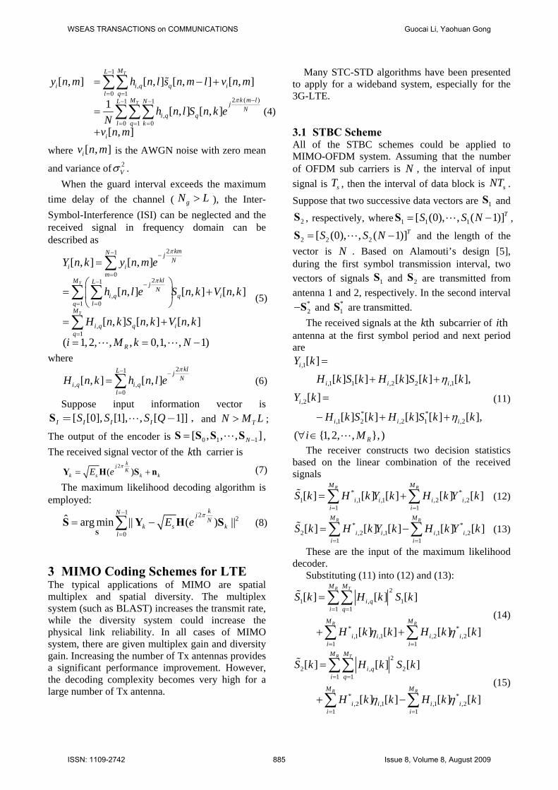
Fig 7 compare of SFTC and SFBC(2×2)
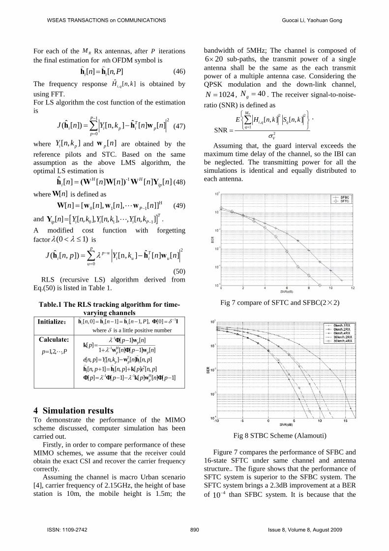
Fig 8 STBC Scheme (Alamouti)
Figure 7 compares the performance of SFBC and
16-state SFTC under same channel and antenna structure.. The figure shows that the performance of SFTC system is superior to the SFBC system. The SFTC system brings a 2.3dB improvement at a BER of 410− than SFBC system. It is because that the
WSEAS TRANSACTIONS on COMMUNICATIONS Guocai Li, Yaohuan Gong
ISSN: 1109-2742 890 Issue 8, Volume 8, August 2009
carefully designed SFTC can offer both diversity gain and coding gain, with the cost of the increasing of the decoding complexity.
Figure 8 shows the impact of fast fading channel on STBC-OFDM. It assumed that the channel keeps constant over 2 successive STBC-OFDM symbols. The performance of a system with the velocity of 30km/h is worse than the system of constant channel by 1~2dB loss. This is because that the fast fading of channel destroys the orthogonal of Alamouti scheme.
The fast fading could offer an extra diversity gain: Doppler diversity. To obtain the Doppler gain, much work had to be done with the channel estimating and decoding processing.
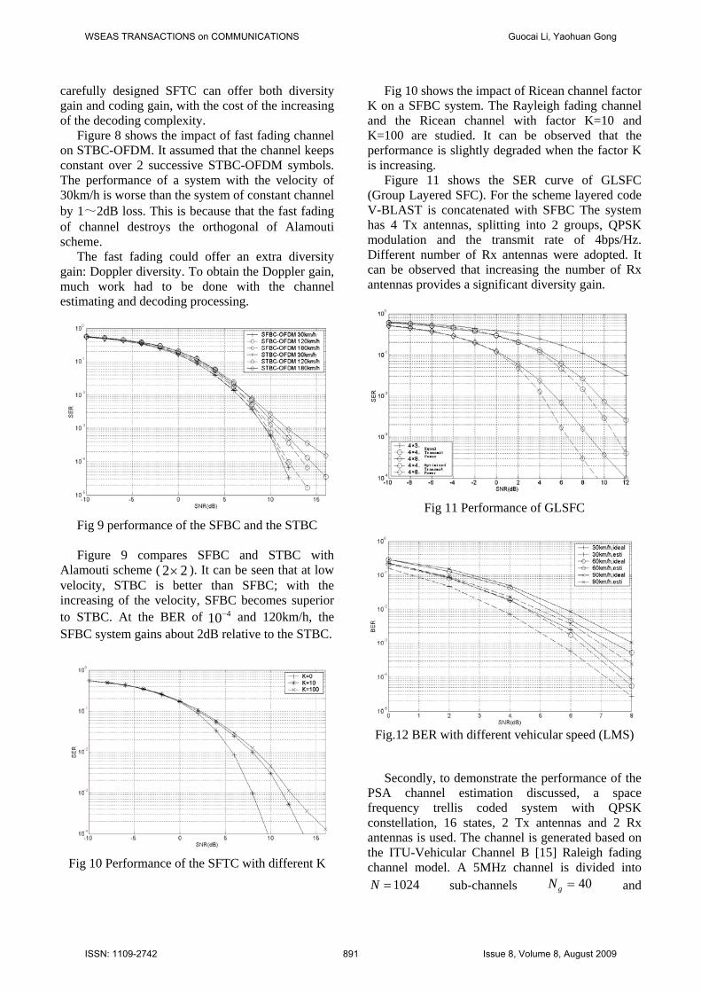
Fig 9 performance of the SFBC and the STBC Figure 9 compares SFBC and STBC with
Alamouti scheme ( 2 2× ). It can be seen that at low velocity, STBC is better than SFBC; with the increasing of the velocity, SFBC becomes superior to STBC. At the BER of 410− and 120km/h, the SFBC system gains about 2dB relative to the STBC.
Fig 10 Performance of the SFTC with different K
Fig 10 shows the impact of Ricean channel factor K on a SFBC system. The Rayleigh fading channel and the Ricean channel with factor K=10 and K=100 are studied. It can be observed that the performance is slightly degraded when the factor K is increasing.
Figure 11 shows the SER curve of GLSFC (Group Layered SFC). For the scheme layered code V-BLAST is concatenated with SFBC The system has 4 Tx antennas, splitting into 2 groups, QPSK modulation and the transmit rate of 4bps/Hz. Different number of Rx antennas were adopted. It can be observed that increasing the number of Rx antennas provides a significant diversity gain.
Fig 11 Performance of GLSFC
Fig.12 BER with different vehicular speed (LMS)
Secondly, to demonstrate the performance of the
PSA channel estimation discussed, a space frequency trellis coded system with QPSK constellation, 16 states, 2 Tx antennas and 2 Rx antennas is used. The channel is generated based on the ITU-Vehicular Channel B [15] Raleigh fading channel model. A 5MHz channel is divided into
1024N = sub-channels 40gN = and
WSEAS TRANSACTIONS on COMMUNICATIONS Guocai Li, Yaohuan Gong
ISSN: 1109-2742 891 Issue 8, Volume 8, August 2009

2150cf = MHz. It is assumed that there are 40tD = OFDM symbols in each frame.
Fig.13 BER with different vehicular speed (RLS)
Fig.12 and Fig.13 shows the Bit Error Rate (BER)
of the system with the LMS and RLS channel tracking approach. In each information OFDM symbol, 64 reference pilots are used for the LMS-Like tracking algorithm with 0.02μ = , 6L = and the RLS tracking algorithm with 0.99λ = and 6L = . The spectral efficiency loss is 8.6%. There is about 1dB SNR gap for the systems using the ideal and estimated channel coefficients with different Doppler frequency (60Hz, 120Hz, and 180Hz). For estimating one parameter of ,
ˆ [ , ]i qH n k ,
[ ]( )22 2 logPL N N N+ complex multiplication per parameter are required, which is 5.744/parameter. Among them, only 0.744 complex multiplication/parameter is consumed by the adaptive algorithm and the remaining are for the basic processing required by all the FFT assisted channel estimation schemes.
Fig.14 BER versus SNR with different L (LMS
30km/h)
Fig.15 Comparison of PSA-Interpolation, LMS and
RLS
Fig.14 illustrates the BER performance with different L when LMS algorithm is employed and the vehicular speed is 30km/h. The real channel used in the simulation has 3 paths. L is selected to be 2, 3, 6 and 9. It indicates that the path number of STC is different from the real will cause performance degradation. And STC without enough effective paths ( L =2) is worse that STC with overfull path ( L =9).
In Fig.15 shows a comparison of LMS and RLS channel tracking and PSA-interpolation. L is set to 6. For the PSA-Interpolation, 4fD = and 5tD = , and 1st order interpolation is used. Its spectral efficiency loss is 10%. For LMS ( 0.02μ = ) and RLS( 0.99λ = ), 40tD = and 64P = . The spectral losses are 8.6% for both the cases. It indicates that the three schemes have almost the same performance in BER. However, the two adaptive schemes have higher spectral efficiency and are more attractive to systems with large transmitter arrays. 5 Conclusion
In this paper, we discussed the combination of MIMO schemes for the downlink channel in 3G Long-Term Evolution (3G-LTE). The coding and decoding schemes in a time-variable multipath environment are discussed. In particular, the STBC/SFBC, SFTC/STTC and Group layered SFC coding-decoding schemes, were taken into account. Their performance including the computation complexity, frequency efficiency, BER and the effects of channel estimation, are compared. Furthermore, computer simulation results for these
WSEAS TRANSACTIONS on COMMUNICATIONS Guocai Li, Yaohuan Gong
ISSN: 1109-2742 892 Issue 8, Volume 8, August 2009

schemes. We believe that results will provide beneficial information to design MIMO scheme for the 3G-LTE downlink.
6 Acknowledgement The authors wish to grateful to their colleagues at Group of Smart Antenna and Signal Processing of UESTC. References: [1] H. Bolcskei, M.Boromann and A.J.Paulraj,
Impact of the propagation environment on the performance of space-frequency coded MIMO-OFDM, IEEE JSAC. Vol.21, No.3, pp.427-439, April 2003
[2] Z.Chen, B.Vucetic, J.Yuan, et al, Space-Time Trellis Codes with Two, Three and Four Transit Antennas in Quasi-Static Flat Fading Channels,IEEE ICC, vol 3,pp.1589-1595, May 2002
[3] V. Tarokh, et al, Combined array processing and space-time coding, IEEE Trans. on Inf. Theory, Vol. 45, No. 4, pp. 1121–1128, May 1999.
[4] 3rd Generation Partnership Project; Technical Specification Group Radio Access Network; Spatial Channel Model for Multiple Input Multiple Output (MIMO) simulations. 2003. www.3gpp.org
[5] S. M. Alamouti, A simple transmit diversity technique for wireless communications, IEEE J. Select. Areas Comm., Vol. 16, No. 8, pp. 1451-1458, Oct. 1998.
[6] G.J.Foschini, Layered space-time architecture for wireless communication in fading environment when using multi-element antennas, Bell Labs Tech.J. Vol.1, pp.41-59, 1996
[7] H. Bolcskei, M.Boromann and A.J.Paulraj, Impact of the propagation environment on the performance of space-frequency coded MIMO-OFDM, IEEE JSAC. Vol.21, No.3, pp.427-439, April 2003
[8] M.Hsieh and C.Wei, Channel estimation for OFDM systems based on Comb-Type Pilot Arrangement in Frequency Selective Fading Channels, pp.217-225, IEEE 1998
[9] Y(G). Li, Pilot-Symbol-Aided Channel Estimation for OFDM in Wireless Systems, IEEE Trans. On Vehicular Tech., Vol.49, No.4, pp.1207-1215, July 2000
[10] H.Minn and V.Bhargava, An investigation into Time-Domain Approach for OFDM Channel
Estimation, IEEE Trans. On Broadcasting, Vol. 46, No.4, pp.240-248, Dec.2000
[11] S.Kang, Y.Ha and K.Joo, A Comparative Investigation on Channel Estimation Algorithms for OFDM in Mobile Communications, IEEE Trans. On Broadcasting, Vol.49, No.2, pp.142-149, Jun.2003
[12] P.Hoeher, S.Kaiser and P.Robertson, Two-dimension pilot-symbol-aided channel estimation by wiener filtering, in Proc. 1997 IEEE Int. Conf. Acoustics, Speech, and Signal Processing, Munich, Germany, Apr.1997, pp.90-96
[13] King F.Lee and Douglas B.Williamos, “Pilot-Symbol-Assisted Channel Estimation for Space-Time Coded OFDM Systems,” EURASIP Journal on Applied Signal Processing 2002:5,507-516
[14] Y. (G.) Li, Simplified Channel Estimation for OFDM Systems With Multiple Transmit Antennas”, IEEE Trans.On Wireless Commum, vol. 1, pp.67-75, Jan.2002
[15] “Evaluation Methodology for IMT-2000 Radio Transmission Technologies”, http://www.arib.or.jp/
[16] 3GPP, “Physical layer aspects for evolved Universal Terrestrial Radio Access (UTRA) (Release 7),” TR 25.814 V7.1.0, Sept. 2006. [online]
WSEAS TRANSACTIONS on COMMUNICATIONS Guocai Li, Yaohuan Gong
ISSN: 1109-2742 893 Issue 8, Volume 8, August 2009