Embed Size (px)
Citation preview
STUDY THE VIBRATION OF THE AC DIPOLE AND MAGNETIC MEASUREMENT GIRDER FOR CSNS/RCS *
Liu Renhong, Qu Huamin, Kang Ling, Zhang Junsong, Wang Guangyuan Wang Haijing, IHEP, Beijing, China
Abstract The dipole magnet of the China Spallation Neutron
Source Rapid-cycling Synchrotron (RCS) will be operated at a 25 Hz sinusoidal alternating current which causes severe vibration. The vibration will influence the long-term safety and reliable operation of the magnet. By taking the magnet and magnetic measurement girder as a specific model system, a method for analysing and studying the dynamic characteristic of the system is put forward by combining theoretical calculation with experimental testing. And the active vibration of magnet is different with passive vibration which was causes by ground vibration, so a new isolator was designed to decrease the vibratory force and avoid the resonance phenomenon.
INTRODUCTION The CSNS-I accelerators consist of an 80 MeV H- linac
and a rapid cycling synchrotron of 1.6 GeV [1]. The RCS ring is a four-folded symmetrical topological structure which consist four arc zones and four line segments. There are 24 sets dipoles uniformly distributed in the whole RCS ring, and the AC dipoles will be operated at a 25 Hz rate sinusoidal alternating current. The magnetic core and coils made severe vibration especially at the frequency 25 Hz. At the same time the vibration influenced other equipment through the magnetic measurement girder.
Dipole magnet girder system with complex structure and high-precision adjustment is one of the most important equipment of the CSNS/RCS. Because of the self-excited vibration, the comprehensive technical index of requirement is different than other accelerator which vibration was caused by the ground vibration [2, 3]. So it is necessary to study the dynamic characteristic and reduce the vibration of the system [4]. After that a new isolator was designed to improve the dynamic characteristic of the system, decrease the vibratory force and avoid the resonance phenomenon. This paper adopts the AC dipole & magnetic measurement girder system as research object. The theoretical and testing methods are used to study the dynamic characteristic of the system.
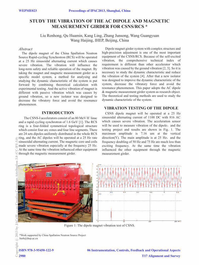
VIBRATION TESTING OF THE DIPOLE CSNS dipole magnet will be operated at a 25 Hz
sinusoidal alternating current of 1100 DC with 816 AC which causes severe vibration. The acceleration sensor will be used to measure vibration of the dipole and the testing project and results are shown in Fig. 1. The maximum amplitude is 7.16 um at the vertical direction(Y). The main amplitude is at 25 Hz and the frequency doubling of 50 Hz and 75 Hz are much less than exciting frequency. At the same time the vibration influenced the other equipment through the magnetic measurement girder.
Figure 1: The dipole magnet vibration test of CSNS.
___________________________________________
*Work supported by China Spallation Neutron Source Project [email protected]
Sensor
X
Y
ZDipole
Magnetic Measurement Girder
WEPME023 Proceedings of IPAC2013, Shanghai, China
ISBN 978-3-95450-122-9
2980Cop
yrig
htc ○
2013
byJA
CoW
—cc
Cre
ativ
eC
omm
onsA
ttri
butio
n3.
0(C
C-B
Y-3.
0)
06 Instrumentation, Controls, Feedback and Operational Aspects
T17 Alignment and Survey
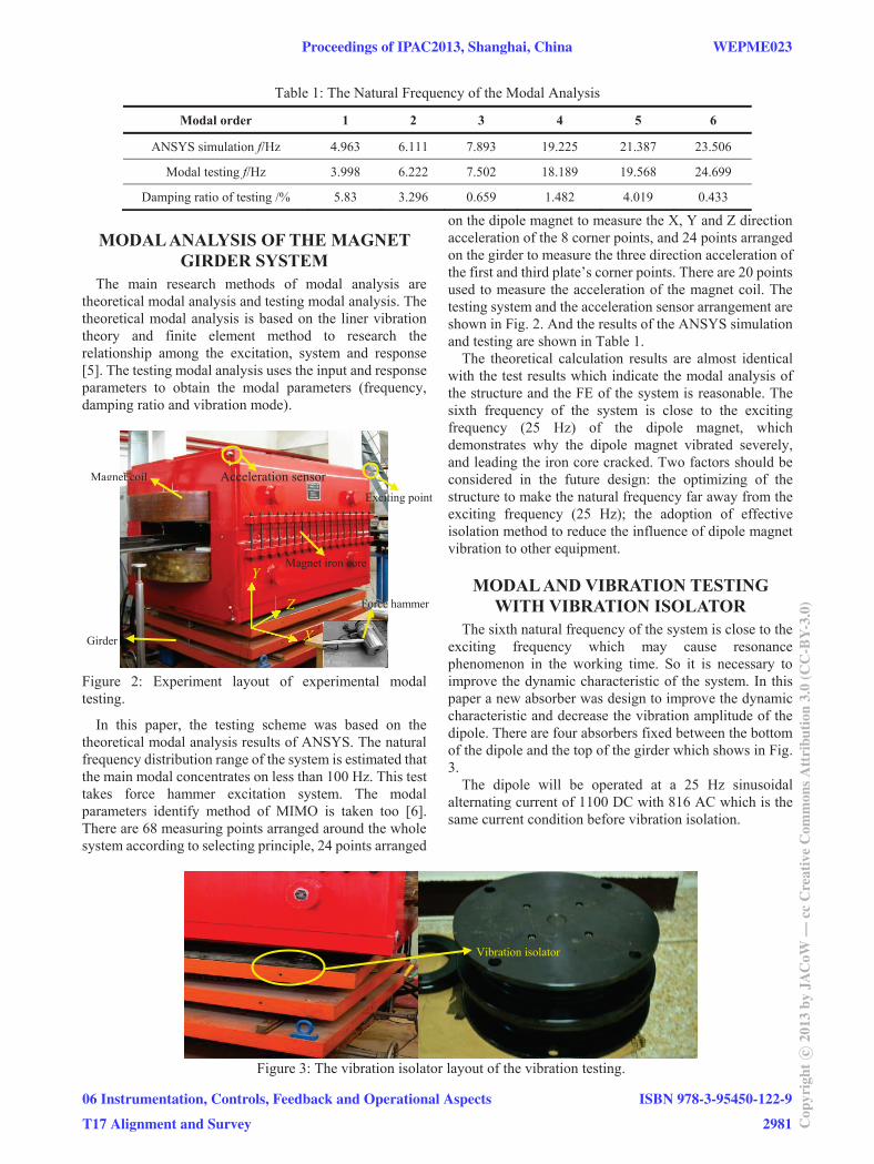
Table 1: The Natural Frequency of the Modal Analysis
Modal order 1 2 3 4 5 6
ANSYS simulation f/Hz 4.963 6.111 7.893 19.225 21.387 23.506
Modal testing f/Hz 3.998 6.222 7.502 18.189 19.568 24.699
Damping ratio of testing /% 5.83 3.296 0.659 1.482 4.019 0.433
MODAL ANALYSIS OF THE MAGNET GIRDER SYSTEM
The main research methods of modal analysis are theoretical modal analysis and testing modal analysis. The theoretical modal analysis is based on the liner vibration theory and finite element method to research the relationship among the excitation, system and response [5]. The testing modal analysis uses the input and response parameters to obtain the modal parameters (frequency, damping ratio and vibration mode).
Figure 2: Experiment layout of experimental modal testing.
In this paper, the testing scheme was based on the theoretical modal analysis results of ANSYS. The natural frequency distribution range of the system is estimated that the main modal concentrates on less than 100 Hz. This test takes force hammer excitation system. The modal parameters identify method of MIMO is taken too [6]. There are 68 measuring points arranged around the whole system according to selecting principle, 24 points arranged
on the dipole magnet to measure the X, Y and Z direction acceleration of the 8 corner points, and 24 points arranged on the girder to measure the three direction acceleration of the first and third plate’s corner points. There are 20 points used to measure the acceleration of the magnet coil. The testing system and the acceleration sensor arrangement are shown in Fig. 2. And the results of the ANSYS simulation and testing are shown in Table 1.
The theoretical calculation results are almost identical with the test results which indicate the modal analysis of the structure and the FE of the system is reasonable. The sixth frequency of the system is close to the exciting frequency (25 Hz) of the dipole magnet, which demonstrates why the dipole magnet vibrated severely, and leading the iron core cracked. Two factors should be considered in the future design: the optimizing of the structure to make the natural frequency far away from the exciting frequency (25 Hz); the adoption of effective isolation method to reduce the influence of dipole magnet vibration to other equipment.
MODAL AND VIBRATION TESTING WITH VIBRATION ISOLATOR
The sixth natural frequency of the system is close to the exciting frequency which may cause resonance phenomenon in the working time. So it is necessary to improve the dynamic characteristic of the system. In this paper a new absorber was design to improve the dynamic characteristic and decrease the vibration amplitude of the dipole. There are four absorbers fixed between the bottom of the dipole and the top of the girder which shows in Fig. 3.
The dipole will be operated at a 25 Hz sinusoidal alternating current of 1100 DC with 816 AC which is the same current condition before vibration isolation.
Figure 3: The vibration isolator layout of the vibration testing.
Acceleration sensor Exciting point
Force hammer
Girder
Magnet coil
Magnet iron core
Z
X
Y
Vibration isolator
Proceedings of IPAC2013, Shanghai, China WEPME023
06 Instrumentation, Controls, Feedback and Operational Aspects
T17 Alignment and Survey
ISBN 978-3-95450-122-9
2981 Cop
yrig
htc ○
2013
byJA
CoW
—cc
Cre
ativ
eC
omm
onsA
ttri
butio
n3.
0(C
C-B
Y-3.
0)
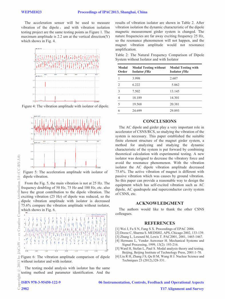
The acceleration sensor will be used to measure vibration of the dipole and with vibration isolation testing project are the same testing points as Figure 1. The maximum amplitude is 2.2 um at the vertical direction(Y) which shows in Fig. 4.
Figure 4: The vibration amplitude with isolator of dipole.
Figure 5: The acceleration amplitude with isolator of dipole vibration.
From the Fig. 5, the main vibration is not at 25 Hz. The frequency doubling of 50 Hz, 75 Hz and 100 Hz, etc. also have the great contribution to the dipole vibration. The exciting vibration (25 Hz) of dipole was reduced, so the dipole vibration amplitude with isolator is decreased 75.6% compare the vibration amplitude without isolator, which shows in Fig. 6.
Figure 6: The vibration amplitude comparison of dipole without isolator and with isolator.
The testing modal analysis with isolator has the same testing method and parameter identification. And the
results of vibration isolator are shown in Table 2. After vibration isolation the dynamic characteristic of the dipole magnetic measurement girder system is changed. The nature frequencies are far away exciting frequency 25 Hz, so the resonance phenomenon will not happen, and the magnet vibration amplitude would not resonance amplification. Table 2: The Natural Frequency Comparison of Dipole System without Isolator and with Isolator
Modal Order
Modal Testing without Isolator f/Hz
Modal Testing with Isolator f/Hz
1 3.998 2.607
2 6.222 5.062
3 7.502 13.145
4 18.189 14.301
5 19.568 20.381
6 24.699 29.893
CONCLUSIONS The AC dipole and girder play a very important role in
accelerator of CSNS/RCS, so studying the vibration of the system is necessary. This paper established the suitable finite element structure of the magnet girder system, a method for analyzing and studying the dynamic characteristic of the system is put forward by combining theoretical calculation with experimental testing. A new isolator was designed to decrease the vibratory force and avoid the resonance phenomenon. With the vibration isolator the AC dipole vibration amplitude decreased 75.6%. The active vibration of magnet is different with passive vibration which was causes by ground vibration. So this paper can provide a reasonable way to design the equipment which has self-excited vibration such as AC dipole, AC quadrupole and superconductor cavity system of CSNS, etc.
ACKNOWLEDGMENT The authors would like to thank the other CSNS
colleagues.
REFERENCES [1] Wei J, Fu S N, Fang S X. Proceedings of EPAC 2006. [2] Doose C, Sharma S. MEDSI02, APS, Chicago 2002, 133-139. [3] Zhang L, Lesourd M, Lewis T. PAC2001, 2001, 1465-1467. [4] Hermans L, Vender Auweraer H. Mechanical Systems and
Signal Processing, 1999, 13(2): 193-216. [5] Ward H, Stefan L, Paul S. Modal analysis theory and testing.
Beijing, Beijing Institute of Technology Press, 2001:1-70. [6] Liu R H, Zhang J S, Qu H M, Wang H J. Nuclear Science and
Techniques 23 (2012),328-331.
WEPME023 Proceedings of IPAC2013, Shanghai, China
ISBN 978-3-95450-122-9
2982Cop
yrig
htc ○
2013
byJA
CoW
—cc
Cre
ativ
eC
omm
onsA
ttri
butio
n3.
0(C
C-B
Y-3.
0)
06 Instrumentation, Controls, Feedback and Operational Aspects
T17 Alignment and Survey