Embed Size (px)
Citation preview
International Research Journal of Engineering and Technology (IRJET) e-ISSN: 2395 -0056
Volume: 03 Issue: 03 | Mar-2016 www.irjet.net p-ISSN: 2395-0072
© 2016, IRJET | Impact Factor value: 4.45 | ISO 9001:2008 Certified Journal | Page 731
Study of Speed and Torque Characteristics of MATLAB-Simulink
Designed PMSM: A Review
Bibhu Prasad Ganthia1 Samprati Mohanty1 Smita Aparajita Pattanaik2 Prashanta Kumar Rana3
1Electrical Engineering, Indira Gandhi Institute of Technology, Sarang,Dhenkanal,Odisha, India
2Electrical Engineering, VSSUT, Burla, Odisha,India
3Department of Electrical Science, Indian Institute of Technology, Bhubaneswar, Odisha, India
----------------------------------------------------------------------------------------------------------------------
Abstract—Permanent Magnet Synchronous Motors (PMSM)are widely used in robotic and industrial applications due to their low inertia, high efficiency and high torque – to -volume ratio. This paper proposes dynamic simulation models of PMSM with the aid of MATLAB – Simulink. The modeling procedures are described and simulation results are presented. These dynamic models capable of predicting the machine’s behavior for this machine type. All simulation results are presented for all machine’s variable characteristics. The validity of our model here is verified using V/f control, at various frequencies values. These models will be used in future, insensor less speed control.
Keywords—PM Synchronous Motor, Magnetic flux, speed-toque, MATLAB – Simulink and dynamic modeling
Introduction Since the last three decades AC machine drives
are becoming more popular, especially Induction
Motor (IM) and Permanent Magnet Synchronous
Motor, but with some special characteristics, the
PMSM drives are ready to meet up sophisticated
needs such as fast dynamic response, high power
factor, and wide operating speed range, as a result, a
gradual gain in the use of PMSM drives will surely be
witness in the future in low and mid power
applications. In a PMSM, the dc field winding of the
rotor is replaced by a permanent magnet to produce
the air-gap magnetic flux. Having the magnets on
the rotor, electrical losses due to field winding of
the machine get reduced and the lack of the field
losses improves the thermal characteristics of the
PM machines and its efficiency. Absence of
mechanical components like brushes and slip rings
makes the motor lighter, high power to weight ratio
for which a higher efficiency and reliability is
achieved.
II. MATHEMATICAL MODEL OF PMSM
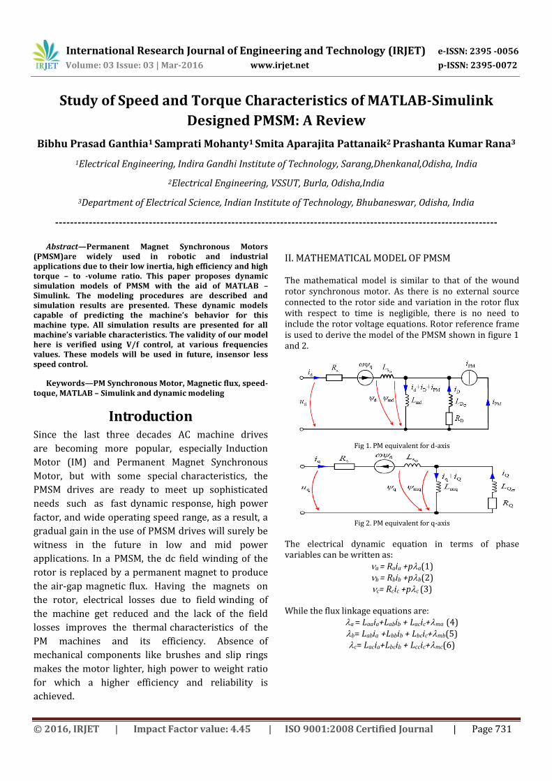
The mathematical model is similar to that of the wound rotor synchronous motor. As there is no external source connected to the rotor side and variation in the rotor flux with respect to time is negligible, there is no need to include the rotor voltage equations. Rotor reference frame is used to derive the model of the PMSM shown in figure 1 and 2.
Fig 1. PM equivalent for d-axis
Fig 2. PM equivalent for q-axis
The electrical dynamic equation in terms of phase variables can be written as:
a = Raia +pa(1) b = Rbib +pb(2) c= Rcic +pc (3)
While the flux linkage equations are:
a = Laaia+Labib + Lacic+ma (4) b= Labia +Lbbib + Lbcic+mb(5) c= Lacia+Lbcib + Lccic+mc(6)
International Research Journal of Engineering and Technology (IRJET) e-ISSN: 2395 -0056
Volume: 03 Issue: 03 | Mar-2016 www.irjet.net p-ISSN: 2395-0072
© 2016, IRJET | Impact Factor value: 4.45 | ISO 9001:2008 Certified Journal | Page 732
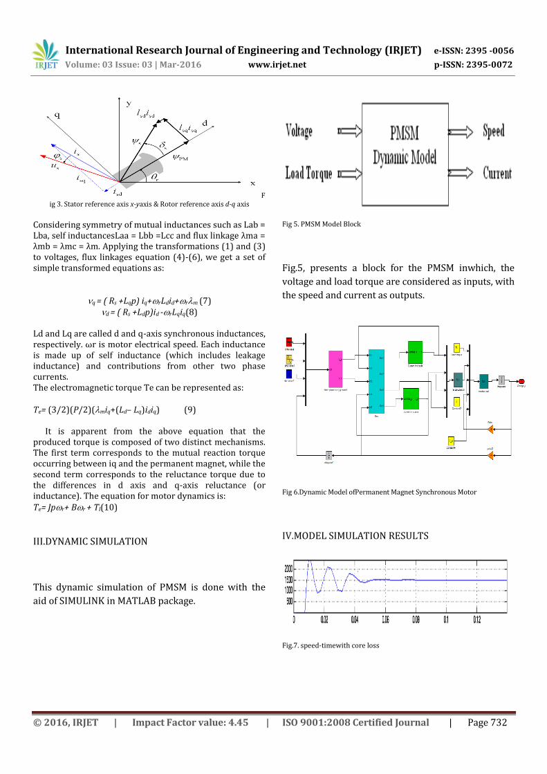
Fig 3. Stator reference axis x-yaxis & Rotor reference axis d-q axis
Considering symmetry of mutual inductances such as Lab = Lba, self inductancesLaa = Lbb =Lcc and flux linkage λma = λmb = λmc = λm. Applying the transformations (1) and (3) to voltages, flux linkages equation (4)-(6), we get a set of simple transformed equations as:
q = ( Rs +Lqp) iq+rLdid+rm (7)
d = ( Rs +Ldp)id -rLqiq(8) Ld and Lq are called d and q-axis synchronous inductances, respectively. ωr is motor electrical speed. Each inductance is made up of self inductance (which includes leakage inductance) and contributions from other two phase currents. The electromagnetic torque Te can be represented as: Te= (3/2)(P/2)(miq+(Ld– Lq)idiq) (9) It is apparent from the above equation that the produced torque is composed of two distinct mechanisms. The first term corresponds to the mutual reaction torque occurring between iq and the permanent magnet, while the second term corresponds to the reluctance torque due to the differences in d axis and q-axis reluctance (or inductance). The equation for motor dynamics is: Te= Jpr+ Br + Tl(10)
III.DYNAMIC SIMULATION
This dynamic simulation of PMSM is done with the
aid of SIMULINK in MATLAB package.
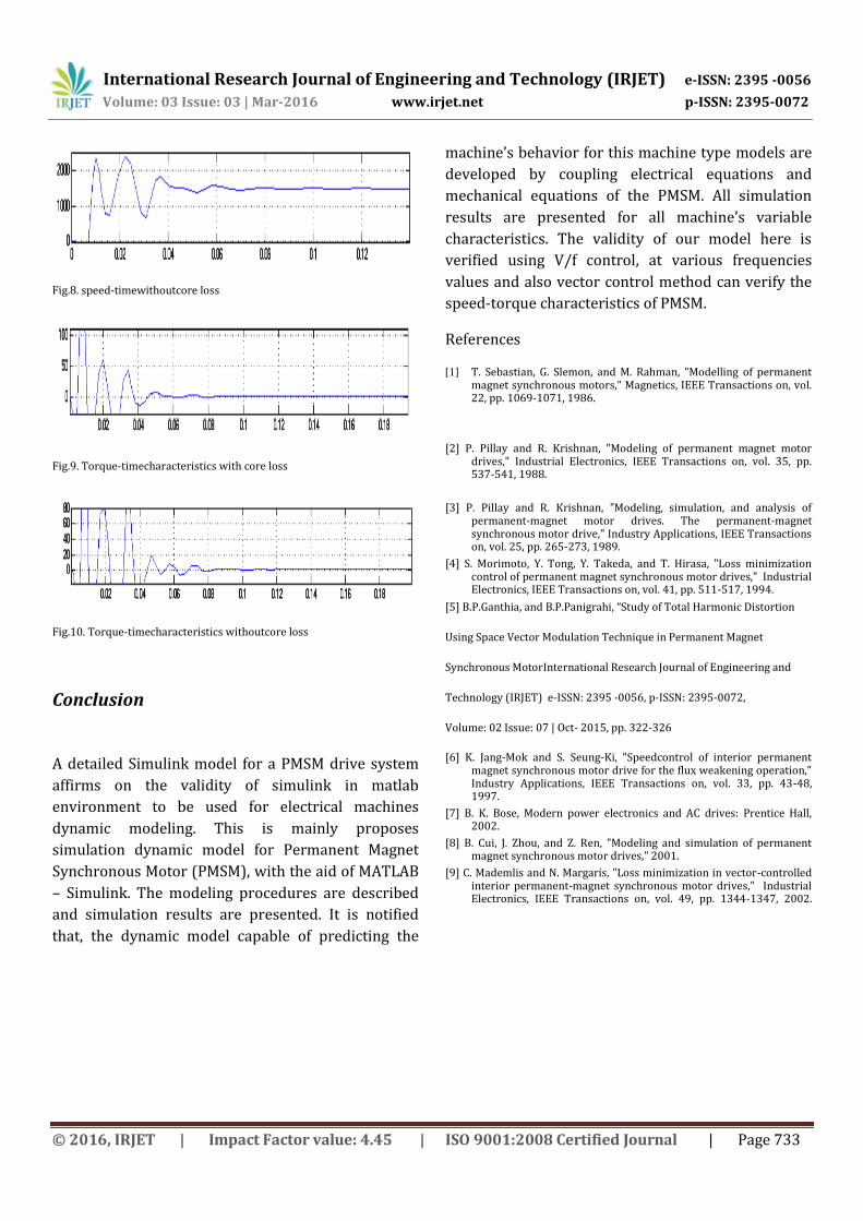
Fig 5. PMSM Model Block
Fig.5, presents a block for the PMSM inwhich, the
voltage and load torque are considered as inputs, with
the speed and current as outputs.
Fig 6.Dynamic Model ofPermanent Magnet Synchronous Motor
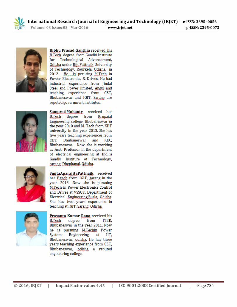
IV.MODEL SIMULATION RESULTS
Fig.7. speed-timewith core loss
International Research Journal of Engineering and Technology (IRJET) e-ISSN: 2395 -0056
Volume: 03 Issue: 03 | Mar-2016 www.irjet.net p-ISSN: 2395-0072
© 2016, IRJET | Impact Factor value: 4.45 | ISO 9001:2008 Certified Journal | Page 733
Fig.8. speed-timewithoutcore loss
Fig.9. Torque-timecharacteristics with core loss
Fig.10. Torque-timecharacteristics withoutcore loss
Conclusion
A detailed Simulink model for a PMSM drive system
affirms on the validity of simulink in matlab
environment to be used for electrical machines
dynamic modeling. This is mainly proposes
simulation dynamic model for Permanent Magnet
Synchronous Motor (PMSM), with the aid of MATLAB
– Simulink. The modeling procedures are described
and simulation results are presented. It is notified
that, the dynamic model capable of predicting the
machine’s behavior for this machine type models are
developed by coupling electrical equations and
mechanical equations of the PMSM. All simulation
results are presented for all machine’s variable
characteristics. The validity of our model here is
verified using V/f control, at various frequencies
values and also vector control method can verify the
speed-torque characteristics of PMSM.
References
[1] T. Sebastian, G. Slemon, and M. Rahman, "Modelling of permanent magnet synchronous motors," Magnetics, IEEE Transactions on, vol. 22, pp. 1069-1071, 1986.
[2] P. Pillay and R. Krishnan, "Modeling of permanent magnet motor drives," Industrial Electronics, IEEE Transactions on, vol. 35, pp. 537-541, 1988.
[3] P. Pillay and R. Krishnan, "Modeling, simulation, and analysis of permanent-magnet motor drives. The permanent-magnet synchronous motor drive," Industry Applications, IEEE Transactions on, vol. 25, pp. 265-273, 1989.
[4] S. Morimoto, Y. Tong, Y. Takeda, and T. Hirasa, "Loss minimization control of permanent magnet synchronous motor drives," Industrial Electronics, IEEE Transactions on, vol. 41, pp. 511-517, 1994.
[5] B.P.Ganthia, and B.P.Panigrahi, “Study of Total Harmonic Distortion
Using Space Vector Modulation Technique in Permanent Magnet
Synchronous MotorInternational Research Journal of Engineering and
Technology (IRJET) e-ISSN: 2395 -0056, p-ISSN: 2395-0072,
Volume: 02 Issue: 07 | Oct- 2015, pp. 322-326
[6] K. Jang-Mok and S. Seung-Ki, "Speedcontrol of interior permanent magnet synchronous motor drive for the flux weakening operation," Industry Applications, IEEE Transactions on, vol. 33, pp. 43-48, 1997.
[7] B. K. Bose, Modern power electronics and AC drives: Prentice Hall, 2002.
[8] B. Cui, J. Zhou, and Z. Ren, "Modeling and simulation of permanent magnet synchronous motor drives," 2001.
[9] C. Mademlis and N. Margaris, "Loss minimization in vector-controlled interior permanent-magnet synchronous motor drives," Industrial Electronics, IEEE Transactions on, vol. 49, pp. 1344-1347, 2002.
International Research Journal of Engineering and Technology (IRJET) e-ISSN: 2395 -0056
Volume: 03 Issue: 03 | Mar-2016 www.irjet.net p-ISSN: 2395-0072
© 2016, IRJET | Impact Factor value: 4.45 | ISO 9001:2008 Certified Journal | Page 734