Embed Size (px)
Citation preview
University of HelsinkiDepartment of Computer ScienceSeries of Publications C, No. C-2012-4
Study of Middle-box Behavior on Transport Layer Protocols
Seppo Hatonen, Yonghao Li, Markku Kojo
Helsinki, June 13, 2012
Technical Report C-2012-4
University of HelsinkiDepartment of Computer ScienceP. O. Box 68 (Gustaf Hallstromin katu 2b)FIN-00014 University of Helsinki, FINLAND
Study of Middle-box Behavior on Transport Layer Protocols
Seppo Hatonen, Yonghao Li, Markku KojoDepartment of Computer Science, University of HelsinkiTechnical Report C-2012-4June 13, 201218 pages
Abstract. Today, the home gateways that act as middle-boxes between the internal network of a residential user or aSmall Office/Home Office (SOHO) and the public network or Internet are very common. These devices includewireless access points and cable and DSL modems. The devices perform various higher-layer functions suchas traffic filtering, network address translation (NAT) and can act as a dynamic host configuration protocol(DHCP) server. While some of these functions such as DHCP are well standardized, some functions such asNAT have only been defined on a more abstract level and the exact operation have not been standardized. Thesemore loosely defined functions are known to have undesired effects on normal protocol operation and hinderthe development of new protocols and applications. Therefore, it is important to understand what differentmiddle-boxes that have been deployed all around the world actually do and what are their characteristics. Thisexperimental study concentrates on the transport layer functionality of home gateways. The transport layeris responsible for the transport services such as provided by Transmission Control Protocol (TCP) and UserDatagram Protocol (UDP.) While some of the protocols are widely used and well-known, some newer protocolsand extensions to the earlier protocols might have difficulties with the middle-boxes. The NAT function isparticularly problematic since many newer protocols and extensions might not have been deployed when someof the middle-boxes were built and deployed. Due to this, the middle-boxes may not be able to properlyforward packets carrying these protocols and applications. We test new transport protocols such as LightweightUser Datagram Protocol (UDP-Lite) and Stream Control Transmission Protocol (SCTP), extensions to regularoperation such as inserting payload to the initial TCP SYN packet, and the UDP throughput performance of themiddle-boxes.
Contents
1 Introduction 1
2 Testbed Description 1
3 Experiments 4
3.1 UDPLite1,2: UDP-Lite Support . . . . . . . . . . . . . . . . . . . . . . . . . . . . . . . . 4
3.1.1 Test Description . . . . . . . . . . . . . . . . . . . . . . . . . . . . . . . . . . . . 4
3.1.2 Results . . . . . . . . . . . . . . . . . . . . . . . . . . . . . . . . . . . . . . . . . 5
3.2 DCCP1: DCCP Support . . . . . . . . . . . . . . . . . . . . . . . . . . . . . . . . . . . . 5
3.2.1 Test Description . . . . . . . . . . . . . . . . . . . . . . . . . . . . . . . . . . . . 5
3.2.2 Results . . . . . . . . . . . . . . . . . . . . . . . . . . . . . . . . . . . . . . . . . 6
3.3 SCTP1,2: SCTP Support . . . . . . . . . . . . . . . . . . . . . . . . . . . . . . . . . . . . 6
3.3.1 Test Description . . . . . . . . . . . . . . . . . . . . . . . . . . . . . . . . . . . . 6
3.3.2 Results . . . . . . . . . . . . . . . . . . . . . . . . . . . . . . . . . . . . . . . . . 6
3.4 UDP1-Sub1,2: TCP&UDP NAT mapping classification test . . . . . . . . . . . . . . . . . . 7
3.4.1 Test Description . . . . . . . . . . . . . . . . . . . . . . . . . . . . . . . . . . . . 7
3.4.2 Results . . . . . . . . . . . . . . . . . . . . . . . . . . . . . . . . . . . . . . . . . 8
3.5 UDP2: UDP NAT Filtering Classification . . . . . . . . . . . . . . . . . . . . . . . . . . . 9
3.5.1 Test Description . . . . . . . . . . . . . . . . . . . . . . . . . . . . . . . . . . . . 9
3.5.2 Results . . . . . . . . . . . . . . . . . . . . . . . . . . . . . . . . . . . . . . . . . 10
3.6 UDP3: UDP Throughput . . . . . . . . . . . . . . . . . . . . . . . . . . . . . . . . . . . . 10
3.6.1 Test Description . . . . . . . . . . . . . . . . . . . . . . . . . . . . . . . . . . . . 10
3.6.2 Results . . . . . . . . . . . . . . . . . . . . . . . . . . . . . . . . . . . . . . . . . 10
3.7 TCP1: Does NAT Devices Rewrite TCP Header Fields . . . . . . . . . . . . . . . . . . . . 12
3.7.1 Test Description . . . . . . . . . . . . . . . . . . . . . . . . . . . . . . . . . . . . 12
3.7.2 Results . . . . . . . . . . . . . . . . . . . . . . . . . . . . . . . . . . . . . . . . . 13
3.8 TCP2: Reserved Bits in the TCP Header . . . . . . . . . . . . . . . . . . . . . . . . . . . . 13
3.8.1 Test Description . . . . . . . . . . . . . . . . . . . . . . . . . . . . . . . . . . . . 13
3.8.2 Results . . . . . . . . . . . . . . . . . . . . . . . . . . . . . . . . . . . . . . . . . 14
3.9 TCP3: Does TCP RST Tear Down NAT Bindings . . . . . . . . . . . . . . . . . . . . . . . 14
3.9.1 Test Description . . . . . . . . . . . . . . . . . . . . . . . . . . . . . . . . . . . . 14
ii
3.9.2 Results . . . . . . . . . . . . . . . . . . . . . . . . . . . . . . . . . . . . . . . . . 14
3.10 TCP4: Does TCP SYN with Payload Go Through NAT Devices . . . . . . . . . . . . . . . 15
3.10.1 Test Description . . . . . . . . . . . . . . . . . . . . . . . . . . . . . . . . . . . . 15
3.10.2 Results . . . . . . . . . . . . . . . . . . . . . . . . . . . . . . . . . . . . . . . . . 15
3.11 TCP6: TCP Options in SYN Packets Handling . . . . . . . . . . . . . . . . . . . . . . . . 15
3.11.1 Test Description . . . . . . . . . . . . . . . . . . . . . . . . . . . . . . . . . . . . 15
3.11.2 Results . . . . . . . . . . . . . . . . . . . . . . . . . . . . . . . . . . . . . . . . . 15
3.12 TCP7: TCP Options in Data Packets Handling . . . . . . . . . . . . . . . . . . . . . . . . . 16
3.12.1 Test Description . . . . . . . . . . . . . . . . . . . . . . . . . . . . . . . . . . . . 16
3.12.2 Results . . . . . . . . . . . . . . . . . . . . . . . . . . . . . . . . . . . . . . . . . 17
4 Conclusions 17
5 Acknowledgements 17
iii
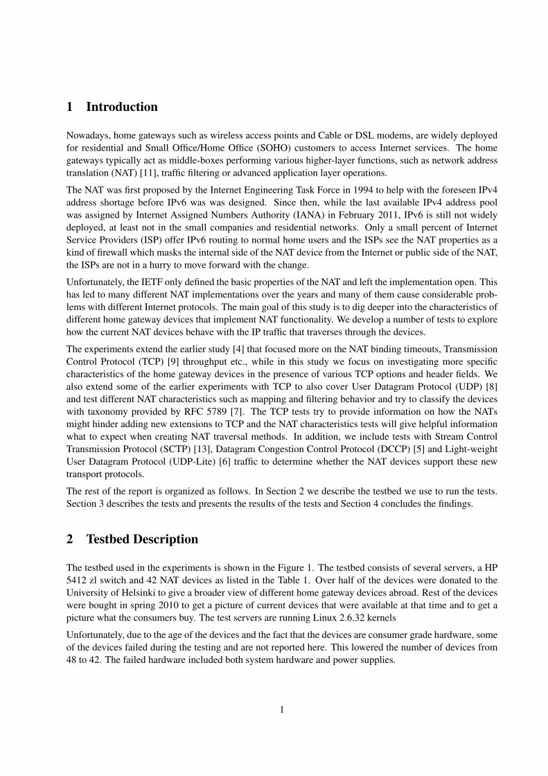
1 Introduction
Nowadays, home gateways such as wireless access points and Cable or DSL modems, are widely deployedfor residential and Small Office/Home Office (SOHO) customers to access Internet services. The homegateways typically act as middle-boxes performing various higher-layer functions, such as network addresstranslation (NAT) [11], traffic filtering or advanced application layer operations.
The NAT was first proposed by the Internet Engineering Task Force in 1994 to help with the foreseen IPv4address shortage before IPv6 was was designed. Since then, while the last available IPv4 address poolwas assigned by Internet Assigned Numbers Authority (IANA) in February 2011, IPv6 is still not widelydeployed, at least not in the small companies and residential networks. Only a small percent of InternetService Providers (ISP) offer IPv6 routing to normal home users and the ISPs see the NAT properties as akind of firewall which masks the internal side of the NAT device from the Internet or public side of the NAT,the ISPs are not in a hurry to move forward with the change.
Unfortunately, the IETF only defined the basic properties of the NAT and left the implementation open. Thishas led to many different NAT implementations over the years and many of them cause considerable prob-lems with different Internet protocols. The main goal of this study is to dig deeper into the characteristics ofdifferent home gateway devices that implement NAT functionality. We develop a number of tests to explorehow the current NAT devices behave with the IP traffic that traverses through the devices.
The experiments extend the earlier study [4] that focused more on the NAT binding timeouts, TransmissionControl Protocol (TCP) [9] throughput etc., while in this study we focus on investigating more specificcharacteristics of the home gateway devices in the presence of various TCP options and header fields. Wealso extend some of the earlier experiments with TCP to also cover User Datagram Protocol (UDP) [8]and test different NAT characteristics such as mapping and filtering behavior and try to classify the deviceswith taxonomy provided by RFC 5789 [7]. The TCP tests try to provide information on how the NATsmight hinder adding new extensions to TCP and the NAT characteristics tests will give helpful informationwhat to expect when creating NAT traversal methods. In addition, we include tests with Stream ControlTransmission Protocol (SCTP) [13], Datagram Congestion Control Protocol (DCCP) [5] and Light-weightUser Datagram Protocol (UDP-Lite) [6] traffic to determine whether the NAT devices support these newtransport protocols.
The rest of the report is organized as follows. In Section 2 we describe the testbed we use to run the tests.Section 3 describes the tests and presents the results of the tests and Section 4 concludes the findings.
2 Testbed Description
The testbed used in the experiments is shown in the Figure 1. The testbed consists of several servers, a HP5412 zl switch and 42 NAT devices as listed in the Table 1. Over half of the devices were donated to theUniversity of Helsinki to give a broader view of different home gateway devices abroad. Rest of the deviceswere bought in spring 2010 to get a picture of current devices that were available at that time and to get apicture what the consumers buy. The test servers are running Linux 2.6.32 kernels
Unfortunately, due to the age of the devices and the fact that the devices are consumer grade hardware, someof the devices failed during the testing and are not reported here. This lowered the number of devices from48 to 42. The failed hardware included both system hardware and power supplies.
1
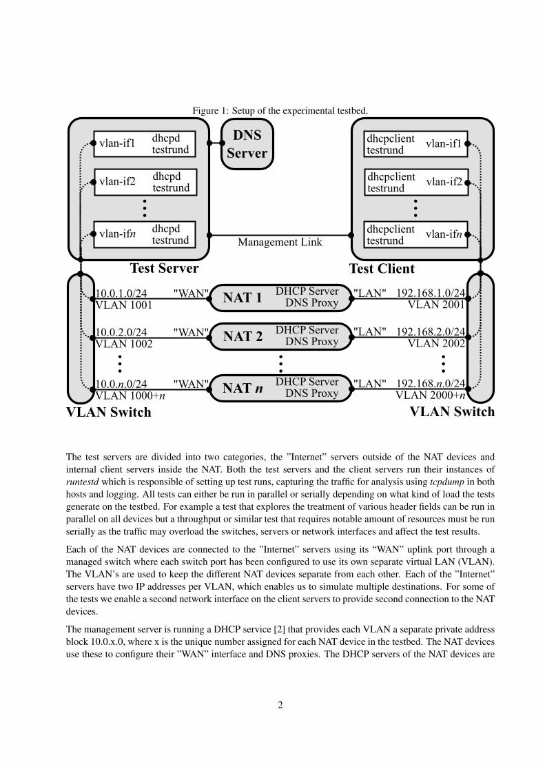
Figure 1: Setup of the experimental testbed.
NAT 1
NAT 2 ...
NAT n
VLAN Switch VLAN Switch
DHCP ServerDNS Proxy
DHCP ServerDNS Proxy
DHCP ServerDNS Proxy
10.0.1.0/24VLAN 1001
10.0.2.0/24VLAN 1002
10.0.n.0/24VLAN 1000+n
192.168.1.0/24VLAN 2001
192.168.2.0/24VLAN 2002
192.168.n.0/24VLAN 2000+n
Test Client
Management Linkdhcpclienttestrund
vlan-ifn
dhcpclienttestrund
vlan-if2
dhcpclienttestrund
vlan-if1
...
Test Server
dhcpdtestrund
vlan-ifn
dhcpdtestrund
vlan-if2
dhcpdtestrund
vlan-if1
...
DNSServer
... ...
"LAN"
"LAN"
"LAN"
"WAN"
"WAN"
"WAN"
The test servers are divided into two categories, the ”Internet” servers outside of the NAT devices andinternal client servers inside the NAT. Both the test servers and the client servers run their instances ofruntestd which is responsible of setting up test runs, capturing the traffic for analysis using tcpdump in bothhosts and logging. All tests can either be run in parallel or serially depending on what kind of load the testsgenerate on the testbed. For example a test that explores the treatment of various header fields can be run inparallel on all devices but a throughput or similar test that requires notable amount of resources must be runserially as the traffic may overload the switches, servers or network interfaces and affect the test results.
Each of the NAT devices are connected to the ”Internet” servers using its “WAN” uplink port through amanaged switch where each switch port has been configured to use its own separate virtual LAN (VLAN).The VLAN’s are used to keep the different NAT devices separate from each other. Each of the ”Internet”servers have two IP addresses per VLAN, which enables us to simulate multiple destinations. For some ofthe tests we enable a second network interface on the client servers to provide second connection to the NATdevices.
The management server is running a DHCP service [2] that provides each VLAN a separate private addressblock 10.0.x.0, where x is the unique number assigned for each NAT device in the testbed. The NAT devicesuse these to configure their ”WAN” interface and DNS proxies. The DHCP servers of the NAT devices are
2

Table 1: Home gateway models included in the study, with the shorthand “tags” used throughout this reportVendor Model Firmware TagA-Link WNAP e2.0.9A alApple Airport Express 7.4.2 apAsus RT-N15 2.0.1.1 as1
WL-500G Premium V2 3.0.3.5 as2
Belkin
Wireless N Router F5D8236-4 WW 3.00.02 be1Enhanced N150 F6D4230-4 WW 1.00.03 be2Wireless G Router F:3.00.03 H: F5D7234-4 v3 (01) be3Wireless G Plus MIMO Router F5D9230-4 ver. 3000 3.02.76 be4
Buffalo WZR-AGL300NH R1.06/B1.05 bu1
D-Link
DIR-300 1.03 dl1DIR-300 1.04 dl2DI-524up v1.06 dl3DI-524 v2.0.4 dl4DIR-100 v1.12 dl5DIR-600 v2.01 dl6DIR-615 v4.00 dl7DIR-635 v2.33EU dl8WBR-1310 1.04 dl11
Edimax 6104WG 2.63 edJensen Air:Link 59300 1.15 je
Linksys
BEFSR41c2 1.45.11 ls1W54G v7.00.1 ls2WRT54GL v1.1 v4.30.7 ls3WRT54GL-EU v4.30.7 ls5WRT54G OpenWRT RC5 owrtWRT54GL v1.1 tomato 1.27 to
Netgear
RP614 v4 V1.0.2 06.29 ng1WGR614 v7 (1.0.13 1.0.13) ng2WGR614 v9 V1.2.6 18.0.17 ng3WNR2000-100PES v.1.0.0.34 29.0.45 ng4WGR614 v6 V1.0.11 1.0.7 ng6WGR614 V1.40 Feb 18 2004 ng7WGT624 v4 V2.0.6 2.0.6NA ng8WGT624 v3 v2.0.25 1.0.1NA ng9MR314 V3.30(CF.0) ng10RP114 V3.26(cd.0) ng11
Netwjork 54M Ver 1.2.6 nw1SMC Barricade SMC7004VBR R1.07 smcTelewell TW-3G V7.04b3 teUnicom WEP-72104G rev. 2 v4.2.3.18.1e un1Webee Wireless N Router e2.0.9D weZyXel P-335U V3.60(AMB.2)C0 zy1
configured to distribute private address to clients from 192.168.x.0 blocks. The management server is alsorunning a NTP server that provides synchronised time to both test and client servers.
The majority of the NAT devices in the testbed provide a switch capability and one device, ap, has onlya wireless interface in addition to its “WAN” interface. Each of the NAT devices is connected to the testclient through one of the “LAN” interfaces. (The ap is connected to the client host through a separate USBWLAN dongle.) The client hosts have a separate DHCP client listening on each separate VLAN and setsthe interface with the information that the NAT device provides via its DHCP server. The DHCP client wasmodified to configure only the interface-specific routes and to not set up the default route.
3
3 Experiments
We mainly focus on exploring various NAT behavior in the transport layer (layer 4). As we know, theNAT devices in many cases cause problems with the normal protocol and application operation and makedeveloping new protocols difficult. Thus, the first tests (UDPLite1, DCCP1 and SCTP1,2) try to explorethe compatibility of the NAT devices with newer transport protocols, including Stream Control Transmis-sion Protocol (SCTP), Light-weight User Datagram Protocol (UDP-Lite) and Datagram Congestion ControlProtocol (DCCP). The following of tests focus on TCP specific NAT behavior, namely, what occurs to theTCP header fields and TCP options. The possible behavior of the NAT devices include dropping the packetswhich the NAT device does not understand, modifying the packet or just forwarding the packet to the re-ceiver. In addition, the instantaneous NAT behavior is difficult to observe. Thus, we include several tests thatemulate the specific functions of the Session Traversal Utilities for NAT (STUN) protocol [10] to map thediverse real-time NAT behavior with the UDP and TCP traffic. Especially, this allows the internal test clientto emulate specific STUN properties for the purpose of probing the behavior of the NAT devices betweenthe test client and the test server [7].
3.1 UDPLite1,2: UDP-Lite Support
3.1.1 Test Description
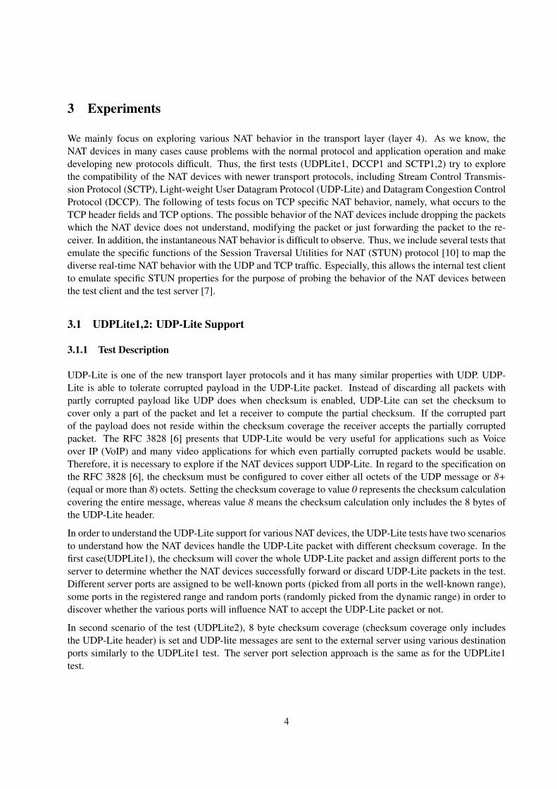
UDP-Lite is one of the new transport layer protocols and it has many similar properties with UDP. UDP-Lite is able to tolerate corrupted payload in the UDP-Lite packet. Instead of discarding all packets withpartly corrupted payload like UDP does when checksum is enabled, UDP-Lite can set the checksum tocover only a part of the packet and let a receiver to compute the partial checksum. If the corrupted partof the payload does not reside within the checksum coverage the receiver accepts the partially corruptedpacket. The RFC 3828 [6] presents that UDP-Lite would be very useful for applications such as Voiceover IP (VoIP) and many video applications for which even partially corrupted packets would be usable.Therefore, it is necessary to explore if the NAT devices support UDP-Lite. In regard to the specification onthe RFC 3828 [6], the checksum must be configured to cover either all octets of the UDP message or 8+(equal or more than 8) octets. Setting the checksum coverage to value 0 represents the checksum calculationcovering the entire message, whereas value 8 means the checksum calculation only includes the 8 bytes ofthe UDP-Lite header.
In order to understand the UDP-Lite support for various NAT devices, the UDP-Lite tests have two scenariosto understand how the NAT devices handle the UDP-Lite packet with different checksum coverage. In thefirst case(UDPLite1), the checksum will cover the whole UDP-Lite packet and assign different ports to theserver to determine whether the NAT devices successfully forward or discard UDP-Lite packets in the test.Different server ports are assigned to be well-known ports (picked from all ports in the well-known range),some ports in the registered range and random ports (randomly picked from the dynamic range) in order todiscover whether the various ports will influence NAT to accept the UDP-Lite packet or not.
In second scenario of the test (UDPLite2), 8 byte checksum coverage (checksum coverage only includesthe UDP-Lite header) is set and UDP-lite messages are sent to the external server using various destinationports similarly to the UDPLite1 test. The server port selection approach is the same as for the UDPLite1test.
4
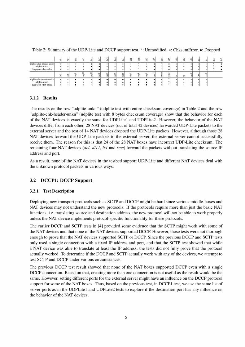
Table 2: Summary of the UDP-Lite and DCCP support test. o: Unmodified, ∗: ChksumError, •: Dropped
al ap as1
as2
be1
be2
be3
be4
bu1
dl1
dl11
dl2
dl3
dl4
dl5
dl6
dl7
dl8
ed je ls1
ls2
udplite-chk-header-unkn ∗ ∗ ∗ ∗ • • ∗ ∗ ∗ ∗ o ∗ • o • ∗ ∗ ∗ ∗ ∗ o •udplite-unkn ∗ ∗ ∗ ∗ • • ∗ ∗ ∗ ∗ o ∗ • o • ∗ ∗ ∗ ∗ ∗ o •
dccp-con-rdsp-unkn ∗ ∗ ∗ ∗ • • ∗ ∗ ∗ ∗ o ∗ • o • ∗ ∗ ∗ ∗ ∗ o •
ls3
ls5
ng1
ng10
ng11
ng2
ng3
ng4
ng6
ng7
ng8
ng9
nw1
owrt
smc
te to un1
we
zy1
udplite-chk-header-unkn ∗ ∗ • ∗ ∗ • • • • • • • • ∗ o ∗ ∗ ∗ ∗ ∗udplite-unkn ∗ ∗ • ∗ ∗ • • • • • • • • ∗ o ∗ ∗ ∗ ∗ ∗
dccp-con-rdsp-unkn ∗ ∗ • ∗ ∗ • • • • • • • • ∗ o ∗ ∗ ∗ ∗ ∗
3.1.2 Results
The results on the row ”udplite-unkn” (udplite test with entire checksum coverage) in Table 2 and the row”udplite-chk-header-unkn” (udplite test with 8 bytes checksum coverage) show that the behavior for eachof the NAT devices is exactly the same for UDPLite1 and UDPLite2. However, the behavior of the NATdevices differ from each other. 28 NAT devices (out of total 42 devices) forwarded UDP-Lite packets to theexternal server and the rest of 14 NAT devices dropped the UDP-Lite packets. However, although those 28NAT devices forward the UDP-Lite packets to the external server, the external server cannot successfullyreceive them. The reason for this is that 24 of the 28 NAT boxes have incorrect UDP-Lite checksum. Theremaining four NAT devices (dl4, dl11, ls1 and smc) forward the packets without translating the source IPaddress and port.
As a result, none of the NAT devices in the testbed support UDP-Lite and different NAT devices deal withthe unknown protocol packets in various ways.
3.2 DCCP1: DCCP Support
3.2.1 Test Description
Deploying new transport protocols such as SCTP and DCCP might be hard since various middle-boxes andNAT devices may not understand the new protocols. If the protocols require more than just the basic NATfunctions, i.e. translating source and destination address, the new protocol will not be able to work properlyunless the NAT device implements protocol-specific functionality for these protocols.
The earlier DCCP and SCTP tests in [4] provided some evidence that the SCTP might work with some ofthe NAT devices and that none of the NAT devices supported DCCP. However, those tests were not thoroughenough to prove that the NAT devices supported SCTP or DCCP. Since the previous DCCP and SCTP testsonly used a single connection with a fixed IP address and port, and that the SCTP test showed that whilea NAT device was able to translate at least the IP address, the tests did not fully prove that the protocolactually worked. To determine if the DCCP and SCTP actually work with any of the devices, we attempt totest SCTP and DCCP under various circumstances.
The previous DCCP test result showed that none of the NAT boxes supported DCCP even with a singleDCCP connection. Based on that, creating more than one connection is not useful as the result would be thesame. However, setting different ports for the external server might have an influence on the DCCP protocolsupport for some of the NAT boxes. Thus, based on the previous test, in DCCP1 test, we use the same list ofserver ports as in the UDPLite1 and UDPLite2 tests to explore if the destination port has any influence onthe behavior of the NAT devices.
5
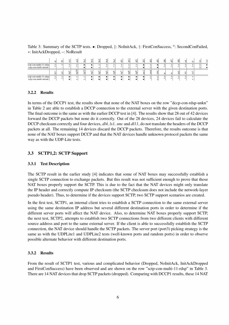
Table 3: Summary of the SCTP tests. •: Dropped, ‡: NoInitAck, †: FirstConSuccess, o: SecondConFailed,∗: InitAckDropped, –: NoResult
al ap as1
as2
be1
be2
be3
be4
bu1
dl1
dl11
dl2
dl3
dl4
dl5
dl6
dl7
dl8
ed je ls1
ls2
sctp-con-multi-11-rdsp † † † † • • ∗ † † † ‡ † • ‡ • † † † † † ‡ •sctp-con-multi-stream o – o o • • ∗ o o o ‡ o • ‡ • o o o o o ‡ •
ls3
ls5
ng1
ng10
ng11
ng2
ng3
ng4
ng6
ng7
ng8
ng9
nw1
owrt
smc
te to un1
we
zy1
sctp-con-multi-11-rdsp † † • ∗ ∗ • • • • • • • • † ‡ † † † † ∗sctp-con-multi-stream o o • ∗ ∗ • • • • • • • • o ‡ o o o o ∗
3.2.2 Results
In terms of the DCCP1 test, the results show that none of the NAT boxes on the row ”dccp-con-rdsp-unkn”in Table 2 are able to establish a DCCP connection to the external server with the given destination ports.The final outcome is the same as with the earlier DCCP test in [4]. The results show that 28 out of 42 devicesforward the DCCP packets but none do it correctly. Out of the 28 devices, 24 devices fail to calculate theDCCP checksum correctly and four devices, dl4, ls1, smc and dl11, do not translate the headers of the DCCPpackets at all. The remaining 14 devices discard the DCCP packets. Therefore, the results outcome is thatnone of the NAT boxes support DCCP and that the NAT devices handle unknown protocol packets the sameway as with the UDP-Lite tests.
3.3 SCTP1,2: SCTP Support
3.3.1 Test Description
The SCTP result in the earlier study [4] indicates that some of NAT boxes may successfully establish asingle SCTP connection to exchange packets. But this result was not sufficient enough to prove that thoseNAT boxes properly support the SCTP. This is due to the fact that the NAT devices might only translatethe IP header and correctly compute IP checksum (the SCTP checksum does not include the network-layerpseudo header). Thus, to determine if the devices support SCTP, two SCTP support scenarios are created.
In the first test, SCTP1, an internal client tries to establish a SCTP connection to the same external serverusing the same destination IP address but several different destination ports in order to determine if thedifferent server ports will affect the NAT device. Also, to determine NAT boxes properly support SCTP,the next test, SCTP2, attempts to establish two SCTP connections from two different clients with differentsource address and port to the same external server. If the client is able to successfully establish the SCTPconnection, the NAT device should handle the SCTP packets. The server port (port3) picking strategy is thesame as with the UDPLite1 and UDPLite2 tests (well-known ports and random ports) in order to observepossible alternate behavior with different destination ports.
3.3.2 Results
From the result of SCTP1 test, various and complicated behavior (Dropped, NoInitAck, InitAckDroppedand FirstConSuccess) have been observed and are shown on the row ”sctp-con-multi-11-rdsp” in Table 3.There are 14 NAT devices that drop SCTP packets (dropped). Comparing with DCCP1 results, these 14 NAT
6
devices (total 42 NATs) also have the same behavior to drop DCCP packets. In addition, 4 NAT boxes (dl4,ls1, smc and dl11) can not translate the source address and pass first SCTP INIT Chunk through the NATdevice without generating INIT-ACK Chunk back to the internal endpoints (NoInitAck). This might be dueto the source address not being correctly translated by those NAT boxes and the external server is not ableto respond with the SCTP INIT-ACK Chunk. Moreover, four NATs (zy1, be3, ng10 and ng11) can simplytranslate the IP address and pass through the first SCTP INIT Chunk, but the following SCTP INIT-ACKChunk will be dropped (InitAckDropped). Furthermore, the remaining 20 NAT devices can translate thedestination and source addresses and successfully exchange messages via them (FirstConSuccess). How-ever, as mentioned in [4], the SCTP checksum does not cover the network-layer pseudo header and the NATbox might only simply translate the IP header and this does not yet indicate that the NAT devices properlysupport SCTP.
The result of SCTP2 on the row ”sctp-con-multi-stream” in Table 3 show that 19 out of those 20 NATboxes mentioned above (the client has only one interface towards the ap, which is the only device with onlyWLAN connection. The testbed client server hardware does not currently support connections with twoWLAN interfaces and cannot perform SCTP2 test), which were able to successfully establish one SCTPconnection in the SCTP1 test, are not able to establish the second SCTP connection (SecondConFailed).This is due to the new internal endpoint’s address, which the NATs cannot translate properly. In otherwords, the NAT boxes in the testbed act as pure NAT without any SCTP support code and do not properlysupport SCTP [12].
3.4 UDP1-Sub1,2: TCP&UDP NAT mapping classification test
3.4.1 Test Description
When an internal client needs to initialise an outgoing session with an external server, the NAT device willallocate an external IP address and port pair for this session. The external server can then use this addressand port pair as the destination for packets to the internal client. Due to the loose definition of the NAT bythe IETF, many different behaviors have been observed with the NAT devices. To classify each of the NATdevices in the testbed, the following UDP1-Sub1,2 and UDP2 tests have been carried out to discover thespecific NAT Mapping and Filtering behavior of the devices. These mapping and filtering behaviors definehow the NAT devices allocate external address and port pairs each of the packet flows through the device.
To achieve this goal, the tests are based on the RFC 5780 [7] and the test software emulates the necessarySTUN properties to determine particular NAT behavior. For the TCP NAT behavior test, the tests can onlydetect the NAT Mapping behavior, whereas the UDP behavior test supports both the NAT Mapping andFiltering behavior detection.
The RFC4787 [1] specifies the NAT behavioral requirements for Unicast UDP, while the RFC5382 [3] spec-ifies the NAT behavior requirements for TCP. Both of them require that the NAT must have an ”Endpoint-Independent Mapping” behavior so that for example P2P applications are able to know and advertise theexternal address assigned to the internal peer and allow external peers to make contact with the internalpeers. In this case, UDP1 test creates series of tests to discover if the NAT device uses the Endpoint Inde-pendent Mapping (EIM), the Address-Dependent Mapping (ADM) or Address and Port Dependent Mapping(APM) behavior. In order to understand these different NAT Mapping behaviors, we suppose that the clientA with IP1 & Port1 has created a NAT binding to external server with IP2 & Port2. If another external server
7
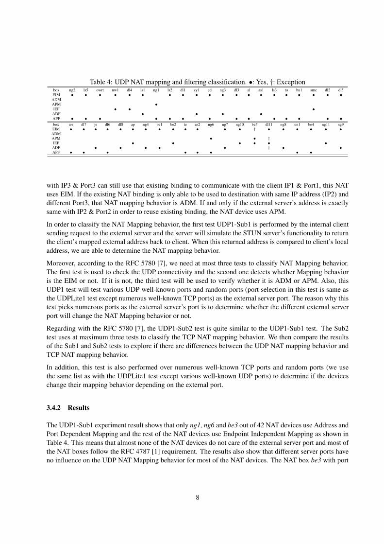
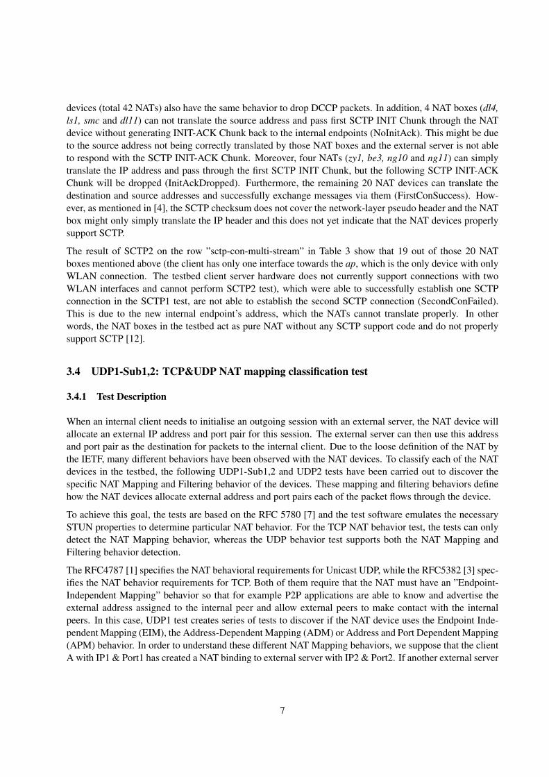
Table 4: UDP NAT mapping and filtering classification. •: Yes, †: Exceptionbox ng2 ls5 owrt nw1 dl4 ls1 ng1 ls2 dl1 zy1 ed ng3 dl3 al as1 ls3 to bu1 smc dl2 dl5EIM • • • • • • • • • • • • • • • • • • • •ADMAPM •IEF • • •
ADF • • • •APF • • • • • • • • • • • • • •box we dl7 je dl6 dl8 ap ng4 be1 be2 te as2 ng6 ng7 ng10 be3 dl11 ng8 un1 be4 ng11 ng9EIM • • • • • • • • • • • • • † • • • • • •ADMAPM • • †IEF • • • • • •
ADF • • • • • † • •APF • • • • • • • •
with IP3 & Port3 can still use that existing binding to communicate with the client IP1 & Port1, this NATuses EIM. If the existing NAT binding is only able to be used to destination with same IP address (IP2) anddifferent Port3, that NAT mapping behavior is ADM. If and only if the external server’s address is exactlysame with IP2 & Port2 in order to reuse existing binding, the NAT device uses APM.
In order to classify the NAT Mapping behavior, the first test UDP1-Sub1 is performed by the internal clientsending request to the external server and the server will simulate the STUN server’s functionality to returnthe client’s mapped external address back to client. When this returned address is compared to client’s localaddress, we are able to determine the NAT mapping behavior.
Moreover, according to the RFC 5780 [7], we need at most three tests to classify NAT Mapping behavior.The first test is used to check the UDP connectivity and the second one detects whether Mapping behavioris the EIM or not. If it is not, the third test will be used to verify whether it is ADM or APM. Also, thisUDP1 test will test various UDP well-known ports and random ports (port selection in this test is same asthe UDPLite1 test except numerous well-known TCP ports) as the external server port. The reason why thistest picks numerous ports as the external server’s port is to determine whether the different external serverport will change the NAT Mapping behavior or not.
Regarding with the RFC 5780 [7], the UDP1-Sub2 test is quite similar to the UDP1-Sub1 test. The Sub2test uses at maximum three tests to classify the TCP NAT mapping behavior. We then compare the resultsof the Sub1 and Sub2 tests to explore if there are differences between the UDP NAT mapping behavior andTCP NAT mapping behavior.
In addition, this test is also performed over numerous well-known TCP ports and random ports (we usethe same list as with the UDPLite1 test except various well-known UDP ports) to determine if the deviceschange their mapping behavior depending on the external port.
3.4.2 Results
The UDP1-Sub1 experiment result shows that only ng1, ng6 and be3 out of 42 NAT devices use Address andPort Dependent Mapping and the rest of the NAT devices use Endpoint Independent Mapping as shown inTable 4. This means that almost none of the NAT devices do not care of the external server port and most ofthe NAT boxes follow the RFC 4787 [1] requirement. The results also show that different server ports haveno influence on the UDP NAT Mapping behavior for most of the NAT devices. The NAT box be3 with port
8

Table 5: TCP NAT mapping classification. •: Yes, †: Exceptionbox ng2 ls5 owrt nw1 dl4 ls1 ng1 ls2 dl1 zy1 ed ng3 dl3 al as1 ls3 to bu1 smc dl2 dl5EIM • • • • • • • • • • • • • • • • • • •ADMAPM • •box we dl7 je dl6 dl8 ap ng4 be1 be2 te as2 ng6 ng7 ng10 be3 dl11 ng8 un1 be4 ng11 ng9EIM • • • • • • • • • • • • • • • •ADM •APM • • • † •
1701 changes its the NAT mapping behavior from APM to EIM. Moreover, the NAT device dl11 with theport 500 changes from EIM to APM. Thus, while some of the devices do change their behavior accordingto the destination port, most of the devices do not behave differently over different ports.
After the UDP1-Sub2 experiment, the result shows that 6 of the 42 NAT devices in Table 3.4.2 use the APMand 35 NAT boxes follow the RFC 5382 [3] and use the EIM. The NAT dl11 uses the ADM behavior exceptwhen the port 33434 is assigned for the external server. It will then change its NAT mapping behavior fromADM to APM. Comparing with the UDP1-Sub 1 tests results, UDP1-Sub2 demonstrates that these NATdevices (ng2, ap, ng10, be3, dl11 and ng11) have different NAT Mapping behavior between TCP and UDP.Therefore, the NAT Mapping behavior for TCP and UDP is not always same for some of devices and mostof NAT devices use the same mapping behavior. In addition, no matter what port is assigned to the externalendpoint, the TCP NAT Mapping behavior will not change apart from the device dl11. To our surprise, theNAT device dl11 has different mapping behavior in few situations.
3.5 UDP2: UDP NAT Filtering Classification
3.5.1 Test Description
Since diverse NAT filtering behavior affects the normal operation of VoIP and P2P applications, theRFC780 [7] and RFC 5382 [3] respectively recommend to use Endpoint-Independent Filtering in the trans-parent situation and Address-Dependent Filtering in the strict Filtering situation, it is necessary to take UDPNAT Filtering behavior into consideration. The UDP2 test also follows the RFC 5780 [7] and uses at mostthree tests to determine the filtering behavior of the NAT devices. The test simulates certain STUN serverfunctions to determine UDP NAT Filtering behavior. The first test is to verify the UDP connectivity, andthen, for the second test, the client sends ”change port and address” request to the external server. Thisrequest asks the server to emulate STUN server to use an alternative address to reply to the client. If theclient can receive the reply message from the different source IP address and port, the NAT device uses theeEndpoint-Independent Filtering (EIF); otherwise, a third test is needed to determine the filtering behavior.The client sends ”change port only” request to the external server. The server then sends a reply to the clientfrom an another port than the port used initially. If the client gets the reply from the server, regardless of ex-ternal server’s port, the NAT Filtering behavior is Address-Dependent Filtering (ADF); Otherwise, it is theAddress and Port-Dependent Filtering (APF). The UDP2 experiment uses the same external ports as withthe previous UDP1-Sub1 test in order to verify whether the different external servers’ port has an influenceon the UDP NAT Filtering behavior.
9
3.5.2 Results
After tests, 9 NAT devices (total 42 NATs) use EIF, 11 NAT devices use ADF, and 22 NAT devices use APFin Table 4. In addition, the common UDP NAT Filtering behavior of the NAT dl11 is EIF, but it will changeto ADF when the external server uses port 500. The results also show that setting the external ports to eitherwell-known port range or to some of the widely used ports does not affect the filtering behavior.
3.6 UDP3: UDP Throughput
3.6.1 Test Description
In order to explore how NAT boxes impact the UDP throughput performance, the throughput test seriesuse Jugi’s Traffic Generator (jtg) tool to measure the client-to-server upload UDP throughput, the server-to-client download UDP throughput and simultaneous upload and download UDP throughput. The ConstantBit Rate (CBR) of jtg is set to be 100Mb/sec (which includes IP and UDP headers) for each direction andeach throughput test is set to run for 60 seconds. The UDP3-Sub1 and UDP-3-Sub2 experiments focuson the unidirectional UDP bandwidth performance for upstream and downstream directions, respectively.The UDP3-Sub3 test measures the throughput performance when data is transferred simultaneously to bothdirections.
Figure 2: UDP upstream throughput. 0 20 40 60 80 100 ng10ls1 ng4 ng7 dl8 owrted ap dl4 te ng6 ng8 zy1 ng9 smc be4 ls5 ls3 to nw1 un1 be3 ng3 ls2 ng2 dl2 dl11as2 be1 dl7 je bu1 as1 dl6 dl3 ng1 dl1 dl5 al weThroughput [100 Mb/sec] Result (Median; 2 Iter.)Pop. Median = 61.61Pop. Mean = 53.693.6.2 Results
Based on the result of the UDP throughput in upstream direction (UDP3-Sub1) shown in Figure 2, only 12devices (out of 40 NAT devices) are able to sustain over 90Mb/sec throughput, but the rest of NAT devicesare not able to reach that high throughput. The worst throughput performance in the upstream case is theNAT device ng10 which is able to deliver traffic roughly at rate 0.01Mb/sec only and thereby experiencesextremely high packet loss rate. Furthermore, the throughput of 16 NAT devices is less than the meanthroughput of 53.69Mb/sec.
Our tests also show that devices be2 and ng11 do not cope with the 100Mb/sec CBR. The device be2stops forwarding the UDP packets for the test flow after one second and the ng11 stops forwarding the test
10
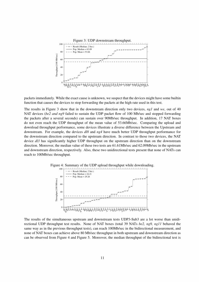
Figure 3: UDP downstream throughput. 0 20 40 60 80 100 dl3 ng10ng11ls1 ng7 owrted ap te dl4 ng6 ls5 zy1 ng8 ls3 nw1 be4 to smc ng3 un1 ng2 ls2 be3 as2 bu1 dl7 al as1 dl5 dl8 je dl1 dl6 be1 ng4 dl2 dl11ng1 weThroughput [100 Mb/sec] Result (Median; 2 Iter.)Pop. Median = 62.09Pop. Mean = 53.66packets immediately. While the exact cause is unknown, we suspect that the devices might have some builtinfunction that causes the devices to stop forwarding the packets at the high rate used in this test.
The results in Figure 3 show that in the downstream direction only two devices, ng1 and we, out of 40NAT devices (be2 and ng9 failed to sustain the UDP packet flow of 100 Mb/sec and stopped forwardingthe packets after a several seconds) can sustain over 90Mb/sec throughput. In addition, 17 NAT boxesdo not even reach the UDP throughput of the mean value of 53.66Mb/sec. Comparing the upload anddownload throughput performance, some devices illustrate a diverse difference between the Upstream anddownstream. For example, the devices dl8 and ng4 have much better UDP throughput performance forthe downstream direction compared to the upstream direction. In contrast to those two devices, the NATdevice dl3 has significantly higher UDP throughput on the upstream direction than on the downstreamdirection. Moreover, the median value of these two tests are 61.61Mb/sec and 62.09Mb/sec in the upstreamand downstream direction, respectively. Also, these two unidirectional tests present that none of NATs canreach to 100Mb/sec throughput.
Figure 4: Summary of the UDP upload throughput while downloading. 0 20 40 60 80 100 ng10dl4 ls1 ed ap ng7 ng4 owrt te dl8 un1 ng8 ng6 zy1 be3 ls5 ng3 be4 ls3 nw1 to as2 smc ng2 ls2 dl2 dl11 bu1 dl1 je as1 dl6 dl5 we ng1 be1 dl7 al dl3Throughput [100 Mb/sec] Result (Median; 2 Iter.)Pop. Median = 24.21Pop. Mean = 29.26The results of the simultaneous upstream and downstream tests UDP3-Sub3 are a lot worse than unidi-rectional UDP throughput test results. None of NAT boxes (total 39 NATs be2, ng9, ng11 behaved thesame way as in the previous throughput tests), can reach 100Mb/sec in the bidirectional measurement, andnone of NAT boxes can achieve above 80 Mb/sec throughput in both upstream and downstream direction ascan be observed from Figure 4 and Figure 5. Moreover, the median throughput of the bidirectional test is
11
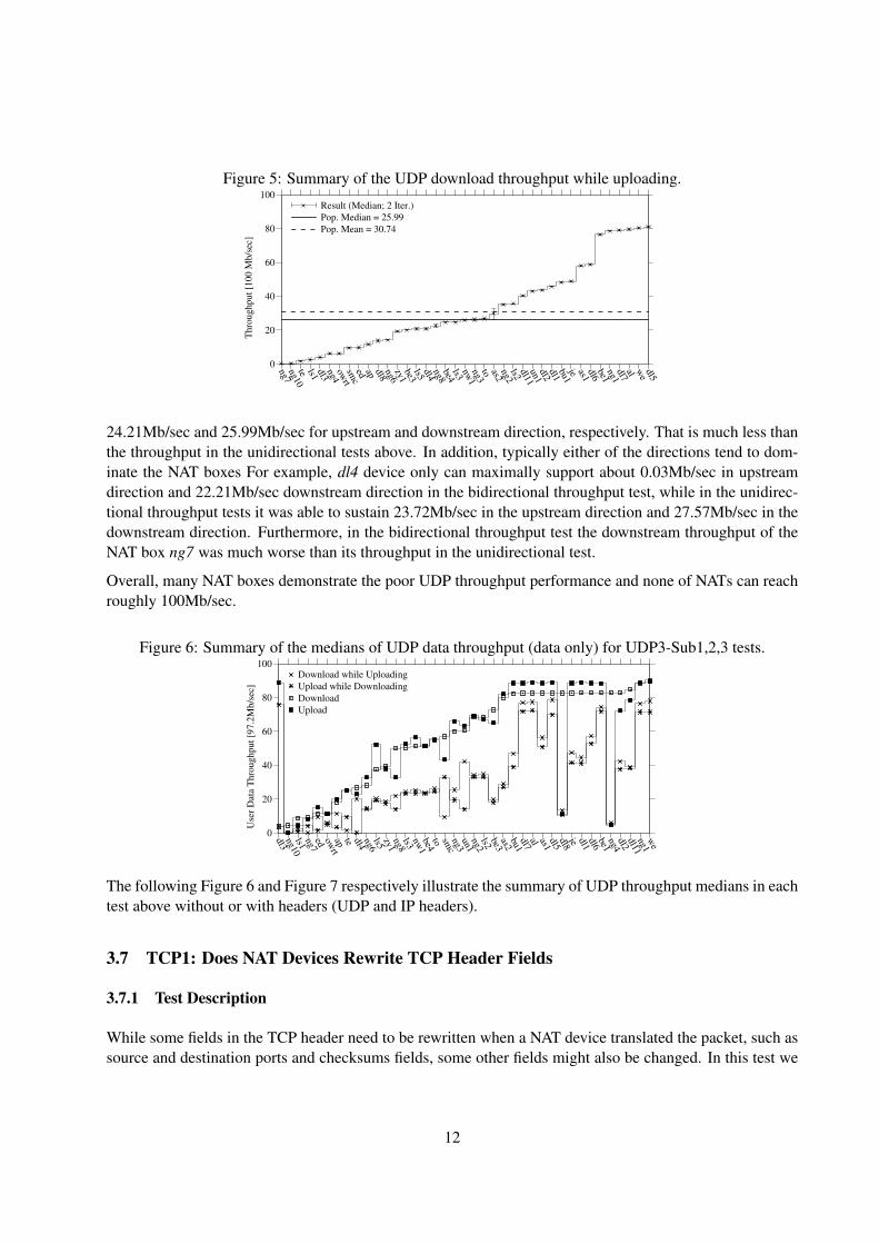
Figure 5: Summary of the UDP download throughput while uploading. 0 20 40 60 80 100 ng7 ng10te ls1 dl3 ng4 owrt smc ed ap dl8 ng6 zy1 be3 ls5 dl4 ng8 be4 ls3 nw1 ng3 to as2 ng2 ls2 dl11 un1 dl2 dl1 bu1 je as1 dl6 be1 ng1 dl7 al we dl5Throughput [100 Mb/sec] Result (Median; 2 Iter.)Pop. Median = 25.99Pop. Mean = 30.7424.21Mb/sec and 25.99Mb/sec for upstream and downstream direction, respectively. That is much less thanthe throughput in the unidirectional tests above. In addition, typically either of the directions tend to dom-inate the NAT boxes For example, dl4 device only can maximally support about 0.03Mb/sec in upstreamdirection and 22.21Mb/sec downstream direction in the bidirectional throughput test, while in the unidirec-tional throughput tests it was able to sustain 23.72Mb/sec in the upstream direction and 27.57Mb/sec in thedownstream direction. Furthermore, in the bidirectional throughput test the downstream throughput of theNAT box ng7 was much worse than its throughput in the unidirectional test.
Overall, many NAT boxes demonstrate the poor UDP throughput performance and none of NATs can reachroughly 100Mb/sec.
Figure 6: Summary of the medians of UDP data throughput (data only) for UDP3-Sub1,2,3 tests. 0 20 40 60 80 100 dl3 ng10ls1 ng7 ed owrt ap te dl4 ng6 ls5 zy1 ng8 ls3 nw1 be4 to smc ng3 un1 ng2 ls2 be3 as2 bu1 dl7 al as1 dl5 dl8 je dl1 dl6 be1 ng4 dl2 dl11 ng1 weUser Data Throughput [97.2Mb/sec] Download while UploadingUpload while DownloadingDownloadUploadThe following Figure 6 and Figure 7 respectively illustrate the summary of UDP throughput medians in eachtest above without or with headers (UDP and IP headers).
3.7 TCP1: Does NAT Devices Rewrite TCP Header Fields
3.7.1 Test Description
While some fields in the TCP header need to be rewritten when a NAT device translated the packet, such assource and destination ports and checksums fields, some other fields might also be changed. In this test we
12

Figure 7: Summary of the medians of UDP link throughput (including UDP+IP headers) for UDP3-Sub1,2,3tests. 0 20 40 60 80 100 dl3 ng10ls1 ng7 owrt ed ap te dl4 ng6 ls5 zy1 ng8 ls3 nw1 be4 to smc ng3 un1 ng2 ls2 be3 as2 bu1 dl7 al as1 dl5 dl8 je dl1 dl6 be1 ng4 dl2 dl11 ng1 weThroughput [100Mb/sec] Download while UploadingUpload while DownloadingDownloadUpload
Table 6: Summary of the TCP header test.
al ap as1
as2
be1
be2
be3
be4
bu1
dl1
dl11
dl2
dl3
dl4
dl5
dl6
dl7
dl8
ed je ls1
ls2
ls3
ls5
ng1
ng10
ng11
ng2
ng3
ng4
ng6
ng7
ng8
ng9
nw1
owrt
smc
te to un1
we
zy1
window-1024 • • • • • • • • • • • • • • • • • • • • • • • • • • • • • • • • • • • • • • • • • •window-2048 • • • • • • • • • • • • • • • • • • • • • • • • • • • • • • • • • • • • • • • • • •window-4096 • • • • • • • • • • • • • • • • • • • • • • • • • • • • • • • • • • • • • • • • • •window-65535 • • • • • • • • • • • • • • • • • • • • • • • • • • • • • • • • • • • • • • • • • •
seq • • • • • • • • • • • • • • • • • • • • • • • • • • • • • • • • • • • • • • • • • •
will check if the NAT devices change the field values of different window sizes and sequence numbers. Thesequence numbers are gathered from other tests while the window size is set 1024, 2048, 4096 and 65535.We check if the SYN packet comes through and if the field is changed.
3.7.2 Results
The tests indicate that the NAT devices are not very prone to changing TCP headers, except the fields theNAT needs to change depending on its classification, i.e. destination and source IP address and port pairsand cheksum field.
3.8 TCP2: Reserved Bits in the TCP Header
3.8.1 Test Description
The purpose of this test is to find out how the different home gateway devices treat the six reserved bits ofthe TCP header. This is important information since the different reserved bits or bit combinations might beused in the future for some purposes.
The test is performed by creating a TCP SYN packet, setting the reserved bits in the TCP header to allpossible combinations and then checking if the packets with different bit combinations go through the NATdevice, if the packet are dropped or if the fields are cleared.
13
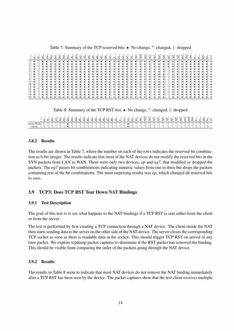
Table 7: Summary of the TCP reserved bits. •: No change, o: changed, †: dropped
al ap as1
as2
be1
be2
be3
be4
bu1
dl1
dl11
dl2
dl3
dl4
dl5
dl6
dl7
dl8
ed je ls1
ls2
ls3
ls5
ng1
ng10
ng11
ng2
ng3
ng4
ng6
ng7
ng8
ng9
nw1
owrt
smc
te to un1
we
zy1
1 • o • • • • • • • • • • • • • • • • • • • • • • • • • • • • • • • • • • • • • • • •2 • o • • • • • • • • • • • • • • • • • • • • • • • • • • • • • • • • • • • • • • • •3 • o • • • • • • • • • • • • • • • • • • • • • • • • • • • • • • • • • • • • • • • •4 • o • • • • • • • • • • • • • • • • • • • • • • • • • • • • • † • • • • • • • • • •5 • o • • • • • • • • • • • • • • • • • • • • • • • • • • • • • † • • • • • • • • • •6 • o • • • • • • • • • • • • • • • • • • • • • • • • • • • • • † • • • • • • • • • •7 • o • • • • • • • • • • • • • • • • • • • • • • • • • • • • • † • • • • • • • • • •8 • o • • • • • • • • • • • • • • • • • • • • • • • • • • • • • † • • • • • • • • • •9 • o • • • • • • • • • • • • • • • • • • • • • • • • • • • • • † • • • • • • • • • •10 • o • • • • • • • • • • • • • • • • • • • • • • • • • • • • • † • • • • • • • • • •11 • o • • • • • • • • • • • • • • • • • • • • • • • • • • • • • † • • • • • • • • • •12 • o • • • • • • • • • • • • • • • • • • • • • • • • • • • • • † • • • • • • • • • •13 • o • • • • • • • • • • • • • • • • • • • • • • • • • • • • • † • • • • • • • • • •14 • o • • • • • • • • • • • • • • • • • • • • • • • • • • • • • † • • • • • • • • • •15 • o • • • • • • • • • • • • • • • • • • • • • • • • • • • • • † • • • • • • • • • •
Table 8: Summary of the TCP RST test. •: No change, o: changed, †: dropped
al ap as1
as2
be1
be2
be3
be4
bu1
dl1
dl11
dl2
dl3
dl4
dl5
dl6
dl7
dl8
ed je ls1
ls2
ls3
ls5
ng1
ng10
ng11
ng2
ng3
ng4
ng6
ng7
ng8
ng9
nw1
owrt
smc
te to un1
we
zy1
tcp-rst-WtoL o o o o o o • o o o o o o o o o o o o o o • o o o o o o o o o o o o o o o o o o o o
tcp-rst o o o o o o • o o o o o o o o o o o o o o • o o o o o o o o o o o o o o o o o o o o
3.8.2 Results
The results are shown in Table 7, where the number on each of the rows indicates the reserved bit combina-tion as 6-bit integer. The results indicate that most of the NAT devices do not modify the reserved bits in theSYN packets from LAN to WAN. There were only two devices, ap and ng7, that modified or dropped thepackets. The ng7 passes bit combinations indicating numeric values from one to three but drops the packetscontaining rest of the bit combinations. The most surprising results was ap, which changed all reserved bitsto zero.
3.9 TCP3: Does TCP RST Tear Down NAT Bindings
3.9.1 Test Description
The goal of this test is to see what happens to the NAT bindings if a TCP RST is sent either from the clientor from the server.
The test is performed by first creating a TCP connection through a NAT device. The client inside the NATthen starts sending data to the server on the other side of the NAT device. The server closes the correspondingTCP socket as soon as there is readable data in the socket. This should trigger TCP RST on arrival of anylater packet. We explore tcpdump packet captures to determine if the RST packet has removed the binding.This should be visible from comparing the order of the packets going through the NAT device.
3.9.2 Results
The results in Table 8 seem to indicate that most NAT devices do not remove the NAT binding immediatelyafter a TCP RST has been seen by the device. The packet captures show that the test client receives multiple
14
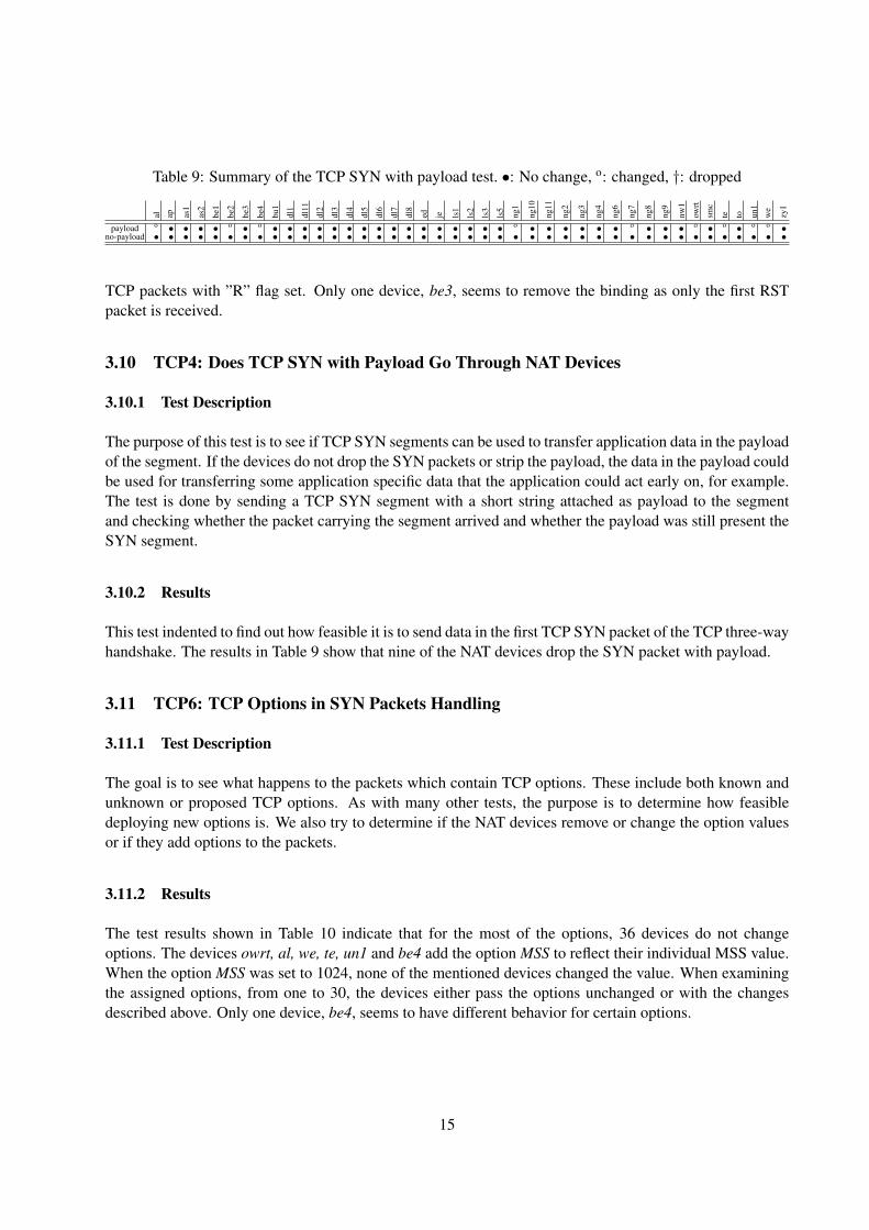
Table 9: Summary of the TCP SYN with payload test. •: No change, o: changed, †: dropped
al ap as1
as2
be1
be2
be3
be4
bu1
dl1
dl11
dl2
dl3
dl4
dl5
dl6
dl7
dl8
ed je ls1
ls2
ls3
ls5
ng1
ng10
ng11
ng2
ng3
ng4
ng6
ng7
ng8
ng9
nw1
owrt
smc
te to un1
we
zy1
payload o • • • • o • o • • • • • • • • • • • • • • • • o • • • • • • o • • • o • o • o o •no-payload • • • • • • • • • • • • • • • • • • • • • • • • • • • • • • • • • • • • • • • • • •
TCP packets with ”R” flag set. Only one device, be3, seems to remove the binding as only the first RSTpacket is received.
3.10 TCP4: Does TCP SYN with Payload Go Through NAT Devices
3.10.1 Test Description
The purpose of this test is to see if TCP SYN segments can be used to transfer application data in the payloadof the segment. If the devices do not drop the SYN packets or strip the payload, the data in the payload couldbe used for transferring some application specific data that the application could act early on, for example.The test is done by sending a TCP SYN segment with a short string attached as payload to the segmentand checking whether the packet carrying the segment arrived and whether the payload was still present theSYN segment.
3.10.2 Results
This test indented to find out how feasible it is to send data in the first TCP SYN packet of the TCP three-wayhandshake. The results in Table 9 show that nine of the NAT devices drop the SYN packet with payload.
3.11 TCP6: TCP Options in SYN Packets Handling
3.11.1 Test Description
The goal is to see what happens to the packets which contain TCP options. These include both known andunknown or proposed TCP options. As with many other tests, the purpose is to determine how feasibledeploying new options is. We also try to determine if the NAT devices remove or change the option valuesor if they add options to the packets.
3.11.2 Results
The test results shown in Table 10 indicate that for the most of the options, 36 devices do not changeoptions. The devices owrt, al, we, te, un1 and be4 add the option MSS to reflect their individual MSS value.When the option MSS was set to 1024, none of the mentioned devices changed the value. When examiningthe assigned options, from one to 30, the devices either pass the options unchanged or with the changesdescribed above. Only one device, be4, seems to have different behavior for certain options.
15
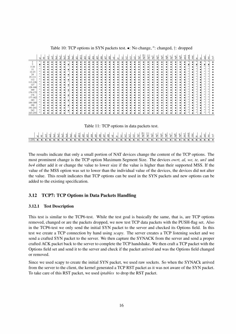
Table 10: TCP options in SYN packets test. •: No change, o: changed, †: dropped
al ap as1
as2
be1
be2
be3
be4
bu1
dl1
dl11
dl2
dl3
dl4
dl5
dl6
dl7
dl8
ed je ls1
ls2
ls3
ls5
ng1
ng10
ng11
ng2
ng3
ng4
ng6
ng7
ng8
ng9
nw1
owrt
smc
te to un1
we
zy1
1 o • • • • • • o • • • • • • • • • • • • • • • • • • • • • • • • • • • o • o • o o •2 • • • • • • • • • • • • • • • • • • • • • • • • • • • • • • • • • • • • • • • • • •
3-10 o • • • • • • o • • • • • • • • • • • • • • • • • • • • • • • • • • • o • o • o o •11 o • • • • • • • • • • • • • • • • • • • • • • • • • • • • • • • • • • o • o • o o •
12-23 o • • • • • • o • • • • • • • • • • • • • • • • • • • • • • • • • • • o • o • o o •24 o • • • • • • • • • • • • • • • • • • • • • • • • • • • • • • • • • • o • o • o o •
25-111 o • • • • • • o • • • • • • • • • • • • • • • • • • • • • • • • • • • o • o • o o •112 o • • • • • • • • • • • • • • • • • • • • • • • • • • • • • • • • • • o • o • o o •
113-126 o • • • • • • o • • • • • • • • • • • • • • • • • • • • • • • • • • • o • o • o o •127 o • • • • • • • • • • • • • • • • • • • • • • • • • • • • • • • • • • o • o • o o •
128-168 o • • • • • • o • • • • • • • • • • • • • • • • • • • • • • • • • • • o • o • o o •169 o • • • • • • • • • • • • • • • • • • • • • • • • • • • • • • • • • • o • o • o o •
170-175 o • • • • • • o • • • • • • • • • • • • • • • • • • • • • • • • • • • o • o • o o •176 o • • • • • • • • • • • • • • • • • • • • • • • • • • • • • • • • • • o • o • o o •
177-182 o • • • • • • o • • • • • • • • • • • • • • • • • • • • • • • • • • • o • o • o o •183 o • • • • • • • • • • • • • • • • • • • • • • • • • • • • • • • • • • o • o • o o •
184-189 o • • • • • • o • • • • • • • • • • • • • • • • • • • • • • • • • • • o • o • o o •190 o • • • • • • • • • • • • • • • • • • • • • • • • • • • • • • • • • • o • o • o o •
191-241 o • • • • • • o • • • • • • • • • • • • • • • • • • • • • • • • • • • o • o • o o •242 o • • • • • • • • • • • • • • • • • • • • • • • • • • • • • • • • • • o • o • o o •
243-255 o • • • • • • o • • • • • • • • • • • • • • • • • • • • • • • • • • • o • o • o o •
Table 11: TCP options in data packets test.
al ap as1
as2
be1
be2
be3
be4
bu1
dl1
dl11
dl2
dl3
dl4
dl5
dl6
dl7
dl8
ed je ls1
ls2
ls3
ls5
ng1
ng10
ng11
ng2
ng3
ng4
ng6
ng7
ng8
ng9
nw1
owrt
smc
te to un1
we
zy1
1-255 • • • • • • • • • • • • • • • • • • • • • • • • • • • • • • • • • • • • • • • • • •
The results indicate that only a small portion of NAT devices change the content of the TCP options. Themost prominent change is the TCP option Maximum Segment Size. The devices owrt, al, we, te, un1 andbe4 either add it or change the value to lower size if the value is higher than their supported MSS. If thevalue of the MSS option was set to lower than the individual value of the devices, the devices did not alterthe value. This result indicates that TCP options can be used in the SYN packets and new options can beadded to the existing specification.
3.12 TCP7: TCP Options in Data Packets Handling
3.12.1 Test Description
This test is similar to the TCP6-test. While the test goal is basically the same, that is, are TCP optionsremoved, changed or are the packets dropped, we now test TCP data packets with the PUSH-flag set. Alsoin the TCP6-test we only send the initial SYN packet to the server and checked its Options field. In thistest we create a TCP connection by hand using scapy. The server creates a TCP listening socket and wesend a crafted SYN packet to the server. We then capture the SYNACK from the server and send a propercrafted ACK packet back to the server to complete the TCP handshake. We then craft a TCP packet with theOptions field set and send it to the server and check if the packet arrived and was the Options field changedor removed.
Since we used scapy to create the initial SYN packet, we used raw sockets. So when the SYNACk arrivedfrom the server to the client, the kernel generated a TCP RST packet as it was not aware of the SYN packet.To take care of this RST packet, we used iptables to drop the RST packet.
16
3.12.2 Results
The results for TCP options in data packets shown in Table 11 look similar to results in Table 10, with onlyone exception. The NAT devices, which added TCP option MSS to the SYN packets did not add the optionto the data packets as could be expected. Also compared to the TCP6, the be4 now behaved consistently anddid not remove or drop options from the TCP header. This result indicates that TCP Options can be usedand new options can be deployed.
4 Conclusions
In this report we extended the earlier experimental study [4]. In this study, we focused on the transport layer(layer 4) behavior of home gateways. Several experiments were carried out to determine the support for newtransport protocols such as SCTP, DCCP and UDPLite. Our tests show that slightly surprisingly none of theNAT devices in our testbed support these protocols properly and prevent the deployment of these protocols.Furthermore, throughout the UDP throughput test, the quality of many of the NAT devices seriously affectthe UDP throughput performance, especially in simultaneous upstream and downstream test.
We also probed how the NAT devices behaved when encountering different TCP options and field valuesthat have either been standardized, unknown or reserved. Many of the NAT devices behaved more or lessproperly by translating the packets and preserving the field values. Only in some cases some of the deviceseither changed the values or dropped the packets. This indicates that at least in some cases new optionsand field values can be used for new options. Hence, discovering how the various NAT devices behave isessential to provide information to developers on what can be done and what to take in consideration whendeveloping new transport protocols and applications.
5 Acknowledgements
This work was supported by TEKES as part of the Future Internet programme of TIVIT (Finnish StrategicCentre for Science, Technology and Innovation in the field of ICT).
The authors would like to thank Lars Eggert and Pasi Sarolahti for their suggestions and fruitful discussionsduring the study. We would also like to thank all individuals who donated their home gateway hardwareused as a part of the testbed. In addition, we thank CSC - IT Center for Science, for donating the testbedservers to the University of Helsinki. The servers were originally a part of the CSC Sepeli cluster.
17
References
[1] F. Audet and C. Jennings. Network Address Translation (NAT) Behavioral Requirements for UnicastUDP. RFC 4787 (Best Current Practice), Jan. 2007.
[2] M. Chatel. Classical versus Transparent IP Proxies. Internet RFCs, ISSN 2070-1721, RFC 1919, Mar.1996.
[3] S. Guha, K. Biswas, B. Ford, S. Sivakumar, and P. Srisuresh. NAT Behavioral Requirements for TCP.RFC 5382 (Best Current Practice), Oct. 2008.
[4] S. Hatonen, A. Nyrhinen, L. Eggert, S. Strowes, P. Sarolahti, and M. Kojo. An Experimental Studyof Home Gateway Characteristics. In Proceedings of the 10th annual conference on Internet measure-ment, IMC ’10, pages 260–266. ACM, 2010.
[5] E. Kohler, M. Handley, and S. Floyd. Datagram Congestion Control Protocol (DCCP). RFC 4340(Proposed Standard), Mar. 2006.
[6] L.-A. Larzon, M. Degermark, S. Pink, L.-E. Jonsson, Ed., G. Fairhurst, and Ed. The Lightweight UserDatagram Protocol (UDP-Lite). Internet RFCs, ISSN 2070-1721, RFC 3828, July 2004.
[7] D. MacDonald and B. Lowekamp. NAT Behavior Discovery Using Session Traversal Utilities forNAT (STUN). Internet RFCs, ISSN 2070-1721, RFC 5780, May 2010.
[8] J. Postel. User Datagram Protocol. Internet RFCs, ISSN 2070-1721, RFC 0768, Aug. 1980.[9] J. Postel. Transmission Control Protocol. Internet RFCs, ISSN 2070-1721, RFC 0793, Sept. 1981.
[10] J. Rosenberg, R. Mahy, P. Matthews, and D. Wing. Session Traversal Utilities for NAT (STUN). RFC5389 (Proposed Standard), Oct. 2008.
[11] P. Srisuresh and M. Holdrege. IP Network Address Translator (NAT) Terminology and Considerations.Internet RFCs, ISSN 2070-1721, RFC 2663, Aug. 1999.
[12] R. Stewart and M. Tuexen. Stream Control Transmission Protocol (SCTP) Network Address Trans-lation. Internet-Draft draft-stewart-behave-sctpnat-03, Internet Engineering Task Force, Nov. 2007.Work in progress.
[13] R. Stewart, Q. Xie, K. Morneault, C. Sharp, H. Schwarzbauer, T. Taylor, I. Rytina, M. Kalla, L. Zhang,and V. Paxson. Stream Control Transmission Protocol. Internet RFCs, ISSN 2070-1721, RFC 2960,Oct. 2000.
18