Embed Size (px)
Citation preview

Study and realization of an electrostatic precipitator device
Med Ali Kouidri*, D. Mahi
Laboratory of studies and Development of Semiconductor and Dielectric Materials, LeDMaScD, University Amar Telidji of
Laghouat, Algeria
Corresponding Author Email: [email protected]
https://doi.org/10.18280/mmc_c.790415
Received: 18 February 2018
Accepted: 10 April 2018
ABSTRACT
An electrostatic filter is a device consisting of plates (receiving electrodes) arranged
vertically between which there vertically tensioned wires (electrodes) are electrically
powered by the high voltage. A negative voltage applied to the emitting electrodes,
generates the formation of electrons in the vicinity of these, which ionize the gas
molecules. These ions are attracted by the collector plates and charge the dust by corona
effect on their paths. These dusts are then attracted to the collector plates and adhere to it.
Cleaning is provided by the Hammers striking regularly these plates allow to picking up
the particles at regular intervals. The dust is thus collected to be evacuated. The obtained
results of the different geometries showed that this aspect represents a dominant influence
on the design and implementation of corona discharge reactor.
Keywords:
Electro filter, corona discharge, geometry,
electric field, ionization, particles,
environment, high voltage
1. INTRODUCTION
Most industrial units located on fertile land in sensitive
areas to pollution or appointed on ground water, are a threat
to the living and the environment. Table 1 summarizes most
of the polluting sources.
Therefore, filtering is one of remediation solutions. The
treatment can be done using various materials [1-2]:
- Cyclones; Ventured scrubbers;
- The dust collectors filter media;
- Electrostatic precipitators.
Electrostatic precipitators are often used on industrial sites
for the dust removal of flue gases and gases from flares and
chimneys before they are released into the atmosphere. They
are also used to recover valuable chemicals or metals
suspended in rejected gases that may have a market value and
be reused. These devices use electric fields to move particles
in the inter-electrode gap.
Various depollution techniques have been proposed and
several theoretical and experimental works have been carried
out to study this Phenomenon. They aim to propose
mathematical models able to simulate the behavior of the
electrostatic filter [3-4].
In this work, we propose a theoretical and practical study
defining the geometric design of a high voltage electrostatic
precipitator. It uses an emitter electrode negatively charged,
ensuring the ionization of the particles moving, under the
effect of the electric field, and are deposited on the collecting
electrode.
Table 1. Major atmospheric emission sources [27]
Installation Main pollutants expected
Gas turbine CO, CO2, NOx, Volatile Organic Compounds (COV)
Torch CO, CO2, NOx, COV
Lubrication oil events of the turbine CH4, CO, CO2, NOx, COV
Glycol boiler CO, CO2, NOx, COV
Burn pit CO, CO2, NOx, COV, carbonaceous particles
2. OPERATING PRINCIPLE OF THE REALIZED
DEVICE
The experimental setup is carried out in the laboratory for
the study and development of dielectric materials.
Its operating principle is based on electrostatic filtration,
through the negatively charged emitting electrode (see Figure
1); the electrons are emitted and activated up to the positively
charged collector electrodes.
The particles flowing in the electro filter are negatively
charged by the activated electrons where these ions deposited
and move in the direction of the collecting electrode, and
having as essential purpose the ionization depollution.
The following figure summarizes in detail of the
electrostatic filtration mechanism already cited.
Modelling, Measurement and Control C Vol. 79, No. 4, December, 2018, pp. 235-241
Journal homepage: http://iieta.org/Journals/MMC/MMC_C
235

Figure 1. Mechanism for collecting pollution
3. AIR GAP RUPTURE MECHANISM
The geometrical form of (point-plane) electrode imposes a
non-uniform field. The effective ionization coefficient �̅�
varies along the inter-electrode interval, according to the
following relationship [5-8]:
= − (1)
where:
α: The first Townsend ionization coefficient;
η: The attachment coefficient.
For high pressures and non-uniform fields, the Townsend
criterion (self-discharge) takes the form [9, 10].
0exp . 1 1
hdx
− =
(2)
where:
�̅� : The effective ionization coefficient;
γ: The second Townsend ionization coefficient;
h: The inter-electrode distance.
The integral is usually calculated along the most intense
field line. When the field reaches a critical value Ec, the
integral ∫ �̅�dx ceases to exist, and the Townsend mechanism
loses validity.
Consequently, the ionization phenomenon only appears in
the region of the inter-electrode space, which satisfies the
condition �̅� > 0 [11-13].
The number of electrons at a distance "x" as below:
( ) ( ).0.
xN x N e
=
(3)
If taking into account the non-uniform distribution then,
the number of electrons is given by:
0exp .
xc
crN dx
=
(4)
where: Ncr is the concentration of the critical charge in the
avalanche giving an ionization level for the streamer
propagation, xc is the critical distance of the avalanche Then
equation (4) becomes:
0.
xcdx k
(5)
where: xc is the length of the avalanche from the high voltage
electrode. The left side of this equation states that the
effective ionization takes place in the field region where 0 ≤𝑥 ≤ 𝑥𝑐 with the condition �̅� > 0; K is the number that takes
into account any feedback process (k = 18-20) [14-18].
The modelling of electrostatic requires the calculation of
the charge accumulated by the particles along their path. To
do this use is made of the physical models that describe the
charging process taking into account the specific conditions
present in electrostatic precipitators.
Several studies [19-22] have shown that particle loading
can be mainly attributed to two mechanisms:
- The charge per field
- The charge by diffusion.
Generally, the electric charge acquired by a particle is the
consequence of the interactions between the charge and the
ions resulting from the corona discharge. Both charging
process simultaneously involved and their relative
importance is determined primarily by the particle size and
intensity of the electric field.
The calculation of the limit charge of the particles is
mainly based on the theory developed by Pauthenier [23-24].
The temporal evolution of the charge for a particle located in
an electric field E, is described by the following expression
given by White [19]:
2
0
. .. 1 ; for
4.
sp p p s
p psp
q q qq q
dt q
= − (6)
In which ρ represents the ion density and μ is the ion
mobility. The charge limit for the field is given by the
following expression [19]:
203. . . . .
2
s rp p
r
q E d
=+
(7)
where εr is the relative permittivity of the particles. We find
in equation (7) that the limit charge per field is a function of
the intensity of the local electric field, the relative
permittivity εr of particles qp is obtained by the integration
over time of equation (6). In the particular case where the
236

distributions of the electric field and the ion space charge are
homogeneous, the integration of the relation (7) gives us:
( )
0Wit4
.h
.
.
sp p
p
p
tq t q
t
=
+
=
(8)
where τp is the characteristic charge time per field and
represents the time at which the charge of the particle reaches
half of the limit charge. In the case of electrostatic
precipitators, the intensity of the electric field and the density
of ions vary in the inter-electrode space; the value of the limit
charge will therefore be specific for each position of the
particles.
Pauthenier, Cochet [22] have proposed a simple expression
that allows the calculation of the limit charge for fine
particles of comparable size to the average free path of the
ions. This relation (9), which involves the ratio λg/dp,
represents a simple means of calculating the saturation
charge, while offering a good accuracy for particles with a
diameter greater than 0,1 μm [25].
2
210
2
2 21 . . . . .
1 2.
gs rp p
gp r
p
q d Ed
d
−
+
= + + +
(9)
where: λg is the average free path of the gas molecules can be
estimated by:
..
0.499. 8. .
gg
g
M
R T
=
(10)
where: M is the molar mass; R is the universal constant of
perfect gases (8.31 J/K.mol) and (T) absolute temperature.
Under normal conditions of temperature and pressure, the
average free path of the ions is λg = 6.53×10⁻⁸(m).
As for the diffusion charge, it concerns very fine particles,
with a diameter of less than 0.2 μm. In the charge by
diffusion, the accumulated charge quantity depends on the
particle size, the density of the ions, the average rate of
thermal agitation of the ions, the dielectric constant of the
particle, the absolute temperature of the gas and the time of
presence of the particles within the field. White [19] shows
that the evolution over time of the charge acquired by a
particle under the effect of the diffusion process is given by:
2.
10. . .
1
. .. . .
W
exp4
ith
2. .
3. .
q
p ep p
d k T
B
i
qd q dV
dt
k TV
m
=
=
(11)
where: kB = 1.38 × 10⁻²³ J / k represents the Boltzmann
constant; V1 is the thermal stirring speed of the ions and with
mi the mass of the ion. Considering a density of ions ρ
uniform, expression (11) after integration leads to:
( ) *
*0Wi
.ln 1
2. . . . . /t eh
pd
p B
tq t q
q d T k
= +
= (12)
The diffusion charge constant is given by:
08. .k .T/ d . . .d B p iv e = (13)
where: τd is the characteristic time of charge by diffusion. We
observe that equation (12) does not lead to a limit charge for
τ to infinity. However, the expression (11) shows that the
diffusion charging process is continuously influenced by the
charge dp already acquired by the particle. The corona effect
can be adequately described with the equations governing a
unipolar ion drift zone:
E grad= − = − (14)
2
0
divgrad
= =
(15)
. . .j E = = (16)
. 0j divj = = (17)
where:
E: The electric field.
Φ: The potential.
ρ: The density of the electric charge.
j: The current density.
v: The speed of ions.
μ: The movement of ions.
ε0: The permittivity of the vacuum.
The density of the electric charge ρ includes the charge by
ion diffusion and the charges accumulated by the solid
particles.
4. SIMULATION OF THE EXPERIMENTAL DEVICE
We have modeled the fields and potentials electrostatic by
the finite element method on a triangular mesh. A simulation
performed using the COMSOL multi-physics software
version 3.5b [26]. The results obtained in terms of field and
potential in the inter-electrode space taking into account the
influence of the inter-electrode distance (h), the spacing
between points (d) and the radius of curvature (r).
4.1 Geometry point-plan
In this configuration the field of study is discretise using
triangular elements linear. It is shown in Figure 2.
237

Figure 2. Mesh of the peak-plane domain
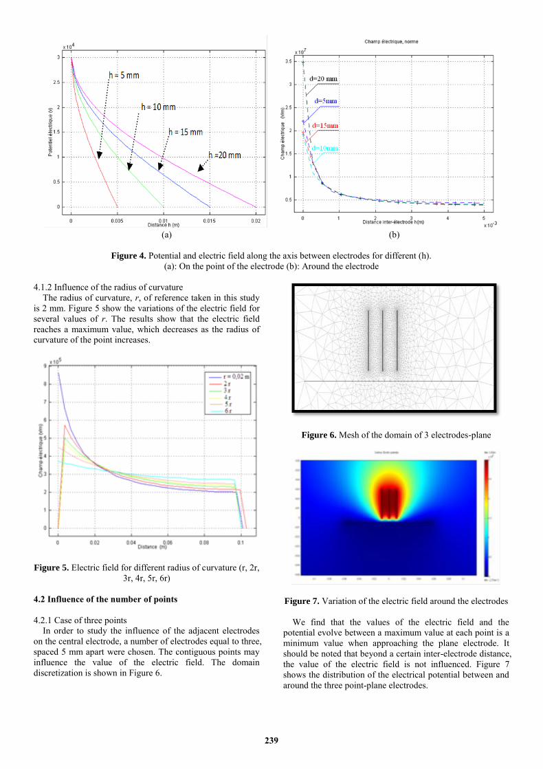
4.1.1 Influence of the inter-electrode distance (h)
The inter-electrode distance is an important factor for
control the reparation of the electric field and the potential in
the inter-electrode space. Care must be taken to avoid the
breakdown of the interval (electrical arc). We know that for
the same inter-electrode distance, the breakdown voltage is
higher than negative voltage to positive voltage. Figures 3 (a)
and 3 (b) illustrate the distribution of the electrical potential
at the head and around the high voltage electrode.
Figures 4 (a) and 4 (b) show the variations of the potential
and field distribution for several values of the inter-electrode
distance (h) 5, 10, 15 and 20mm, and an applied voltage
equal to 30kV.
(a)
(b)
Figure 3. Range of potential distributed around the point electrode.
(a): On the point of the electrode
(b): Around the electrode
238
(a) (b)
Figure 4. Potential and electric field along the axis between electrodes for different (h).
(a): On the point of the electrode (b): Around the electrode
4.1.2 Influence of the radius of curvature
The radius of curvature, r, of reference taken in this study
is 2 mm. Figure 5 show the variations of the electric field for
several values of r. The results show that the electric field
reaches a maximum value, which decreases as the radius of
curvature of the point increases.
Figure 5. Electric field for different radius of curvature (r, 2r,
3r, 4r, 5r, 6r)
4.2 Influence of the number of points
4.2.1 Case of three points
In order to study the influence of the adjacent electrodes
on the central electrode, a number of electrodes equal to three,
spaced 5 mm apart were chosen. The contiguous points may
influence the value of the electric field. The domain
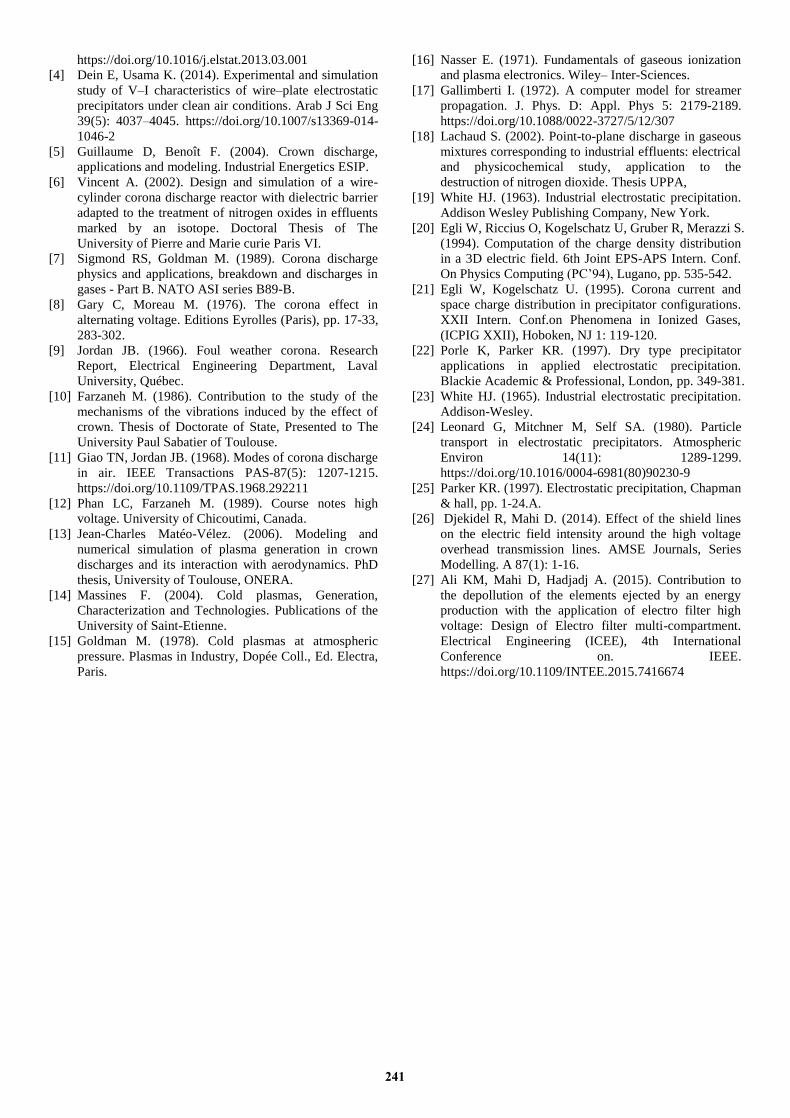
discretization is shown in Figure 6.
Figure 6. Mesh of the domain of 3 electrodes-plane
Figure 7. Variation of the electric field around the electrodes
We find that the values of the electric field and the
potential evolve between a maximum value at each point is a
minimum value when approaching the plane electrode. It
should be noted that beyond a certain inter-electrode distance,
the value of the electric field is not influenced. Figure 7
shows the distribution of the electrical potential between and
around the three point-plane electrodes.
239

4.2.2 Multi-point - Plan case
The objective of multiplying the number of electrode
points, having the same characteristics, is to obtain an intense
field and a high efficiency of the experimental device. The
simulations are performed for a number of points equal to 31,
because the experimental device makes it possible to receive
a number of electrodes equal to 31 points. The discretization
of the domain is show in Figure 8.
Figure 8. Mesh of the Multi-point structure
Figure 9 (a) shows the distribution of the electrical
potential around the multi-point-plane electrodes. We
observe certain homogeneity of the electric field and that the
field lines in the inter-electrode space are uniform. There is
no more interaction between the points.
Figure 9 (b) shows the photographs of the discharges
obtained on the experimental device. There is a uniform glow
of pre-discharges with two zones: One, bright around the
high-voltage electrode and a second, ahead of the first, of
lower intensity. We also note that the radius of the light
channel is not uniform, along the path of the latter.
(a)
(b)
Figure 9. The pace of the electric shock.
(a): Simulation result. (b): Experimental result photography
The Fig. 9 (a) illustrate the simulation of electrical field of
the multi-points Plan configuration, we noticed that the
simulate electric field in this case is intense. Thus increasing
the efficiency of electrostatics precipitation, that is what it
shows in experimental discharge Fig. 9 (b) that the plasma
between the electrodes occupies all the space, which means a
sufficient intensity of field to ionize the particles. The
obtained simulations of the electric field share some common
features with the existing experimental results about the
electric field efficiency.
5. CONCLUSION
This work focused on the study of a multi-point - plan
device. It emerges from a study that the influential
parameters that must be considered when designing the
corona reactor:
As a global conclusion of all the results obtained, we could
say that the inter-electrode distance h and the radius of
curvature of the high voltage electrode r influence the
distribution of the potential and the electric field in the inter-
electrode interval. The value of the electric field increases
exponentially when h decreases, on the other hand, the
electric field decreases as the radius of curvature of the high
voltage electrode increases.
For the case of the multi-point electrodes, we noticed that
the approach of the points acts in favour of the interferences
of the field lines leading to a net decrease of the electric field,
in particular, for the electrodes of the medium. The distance
(d) beyond a certain value equal to 5 times h, proves
necessary.
As for the corona discharge zone, we notice that from a
certain value of the applied voltage (V) to the point, and for
each value of the inter-electrode distance, an increase in the
radius of curvature leads to a significant decrease of the
electric field and that the latter is inversely proportional to
the radius of curvature.
The results obtained have shown that, the multi-point
plane configuration makes it possible to have a homogeneous
spatial distribution of the electric field with a concentration
of the field lines at the points. However, it is found that the
multiplication of the number of points, with a small radius of
curvature and an inter-electrode distance as small as it allows
having an almost homogeneous distribution of the field lines.
This improves the efficiency and performance of electro
filters.
A concordance of the results obtained between
experimentation and simulation, which explains the physical
understanding of the phenomena treated in this study.
REFERENCES
[1] Eglin T. (2012). Agricultural emissions of particles in
the air. State of play and levers of action. ADEME,
Agency for the Environment and Energy Management,
p. 34.
[2] Benamar B. (2008). The reliability of the electro
filtration of a dust charge atmosphere. PhD thesis of
Henri Poincare University. Nancy1, France.
[3] Adamiak K. (2013). Numerical models in simulating
wire-plate electrostatic precipitators. A review, Journal
of Electrostatics 71(4): 673-680.
240
https://doi.org/10.1016/j.elstat.2013.03.001
[4] Dein E, Usama K. (2014). Experimental and simulation
study of V–I characteristics of wire–plate electrostatic
precipitators under clean air conditions. Arab J Sci Eng
39(5): 4037–4045. https://doi.org/10.1007/s13369-014-
1046-2
[5] Guillaume D, Benoît F. (2004). Crown discharge,
applications and modeling. Industrial Energetics ESIP.
[6] Vincent A. (2002). Design and simulation of a wire-
cylinder corona discharge reactor with dielectric barrier
adapted to the treatment of nitrogen oxides in effluents
marked by an isotope. Doctoral Thesis of The
University of Pierre and Marie curie Paris VI.
[7] Sigmond RS, Goldman M. (1989). Corona discharge
physics and applications, breakdown and discharges in
gases - Part B. NATO ASI series B89-B.
[8] Gary C, Moreau M. (1976). The corona effect in
alternating voltage. Editions Eyrolles (Paris), pp. 17-33,
283-302.
[9] Jordan JB. (1966). Foul weather corona. Research
Report, Electrical Engineering Department, Laval
University, Québec.
[10] Farzaneh M. (1986). Contribution to the study of the
mechanisms of the vibrations induced by the effect of
crown. Thesis of Doctorate of State, Presented to The
University Paul Sabatier of Toulouse.
[11] Giao TN, Jordan JB. (1968). Modes of corona discharge
in air. IEEE Transactions PAS-87(5): 1207-1215.
https://doi.org/10.1109/TPAS.1968.292211
[12] Phan LC, Farzaneh M. (1989). Course notes high
voltage. University of Chicoutimi, Canada.
[13] Jean-Charles Matéo-Vélez. (2006). Modeling and
numerical simulation of plasma generation in crown
discharges and its interaction with aerodynamics. PhD
thesis, University of Toulouse, ONERA.
[14] Massines F. (2004). Cold plasmas, Generation,
Characterization and Technologies. Publications of the
University of Saint-Etienne.
[15] Goldman M. (1978). Cold plasmas at atmospheric
pressure. Plasmas in Industry, Dopée Coll., Ed. Electra,
Paris.
[16] Nasser E. (1971). Fundamentals of gaseous ionization
and plasma electronics. Wiley– Inter-Sciences.
[17] Gallimberti I. (1972). A computer model for streamer
propagation. J. Phys. D: Appl. Phys 5: 2179-2189.
https://doi.org/10.1088/0022-3727/5/12/307
[18] Lachaud S. (2002). Point-to-plane discharge in gaseous
mixtures corresponding to industrial effluents: electrical
and physicochemical study, application to the
destruction of nitrogen dioxide. Thesis UPPA,
[19] White HJ. (1963). Industrial electrostatic precipitation.
Addison Wesley Publishing Company, New York.
[20] Egli W, Riccius O, Kogelschatz U, Gruber R, Merazzi S.
(1994). Computation of the charge density distribution
in a 3D electric field. 6th Joint EPS-APS Intern. Conf.
On Physics Computing (PC’94), Lugano, pp. 535-542.
[21] Egli W, Kogelschatz U. (1995). Corona current and
space charge distribution in precipitator configurations.
XXII Intern. Conf.on Phenomena in Ionized Gases,
(ICPIG XXII), Hoboken, NJ 1: 119-120.
[22] Porle K, Parker KR. (1997). Dry type precipitator
applications in applied electrostatic precipitation.
Blackie Academic & Professional, London, pp. 349-381.
[23] White HJ. (1965). Industrial electrostatic precipitation.
Addison-Wesley.
[24] Leonard G, Mitchner M, Self SA. (1980). Particle
transport in electrostatic precipitators. Atmospheric
Environ 14(11): 1289-1299.
https://doi.org/10.1016/0004-6981(80)90230-9
[25] Parker KR. (1997). Electrostatic precipitation, Chapman
& hall, pp. 1-24.A.
[26] Djekidel R, Mahi D. (2014). Effect of the shield lines
on the electric field intensity around the high voltage
overhead transmission lines. AMSE Journals, Series
Modelling. A 87(1): 1-16.
[27] Ali KM, Mahi D, Hadjadj A. (2015). Contribution to
the depollution of the elements ejected by an energy
production with the application of electro filter high
voltage: Design of Electro filter multi-compartment.
Electrical Engineering (ICEE), 4th International
Conference on. IEEE.
https://doi.org/10.1109/INTEE.2015.7416674
241


