Embed Size (px)
Citation preview
Journal of Networking Technology Volume 6 Number 2 June 2015 69
ABSTRACT: In WSN, most existing mechanism around data gathering and optimal path selection result in collision.Collision further increases the possibility of packet drop. So the need is to eliminate collision during data aggregation. Thisresearch is an effort to come up with a reliable and an energy efficient Wireless Sensor Network (WSN) routing protocol. Tofind the rendezvous point for optimal transmission of data a “Splitting tree” technique is employed in tree-shaped networktopology and then to determine all the subsequent position of a sink the “ Biased Random Walk” model is used. In case of anevent, the sink gathers the data from all the source, when they are in the sensing range of rendezvous point. Otherwise relaynode is selected from its neighbor to transfer packets from the rendezvous point to sink. The proposed routing protocolsimulation results proves there is significant improvement in preventing data collision and increase in the network lifetimecompared with other routing protocol.
Keywords: Relay Node Selection, Rendezvous Point and Data Aggregation, Mobile Sink
Received: 8 January 2015, Revised 17 February 2015, Accepted 24 February 2015
© 2015 DLINE. All Rights Reserved
1. Introduction
Wireless Sensor Network is a self-organized, distributed, sensing and data propagation network formed by a large number ofsensor nodes. Nodes are resource constrained tiny autonomous devices. They are used to sense the environmental conditionsin their immediate surroundings, process the data and communicate the processed data to the base station. Sensor nodesgenerate data and transmit the gathered data to a distant base station (BS) [1].WSN can be used to monitor environment,surveillance of property and collecting data of massive fields at low cost and with less manpower. Vehicles, animals or peoplemoving around large geographic areas are attached to the sensors with robotic elements and the data is exchanged betweenindividual sensors and infrastructure nodes to drive applications like traffic, wild life monitoring, smart homes and pollutioncontrol [2].
1.1 Current challenges in WSNData collection from sensors is the key issue in WSN[3]
Study and Implementation of Routing Protocol for Data Gathering in WSN
Madhumathy, P., Sivakumar, DEaswari Engineering CollegeChennaiIndia

70 Journal of Networking Technology Volume 6 Number 2 June 2015
• Reliability and robustness of transferring data is another significant challenge [3]
• With limited battery power, sensors are expected to sense for very long time hence, energy efficient data collection arises asone of the critical issues in WSN.
• WSN have limited processing and communication capabilities.
• In real applications, the deterministic lifetime of sensor node is still an issue.
1.2 Data Gathering Using Mobile SinkA mobile sink is used for data collection from energy constrained sensor fields. It brings the sink closer to the sensors andconserves precious sensor node energy. The effectiveness of it can be determined by the total sensor energy conserved and thetime consumed in gathering the sensor data from the field or from the trajectory length implemented by the mobile sinks [4].Mobile sink in WSN optimizes the energy consumption and reduces the delay observed during data gathering. It can alsoreduce possibility of “routing hotspots” caused by fixed sinks due to the nearby heavy data flow. As the lifetime of the battery-operated sensor node is limited, mobile sink is deployed in a robot, vehicle or portable device to selectively activate only thesensor nodes interesting to the sink and deactivate the other nodes. This can considerably extend the lifetime of the sensornodes to reduce unnecessary power consumption. Mobile sink technique involves controlled movement of sink towards nodeswith higher energy for even distribution of energy in the entire network to avoid network partitioning [5-6].
1.3 Routing And Issues on Mobile Sink Data GatheringThe sink possesses significant and easily replenishable energy reserves, it should move closer to the subset of sensor devicesto collect the recorded data. The energy consumption during this process is very minimal. The sink should be within a sensorrange for single hop communication and remain within the transmitter range for successful communication. This problembecomes severe while having a high density of sensors in an area. This results in inadequacy in network communication time toupload the data of nodes to the sink and if the sink moves out of transmitter range, node has to wait till the sink returns back. Asa result, high delivery delay occurs. A network with a few mobile sinks calculates the gradients using proactive approach whichis costly in terms of energy [7]. Mobile sink brings new challenges to densely deployed and large WSN [8].
2. Literature Survey
Jae-Wan Kim et al [9] proposed IAR, an Intelligent Agent-based Routing protocol for providing efficient data delivery to mobilesink. The performance of the IAR protocol is evaluated using mathematical analysis. Results proved that the scheme effectivelysupports sink mobility with low overhead and an improvement over the triangular routing problem. However, retransmission willoccur four times, if collision occurs and this action fails.
Packet loss occurs due to the link failure between the sink and its immediate relay in this scenario.
Luo et al[10] have highlighted the difference between a mobile relay and a mobile sink. A Mobile relay collects data whenever itis closer to the sensor nodes. It transports the data to the sink through mechanical movement. As it does not use the wirelesslinks for transmission to the sink, the latency in delivering data is significant. In contrast, a mobile sink performs variousoperations like distributing the load among the sensor nodes, collecting data continuously from the sensor nodes, and movingslowly and discontinuously in the data collection process.
Bi et al [11] have considered the mobile sink as moving strategy based on residual energy of the static nodes, which is used tobalance the network workload and thereby prolong the life of the network.
Cheng et al [12] have proposed a query-based data collection in which mobile sink issues queries in the specific area whilemoving through the sensing field and the corresponding response is received through multi hop communication. The problemwith such query based systems is that the mobility of the sink causes the query and response packets to take different routes.Cheng et al (2009) analyzed the prevailing query based protocols and proposed an efficient Query-Based Data CollectionScheme which consumes lesser energy and delivered packet with minimum latency. Moreover, QBDCS chooses the optimal timeto send the query packet and tailored the routing mechanism for partial sensor nodes forwarding packets. The performance ofthe QBDCS was evaluated by comparing with a “Naïve” scheme using the simulation tool OMNeT++.
Journal of Networking Technology Volume 6 Number 2 June 2015 71
Lei & Kwon [13] propose RECPE a reliable collection protocol for aggregating data packets from the sensor nodes to the sink ina large-scale wireless sensor network. RECPE has successfully covered all the routes in the network by employing expectedtransmission count over forward links (ETF) method to construct a one-way collection tree, thereby reducing the effect ofasymmetric link in the network. Moreover, the proposed protocol also utilized Trickle algorithm and pipeline mechanism toreduce the control information and improve the efficiency of data delivery.
3. The Proposed solution
3.1 Problem FormulationIn paper [14] Mobile Sink based Reliable and Energy Efficient Data Gathering technique (MSREEDG) was proposed for datagathering in tree based network topology in WSN and compared with Biased sink mobility with adaptive stop times for lowlatency data collection (BSMASD) .The sink’s next moving position is determined by using a Biased Random Walk model. Theoptimal path for data transmission estimated by rendezvous point selection method and splitting tree process. When thesensor
Senses the data and when it is ready for transmission, the data are encoded and transmitted to the sink. The sink nodes receivethe data which is encoded from the sensors, and then it decodes the data and the resulting message is stored in local buffer. Afterdecoding all the blocks, the original data bundle is reconstructed by the mobile sink. The increase in the packet loss can beprevented by increasing the pause time of the sink.
This process can be enhanced for multiple number of sinks and designing an efficient routing protocol for data gathering . In thispaper, a relay node based routing protocol for mobile sink for data gathering for WSN is proposed.
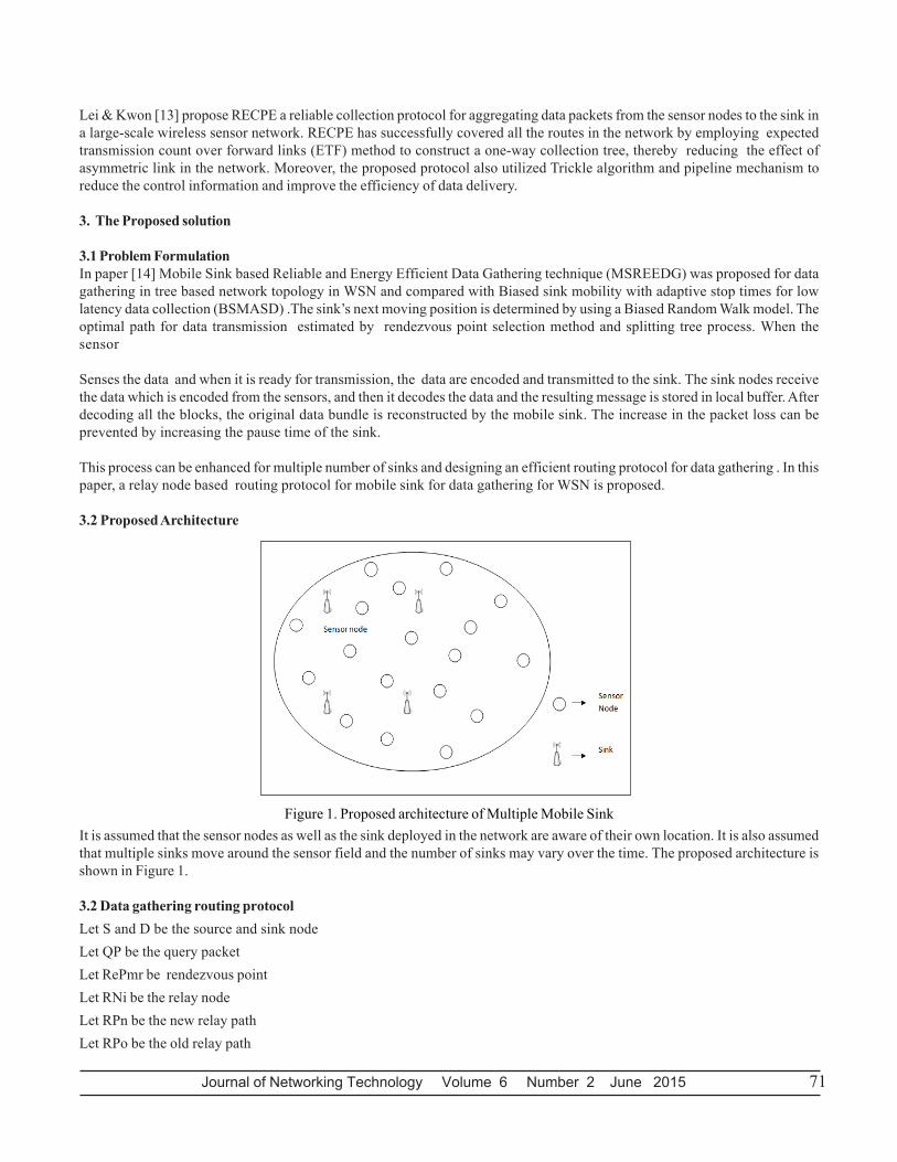
3.2 Proposed Architecture
Figure 1. Proposed architecture of Multiple Mobile SinkIt is assumed that the sensor nodes as well as the sink deployed in the network are aware of their own location. It is also assumedthat multiple sinks move around the sensor field and the number of sinks may vary over the time. The proposed architecture isshown in Figure 1.
3.2 Data gathering routing protocolLet S and D be the source and sink nodeLet QP be the query packetLet RePmr be rendezvous pointLet RNi be the relay nodeLet RPn be the new relay pathLet RPo be the old relay path

72 Journal of Networking Technology Volume 6 Number 2 June 2015
Let RP_seq be the sequence number of relay pathLet RP_mes and R_CLR are the relay path setup and clear message with RP_seq(1) If event occurs, initially, a rendezvous point (RePmr) is selected.(2) Then sink has to transmit QP to RePmr once the event occurs.The fields in the QP are shown in table-1
Table -1 Format of Query Packet
Sink ID Hop Count Transmitter Distance
(3) RePmr broadcasts the QP with hop count counter value as zero.
(4) When the neighboring nodes receives the QP, it rebroadcasts the packet by incrementing hop count counter as 1. Thus, asthe query propagates, each sensor node Ni estimates the next new hop node towards RePmr that are in one hop communicationdistance.
(5) If next new hop node > 2,
Thentwo nodes compares the packets arrival time (Tpa-)The next hop node with earlier Tpa- is chosen
End if
Source transmits the path request message (P_REQ) to its neighbors and the neighbor node that sends the (P_REP) is chosenas next new hop node.
If D is moving in the radio range of RePmr
Then
D receives the data directly from the RePmr.
Else
D chooses RNi from its neighbor nodes to transmit the data from RePmr to sink. (Relay node selection )
End if
Here, the node, which is nearest to D is selected as RN.
(6) If an event occurs, Ni enclosing it collectively processes the signal. One among the nodes becomes S to generate the datareports(7) When S matches the data sent by QP, the data is forwarded to one hop distance node.(8) If the next new hop node is failed or its battery is exhausted
Then
S ⎯⎯⎯ →⎯ REQP _ Neighi
Neighi ⎯⎯ →⎯ REPP _ S
S chooses the respective Neighi as next new hop node.
End if
Journal of Networking Technology Volume 6 Number 2 June 2015 73
3.3 Relay Node SelectionWhen D does not receive the data packets for the pre-defined time interval T, it suspects that they are out of the coverage radiorange. In order to prevent this action, the following steps are executed.
• RePmr transmits atleast one packet at interval of T/n period. ( n is integer number which consider channel loss).• If RePmr has no data to transmit in T/n duration, it transmits NULL packet . Thus, when D does not receive the data packet forT, it performs the following actions to select the relay node.
1) Relay node request message (R_REQ) is sent to its Neighi.
D ⎯⎯⎯ →⎯ REQR _ Neighi
2) Neighi node will reply to the sink.Neighi ⎯⎯⎯ →⎯ REPR _ D
3) Sink chooses the node which is nearer to it as immediate relay node.
4) The relay path message is sent through IRN.
D ⎯⎯⎯ →⎯ mesRP _ IRNi ⎯⎯⎯ →⎯ mesRP _ RePmr
Note: If D’s speed is rapid, then the distance among RePmr and IRN is more. In this case, the RNi count is increased.
5) When RePmr receives the RP_mes, data packets are transmitted in the path traversed by RP_mes. This relay path is flaggedwith RP_seq.
Note: When D moves away of radio range or after completing its relay path set up, there may be possibility of packet drop. Thisis prevented by RePmr- by caching the overheard packets which are transmitted to D. The cached packets are routed to D whenthe RePmr- receives RP_mes.
6) If D is again away from its transmission range of IRNi, then it selects new IRNi (as per step 3).
7) D then transmits RP_mes to the RePmr through the newly selected IRNi in separate relay path RPn which is flagged withRPn_SEQ.
a) When RePmr receives relay path setup message,If an RPo exists for the same sink
ThenRePmr ⎯⎯ →⎯ CLRR _ RPo
End if
If there is an old relay path for the same sink, then the RePmr transmits R_CLR message along RPo which is flagged withRPo_SEQ.
b)If a relay path receives a new RP_mes, then it does not remove the RPo state. RPo state is maintained until the path receivesR_CLR for RPo. Then a relay path is set up in the reverse path of RP_mes.
3.4 Relay Node based Routing Protocol for Multiple Mobile SinkIf an event occurs, the sink comes into contact with the RP and starts collecting the data. When the sink moves out of its
74 Journal of Networking Technology Volume 6 Number 2 June 2015
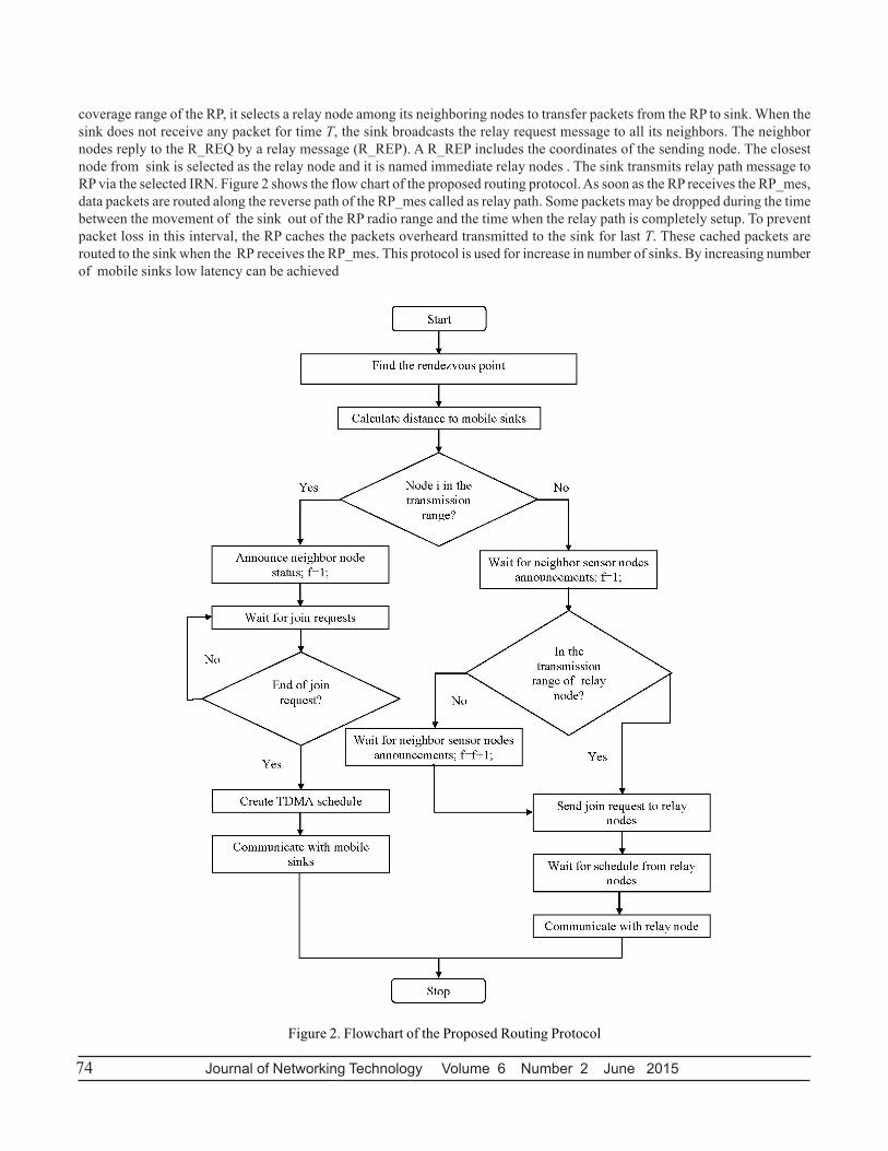
coverage range of the RP, it selects a relay node among its neighboring nodes to transfer packets from the RP to sink. When thesink does not receive any packet for time T, the sink broadcasts the relay request message to all its neighbors. The neighbornodes reply to the R_REQ by a relay message (R_REP). A R_REP includes the coordinates of the sending node. The closestnode from sink is selected as the relay node and it is named immediate relay nodes . The sink transmits relay path message toRP via the selected IRN. Figure 2 shows the flow chart of the proposed routing protocol. As soon as the RP receives the RP_mes,data packets are routed along the reverse path of the RP_mes called as relay path. Some packets may be dropped during the timebetween the movement of the sink out of the RP radio range and the time when the relay path is completely setup. To preventpacket loss in this interval, the RP caches the packets overheard transmitted to the sink for last T. These cached packets arerouted to the sink when the RP receives the RP_mes. This protocol is used for increase in number of sinks. By increasing numberof mobile sinks low latency can be achieved
Figure 2. Flowchart of the Proposed Routing Protocol
Journal of Networking Technology Volume 6 Number 2 June 2015 75
4. Simulation Parameters
NS2 simulation is employed to evaluate Relay node based Routing Protocol for Mobile Sink (RRPMS) which is proposed . In thiscase a randomly deployed sensor nodes covering the area of 600 X 600m are varied from 50,100,150,200 and 250 kbps data rate andnodes are varied from 20 to 100 nodes. The time taken for simulation is 50 sec.
4.1 The Performance Evaluation In Terms Of Number Of SinksThis section describes the simulation results of the proposed protocol when number of sinks is increased as 1, 2 and 5.All theperformance parameters were evaluated for node as well as rate.
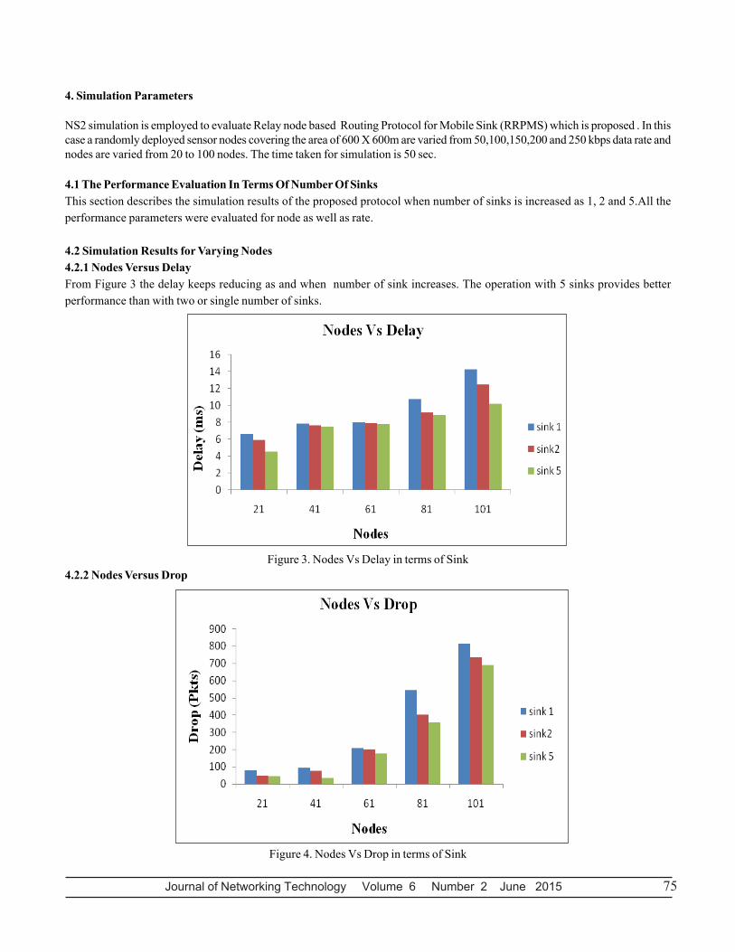
4.2 Simulation Results for Varying Nodes4.2.1 Nodes Versus DelayFrom Figure 3 the delay keeps reducing as and when number of sink increases. The operation with 5 sinks provides betterperformance than with two or single number of sinks.
Figure 3. Nodes Vs Delay in terms of Sink4.2.2 Nodes Versus Drop
Figure 4. Nodes Vs Drop in terms of Sink
76 Journal of Networking Technology Volume 6 Number 2 June 2015
Figure 4 presents the packet drop for various node scenarios when the number of sinks is varied as 1,2 and 5. It can be seen thatwhen number of nodes is increased, the drop decreases drastically for 5 sink scenario compared to 1 or 2 number of sinks.
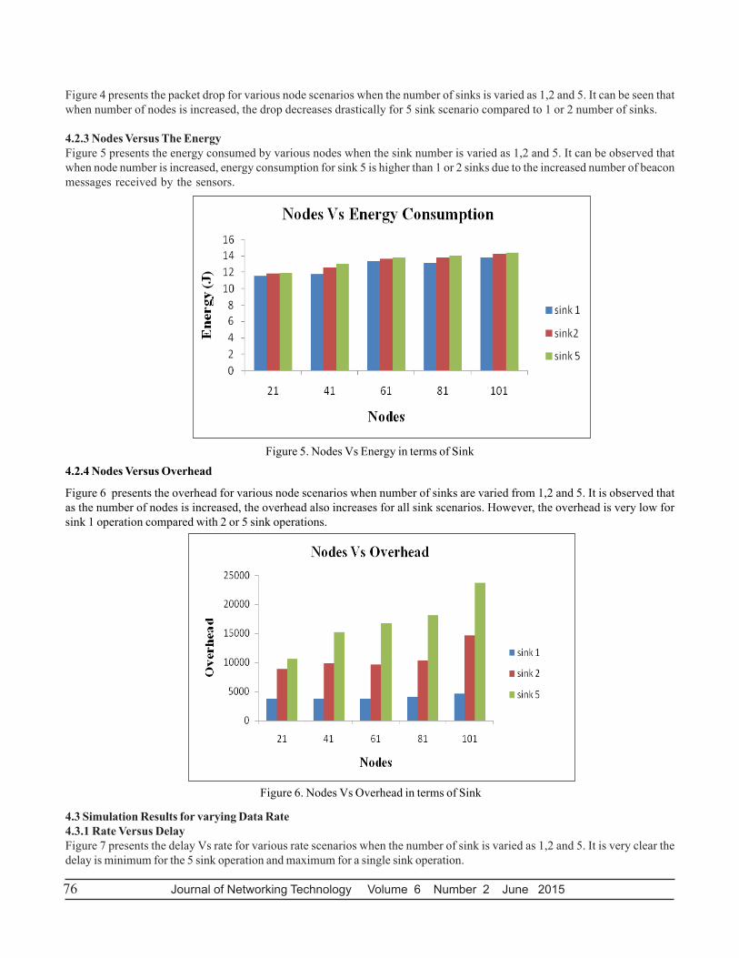
4.2.3 Nodes Versus The EnergyFigure 5 presents the energy consumed by various nodes when the sink number is varied as 1,2 and 5. It can be observed thatwhen node number is increased, energy consumption for sink 5 is higher than 1 or 2 sinks due to the increased number of beaconmessages received by the sensors.
Figure 5. Nodes Vs Energy in terms of Sink4.2.4 Nodes Versus Overhead
Figure 6 presents the overhead for various node scenarios when number of sinks are varied from 1,2 and 5. It is observed thatas the number of nodes is increased, the overhead also increases for all sink scenarios. However, the overhead is very low forsink 1 operation compared with 2 or 5 sink operations.
Figure 6. Nodes Vs Overhead in terms of Sink
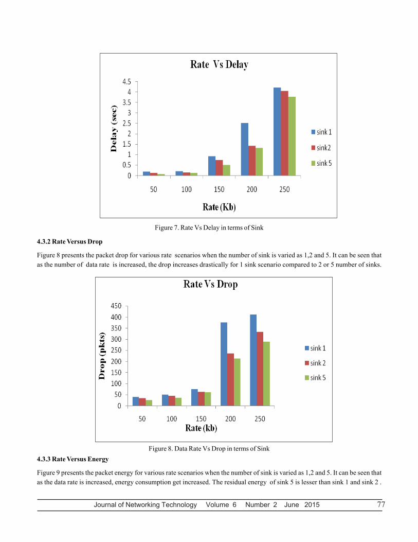
4.3 Simulation Results for varying Data Rate4.3.1 Rate Versus DelayFigure 7 presents the delay Vs rate for various rate scenarios when the number of sink is varied as 1,2 and 5. It is very clear thedelay is minimum for the 5 sink operation and maximum for a single sink operation.
Journal of Networking Technology Volume 6 Number 2 June 2015 77
Figure 7. Rate Vs Delay in terms of Sink
4.3.2 Rate Versus Drop
Figure 8 presents the packet drop for various rate scenarios when the number of sink is varied as 1,2 and 5. It can be seen thatas the number of data rate is increased, the drop increases drastically for 1 sink scenario compared to 2 or 5 number of sinks.
Figure 8. Data Rate Vs Drop in terms of Sink4.3.3 Rate Versus Energy
Figure 9 presents the packet energy for various rate scenarios when the number of sink is varied as 1,2 and 5. It can be seen thatas the data rate is increased, energy consumption get increased. The residual energy of sink 5 is lesser than sink 1 and sink 2 .

78 Journal of Networking Technology Volume 6 Number 2 June 2015
Figure 9. Rate Vs Energy in terms of Sink
4.3.4 Rate Versus Overhead
Figure 10 presents the overhead in terms of data rate for various numbers of sinks. It is observed that overhead is maximum for5 sinks scenario when compared to other sink scenarios.
Figure 10. Rate Vs Overhead in terms of Sink
Journal of Networking Technology Volume 6 Number 2 June 2015 79
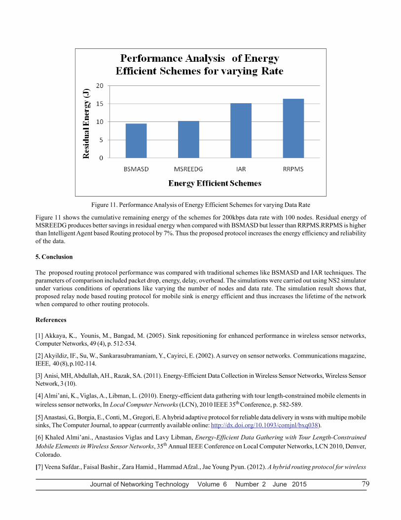
Figure 11. Performance Analysis of Energy Efficient Schemes for varying Data Rate
Figure 11 shows the cumulative remaining energy of the schemes for 200kbps data rate with 100 nodes. Residual energy ofMSREEDG produces better savings in residual energy when compared with BSMASD but lesser than RRPMS.RRPMS is higherthan Intelligent Agent based Routing protocol by 7%. Thus the proposed protocol increases the energy efficiency and reliabilityof the data.
5. Conclusion
The proposed routing protocol performance was compared with traditional schemes like BSMASD and IAR techniques. Theparameters of comparison included packet drop, energy, delay, overhead. The simulations were carried out using NS2 simulatorunder various conditions of operations like varying the number of nodes and data rate. The simulation result shows that,proposed relay node based routing protocol for mobile sink is energy efficient and thus increases the lifetime of the networkwhen compared to other routing protocols.
References
[1] Akkaya, K., Younis, M., Bangad, M. (2005). Sink repositioning for enhanced performance in wireless sensor networks,Computer Networks, 49 (4), p. 512-534.
[2] Akyildiz, IF., Su, W., Sankarasubramaniam, Y., Cayirci, E. (2002). A survey on sensor networks. Communications magazine,IEEE, 40 (8), p.102-114.
[3] Anisi, MH, Abdullah, AH., Razak, SA. (2011). Energy-Efficient Data Collection in Wireless Sensor Networks, Wireless SensorNetwork, 3 (10).
[4] Almi’ani, K., Viglas, A., Libman, L. (2010). Energy-efficient data gathering with tour length-constrained mobile elements inwireless sensor networks, In Local Computer Networks (LCN), 2010 IEEE 35th Conference, p. 582-589.
[5] Anastasi, G., Borgia, E., Conti, M., Gregori, E. A hybrid adaptive protocol for reliable data delivery in wsns with multipe mobilesinks, The Computer Journal, to appear (currrently available online: http://dx.doi.org/10.1093/comjnl/bxq038).
[6] Khaled Almi’ani., Anastasios Viglas and Lavy Libman, Energy-Efficient Data Gathering with Tour Length-ConstrainedMobile Elements in Wireless Sensor Networks, 35th Annual IEEE Conference on Local Computer Networks, LCN 2010, Denver,Colorado.
[7] Veena Safdar., Faisal Bashir., Zara Hamid., Hammad Afzal., Jae Young Pyun. (2012). A hybrid routing protocol for wireless

80 Journal of Networking Technology Volume 6 Number 2 June 2015
sensor networks with mobile sinks, Wireless and Pervasive Computing (ISWPC), 7th International Symposium on Dalian,2012
[8] Luo, J., Panchard, J., Piorkowski, M., Grossglauser, M., Hubaux, J-P 2006, MobiRoute: Routing towards a Mobile Sink forImproving Lifetime in Sensor Networks, IEEE/ACM DCOSS
[9] Bi, Y., Sun, L., Ma, J., Li, N., Khan, I., Chen, C. (2007), Hums: An autonomous moving strategy in data gathering sensornetworks, EURASIP Journal On Wireless Communication and Networking.
[10] Chen, J., Lin, R., Li., Y., Sun, Y. (2008). LQER: A Link Quality Estimation based Routing for Wireless Sensor Networks,Sensors, 8 (2), p. 1025-1038
[11] Lei, JJ., Taehyun Park., Kwon. (2013). A Reliable Data Collection Protocol Based on Erasure-resilient Code in AsymmetricWireless Sensor Networks, International Journal of Distributed Sensor Networks.
[12] Madhumathy, P., Sivakumar, D. (2014). Mobile sink based reliable and energy efficient data gathering technique for WSNJournal of Theoretical and Applied Information Technology ,10th March 61 (1).