Embed Size (px)
Citation preview

STUDY AND DESIGN OFFLIGHT DATA RECORDING SYSTEM
FOR MILITARY AIRCRAFT
Lloyd Norman Baetz

'Ul'lL'T KNOX LIBRARY
NAVAL POSTGRADUATE SCHOOL
MONTEREY. CALIF. 93940

NAVAL POSTGRADUATE SCHOOL
Monterey, California
THESISSTUDY AND DESIGN OF
FLIGHT DATA RECORDING SYSTEMSFOR MILITARY AIRCRAFT
by
Lloyd Norman Baetz
June 1976
Thesis Advisor: U. R. Kodres
Approved for public release; distribution unlimited.
T174010


SECURITY CLASSIFICATION OF THIS PACE r»i«i Data Bntarad)
REPORT DOCUMENTATION PAGE READ INSTRUCTIONSBEFORE COMPLETING FORM
1! REPORT NUMBER 2. GOVT ACCESSION NO. 3. RECIPIENT'S CATALOG NUMBER
4. TITLE (and Subtlllm)
Study and Design of Flight DataRecording Systems for MilitaryAircraft
S. TYPE OF REPORT • PERIOO COVEREDMaster s ThesisJune 1976
«. PERFORMING ORG. REPORT NUMBER
7. AUTHORfa)
Lloyd Norman Baetz
t CONTRACT OR GRANT NUMBERfaj
9. PERFORMING ORGANIZATION NAME ANO ADDRESS
Naval Postgraduate SchoolMonterey, California 93940
10. PROGRAM ELEMENT. PROJECT. TASKAREA • WORK UNIT NUMBERS
H. CONTROLLING OFFICE NAME AND ADDRESS
Naval Postgraduate SchoolMonterey, California 93940
12. REPORT DATE
June 197613. NUMBER OF PAGES
12814. MONITORING AGENCY NAME * AOORESSfl/ dlltatent horn Controlling Olllea)
Naval Postgraduate SchoolMonterey, California 93940
IS. SECURITY CLASS, (ol thla rdpert)
Unclassified
15a. DECLASSIFICATION/ DOWNGRADINGSCHEDULE
16. DISTRIBUTION STATEMENT (ot thla Report)
Approved for public release; distribution unlimited.
17. DISTRIBUTION STATEMENT 'of the amatract mnfr*d In Block 30, It different Item /taper*)
IS. SUPPLEMENTARY NOTES
IS. KEY WORDS (Continue on raweraa «><*• II neceaaary and Identity by Mode ntambet)
Flight data recordingnonvolatile solid state memorymicroprocessorsdata compressioninertial navigator
20. ABSTRACT (Continue an rarerae aid* II neeeaaawy and Identity by Mo«* member)
Investigation of aircraft wreckage does not providecrash investigators with adequate information. Crash-pro-tected flight recorder data is invaluable when determiningaccident cause factors. Inertial navigation systems pro-vide an excellent source of highly accurate flight para-meters. Nonvolatile solid state memory is available whichcan replace failure prone magnetic tape recording in flight
DD, JAT7, 1473(Page 1)
EDITION OF I NOV SS IS OBSOLETES/N 0102-014-6601 |
•ECURITY CLASSIFICATION OF THIS PAOE (When Date entered)


feCuWtTY CLASSIFICATION OF THIS P»OEW«i Ortm Entmnd-
recorder systems. Microprocessors are available with thecapability of compressing flight data for solid state memorystorage. Data compression trials indicate that a flightdata recording system using microcomputer preprocessing andnonvolatile solid state memory is feasible.
DD Form 1473, 1 Jan 73
S/N 0102-014-6601 SECURITY CLASSIFICATION OF THIS F- AGEf***" Dmtm EnCfd)


Study and Design ofFlight Data Recording Systems
for Military Aircraft
by
Lloyd Norman BaetzCaptain, Canadian Armed Forces
B.E.Sc, University of Western Ontario, 1970
Submitted in partial fulfillment of therequirements for the degree of
MASTER OF SCIENCE IN COMPUTER SCIENCE
from the
NAVAL POSTGRADUATE SCHOOLJune 1976

61*51
c.l

DUDLEY KNOX LIBRARY
NAVAL POSTGRADUATE SCHOOL
MONTEREY. CALIF. 93940
ABSTRACT
Investigation of aircraft wreckage does not provide
crash investigators with adequate information. Crash-pro-
tected flight recorder data is invaluable when determining
accident cause factors. Inertial navigation systems pro-
vide an excellent source of highly accurate flight para-
meters. Nonvolatile solid state memory is available which
can replace failure prone magnetic tape recording in flight
recorder systems. Microprocessors are available with the
capability of compressing flight data for solid state memory
storage. Data compression trials indicate that a flight
data recording system using microcomputer preprocessing and
nonvolatile solid state memory is feasible.


ACKNOWLEDGMENTS
I would like to express my sincere appreciation to all
those who provided background material and shared their ex-
perience in the flight recorder and crash investigation
fields. In particular Rodney Wingrove of NASA Ames Research
Center, Dave Althaus of Lockheed Aircraft Service Company,
Robert Foley of Hamilton Standard, and especially Carol
Roberts of the National Transportation Safety Board. I am
deeply grateful to my thesis advisors Dr. Uno Kodres and
Capt. Clyde Tuomela for their patience, guidance and timely
advice throughout this work. Finally, a very special thank
you to my wife, Myrna, for her patience and understanding.


TABLE OF CONTENTS
I. INTRODUCTION ------------------ 9
II. AIRCRAFT FLIGHT DATA RECORDERS ---------11A. HISTORY OF FLIGHT DATA RECORDING ------ 11
B. FLIGHT DATA RECORDING EQUIPMENT- ------ 14
C. DATA RECOVERY AND ANALYSIS ---------18III. FUTURE RECORDING SYSTEMS ------------23
A. INDUSTRY PROPOSALS -------------23B. A PROPOSED SYSTEM FOR MILITARY AIRCRAFT- - - 26
1. Design Restrictions- ----------262. Solid State Memory ----------- 21
3. Microcomputer Preprocessing- ------ 30
IV. DATA COMPRESSION TRIALS- ------------34V. CONCLUSIONS AND RECOMMENDATIONS- --------47APPENDIX A: SOLID STATE MEMORY TECHNOLOGY ------ 48
APPENDIX B: PROGRAM TO LIST ORIGINAL DATA ------ 59
APPENDIX C: PROGRAM TO COMPRESS DATA- --------68APPENDIX D: PROGRAM TO RECOVER AND LIST
COMPRESSED DATA -------------90APPENDIX E: PROGRAM TO PLOT ORIGINAL AND
COMPRESSED DATA ------------ -101
APPENDIX F: FLIGHT PARAMETER LISTINGS AND PLOTS - - -106
BIBLIOGRAPHY -------------------- -12 5
INITIAL DISTRIBUTION LIST- ------------- -12 8
N


LIST OF ACRONYMS
AIDS Aircraft Integrated Data Systems
ALU Arithmetic Logic Unit
ARINC Aeronautical Radio, Inc.
ATC Air Transport Control
BEAMOS Beam-Addressable Metal Oxide Semiconductor
BORAM Block-Addressable Random Access Memory
CADC Central Air Data Computer
CCD Charge-Coupled Device
CMOS Complementary Metal Oxide Semiconductor
CPU Central Processing Unit
CRT Cathode Ray Tube
DEC Digital Equipment Corporation
DFDR Digital Flight Data Recorder
EAROM Electrically-Alterable Read Only Memory
ECL Emitter-Coupled Logic
FAA Federal Aviation Administration
FAMOS Floating-Avalanche Metal Oxide Semiconductor
FDAU Flight Data Acquisition Unit
FDEP Flight Data Entry Panel
FDR Flight Data Recorder
GMT Greenwich Mean Time
2I L Integrated-In j ection Logic
INS Inertial Navigation System
LARAM Line—Addressable Random Access Memory


LSI Large Scale Integration
MNOS Metal Nitride Oxide Semiconductor
MOS Metal Oxide Semiconductor
MOSFET Metal-Oxide-Silicon Field-Effect-Transistor
NMOS N-Channel Metal Oxide Semiconductor
NTSB National Transportation Safety Board
PMOS P-Channel Metal Oxide Semiconductor
RAM Random Access Memory
ROM Read Only Memory
R/W RAM Read/Write Random Access Memory
SOS/MOS Silicon-On-Sapphire Metal Oxide Semiconductor
TTL Transistor-Transistor Logic


I . INTRODUCTION
The complexity and cost of military aircraft have contin-
ued to increase along with demands for higher performance and
safety. Unfortunately accidents continue to occur and in
some instances two, three and even more aircraft of the same
type have crashed before the cause can be determined. This
loss of high value aircraft and the possibility of crew in-
jury or death has been allowed to continue while a proven
source of accident information continues to be overlooked.
The use of recorded flight data, in accident investigation
has expanded widely in recent years and in many instances has
been the only source of evidence which could be used to estab-
lish the cause of a crash. Crash-protected flight data re-
corders have been required on large civilian aircraft since
1957 but are still not carried on most military aircraft.
This thesis is a study of the development of flight data
recording systems and their design for military aircraft.
Section II is a history of flight data recording including
a description of equipment and data recovery methods. Sec-
tion III describes future flight data recording systems and
a proposed design for use in military aircraft. Section IV
describes the data compression trials which were carried out.
The conclusions and recommendations of this report are pre-
sented in Section VI. Appendices A to F include a descrip-
tion of solid state memory technology and the programs used


in the data compression trials along with listings and
plots of original and compressed data.
10


II. AIRCRAFT FLIGHT DATA RECORDERS
A. HISTORY OF FLIGHT DATA RECORDING
Since the early days of aviation, flight data recording
has progressed from simple handwritten notes to highly so-
phisticated digital systems which record millions of measure-
ments during the period of a single flight. The recorders
principal use, until recent years, was for flight test moni-
toring and the acquisition of airworthiness data. It is now
used extensively in accident investigations. The role of
flight recording in aircraft accident investigation and pre-
vention is summarized in Refs. 1, 2 and 3.
For many years the precrash condition and performance of
an aircraft, which had been involved in an accident, was
derived from examination of the wreckage, studying mainten-
ance records, weather information, flight operation data and
human factors. Ground witnesses were the primary source of
information concerning the aircraft's flight path and maneu-
vers. The difficulties of wreckage analysis vastly increased
with the introduction of high performance aircraft. The
higher operating speeds and greater structural mass greatly
increased the release of energy and the extent of disintegra-
tion at the time of impact. In addition, higher altitude
flight and longer flight times reduced post-crash knowledge
of the operational features of the flight.
11


As a result of widely expressed demands by investigating
authorities and flight safety organizations, regulations were
established for the carriage of flight data recorders on
large civilian aircraft. These mandatory requirements gave
considerable momentum to the further development of advanced
flight data recording systems and their use in accident inves-
tigation and performance monitoring.
The following is a brief history of the development of
Federal Aviation Administration (FAA) regulations governing
flight recorder utilization and technical standards [Refs. 4
and 5] .
The first civil air regulation on flight recorders was
issued in April 1941. It required air-carrier aircraft to
record altitude and whenever the radio transmitter was turned
on or off. The compliance datfi was delayed a number of times
until finally in June 1944 the requirement was rescinded due
to maintenance difficulties and lack of replacement parts
for the recorders. A similar regulation was issued in Sep-
tember 1947 requiring aircraft of 10,000 pounds or more to
record altitude and vertical acceleration. Again this regu-
lation was rescinded in July 1948 due to lack of suitable
recording equipment.
Finally in 1957, after nine years of study, the Civil
Aeronautics Board adopted regulations requiring flight re-
corders to be installed, by September 1957, in all air-car-
rier aircraft which were over 12,000 pounds and operated at
altitudes above 25,000 feet. The parameters to be recorded
12


were airspeed, altitude, direction, vertical acceleration
and time. In September 1959, these regulations were amended
to require the retention of flight records for 60 days and
the operation of the flight recorder from the beginning of
the takeoff roll to the end of the landing roll.
The regulations were amended again, effective September
1972, to require the recording of data from which the time
of each radio transmission to air traffic control could be
determined. Effective September 1973, all large aircraft
which were certified after September 1969 and operate above
25,000 feet or are turbine powered were required to be
equipped with an expanded parameter flight recorder. The
additional parameters required were: pitch attitude, roll
attitude, sideslip angle or lateral acceleration, pitch trim
position, control column or pitch control surface position,
control wheel or lateral control surface position, rudder
pedal or yaw control surface position, thrust of each engine,
position of each thrust reverser, and trailing edge flap or
cockpit flap control position. Effective March 1974, each
recorder had to be equipped with a device to assist in locat-
ing the recorder under water.
These regulations have resulted in the installation of
crash protected flight recorders in all large civilian transport
aircraft registered in the United States. The flight data
recorder has added a new dimension to the investigation of
accidents by supplying detailed information about pre-crash
conditions. It has increased the speed and accuracy of
13


accident investigations and has made possible analysis of
the complex interactions between the flightcrew, the air-
craft and the environment.
B. FLIGHT DATA RECORDING EQUIPMENT
At present there are two types of crash protected flight
data recorders used by United States civilian air-carriers.
The older type flight data recorder (FDR) has electromech-
anically operated styli which scribe a permanent record of
the data on a metal foil recording medium. Pressure altitude,
indicated airspeed, magnetic heading and vertical accelera-
tion are recorded against a base of elapsed time. The newer
type digital flight data recorder (DFDR) records a much wider
range of aircraft flight data on magnetic tape. A flight
data acquisition unit (FDAU) is used to access analog data
from various sensors and transmitters in the aircraft and con-
vert the data to digital form for transmission to the DFDR.
A typical FDR is the Lockheed Aircraft Service Company
MOdel 109-C [Ref. 6]. It is housed in a 15 inch diameter,
insulated, stainless steel sphere and has an aluminum foil
recording medium, which can record up to 200 hours of data.
The foil is contained in a stainless steel cassette and is
fed over a teflon coated platen, which is part of the cas-
sette wall. The recording styli are mounted so that they
contact the foil surface. Altitude and airspeed are sensed
from the aircraft pitot and static pressure systems and the
recording styli are positioned mechanically in response to
14


changes in these pressures. An alternate source of altitude
and airspeed is the central air data computer (CADC) . Mag-
netic heading is obtained from the #2 aircraft compass sys-
tem and vertical acceleration is obtained from an
accelerometer located close to the aircraft's center of
gravity. Like the altitude and airspeed from the CADC, mag-
netic heading and vertical acceleration are servo signals
which position the recording styli using servo motors. The
Sundstrand Data Control Model F-542 and Fairchild Industrial
Product Model 5424 are two other versions of the FDR.
A typical DFDR is the Lockheed Aircraft Service Company
Model 209 [Ref. 7] . It records 1,670 bits of digital data
per inch, at 0.46 inches per second, on mylar magnetic re-
cording tape. There are six data tracks with over four
hours of data on each track. Tracks 1, 3 and 5 are recorded
in the forward direction and tracks 2, 4 and 6 in the reverse
direction. After all six tracks have been used, and more
than 25 hours of data have been stored, recording is resumed
on track 1, erasing the previous data. This recorder is
used with a FDAU which generates the timing signals required
to define bit, word, subframe and frame times. Each frame
of data contains four subframes, and each subframe contains
64 12-bit words representing one second of digital data. The
first word of each subframe is a synchronization word, pro-
vided by the FDAU, which signals the start of a new subframe.
The FDAU also converts the data to Harvard Bi-phase format,
and transmits it to the DFDR in serial form. The Sundstrand
15

Data Control Model 573A is another version of the DFDR.
There are 3 companies in the United States who supply
digital flight data systems using the Lockheed or Sundstrand
DFDR. They are Garrett AiResearch, Hamilton Standard and
Teledyne Controls. The recording system consists of a DFDR,
FDAU, flight data entry panel (FDEP) and the required trans-
ducers and sensors throughout the aircraft. The FDEP allows
the flightcrew to enter documentary data such as flight num-
ber and date on the recording medium. These systems are
being used primarily on the new generation of wide—bodied
aircraft, the Boeing B-747, Douglas DC-10 and Lockheed L-1011
The main concern in recorder design, aside from the
operational and recording accuracy requirements, is surviv-
ability of the recording medium in an accident. Protection
must be provided against the crushing, penetration and ac-
celeration forces of impact or explosion. The recorder
must also be able to survive exposure to fire, immersion in
sea water and the chemical attack of hydraulic, de-icing and
fire extinguishing fluids, fuels and acids. Survival of the
recording medium is primarily ensured by built-in protection,
but the recorders location in the aircraft was also found to
be an important factor. Experience during the early years
of accident investigation indicated that the rear fuselage
and tail structure are most likely to survive, or be least
severely damaged, even in a major accident. Federal Aviation
Regulations requiring recorders to be moved as far aft in
the fuselage as possible have greatly improved the recording
mediums chances of survival.
16


The flight recorders used in United States military air-
craft are installed in an ejectable airfoil package to help
ensure their survivability. The airfoil system, developed by
Leigh Instrument Limited, is being used in the USAF C-135,
C-141 and C-5A transport aircraft and is being installed in
the USN P-3C.
When crash sensors, which are located in the aircraft's
wingtips, nose and undercarriage area, detect aircraft struc-
tural breakup or deformation, they cause the airfoil package
to eject from the aircraft. The package is mounted as far
aft as possible to ensure maximum probability of survival.
If the airfoil does not eject before the aircraft strikes the
ground the rear structure will normally retain its forward
velocity long enough to ensure a good airfoil departure.
Airflow over the airfoil then allows it to generate lift and
fly away from the crash site. The aerodynamic properties of
the airfoil cause it to fly in an arc and rapidly slow to
terminal velocity and achieve a safe landing. The airfoil
contains a radio beacon which is activated when the airfoil
is separated from the aircraft. It transmits an emergency
distress signal to aid location of the crash site and the
flight recorder.
The Leigh Instrument Limited AN/ASH-20(V) flight recor-
der/locator system is being installed in the P-3C aircraft
[Ref . 8] . This system includes a magnetic tape recorder, a
beacon locator, a recorder electronics unit and a recorder
control unit. The tape recorder and beacon locator are
17


contained in the airfoil package described above. The 8-
track, bi-directional, cassette tape recorder preserves 30
minutes of flight data and audio signals. Four tracks
(three audio and one data) are utilized in each direction.
The recorder electronics unit samples 32 channels of data
from the aircraft instruments and special transducers and
processes it into 9-bit digital words. It also amplifies
audio signals from the aircraft interphone system before
they are recorded. The recorder control unit is located in
the flight deck and allows crew members to monitor system
status and voice recording quality. The beacon locator sys-
tem will transmit a 250 milliwatt, omnidirectional signal
for a minimum of 48 hours and can be detected at a range of
more than 50 miles from a height of 10,000 feet.
The system is being installed to aid accident investiga-
tion personnel in determining crash causes, to help prevent
similar crashes, to aid search aircraft in locating and
rescuing aircrew from crashed aircraft and to provide air-
craft maintenance information.
C. DATA RECOVERY AND ANALYSIS
The equipment required to recover data from the recording
medium depends upon the type of flight recorder used and
ranges from high resolution coordinate measuring equipment
to digital computers.
The data recorded on the metal foil of an FDR is recovered
using a high accuracy optical readout machine. Measurements
are made by following the scribed traces with a moving micro-
scope and logging the X and Y coordinates in inches of
18


microscope movement. These values are then plotted on a graph
with appropriate scales for analysis of aircraft operation.
Data from the DFDR is recovered using a computer based
ground processing station. Since the DFDR tape is not com-
patible with the computer, the data must first be transcribed,
in the correct format, onto a 9-track computer tape. This data,
along with information on the airline and type of aircraft
involved, may then be processed on the ground station computer
of any large computer facility. Various analysis programs
have been developed to reduce the data and display it in
readable formats. These include second-by-second listings
and plots of selected parameters versus time.
The National Transportation Safety Board (NTSB) has the
responsibility of investigating civil aircraft accidents,
reporting their probable cause and making safety recommenda-
tions to help prevent future accidents. During the 14 year
period from 1959 to 1973 NTSB reviewed 509 accidents involv-
ing FDRs and four involving DFDRs [Ref . 6] . Recorder mal-
functions or accident damage prevented readout of data in
8% of the FDR cases,but after they were relocated to the
aft of the aircraft only one recorder received damage which
prevented data readout.
NTSB has recently installed a complete data reduction
station to process data from flight data recorders [Refs. 9 and 10]
The heart of the system is a minicomputer (PDP-11/40) with
24K of core memory and a disk operating system. Peripherals
include a CRT terminal, two 9-track magnetic tape drives, a
19


high speed printer/plotter and a paper tape reader and punch.
Specialized hardware includes two DFDR readers which reformat
the Harvard bi-phase serial data into 9-track computer com-
patible format. There is also an interface to transfer the
X-Y coordinate data from the FDR readout machine into the
computer. The system software includes a program for convert-
ing raw data into the original parameter values and a search
routine for locating a specific flight record. There are
also limit exceedance, max-min, plotter and print routines.
Interaction between the operator and computer is via the
terminal in question-answer mode.
The NTSB plans to adapt an existing routine to the PDP
11/40 which will prepare a ground track of the aircraft from
the recorded data. The flight recorder data is first cor-
rected for estimated meteorological conditions, and any
available radar or other position data, to give estimates of
the geographical position of the aircraft, its heading, and
ground speed. This will be very useful in cases involving
thunderstorm activity, wake turbulence and midair collisions.
It will also aid in determining whether the flightpath of
the aircraft was consistent with its aerodynamic characteris-
tics .
In several recent accidents involving large transport
aircraft the investigators were highly dependent on data from
the DFDR since examination of the wreckage gave no clue to
the cause. In these cases DFDR data was sufficient to estab-
lish the accident cause factors. In one accident it was
possible to use the recorded data to reconstruct the aircrafts
20


motion in space by employing the airframe manufacturers 6-
degree-of -freedom computer simulation of the aircraft. The
results showed that the flight path was consistent with the
established aerodynamic characteristics of the aircraft.
This led the investigators to conclude that the aircraft
and its systems were not factors contributing to the accident
The NASA Ames Research Center has recently investigated
advanced data processing methods for combining FDR and DFDR
data with Air Transport Control (ATC) radar recordings, wind
and temperature profiles, aircraft aerodynamic data, etc.
The basic objective was to develop the capability to derive
a number of additional parameters which were not originally
recorded. The preliminary results indicate that the derived
quantities are in good agreement with the actual values
[Ref . 11] .
Ames Research Center has also used its flight simulator
facilities to derive the wind forces which were acting on
an aircraft. The DFDR, aerodynamic and engine data combined
with the equations of motion of the aircraft were fed into
the simulator. The simulators response was compared with the
actual response of the aircraft and the forces required to
make the two responses the same were attributed to wind.
The advanced methods of data processing, developed at Ames
Research Center, are applied in support of NTSB accident in-
vestigations .
The information recorded by flight recorders has become
vitally important in the understanding of the subtle causal
factors of aircraft accidents and the prevention of future
21


accidents. Wreckage no longer produces sufficient informa-
tion to assess the causal factors of accidents. Data cannot
be obtained by examining the complex hardware and avionics
circuits, such as automatic flight control systems and
navigation receivers, once power has been removed. Informa-
tion retrieved from the flight data recorder has made more
precise accident cause determination possible. It has also
provided technical substantiation for recommended solutions
to safety problems
.
22


III. FUTURE RECORDING SYSTEMS
A. INDUSTRY PROPOSALS
Advances in flight data recorder technology, particularly
those designed to Aeronautical Radio, Inc. (ARINC) standards,
have made the recording of additional data technically and
economically feasible. The increased recording capacity and
wider parameter coverage of these recorders will undoubtedly
extend their range of application.
The NTSB believes that additional information is essen-
tial to the conduct of thorough and expeditious accident in-
vestigations and has recommended the mandatory recording of
additional parameters. Investigations of recent accidents
involving wide-bodied transport aircraft have shown that
additional parameters would have provided a more complete
understanding of the underlying causal factors, and would have
produced more effective measures to prevent future accidents.
The new generation of wide-bodied aircraft, which are
being used by all major airlines, cannot be effectively main-
tained using standard maintenance procedures. In order to
cope with the extreme complexity of these aircraft, the air-
lines have started using on-board and ground processing of
flight data. Their main objectives are to reduce maintenance
costs, improve aircraft availability, increase flight safety
and increase the effectiveness of flight crews in aircraft
operations
.
23

To meet these data processing objectives, a wide range of
aircraft integrated data systems (AIDS) have been developed
for use by the airlines. They are built to meet ARINC
characteristic 573, which specifies a standard installation
for the basic flight recorder system and provides the expan-
sion capability needed for a wide variety of AIDS [Ref . 12] .
The primary role of AIDS is to record in-flight aircraft
data for subsequent processing and analysis on the ground.
Various system configurations may be employed to meet an
airline's needs based on parameters of interest and the end
use of the data. Applications range from crash-protected
recording of flight data for accident investigation to on-
board processing and recording of real-time data and further
analysis at a ground processing center. Airlines may add
just a few additional sensors or go to more complex AIDS by
adding additional signal. acquisition units, other recorders,
a computer, data compression system, etc. [Ref. 13],
The airlines and NASA Ames Research Center have been suc-
cessful in utilizing flight recorder data, voice recorder
data, radar track and meteorological data to recreate air-
craft accident conditions on flight simulators. However, in
many cases the data available requires considerable extra-
polation before it is suitable for use in the flight simula-
tor. In order for flight simulators to become a truly effec-
tive accident investigation tool, data from advanced flight
data recorders must be readily available. Conclusions and
recommendations concerning the role of the flight simulator
in aviation safety are contained in Ref. 14.
24


Most current high value aircraft are equipped with iner-
tial navigators which are another potential source of data
that could easily be adapted to flight simulators. If iner-
tial navigator parameters were recorded on every flight, they
could be used to improve the equations of motion used in
simulator mathematical models. The simulator would then more
closely represent real world characteristics and could more
easily be used to recreate accident conditions. They would
greatly increase the effectiveness of accident investigations
by providing a means of testing various hypothesis of what
occurred and should be used to validate solutions and correc-
tive actions
.
The U. S. Navy Test Pilot School has carried out a feasi-
bility study to determine if an inertial navigation system
(INS) could be utilized to derive the parameters which are
conventionally used to describe an aircrafts motion [Ref . 15]
They found that accurate earth-referenced aircraft attitude
information could be obtained directly from the INS. By
transforming the North, East and vertical velocities from
the INS into velocity components along the aircrafts three
body axes, attitude rate, accelerations, velocities, angle
of attack and sideslip were calculated. The North and East
components of wind were determined by comparing air data
computer true airspeed with INS airspeed. Results indicated
that traditional parameters were easily obtained with higher
accuracy and much less noise. Parameters normally not avail-
able could be computed and the cost of purchasing and in-
stalling sensors was eliminated.
25


Recently Hamilton Standard proposed a crash data retrie-
val system for military aircraft [Ref . 16] . They plan to
use microcomputer preprocessing along with solid state mass
data storage and large scale integrated and hybrid electronic
circuits to reduce the cost, size and weight of their system.
Lockheed Aircraft Service Company and Leigh Instruments
Limited are also looking at solid state memory and micropro-
cessors for possible use in their systems.
The importance of recorded flight data in crash investi-
gation has been demonstrated again and again. The equipment
and methods for highly complex flight recording systems are
available. Unfortunately most military aircraft still do
not carry flight recorders of any kind.
B. A PROPOSED SYSTEM FOR MILITARY AIRCRAFT
1 . Design Restrictions
Most flight data recorders have been designed for use
in large transport aircraft and so are not entirely suitable
for smaller military aircraft. Their lower inertia and more
rapid responses mean that extremes of maneuverability and
attitude will often be encountered and the sampling rates of
many parameters will have to be very high. There will also
be size and weight restrictions on small military aircraft
which were not as critical in transport aircraft. The pre-
cise position of the recorder in relation to surrounding
items of high mass is also important, particularly in the
rear-engine case. Finally the question of cost must be con-
sidered. In these days of multi-million dollar military
26


aircraft the relative cost of a crash-protected flight data
recorder system will be very small, but it goes without say-
ing that installation and maintenance costs must be kept as
low as possible.
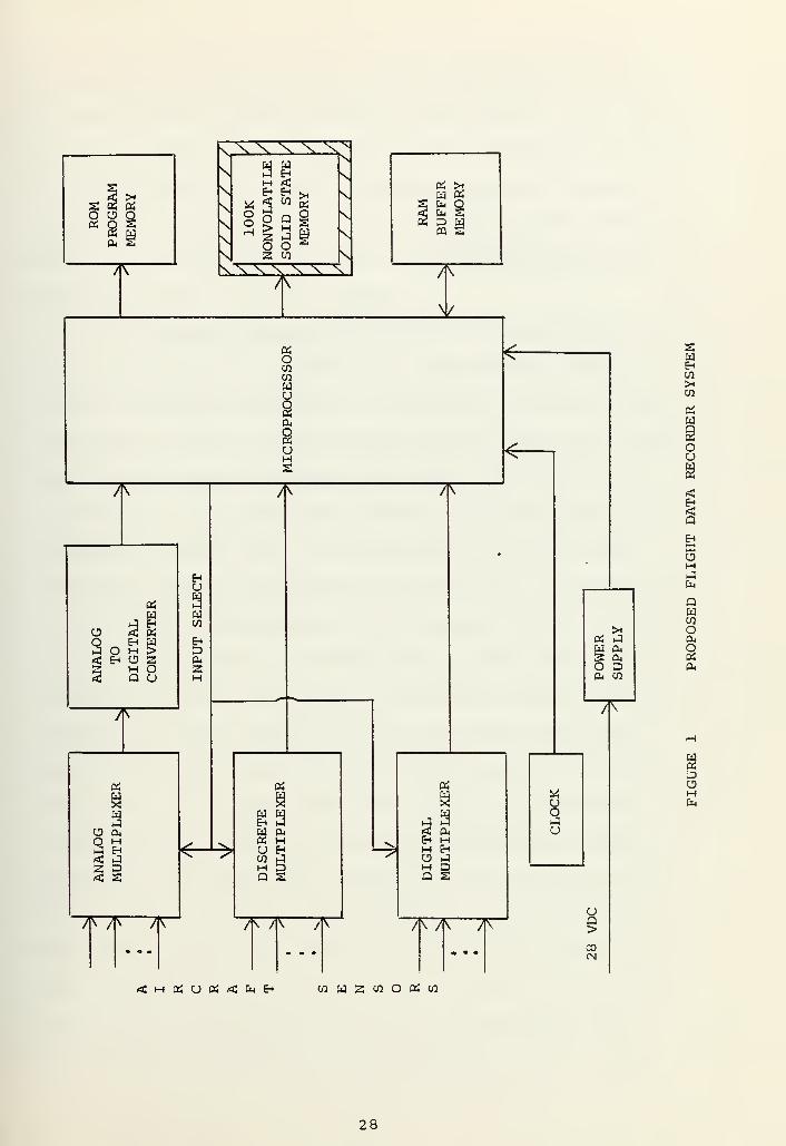
The proposed flight data recording system [Fig. 1]
incorporates recent advances in computer and solid state
memory technology to cope with the cost, size, and weight re-
strictions of military aircraft. It is also designed to cope
with their extreme operating conditions as well as provide
greater reliability and survivability of the recording medium
2 . Solid State Memory
The proposed system has a solid state recording medi-
um rather than the standard magnetic tape. The tape recorder
was eliminated since it is the most failure prone component
in flight data recording systems. This poor reliability is
due mainly to the fact that tape recorders are complex elec-
tromechanical devices with many moving parts. As a result
they require periodic maintenance such as lubrication, head
cleaning and alignment to prevent loss of data. The capa-
bility of tape recorders is also limited because of their
fixed recording and playback rates and relatively long start
and stop times. There are also the basic design problems of
wow, flutter and jitter as well as skew in multitrack sys-
tems which contribute to the bit error rate.
High density nonvolatile solid state memories, cap-
able of replacing tape recorders, are just now becoming
available. They have the advantage of high reliability due
27

8en
co
Ioug<
I
IEOHfa
QWCOo
s04
<H«UP!<fc(h CO Pl) Z CO O Pi CO
28


to no moving parts and no maintenance requirements, as well
as being easier to protect against crash damage. Solid state
memory can easily handle bursts of data which may occur prior
to a crash since its data rate is only limited by memory
cycle time. Since the rate of data storage can be easily
adjusted, only significant data need be stored and ground
processing time is greatly reduced.
The memory technologies that best lend themselves to
this role are: metai nitride oxide semiconductor (MNOS)
,
floating avalanche metal oxide semiconductor (FAMOS), mag-
netic domain bubble, charge-coupled device (CCD) and comple-
mentary metal oxide semiconductor (CMOS). Each type has
drawbacks and limitations but research and development is
continuing in most areas. A description of the various
solid state memory technologies is contained in Appendix A.
CCD and CMOS memories are basically volatile and so
require battery power to prevent loss of data [Ref . 17]
.
They have the advantage of being relatively mature techno-
logies with proven reliability and are readily available.
FAMOS and MNOS are basically nonvolatile but only MNOS is
being actively developed [Ref. 18] . Unlike conventional
random access memories, MNOS must be erased before data is
rewritten. Presently erase time is one to two seconds and
6 8the number of erase cycles is limited to from 10 to 18 .
Write time is also high (from one to two milliseconds) and
chip density is low (IK to 2K bits). The goal of current
research is a 1 microsecond write, a 1 microsecond erase
and 10 erase/write cycles before failure. Bubble memory
29


is by far the most promising technology to replace magnetic
tape [Refs. 19 and 20]. Like MNOS it is nonvolatile and
like CCD and CMOS it has very high storage density and does
not require an erase cycle. Bubble memories are not pres-
ently available, but Hatachi, Ltd. of Japan has announced
a 256K bit bubble memory, using 16K chips, which is to be
available in 1976.
3 . Microcomputer Preprocessing
Another new feature of the proposed system is micro-
computer preprocessing of data. Tape systems are limited to
a constant data rate because of the fixed recording speed
and relatively long start and stop times. This inefficient
use of memory cannot be tolerated with the relatively small
solid state memory.
The microcomputer compresses the data by eliminating
the recording of redundant data and data which changes within
an acceptable tolerance [Section IV] . Since microprocessor
instruction time is less than 10 microseconds and the number
of parameters will be less than 100, a minimum of 1000 in-
structions will be available to process each parameter dur-
ing a second. This should allow each parameter to be sampled
up to 25 times per second, since only the basic arithmetic
and logical functions are required. The only division and
multiplication operations in the compression algorithm in-
volve the number 64 so they can be carried out using right
or left shifts
.
The high sampling rate of this system will easily
handle the rapid parameter changes which may occur prior to
30


an incident or crash. Since memory size is limited, the sys-
tem must be set to provide the best balance of data rate to
data retention time.
There are a number of excellent microprocessors which
could be dedicated to this role. The lower cost of the one-
chip NMOS microprocessor and its adequate capability indicates
that it is the best choice. The bit-slice bipolar TTL micro-
processor could also be used in a 12-bit word format to match
the normal word size of the analog to digital converters.
A microprocessor results when an arithmetic logic
unit (ALU) and central processing unit (CPU) control function
are implemented on one, or a small number of large scale in-
tegrated (LSI) chips. When all five of the major computer
subsystems; CPU*control, ALU, memory, input and output are
contained in a small set of LSI packages, and a source of ex-
ternal power and timing clock are applied, the system is
called microcomputer. The microprocessor contains the basic
control logic, the circuitry for decoding instructions and
the logic circuits for processing arithmetic functions.
Both read/write random access memory (R/W RAM) and read only
memory (ROM) types are required [Appendix A] . Most micro-
processor programs are permanently encoded in ROM and data
is stored in R/W RAM. Input/output circuity is used to
interface the microcomputer with peripheral equipment.
The characteristics of interest in a microprocessor
are controlled by the performance achieved using a particular
fabrication method [Appendix A and Refs. 21-23]. The first
31


microprocessors were a byproduct of P-channel metal oxide
semiconductor (PMOS) solid state memory research and were im-
plemented on a standard 16 pin circuit package. To conserve
space and pins, both internal and external interconnections
were made using a 4-bit bidirectional multiplexed data bus.
Since both address and data could not be on the bus at the
same time, cycle time was high (10 to 20 microseconds). Like
PMOS memory, multiple power supplies were required.
The next generation of microprocessors were implemented
on a 40 pin package and used N-channel metal oxide semiconduc-
tor (NMOS) technology. They had most of the features of a
simple minicomputer including: direct memory addressing, in-
terrupt facilities, unlimited subroutine nesting, separate
8-bit address and data buses and reduced interface circuitry.
The higher speed of NMOS and elimination of address and data
multiplexing allowed reduction in cycle time from 2 to 20
microseconds
.
Bipolar transistor-transistor logic (TTL) technology
is also being used to produce microcomputer building blocks.
Because of TTLs high power dissipation, a complete processor
cannot be put in one LSI package. Instead several packages,
each containing a two of four-bit slice of the processor,
are cascaded to make a complete processor of the desired
word size. These types of processors are designed to be con-
trolled by a microprogram which may be on another chip in the
set, or in an external ROM. The microcycle time is 100-200
nanoseconds but since a number of microinstructions are required
32


to execute a program instruction, cycle time is typically
one microsecond. Bit-slice microprocessors are normally
used for designing general purpose computers or special pur-
pose high speed controllers.
2Bipolar I L technology is also being developed for
use in microprocessors. It yields circuitry that is as small
as MOS , as fast as TTL and consumes only 1/100 the power of
TTL.
Although the architecture of microprocessors may
appear primitive when compared with conventional computers,
they are amazingly powerful. Since instruction execution
times are on the order of two to nine microseconds, rela-
tively fast real-time programs can be written. Furthermore,
if a process requires higher speed, several processors can
be used in parallel to meet the speed requirements.
33


IV. DATA COMPRESSION TRIALS
Several data compression trials were carried out as a
first step in proving the design of the proposed flight re-
corder system. The DFDRs used in civilian transport air-
craft record data at a constant rate of 64 12-bit words per
second and are designed to retain the last 25 hours of
flight data. This amounts to more than 69 million bits.
At that data rate the proposed 100K solid state memory would
be able to retain data for only two minutes before it is
overwritten. This would not be sufficient data to determine
the cause of a crash in most cases, even though the flight
duration of military aircraft is much shorter than most
transport flights.
A data compression method was required which would in-
crease the retention time of significant data while still
recording sufficient new data. The basic criteria used in
compressing the data was to eliminate redundant information
so that only data which gave significant new information
about a flight would be recorded.
A 9-track computer compatible magnetic tape containing
DFDR data was obtained from the NTSB Bureau of Aviation Safety,
as a data base for the data compression trials. This tape con-
tained the complete data, from takeoff to landing, of a
10.8 hour flight which encountered approximately five minutes
of severe turbulence. It was felt that this data would give
34


a good indication of how a wide range of parameters react to
the various modes and conditions of flight. The turbulent
period would also give an indication of the density of data
which could be expected from highly maneuverable military
aircraft
.
The DFDR data tape was recorded at the Bureau's flight
data recorder laboratory, using a Digital Equipment Corpora-
tion (DEC) PDP 11/40 computer and was completely compatible
with the PDP 11/50 computer at the Naval Postgraduate School
The PDP 11/50 facility has extensive tape handling capa-
bility, a high speed printer and a number of video display
terminals for program entry and execution. The UNIX C high
level language and an excellent text editor capability are
also available.
Three "C" language programs were written during the pro-
cess of the trials. The first, ORIGIN. C was designed to
access data anywhere on the DFDR data tape, convert it to
engineering units and format it for output on the terminal
or printer. The printout was divided into four sections and
listed 37 parameters including Greenwich Mean Time (GMT).
The second program, DATA'C was designed to access data any-
where on the DFDR data tape, compress it using a simple algo-
rithm and then store the compressed data in a file called
"DFDR". The third program, RECOV'C was designed to access
the compressed data in the file "DFDR", convert it to engi-
neering units and format it for output on the terminal or
printer in the same format used by ORIGIN'C. A FORTRAN
35


program called PLOT was also written to plot the data from
ORIGIN. C and RECOV.C on the Calcomp Plotter available in the
School's main computer center. The original and recovered
data listings were written onto magnetic tape in IBM compat-
ible format and used directly as the source of data for the
plot routine.
The purpose of the programs ORIGIN. C and RECOV.C was to
provide a second by second listing of the data, both before
and after it had been compressed. The two sets of data could
be easily compared at specific points using this method, but
only by plotting both sets of data could the overall effect
of a particular data compression method be observed. The
same parameter names were used as much as possible in the
four programs to make the switch from reading one program to
the other as simple as possible [Table 1],
The initial attempt at data compression, DATA.C, involved
use of an algorithm which compared succeeding parameter values
with their most recently recorded value. If they were differ-
ent, the new value was recorded along with an identifying
label. Time was also recorded at the beginning of each
second of data so that the time, when a particular parameter
changed value, could be accurately recovered.
The labeling method used was to identify a unique number
with each parameter and record it along with the parameter.
Since there were more than 16 parameters considered, a mini-
mum of 5 bits were necessary. The data values on the DFDR
tape contain up to 12 significant bits, so a parameter and
36


GREENWICH MEAN TIME (HOURS)
GREENWICH MEAN TIME (MINUTES)
GREENWICH MEAN TIME (SECONDS)
MAGNETIC HEADING
ALTITUDE COARSE
ALTITUDE FINE
COMPUTED AIR SPEED
PITCH ATTITUDE
ROLL ATTITUDE
ENG1 THRUST (Nl)
ENG2 THRUST (Nl)
ENG3 THRUST (Nl)
LONGITUDINAL ACCELERATION
VERTICAL ACCELERATION
LATERAL ACCELERATION
TOTAL AIR TEMPERATURE
HORIZONTAL STABILIZER
ELEVATOR LEFT INBOARD
ELEVATOR RIGHT OUTBOARD
RUDDER POSITION, UPPER
RUDDER POSITION, LOWER
AILERON POSITION LEFT INBOARD
AILERON POSITION RIGHT OUTBOARD
RIGHT HAND FLAP NO. 3
GMTH
GMTM
GMTS
HEAD
ALTC
ALTF
CAS
PICH
ROLL
ENG1
ENG2
ENG3
LONG
VERG
LATG
TAT
HSTA
ELLI
ELRO
RUDU
RUDL
AILI
AIRO
FLAP
TABLE 1. List of parameters and their corresponding variablenames used throughout the programs ORIGIN. C, DATA.C,RECOV.C and PLOT.
37


its label would have required 17 bits. Since the PDP 11/50
has a 16-bit word, it was decided to divide each parameter
which had more than six significant bits into two 6-bit
parameters, coarse and fine. The letters C and F were added
to the parameter names to distinguish between the coarse and
fine parameters, respectively. To provide the additional
label numbers an extra bit was required and the discrete para-
meters were packed together, six to a label. Initially 12
bits, six of data and six of label, were recorded in 16-bit
words. Later to save even more memory space, four 12-bit
words were packed into three 16-bit words and then recorded.
Results of the initial trial in the cruise mode indicated
that, by elimination of the redundant recording of data, a
compression of 7.5 to 1 could be obtained. This meant that
at least 15 minutes of data could be retained using a 100K
bit memory. It was found that the coarse parameters were
very seldom recorded, thus providing a savings of six bits
every time a parameter was recorded. Since the discrete
parameters very seldom change , packing them together did not
take up significant extra memory. The compression obtained
using the turbulent flight data was not as good, but a reduc-
tion of 3.3 to 1 was obtained and seven minutes of data
could be retained.
Careful examination of the data listings in the cruise
flight mode indicated that many of the parameters were
fluctuating a great deal between successive minimum change
values. It was decided to modify the DATA.C program to allow
38


the parameters to change within specific tolerances without
being recorded. The parameters were allowed to fluctuate
one increment above and below their most recent recorded
value. Results indicated a compression of 11.4 to 1 in the
cruise mode and 3.9 to 1 in the turbulent phase.
Further tests were carried out on individual parameter,
using criteria such as minimum sensor accuracy and the
number of value changes during a particular time period, to
determine the best tolerance. Significant increases in the
compression factors were obtained, but only after the results
were plotted could the overall results be observed. The data
plots indicated that with greater tolerances, correspondence
between the original and compressed data was not as good.
This occurred because a parameter could be almost to its
limit in one direction or the other (from the most recently
recorded value) for an extended period of time before the
change in value would finally be recorded. It was decided to
modify DATA.C to include a running sum of the differences be-
tween the most recently recorded value and the successive new
values. When this sum reached the parameter's tolerance, the
parameter was recorded. Using this technique the tolerances
could be left higher, while still retaining good correspondence
between the original and recorded data.
Finally a statistical study was carried out to determine
the optimum tolerance for each parameter. The assumption used
was that in the cruise mode the parameter values vary within
normal acceptable limits. The tolerance for each parameter was
39


incremented until an increase did not result in a reduction of
more than one-per-minute in the number of times the parameter
was recorded. Results, using tolerances arrived at with this
method, indicated a compression of 14.2 to 1 in the cruise
mode and 4.2 to 1 in turbulence. This would allow approximate-
ly 10 minutes of data to be retained in the turbulent phase
and 30 minutes in the cruise mode.
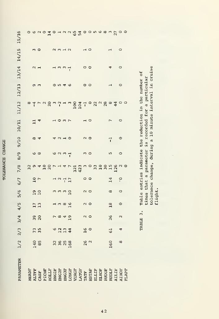
The study was carried out on a 30 minute interval of
cruise flight. The results for a 10 minute interval are con-
tained in Tables 2 and 3, and the optimum tolerances obtained
over the 30 minute interval are shown in Table 4. Figures 2
and 3 are examples of the plots of original and recovered data,
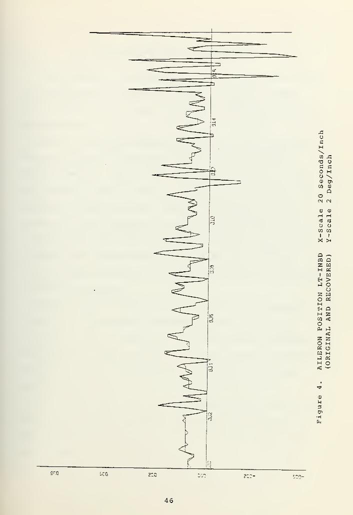
obtained using the optimum tolerances. In Figure 4 the
original and restored plots are superimposed ,and it can be
seen that they correspond very closely. The plotted data re-
presents a three minute interval of flight and includes the
first minute of turbulence. Other plots using the same inter-
val are contained in Appendix F along with listings of the
first minute of turbulent data. The final version of each of
the programs is contained in Appendices B to E
.
The results of the compression trials indicate that data
can be effectively compressed by eliminating redundancy. By
careful selection of tolerances, further compression can be
obtained while still retaining good correspondence with
original data.
40


V0 co cn o oo o mm h o cn co
in
co
CN
<T>
CO
<0
in
ocn
CNin
co
co CNin
com
CN in<*
men
com o "*^ ^r
^
CO «3<
orH
v0m
•^^ m
<*00 om
CNCOCN
ooiH
CO10
coin
rH VJ3
COST
CNm o
10
rHCNin
cnino>0
O r-\ COm
cn cnco
v0 coco
cn co co P* r^ cni0 r-i o cn in
O rH in
CNin
in
m
CO
cocNr-rHcninTrinmr-icorHrH co co
3" roco co
^ o«3* <Ti
cn o«0 O
m co o i0vfl -^ ID lO
10 O CT> covo m m oo
Cn CO CN COio in i0 <n
co o co r-» r^10 00 rH CN rH
cn
cn
CN
m O >0 10 rH COco cn co m o
rH CN
in
moo
cocn
m
o cn co co cor-- o co m cn
rH 10 r-
00 O V0rH CO 10
r^ mCNco
uCD
4-> 1
CD o
u CO
03
a £03 •H
i-i
U) 3CD T3
P CD
U4-1 c
CO
r4
1-4 CD •
CD rH P-Q X!
|4JH
a !-t r-(
CO 4-1
CD rH-C 3 CD
4-> O 10
•H •HCD 4->
4-> M H03 03 Ou Cm•H CT3 m -HC-H u r-i
03
CD
4HB
vH TI CD
r4 CD 4J4J T3 Cc i-4 •Ho
o CD
CD CD 4J
rH u aja ao3 CO •H&H •H s
co cn corH coCN r-i
r^r^
inCN co
CN CN 00cn 10CN r-\
CO 10 P* CNCO P CO > •"tf
00cn
ID
CN COco in-^ CN
in CN CN or-i r-i <-4 *$•
rH r-i rH CO
r» co10
COmCO
cn
WE-«
§Cm
b fa CuiifcjAtiifcih EmPmQhhXJHOimtJOUfcirtlH<E-tC0UJOCJO2CtJEHEHEHH3^ CJ Cm C* W W 3
iu <j-, D-i Eu
O D J MPm JID H
Eh K W W « a! <& Q
En &MQ Cm
41

vo OvQCNO"3, 0'H(NcNm«;i, oOLr>vOcomr~-oor-i rH V0 If) CN
\If)
in m o CN C") rH CN H O rH O
rH
rH\mr-i
nrH\CN
\o
\CO
CN
o\ en
<-\ n en rHl
O if) * vD
o o
o o
•sr o
r-i O
CN CO^r^CNOmCNrHfOO'*!—IOCNCNC0C0"^*OOr-i I CN I O O I CN CN ^
•-i ^ rH o ro r~»
O CO ** ^< CN rH O\
U3 CO vO CN ro rHI
rH O
CN O
en o
rH O
If) O
co CNCD'^oor^rH'tfr^rHmroOmOOLnvocNO\m rHCN cncn n H fO rl Nm «3*
OrH
r- r-i CN rH r-»
1 rH
v0\if)
rHo en CO en o
rH
if) rH 00 CO UD
"3enoCN
r~ CO "3* C7i
rH
nCN
en If)
en^) CN
rHen rj.
o o
CN O
CN O
CN O
vO O
<* o
CO o
co o
VD CNCN
CU
CO4H •H
3u M
u <fl UCU rHA 3 a£ o •rl
3 •Hc •P rH
r< fl
CU CO >JZ Q* r)
p CU
03 -Pc c•H •r<
G MH CU
4->
H XJ 3P CU CO T3 •H3 iH aT30) o!H cu
urH
<D (U-C CO4J H
scu M •H4-> CU Mn5 -p 3u cu T3•H sT3 id *.
C r( CU
•H (0 3»O) S
CO <d<D rcj X!H orl PP rcj CU
c £0) P G •
flj -Pcu U) H £rH CU cu en-Q e rH -H03 •H HH -P +J >4H
V0•^
en
WaCQ
EH
CN O if) CN v£) if) COt co en en cn vDVO CNCN
O CO10
fa faQ
fa fafafafafafafafa fafafafafafafafafafaaCJrHCNr0OUUfai<MO3pJrHQa|wj<HOSssow<<cnr^JD3HH.-3
42


TOLERANCE IN MINIMUM
PARAMETER TOLERANCE ENGINEERING UNITS SENSOR ACCURACY
HEADF 8 0.70 deg 2 deg
ALTFF 5 5 feet 80 feet at 50,000
CASF 4 1 knot 4 knots at 450
PICHF 4 0.35 deg 2 deg
ROLLF 8 0.70 deg 2 deg
ENG1F 2 0.06% 2%
ENG2F 2 0.06% 2%
ENG3F 2 0.06% 2%
LONGF 4 0.002 g 0.05 g
VERGF 12 0.0275 g 0.2 g
LATGF 12 0.006 g 0.05 g
TATF 2 1°C 1°C
HSTAF 1 0.088 deg 1 deg
ELLIF 12 0.425 deg 2 deg
ELROF 4 0.15 deg 2 deg
RUDUF 12 0.39 deg 2 deg
RUDLF 4 0.13 deg 2 deg
AILIF 16 0.499 deg 2 deg
AIROF 1 0.04 deg 2 deg
FLAPF 4 0.35 deg 3 deg
TABLE 4. Table entries indicate the optimum tolerance obtained overa 30 minute interval, the corresponding tolerance in engineer-ing units and the minimum sensor tolerance for each parameter.
43


AOGH\to AT3 UG gO Ho \co enw <u
QoCM CM
<U 0)
OW CO
1 I
X! >*
2HoHOS
o
QCQ
SHI
EH
SOHEh
HCO
ocu
soW
H
CM
cu
Oi•H
SCO tec z;c zee-
44


X!OaH\T3 Oc ao Ho \0) CnCfl 0)
QOCN CN
0) (1)
CJ
CO CO
1 I
Q
>oCJ
w
QPQ
HI
SoHEh
Hen
Ocu
soa;
w
H
a)
u3
45

-CoaH\en £T3 oc cH
O \0) Di
w <D
Qo(N MCU <1)
r-i rH
m (0
OCO CO
x: :*
QPQ
SQWen
fa
>Oow«
Q
<
<
HoH
H O
Eh
3OHEh
HCO
Oa>
2OOS
w
Hfa
i~0-
46


V. CONCLUSIONS AND RECOMMENDATIONS
Investigation of aircraft wreckage does not provide enough
investigators with adequate information. Crash-protected
flight recorder data is invaluable when determining accident
cause factors .
Inertial navigation systems, which are in most military
aircraft, provide an excellent source of highly accurate
flight parameters. Nonvolatile solid state memory is avail-
able and may be used to replace failure prone magnetic tape
recording in flight recorder systems. Microprocessors are
available with the capability of preprocessing flight data
to conserve space for solid state memory storage. Data com-
pression trials indicate that in cruise flight 30 minutes
and in turbulent conditions 10 minutes of data can be retained
in solid state memory.
These conclusions indicate that a flight data recording
system using microcomputer preprocessing and nonvolatile
solid state memory is feasible. It is therefore recommended
that a prototype system be built and tested as soon as possible
and that the inertial navigator be considered as a primary
source of data.
It is hoped that this report will help develop the interest
and concern required to develop this system for military air-
craft and provide a starting point for further research and
thesis work.
47


APPENDIX A
SOLID STATE MEMORY TECHNOLOGY
A. COMPUTER MEMORY TECHNOLOGY
The rapid growth of electronic data processing over the
last 20 years was made possible by the development of com-
puters using larger and faster memories. Attempts are con-
tinuing to improve the speed and reduce the cost of computer
memories but memory is still one of the limiting factors in
computer system development.
In the past, magnetic-f erri te core, disk, drum and tape
were the dominant storage mediums, but the situation has
rapidly changed since the introduction in 1970 of metal-oxide-
semiconductor (MOS) memory. The first semiconductor memory
applications were in cache memories and microprogram storage,
which required its fast access speed. Recent developments
have made them practical for main memory and may extend their
application to secondary storage. Other areas of memory de-
velopment that offer great promise are change-coupled devices,
magnetic bubble and electron-beam-addressable memories.
The following is a short description of the various memory
technologies, most applicable to future computer systems, along
with the factors which influence their usefulness in flight
data recording systems. MOS and bipolar are the two major semi-
conductor memory technologies and generally MOS provides low-
cost memories while bipolar provides high-performance [Refs.
24 and 25]
.
48


1 . MPS Memory Types
MOS memories are based on the metal-oxide-silicon
field-effect transistor (MOSFET) . Information is stored in
MOS memories by depositing a charge on a parasitic or dif-
fused capacitor and trapping it there by turning off the
MOSFET. The term dynamic results from the fact that, despite
the high impedence and low leakage of the MOSFET, the capa-
citor's charge eventually will leak off and so must be regu-
larly refreshed to preserve the contents of memory. They
are relatively slow since the low transconductance of the
MOSFET reduces the amount of drive current available to charge
the parasitic capacitances in the memory address and data
lines. It is possible to produce static as well as dynamic
MOS memories, but dynamic memories provide better speed and
power characteristics than static and also allow higher chip
packing density. MOS memories are volatile meaning that stored
data is lost when power is removed.
a. PMOS
P-channel MOS (PMOS) is the most mature semicon-
ductor memory technology. It got its name from the fact that
the conducting channel between the source and drain of the
MOSFET was p-type material which conducts holes. Multiple
power supplies are required since the threshold level on
PMOS memory cells is very high and a negative gate to source
voltage is necessary.
b. NMOS
N-channel (NMOS) memory uses n-type material,
which conducts electrons, between the source and drain. Its
49


operating speed is twice as fast as PMOS since electrons have
a much higher carrier mobility than holes. NMOS can operate
on a single 5 volt power supply since its threshold voltage
is low and positive gate to source voltage is required.
c. CMOS
Complementary MOS (CMOS) memory was recently in-
troduced and gets its name from the fact that both PMOS and
NMOS devices are used in the same chip. CMOS has low power
dissipation since power is' consumed only during switching
times when stray capacitances are charged. It is more expen-
sive than NMOS or PMOS but can operate on a single 1.5 volt
power supply making non-volatile portable memory packages
practical. Higher power supply voltages are required to ob-
tain fast memory access times.
d. SOS/MOS
Silicon-on-Sapphire MOS (SOS/MOS) memories are
being developed to attack the inability of MOSFETs to quickly
charge stray capacitance. Silicon is deposited on a sapphire
substrate and etched to form isolated islands. Metal is
poured over the insulating substrate to make interconnection
and eliminates most of the stray capacitance. The resulting
memory has very fast access time and requires very low power.
SOS/MOS cannot be used to build dynamic memories because the
silicon-sapphire interface leakage currents are too high.
2 . Bipolar Memory Types
Bipolar memories are based on the expitaxial transis-
tor. They are relatively fast due to high transconductance
50


but require higher power due to low input impedance. Dynamic
bipolar memories are not practical due to the high leakage
and low input impedance of expitaxial transistors. Like MOS
,
bipolar memories are volatile meaning that stored data is
lost when power is removed.
a. TTL
Bipolar transistor-transistor logic (TTL) memories
are input and output level compatible with TTL logic devices
and require only a 5 volt power supply. Recently, Schottky
diodes have been used to lower power dissipation in the dis-
able mode but TTL memories still consume more power than MOS.
Their main advantage over MOS is high access speed.
b. ECL
Bipolar emitter-coupled logic (ECL) memories, like
ECL logic devices, operate in the transistors linear region.
This allows extremely high speed, since the time required to
bring the transistor out of saturation is eliminated, but it
consumes a great deal of operating power. Like TTL, their
main advantage is high access speed.
c. I L
2Bipolar integrated-inj ection logic (I L) memories
are being developed which will combine low cost with high
2speed and low power requirements [Ref . 26] . I L is a new,
bipolar, large scale integration (LSI) design technique which
attacks the isolation requirement of bipolar devices. By
careful partitioning and judicious removal of unnecessary re-
sistors, gates can be fabricated which do not require isolation
51


within the gate structure. This significantly increases chip
packing density, reduces fabrication costs and increases access
2speed as well as reducing the required power. I L memories
offer the low cost and power requirement of MOS and high speed
of bipolar memories but have not gone into high volume produc-
tion .
3 . Other Memory Types
a. MNOS
Metal nitride oxide semiconductor (MNOS) memories
are based on the MNOS transistor which is a MOSFET with a
silicon-nitride, silicon-dioxide interface in the gate region
[Refs. 18 and 25] . When a high positive voltage is applied
to the gate of a MNOS memory cell a negative charge is trapped
in the gate interface. This stable charge shifts the threshold
of the cell to a lower voltage causing it to turn on when a
low interrogation voltage is applied. If the interface was
not charged the interrogation voltage would not turn on the
cell.
To erase the cell a high negative voltage is applied
which traps positive charges at the interface. This reverses
the threshold shift effect and causes the cell to remain off
when a low interrogation voltage is applied. Nonvolatility
results from the fact that the trapped charges are quite stable
and remain trapped even if power is removed. At present, write
times are large because charge trapping requires many micro-
seconds and the trapping mechanisms are not completely under-
stood. Data alteration differs from conventional memories in
that an erase is required prior to each write.
52


b. FAMOS
Floating avalanche MOS (FAMOS) memories are based
on a MOSFET which has a floating silicon gate [Ref . 24] . When
a high negative voltage is applied to a FAMOS memory cell, an
avalanche of electrons results and is trapped on the floating
gate. This lowers the threshold of the cell causing it to
turn on when a low interrogation voltage is applied. If the
gate was not charged, the cell would not turn on. Erasing is
accomplished by neutralizing the stored negative charge with
ultraviolet radiation. Like MNOS memories, FAMOS memories
are nonvolatile but they have not received as much development
attention
.
c. CCD
Charge-coupled device (CCD) memories are based on
the charge-coupled shift register [Refs. 27 to 30] . These
registers are connected into loops with the output gate of
each register connected to the input gate of another. One
input gate in each loop is made the loop input and the previous
output gate is the loop output. The basic operations involved
are charge injection, charge movement, charge detection and
charge regeneration. A data bit is stored in a loop by con-
trolling the injection of an electron charge at the loop in-
put. In order to read a particular data bit, the packets of
electron charge are shifted around the loop until the correct
one has reached the loop output. As each charge packet
reaches the end of a register its potential is detected and
then connected to the input of the next register, where the
charge is regenerated.
53


CCD memories are dynamic since the charge packets
must be refreshed periodically to ensure data retention. Re-
fresh rate is a function of operating temperature and stored
data is lost when power is removed. CCD memories are strictly
serial access devices and so are block oriented rather than
word or byte oriented. They are slower than MOS or bipolar
memories and require more overhead circuitry, but they dissi-
pate less power.
d. BEAMOS
Beam-addressable MOS (BEAMOS) memories are based
on a new, non-structured semiconductor storage plane and an
electron optical addressing component called a matrix lens
[Refs. 25 and 30] . They use electron beams for accessing
memory by bombarding targets of silicon in small cathode ray
tubes (CRTs). They offer high density storage and extremely
fast access times at low cost. Disadvantages are unproven
reliability, bulky size and a high initial investment cost
due to the beam deflection circuitry, special power supplies
and block usage control circuitry.
e. Bubbles
Magnetic domain bubbles are the most promising
magnetic technology for future memories [Refs. 25, 28, 29,
and 31] . Magnetic bubbles are produced in a film of magnetic
material which has been epitaxially grown. The internal mag-
netic field of the film tends to line up along a single "easy"
axis perpendicular to its plane. Without an externally applied
magnetic field, magnetization domains occupy equal "up" and
"down" areas so as to minimize the total magnetic energy of
54


the film. If a vertical bias field of sufficient strength is
applied in the "down" direction the "up" areas decrease in
size to the point where they become isolated cylinders, or
"up" bubbles in a "sea" of "down" magnetization.
These bubbles can be moved around with magnetic
fields created by depositing islands of soft magnetic material
(permalloy) on the film and applying an in-plane rotating
drive field. Patterns being used for the islands are the T-bar,
I-bar and a chevron. The magnetic polarities of the islands
shift around in cadence with the rotating drive field and
help steer the bubbles from island to island. Each rotation
of the drive field makes the bubbles move one pattern.
By means of interaction between magnetization cur-
rents and the permalloy patterns it is possible to generate,
expand, contract, annihilate, split, switch or detect bubbles.
This versatility provides all the necessary means of memory
operation. Bubble memories are nonvolatile since permanent
magnets are used to provide the bias field. Bit density is
very high but access time is long.
55


4 . Memory CharacteristicsCOST
TECHNOLOGY ACCESS TIME POWER/BIT /BIT DENSITY/CHIP
PMOS 300-400 ns 100 uW .15$ 4K
NMOS 150-250 ns 30-100 uW .15$ 4K
CMOS 50-250 ns 10- 20 uW 1
$
IK
SOS/MOS 10-150 ns 4- 20 uW IK
MNOS .8- 10 ns 150 uW 1.5$ 2K
Bipolar TTL 50- 60 ns 500 uW IK
Bipolar ECL 45- 50 ns 500 uW IK
2Bipolar I L 50-100 ns 1.5$ 4K
CCD 80-250 ns 10 uW .1$ 16K
BEAMOS 30 us 10 uW .02$ 32M/module
Bubbles 500us-500ms .2$ 16-100k
5 . Computer Memory Forms
The computer memory technologies which have been de-
scribed can be used to implement a number of different memory
forms. Each has an area of application in the hierarchy of
computer systems but generally as you move away from the com-
puter the required memory is larger, slower and cheaper [Refs
25, 29, 32 and 33] .
a. RAM
Random access memory (RAM) includes all memory
devices in which the contents of any address can be accessed
at random in essentially the same time as any other address.
RAMs may be read/write, read-only or a variation of these.
b
.
R/W RAM
Read/write (R/W) RAMs have the ability to store
and retrieve data in about the same time, but access speed
56

varies with the technology being used. Most semiconductor
R/W RAMs are volatile, which means that stored data is
lost when power is removed. R/W RAMs are used wherever data
must be frequently accessed and changed.
c
.
ROM
Read-only memories (ROMs) are designed to have
data written into them, once only, at low speed. Each 4-bit •
data cell has 4 fusible nichrome or poly-silicon links, 4
fusible PN junctions or 4 las er-severable silicon islands.
Information is written into the cell by selectively applying;
a high current to the fusible links, a high negative voltage
to the PN junctions or a minuscule laser beam to the silicon
islands. After writing, the PROMs contents can be accessed
at high speed and the stored data is not lost when power is
removed. PROMs are used where stored information must be
frequently accessed but only occasionally changed.
d. EAROM
Electrically-alterable ROMs (EAROMs) can be erased
and rewritten many times. Technically they are R/W RAMs but
normally they have long write times and require a separate
erase step prior to writing. EAROMs are used where changes
are so frequent that it is not economical to use PROMs but
non-volatile random access storage is required.
e
.
Cyclic
Cyclic memory includes all memories in which data
rotates cyclically past a read/write port [Ref. 28] . The
most common cyclic memories are mechanical- type , magnetic
drums and disks. Recent technological advances have resulted
57


in the development of electronic cyclic memories, based on
magnetic bubbles and CCDs, which may eventually replace drums
and disks. The disadvantage of cyclic memories is that
access time, due to memory latency (the worst case access
time to any random memory address) , may be excessive.
Magnetic bubble memory access time can be improved
by using a major/minor loop arrangement [Ref . 31] . The bubbles
are rotated in minor loops and a major loop accepts the re-
quired data from the minor loops in parallel (one bit from each
minor loop) . The data is then read serially from the major
loop. This method greatly reduces access time since the
data can rotate much faster around many short loops than a
single long one. Writing is carried out by serially introduc-
ing a word into the major loop and transferring it, at the
proper time, to the minor loops in parallel. The goal of
bubble effort is to provide a solid-state nonvolatile memory
that is cheap, fast and reliable enough to provide an alterna-
tive to disk and drum storage. CCD memory access times have
been improved by development of block-addressable RAM (BORAM)
and line-addressable RAM (LARAM) systems [Ref. 30] . The re-
sulting operating speeds are orders-of-magnitude faster than
equivalent capacity disk memory systems but the cost per bit
is greater. Since CCD memories are dynamic, refresh circuitry
is required but power dissipation is very low. The aim of
CCD technology is to fill the gap between high performance,
high cost semiconductor memories and lower performance, lower
cost disk and drum memories.
58


APPENDIX B
PROGRAM TO LIST ORIGINAL DATA
A. ORIGIN. C DESCRIPTION
This routine was written in UNIX C and was designed to
list the original DFDR tape data in a standard format. It
will access data anywhere on the DFDR data tape, convert it
to engineering units and format it for output. The output
may be displayed immediately on the terminal screen or di-
rected to an output file for later display, printing, etc.
The user must determine the magnetic tape unit he is go-
ing to use (TAPEDRIVE), the first frame of DFDR data he wants
to access (START) and the number of minutes of data he wants
to list (LENGTH) . The program must be recompiled whenever
this information is changed.
The main program consists of four sections which corres-
pond to the sections of the parameter listing which is pro-
duced. In each section the data is read from the tape, a
frame at a time, and placed in a buffer array. The parameters
for the section are then converted to engineering units using
applicable conversion equations and formatted for output, a
subframe (or second) at a time. Since the GMT data does not
include seconds, a second counter is used. It is initialized
at the start of each section and incremented in each subframe.
Processing in a section continues until the end of the re-
questioned data period. The tape is then rewound to the start
of the data and processing continues until all sections have
been completed. Listings produced using this program can be
seen in Appendix F.
59


B. ORIGIN. C CONVERSION EQUATIONS
The following is a list of the parameters in each section
along with their conversion equations:
X is the raw data in base 10.
Y is the converted data.
GMT is calculated in each section.
tens unitsGMTH If the binary value of X =
| 1 | | 111,then Y = 17
tens unitsGMTM If the binary value ofX =
1 1| |
1 1,
then Y = 29
GMTS The second counter is initialized at the start ofeach section and incremented in each subframe
SECTION I
ALTC If X > 32, extend the sign bit to make X negative,then Y = 4096 * X
ALTF If the raw data value of ALTC was > 32, extend thesign bit to make X negative, then Y = X
CAS Y = 0.25 * X
HEAD Y = 0.087891 * X
PICH If X < 2049, then Y = 0.087891 * XIf X > 2049, then Y = (0.087891 * X) - 360.0
ROLL If X < 2049, then Y = 0.087891 * XIf X > 2049, then Y + (0.087891 * X) - 360.0
ENG1 Y = 0.030518 * X
ENG2 Y = 0.030518 * X
ENG3 Y = 0.030518 * X
SECTION II
LONG Y = (0.000508625 * X) - 1.0833
VERG Y = (0.0022888 * X) - 3.3755
LATG Y = (0.000508625 * X) - 1.0833
60


SECTION III
TAT If X > 1024, extend the sign bit to make X negative,then Y = 0.49951171 * X
HSTA If X < 2049, then Y = -0.938967 * X
If X > 2049, then Y = -0.938968 * X
ELLI Y = (0.03541 * X) -72.513176
ELRO Y = (0.037474 * X) -76.7465
RUDU Y = (0.032531 * X-) -66.622109
RUDL Y = (0.032531 * X) -66.622109
AILI Y =(-0.031206 * X) +63.910161
AIRO Y =(-0.0397225 * X) +81.3517
FLAP Y = (0.087891 * X) -180.0
SECTION IV (Discrete Parameters)
VHF1, VHF2
TRU1, TRD1, TRU2, TRD2 , TRU3, TRD3
SL4R1, SL4R2, SL4L1, SL4L2, SL2L1, SL2L2
61


C. ORIGIN. C LISTING
#define TAPEDRIVE "/dev/mtl"^define START 666#define LENGTH 3
int fplffp2#buf(256]/ifj,m,n,secndfrestart;int gmt
h
f gmt
m
> gmt
s
, a 1 t f
?
int vhf I * vhf 2* t rut* t rdt » t ru2» t rd2> t ru3# t rd3;int si 411, si 41 2, s1211, si 21 2, s14rl,sl4r2?float alt>altc#caSfhead,pich,ro! 1 fengl,enq2feng3, 1 ng;float el H»e1 ro»p'udl »ai 1 i f airOf tatfhstaf f lap;f loat verg [4] ?
float latgia] ;
float rudu 12] ;
// This routine will access data from anywhere on// OFDR taoerconvert it to engineering units// and format it for output.
t he
// The output may be displayed immediately on the// terminal or directed to an output file for// later display? printing* etc.
// TAPEDRIVE indicates the magnetic tape unit to be used// START indicates the first frame of data// LENGTH indicates the number of minutes of data
mai n ( ) {
fol=open(TAPEDRlVE,0) ; // open mag tape file
// SECTION NO. 1
secnd—
»
// initialize second counterseek ( fpl , START, a) ; // locate start framewhi1e(((secnd+l)/60)<LENGTH){
read( f p 1 , buf f 5 1 2 ) ', // read next data frame
// convert data to engineering units
gmth=(((buf[164]&0700)>>6)*10)+(buf[164]&017);gmtm=( ( (buf [36 J &0700 ) >>6) * 1 ) + (buf [361 &017) ;
i f ((buf 122} &07777)>=32)al t=(( buf
(
22) &07777)!01777a0)*4096. 0;el se
alt = (buf 122 J &0 7777)*4096.0;i f (al t<0)
al tc=al t *4096;el se
al tc = al t
;
engl = (buf [321 &07777)*0. 030518;
62

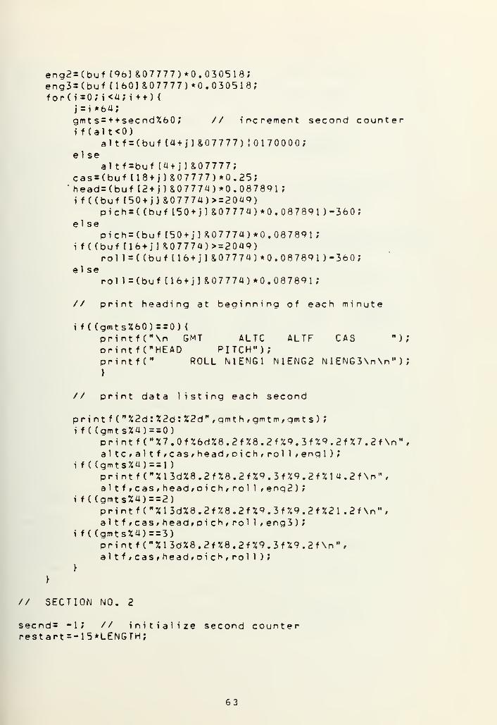
eng2=(buf ( 96 ]&07777)*0. 030518;eng3=(buf (160] &07777)*0. 030518 ;
for ( i=o; i<a;i++) 4
j = i *64;gmt s=ttsecnd%60 ; // increment second counteri f (al t<0)
altf = (buf(4+j]&07777) 10170000;el se
al tf=buf Cat j] &07777;cas=(buf [18tj] SO 7777)* 0.25;
'
head=(buf 12 tj]&07774)*0. 087891;if((buf(50tj]&0777a)>r2 0a9)
pich=( (buf[50tj] &0777a)*0. 087891 )-360;el se
pich = (buf (50 t j] &0 77 7a)* 0.08 7891
;
i f( (buf U6tj] £07774 )> = 2049)roll = ((buf (16tj ]&0 777a) *0. 08 7891) -360;
el seroll =Cbuf(16tj] &0777a)*0. 087891;
// print heading at beginning of each minute
i f
(
(gmts%60)= = 0)
{
printf("\n GMT ALTC ALTF CAS ");orintf ("HEAD PITCH");printfC ROLL N1ENG1 N1ENG2 N 1 ENG3\n\n" ) ',
}
// print data listing each second
printf("%2d:%2d:%2d M ,gmth,gmtm,gmts);i f (Cgmts%a)= = 0)
print f ("%7.0f%6d%8.2f%8.2f%9.3f%9.2f%7.2f\n H,
altC/altfrcas/headfpich/rol 1 * engl )
;
i f
(
(gmts%a)==l)p r i n t f ( " % 1 3d%8 . 2 f %8 . 2 f %9 . 3 f 7.9 . 2 f % 1 a . 2 f \n "
,
altf/caSfheadfOich,rol 1 > eng2 )
;
i f
(
(gmts%a)= = 2)
p r i n t f ( " % 1 3d%8 . 2 f %8 . 2 f %9 . 3 f 7.9 . 2 f %2 1 . 2 f \n ",
altf»cas/head»oich,rol 1 * eng3 )
;
i f
(
(gmts%a)= = 3)
print f ("%13d%8.2f%8.2f%9.3f%9.2f\n" ,
altfrcasfhead/oich,pol 1 );
}
// SECTION NO. 2
secnd= - 1 ; // initialize second counterrestart=-15*LENGTH;
63


seek ( f pi / rest art t 4 ) ; // rewind to start framewhileC C(secnd+1)/60)<LENGTH) <
read ( f p 1 # buf * 5 1 2 ) ; // read next data frame
// convert data to engineering units
gmth=(((bufU64]&0700)>>6)*10) + (buf[164]&0l7);gmtm=(((bufl36]&0700)>>6)*10)+(buf(36]&017);for(i=0;i<4; i + +) {
j=i*64;gmt s=++secnd%60 ; // increment second counterlng=((buf [43+j] &0 7777 ) *0
.
000508625 )- 1 .0833;for(m = 0;m<4;m + +) {
n = m* 16?verg[m]=((buftl2+n+j]&07774)*0. 00228883-3. 3755;latg[m}=( (buf tlU +ntj] & 077 7 4 ) *0 . 000508625) -1 .0833;}
// print heading at beginning of each minute
i f
(
(gmts%603==0) {
printf("\n GMT LONG VERG VERG");orintfC VERG VERG LATG LATG");printfC* LATG LATG\n\n");}
// print data listing each second
print f ("%2d:%2o:%2d%8.4f ", gmt
h
,gmtm, gmt s, 1 ng)
;
fop(m=o;m<a;m++)print f ("%8.4f ", verg [ml ) ;
for(m=0;m<4;m++)printf ("%8.4f", latgtm] )
;
printf ("\n");>
// SECTION NO. 3
secnd= -l; // initialize second counterrestart=-15*LENGTH;seek ( f pi , rest art , 4 ) ; // rewind to start framewhi le(( (secnd+1 )/60)<LENGTH) {
read ( f pi , buf » 5 1 2 ) ; // read next data frame
// convert data to engineering units
gmth=(((buftl64J&0700)>>6)*10)+(buffl64]&017);gmtm=(((buf(36]&0700)>>6)*10)+(buf(36l&017);f o r ( i = ; i < 4 ; i + ) {
64


j=i*64gmts=+elli=(e 1 ro=
(
rudl=(ail i=(ai ro=
(
f or (m=n=m*32rudu [m
}
+secnd%60; // increment second counter(buf(40+j]&07774)*0.0 3541)-72. 513176;(buf(7+j]&07774)*0.037474)-76.74 65;(buf [1 1 + jl &0 7 77 7)*0.0 32531 ) -66.6221 09;(buf(8+j]&07774)*(-0. 031206)) +6 3. 910161;(buf 139+ j 18,07777)* (-0.0397225)) +8 1*351 7;0;m<2;m + +) {
•
] =( (buf (26*n + j) &0 7774)* 0.0 325 31 ) -66.622 109;
// orint heading at beginning of each minute
i f
(
(gmts%60)==0) {
printf("\n GMTprintfC ELEVROprint f'C" A ILL I
>
TAT HSTAB ELEVLI");RUDUP RUDUP RUDLO");AILRO FLAPR3\n\n");
// print data listing each second
p r i n t f
i f ( (gmi f
el
hsf 1
pr i nt f
pr i nt f
pr i nt f
>
i f ( ( g m
i f
el
pri nt f
print f
pr i nt f
>
}
("%2d:%2o:ts%2)==0){((buf (54 + j
hsta=( (
(
*(-0.938seta=( (buf (5
ao=( (buf 13
("%15.3f%7(M %7.3f%7.("%7.3f%7.
ts%2)==l ) {
( (buf (54 1
j
tat=( (buse
tat=(buf(M %8.3f%14
(M %7.3f%7.
("7.7.3f%7.
%2d%gmth,gmtm,amts) ;
] &07777)>=2049)buf (54fj]&07777)*0. 087891)- 36 0)
967);
4+j] &0 7 777)* 0.08 7891)* (-0.938967);8+j]&07774)*0.087891)-180;. 3 f % 7 . 3 f
"
»hsta,elli»elpo);3f%7.3f " , rudu (01 , rudu tl) , rudl );
3f%7.3f\n" ,ai 1 i ,ai ro, f 1 ap) ;
1 &07777)>=102a)f(54+j]&07777) 10176 0)* 0.4 995 1171 ,*
(54 + j] 8,0 7 77 7)* 0.49951 171 ,*
.3fZ7.3f ,tat,eUi,elro);3f%7.3f " /rudu (01 , rudu (1) , rudl );
3f \n H, a i 1 i * a i ro)
;
// SECTION NO. 4
secnd = -W // initialize second counterrestart=-15*LENGTH;
65


seek ( f p
1
, rest art , 4) ; // rewindwhile(((secnd+l)/60XLENGTH)<
readCfpl »buf ,512) ; // read next
to start f rame
data f rame
// convert data to engineering units
gmth=(((buf[164]&0700)>>6)*10)+(buf[164]&0l7);gmtm=( ( (buf [361 &0700)>>6)*10) + (buf [36] &0 17)
;
f o r ( i = ; i < 4 ; i + + ) {
j=i*64;gmt s=++secnd%60 ; // initialize second countervhf l = (buf [8 + j] 8.02) >>l ;
vhf2=buf [8+j] &01 ;
s14r2=(buf [16+sl4rl=buf U6+jsiai l=(buf [28+sl412=buf [28 + j
si 21 l = (buf [40 +
s1212=(buf [44+
1 & 2 ) > > 1 ;
&oi;] &02)>>i;&oi;] &02)»i;] &02)»i;
// print heading at beginning of each minute
i f ( (gmts%60)==0)
{
ppintf("\n GMT . VHF1 VHF2 TRU1 TRD1 TRU2 M)
;
printf CTRD2 TRU3 TRD3 S4L1 S4L2 S2L1 S2L2");printfC S4R1 S4R2\n\n");
)
// print data listing each second
printi f ((g
t
t
pt
>
if (Cgt
t
pt
}
i f ( (gt
t
o
t
}
if((q
f (n %2d:%2d:%2d%5d%5d",gmth,gmtm,gmts,vhf 1 , vhf2) ;
mts%4)==0) {
rul = (buf [6] &02)>>1 ;
rdl=buf [6] &01;rint f
(
M %5a%5d%25d%5d%5d%5d%5d%5d\n",ru l,trdl, si 411 , si 412, sl211,sl212,sl4rl rS l 4 r2);
mts%4)==l )
{
ru2=(buf [70] &02)>>1
;
rd2=buf [70] &01;rint f ("%15d%5d%15d%5d%5d%5d%5d%5d\n",ru2,trd2,sl41 I,sl412,sl211,sl212,sl4rl,s14r2);
mts%4)==2) {
ru3=(buf [134] &02)>>1 }
rd3=buf [134] &01;r i n t f ( "X25d%5d%5d%5o%5d%5d%5d7.5d\n "
,
ru3,trd3,s!41 t, si 41 2, si 21 I,sl212,s14rl,s14r2);
mts%4)==3) {
66


print f ("%35d%5d%5d%5d%5d%5d\n H,
sl4UrSl412,s12U,sl212,sl4rl,s14r2);}
67


APPENDIX C
PROGRAM TO COMPRESS DATA
A. DATA.C DESCRIPTION
This routine was written in UNIX C and was designed to
access data anywhere on the DFDR data tape, compress it us-
ing a simple algorithm and then store the compressed data in
a file called "DFDR". By comparing the size (number of bits)
of the "DFDR" file to the tape file, the amount of compres-
sion can be determined. For example: If the compressed file
required 7188 8-bit bytes to record 10 minutes of data the
compression factor would be
12 x 64 x 60 x 10 Q ..
7188 x 8 "8 * 01
The user must determine the magnetic tape unit he is go-
ing to use (TAPEDRIVE) and the program must be recompiled
whenever this information is changed. The program will prompt
the user on the terminal for the number of the first frame of
DFDR data he wants to access (START) and the number of minutes
of data he wants to compress (LENGTH) .
The main program consists of four sections which corres-
pong to the four subframes of data contained in each frame
[Ref . 7] . The data is read from the tape, one frame at a
time, and placed in a buffer array. The parameters are pro-
cessed in the order they were recorded. If a parameter occurs
more than once in a frame a subroutine is called to carry out
its processing. These subroutines are identified with a "W"
68


followed by an octal code number which corresponds to the
parameter concerned.
Each parameter is processed using the following procedure.
The applicable bits for the parameter are removed from its
12-bit data word and if it contains more than six signifi-
cant bits it is divided into two parameters. This is the
case for all parameters except the discretes and Coarse Alti-
tude (ALTC) . The upper six bits are referred to as the
coarse parameter and the lower six as the fine. Their para-
meter names are suffixed with a "C" and "F" , respectively.
If the coarse parameter's value is different from its last
stored value the new value is stored along with its applicable
octal label. The value of the fine parameter is then compared
with its last stored value and if the absolute value of their
difference is greater than a predetermined tolerance, the new
value is stored along with its applicable octal label. The
fine parameter is also always stored when the coarse parameter
changes value. The sum of the differences between the succeed-
ing new parameter values and the parameter's last stored value
is recalculated. If the absolute value of this sum is greater
than the tolerance the new value is recorded.
Discrete parameters are packed into 6-bit groups. If a
discrete parameters new value is different from its last re-
corded value, the group is recorded along with its applicable
octal label
.
Whenever a parameter is stored, it is placed in the lower
6 bits of a 12-bit word. The upper six bits are a 6-bit octal
69


label which is used to identify the parameter in memory.
This is the same number which is used in identifying the sub-
routines. When four 12-bit parameter words are available
for storage, they are packed into three 16-bit memory words
and transferred to the file "DFDR" using the subroutine "Rite"
Since GMT does not include seconds, a second counter is
initialized whenever the minute parameter changes and is
incremented and recorded at the start of each subframe.
B. DATA.C PARAMETERS
The following is a list of parameters along with their
location in the 64 12-bit word DFDR data frame. Also shown
are the octal labels and code names for each parameter along
with the corresponding data word bits.
70


PARAMETER BITS WORD SUBFRAMES OCTAL CODE BITSNAME LABEL NAME
GMT (HOURS) 1-12 37 3 00 GMTH 1-12
GMT (MINUTES) 1-12 37 1 01 GMTM 1-12
MAGNETIC HEADING 3-12 3 1,2,3,4 03
04
HEADC
HEADF
7-12
3-6
ALTITUDE COARSE 1-12 23 1 05 ALTC 1-6
ALTITUDE FINE 1-12 5 1,2,3,4 06
07
ALTF
ALTFF
7-12
1-6
COMPUTED AIR SPEED 1-12 19 1,2,3,4 10
11
CASC
CASF
7-12
1-6
PITCH ATTITUDE 3-12 51 1,2,3,4 12 PICHC 7-12
13 PICHF 3-6
ROLL ATTITUDE 3-12 17 1,2,3,4 14
15
ROLLC
ROLLF
7-12
3-6
ENG1 THRUST (Nl) 3-12 33 1 16
17
ENG1C
ENG1F
7-12
1-6
ENG2 THRUST (Nl) 1-12 33 2 20
21
ENG2C
ENG2F
7-12
1-6
ENG3 THRUST (Nl) 1-12 33 3 22
23
ENG3C
ENG3F
7-12
1-6
LONGITUDINAL ACCEL 1-12 44 1,2,3,4 24
25
LONGC
LONGF
7-12
1-6
71


PARAMETERNAME
BITS WORD SUBFRAMES OCTAL CODE BITSLABEL NAME
26 VERGC 7-12
60 VERGF 3-6
26 VERGC 7-12
61 VERGF 3-6
26 VERGC 7-12
62 VERGF 3-6
26 VERGC 7-12
63 VERGF 3-6
30 LATGC 7-12
64 LATGF 3-6
30 LATGC 7-12
65 LATGF 3-6
30 LATGC 7-12
66 LATGF 3-6
30 LATGC 7-12
67 LATGF 3-6
32 TATC 7-12
33 TATF 1-6
34 HSTAC 7-12
35 HSTAF 1-6
VERTICAL ACCEL
LATERAL ACCEL
TOTAL AIR TEMP
3-12 13 1,2,3,4
3-12 29 1,2,3,4
3-12 45 1,2,3,4
3-12 61 1,2,3,4
3-12 15 1,2,3,4
3-12 31 1,2,3,4
3-12 47 1,2,3,4
3-12 63 1,2,3,4
1-12 55 2,4
HORIZONTAL STABILIZER 1- 12 55 1,3
72


PARAMETERNAME
BITS WORD SUE-FRAMES OCTALLABEL
CODE BITSNAME
ELEVATOR LT-INBD 3-12 41 1,2,3,4
ELEVATOR RT-OUTBD 3-12 8 1,2,3,4
RUDDER POSITION,UPPER
RUDDER POSITION,LOWER
AILERON POSITLT-INBD •
AILERON POSITRT-OUTBD
3-12 27 1,2,3,4
3-12 59 1,2,3,4
1-12 12 1,2,3,4
3-12 9 1,2,3,4
1-12 40 1,2,3,4
RIGHT HAND FLAP NO. 3 3-12 39 1,3
36
37
40
41
42
43
42
57
44
45
46
47
50
51
52
53
ELLIC 7-12
ELLIF 3-6
ELROC 7-12
ELROF 3-6
RUDUC 7-12
RUDUF 3-6
RUDUC 7-12
RUDUF 3-6
RUDLC 7-12
RUDLF 1-6
AILIC 7-12
AILIF 3-6
AIROC 7-12
AIROF 1-6
FLAPC 7-12
FLAPF 3-6
73


PARAMETERNAME
VHF 1 KEYING
VHF 2 KEYING
ENG1 THRUST REV UNLOCK
ENG1 THRUST REV DEPLOY
ENG2 THRUST REV UNLOCK
ENG2 THRUST REV DEPLOY
ENG3 THRUST REV UNLOCK
ENG3 THRUST REV DEPLOY
SLAT 4 RT-OUTBD (MSB)
SLAT 4 RT-OUTBD (LSB)
SLAT 4 LT-OUTBD (LSB)
SLAT 4-LT-OUTBD (MSB)
SLAT 2 LT-INBD (MSB)
SLAT 2 LT-INBD (LSB)
ITS WORD SUBFRAMES OCTALLABEL
CODENAME
1 9 1,2,3,4 54 VHF1
2 9 1,2,3,4 54 VHF2
1 7 1 55 TRU1
2 7 1 55 TRD1
1 7 2 55 TRU2
2 7 2 55 TRD2
1 7 3 55 TRU3
2 7 3 55 TRD3
1 17 1,2,3,4 56 SL4R1
2 17 1,2,3,4 56 SL4R2
1 29 1,2,3,4 56 SL4L2
2 29 1,2,3,4 56 SL4L1
2 41 1,2,3,4 56 SL2L1
2 45 1,2,3,4 56 SL2L2
VHF1 and VHF2 are combined in the program as variable VHF12
and are stored in the lower two bits of a word with the
octal label 54. TRUl, TRDl, TRU2, TRD2, TRU3 and TRD3 are
combined in the program as variable TRUD and are stored in
the lower six bits of a word with the octal label 55.
SL4R1, SL4R2, SL4L2, SL4L1, SL2L1 and SL2L2 are combined in
the program as variable SLAT and are stored in the lower
six bits of a word with the octal label 56.
74


G, DATA.C LISTING
ft define LENGTH 151ft define TAPEDRIVE "/dev/mtint f pi ,
f
p2,buf [2561 , i , t e^oint gmt h , gmt m , gmt s , headc , heint pi chc , pi ch f , roll c , roll
f
int eng3f , 1 onqc , 1 ongf , vergeint hstachstaf;int ell i c ,e 1 1 i f ,e1 roc ,e 1 rofint ai 1 i c , ai 1 i f , ai roc , ai rofint n00,n01 ,n02,n03,n04,n05int nl5,nl6,nl7,n20,n21,n22int n32,n33,n34,n35, n36,n37int n47,n50,n5l ,n52,n53,n54int heads , a 1 t f s , cass , pi chs
,
int vergs , 1 atgs , t at s , hst as
,
int airosrflaDs;
1M
, pack [4] , n, flag, El, E2, START;adf , a 1 teal t f , a 1 tff »casc;casf?,englc,englf,eng2c,eng2f,eng3c;, vergf , 1 at gc , latgf,tatc,tatf;
» ruduCfPuduf > rudlCf rudl f?
,f1apc,flapf,vhfl2,trud,s1at;,n06,n07,nl0,ntl,nl2,nl3,nl4;,n23,n24,n25,n26,n27,n30,n3i;, n 40,n41,n42,n43,n44,n45,n46;,n55,n56,'poI 1 S,engls,eng2s,eng3s, longs;el 1 i s , el ros,rudus,rudl s ,ai 1 is;
// This routine will' access data on the DFDR tape,// compress it using a simple algorithm and// store the compressed data in the file "dfdr".
// TAPEDRIVE indicates the magnetic tape unit to be used// LENGTH indicates number of data frames to be compressed
mai n ( ) {
printf ("START = " ) ; //scanf ("%4d\n",&START) ;
fp2=creat ("dfdr", 0600);fpl=open(TAPEDRIVE,0);seek(fpl, START, 4) ; //for(i=l,* i<LENGTH; i + + ) {
read(fpl ,buf ,512)
;
// SUBFRAME NUMBER 1
first data frame to be compressed
// c reat e a
// open maglocate first
file called "dfdr"t ape filedata f rame
// read next frame of data
w2();w3(2);w6(4) ;
/* thrust reverser engl */
temp = buf (6] &03;i f
(
(trud&060) ! = (temp<<4)){trud=(trud&0 17) ! (temp<<4);pack In) =t rudl 05500;if(+ + n = = 4) riteO;n55++;>
75

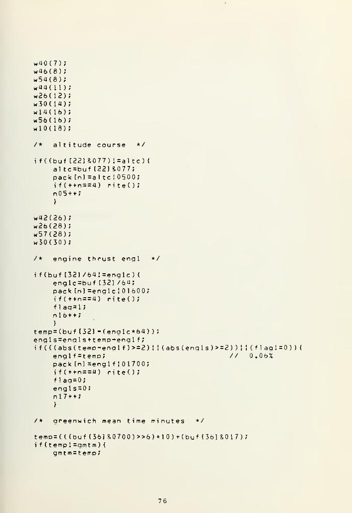
w40(7);wa6(8);w5a(8);w44(l l )
;
w26(12);w30(ia);w 1 a ( 1 6 )
;
w56(16);w l o ( 1 8 ) ;
/* altitude course */
i f ((buf C22] 8.077) i=al tc) {
al tc=buf 122) &077;pack [n] =al tc 10500;if(+ + n = = a) riteO;n 5 + + ;
}
w42(26);w26(28);w57(28);w30(30);
/* engine thrust engl */
i f (buf 132] /6a'=englc) <
englc=buf [32] /64;pack tn] =englc J01600;if(+ + n = = a) riteO;f 1ag=l;n 1 6 + + ;
}
temp=(buf (32]-(englc*64));enqls=enals+temp-enql f ;
i f (((abs(temp-englf )> = 2) ! ! ( abs (eng I s ) > = 2 ) ) } { ( f 1 agl=0) )<englf=temo; // 0.06%pack [n] =engl f ! 01700;if(t + n = = 4) riteO;flag=0;engl s=0
;
n 1 7 + + ;
>
/ * greenwich mean time minutes */
temp=( ((bufI36]&0700)>>6)*10)+(buft36]&017);i f ( temp 1 =gmt m ) {
gmtm= t emp
;
76


pack [n] sgmtm ! 0100;if(+tn==4) riteO;gmt s=0;n If + ;
>
w52(38)*50(39)w36(40)w58(a0)w2a(a3)w26(44)w59(aa)w30(46)wl2(50)w3a(5a)w42(58)w26(60)w30(62)
// SUBFRAME NUMBER 2
w2();w3(66);w6(68)
;
/* thrust reverser eng2 */
temp=buf [70] &03;i f ((trud&0i4) ! = (temp<<2) )
{
trud=(trud&063) ! (temp<<2) ',
pack [n] =trud! 05500;if(t+n==4) riteO;n55+f ;
>
w40w46w5aw44w26w30wlaw56wlOw42w26w57w30
(71)(72)(72)(75)(76)(78)(80)(80)(82)(90)(92)(92)(94)
77


/* engine thrust eng2 */
i f (buf [96] /641=eng2c)
{
eng2c=buf C96] /64;pack In] =eng2c ! 02000;if(+ + n = = 4) riteO;f lag=l;n20t+;}
temp= (buf [96] -(eng2c*64)
)
eng2s=eng2s+temp-eng2f
;
i f ( ((abs(temp-ena2f )> = 2)
!
eng2f = t empjpack [n] =eng2f !02100;if(++n==4) riteO;f 1ag=0;eng2s=0
;
n21f+;>
(abs(eng2s)>=2) ) ! ! ( f
1
agi =0 ) )
<
// 0.0 6%
w50(w36(w58(w2a(w26(w59(w30(wl2(w32(wa2(w26(w30(
103)104)104)107)108)108)110)114)118)122)124)126)
// SUBFRAME NUMBER 3
w2();w3(130);w6(132);
/* thrust reverser eng3 */
temo=buf [134] &03;i f
(
(trud&03) i=temp) {
t rud=(t rud&074)
!
temp;pack [n] =t rud! 05500;if(++n = = 4) riteO;n55++;}
w40(135);
78


wa6(w54(w4a(w26(w30(wia(w56(wlO(*42(w26(w57(w30(
136)136)139)140)142)iaa)144)146)15a)156)156)158)
/* engine thrust eng3 */
i f (buf (160] /64'=enq3c) {
eng3c=buf (160] /64;pack tn] =eng3c J 0220 0;
if(++n==4) riteOJf 1ag=l;n22++;}
temp=(buf (160) -Ceng3c*64) )
;
eng3s =eng3s+temp-eng3* ?
i f ( ( (abs(temo-eng3,f )> = 2)eng3f =t emp;pack In] =eng3f
!
02300;if(++n==4) riteO;f
1
ag=0;eng3s=0 ;
n23++;)
(abs(eng3s)> = 2) ) J J ( f 1 ag I =0 ) )
{
// 0.06%
/* greenwich mean time hours */
temp=
(
((buf[164]&0700)>>6)*10)+(buf(164]&017);i f ( temp ! =gmt h
)
{
gmt h = t emp
;
pac k [n] =gmt h ;
if( + fn = = a) riteO;n00++;>
w52(166)w50(167)w36(168)w58( 168)w24(171)w26(172)w59(172)
79

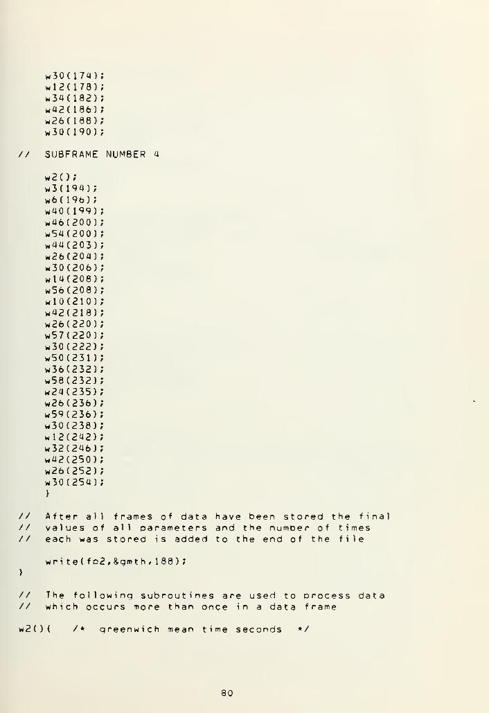
w30(174)wl2(178)w34(182)w42C186)w26(188)w30(190)
// SUBFRAME NUMBER a
w2()w3(lw6( 1
w40(w46(w54(w44(w26(w30(wta(w56(wlO(w42(w26(w57(w30(w50(w36(w58(w24(w26(w59(w30(wl2(w32(w42(w26(w30(>
94);96);199)200)200)203)204)206)208)208)210)218)220)220)222)231)232)232)235)236)236)238)242)246)250)252)254)
// After all frames of data have been stored the final// values of all parameters and the number of times// each was stored is added to the end of the file
}
wri te(fp2f &gmth, 188)
;
// The following subroutines are used to process data// which occurs more than once in a data frame
w2(){ /* qreenwich mean time seconds */
80


pack t
i f (+ +
n02 + +
}
w3(m){ /
temp =
i f (teh
Pi
f
n
}
temp =
headsif (((
h
Pi
f
h
n
}
}
w6(m){ /
i f (bua
Pi
f
n
}
temp =
al t f s
i f (((a
Pi
f
a
n
>
>
wlO(m) { /
i f (buc
Pi
f
n
] =gmts++ ! 0200;= = 4) riteO;
n] =
n
* magnetic headinq */(but Im] &07774)/64;mp ! =headc ) {
eadc=temp;ack In] =headc ! 0300;f(++n==4) riteO;lag=l;03 + + ;
Cbuf Cm] &0 7 774)-(headc*64) ;
=heads+temp-headf;abs(temp-headf )> = 8) ! !
eadf =temp;ack In] =headf J0400;f(t + n==4) riteO;lag=0;eads=0;04 + + ;
* al t i t ude fine */f [m] /64J=al tf ) <
1 tf=buf lm] /64;ack [nl =al tf ! 0600;f(++n==4) riteO;1ag=t
;
06 + + ;
buf Cm] -(al t f *64) ;
= al t f s + temD-al t f f ;
abs(temp-a1 t f f )> = 5) !
1 t f f = temo;ack tn] =a1 t f f ! 0700;f(+tn = = 4) riteO;1 ag=0;i tfs=o;7 + + ;
(abs( heads )>=8) ) I ! ( f 1 ag i =0 ) )
{
// 0.70 deg
(abs(a) t
f
s)> = 5)) ! ! (flag 1=0) )
{
// 5 feet
* computed air speed */f lm] /64i=casc) {
asc=buf fm] /64;ack (n] =casc ! 01000;f( + + n = = 4) riteO;1 aq=l ;
10 + +;
81


>
temo= (bucass=casi f (
(
(abscas f
packif (flagcassnll +
>
}
wl2(m){ /*temp= (bui f ( t emp i
pi chpackif ( +
flagnl2 +
}
temp = (bupi chs = pi
i f (
(
(abspi chpacki f (flagpi chnl3 +
}
>
wl4(m)< /*
temp = (bui f ( t emp
1
rol 1
pac k
i f ( +
flagnl4 +
}
t emD= (buro 1 1 s=roi f (
(
(absrol 1
packi f (flagrol 1
nl5 +
*/
f [ml -(casc*64) ) ;
s*t emp-cas f ?
(temo-casf )> = a) J
=temp;In] =casf 101100;+n==4) riteO;= 0;= 0;+ ;
oitch at t i t udef (ml &07774)/64;=pi chc )
<
C=temp;In] =pichc!01200;n==4) riteO;= i;
+ ;
f (ml &0 7774)-(oichc*64) ;
chs + t emo-pi ch f
;
(temp-pichf )>=4)f =temp;[n] =oichf 101300;+ n = = 4) riteO;= 0;
s = o;
;
( abs (cass )> = 4)) J J (f lag!=0)){// 1 knot
! (abs(pichs)> = 4) )• J (f lag 1=0)) {
// 0.35 deg
roll attitude */
f Cm] &07774)/64;= rol lc) {
c=t emp;tn] =rol lc J01400;*n==4) riteO;= i;
+ ;
f [ml &07774)-(r O l 1c*64) ;
1
1
s+temo-rol 1 f ;
(temo-pol 1 f )> = 8) i ! (absCrol 1 s)> = 8) ) i ! (f lag!=0) ) <
f=temp; // 0.70 deaIn] =rol 1 f 101500;n = = 4) riteO;
= 0;
s = o;
+ ;
82


>
}
w24(m){ /* longitudinal acceleration */
i f (buf tml /64J = lonqc) {
1 onqc=buf [ml /64;pack [nl =longc 102400;if(++n==4) riteO;f 1ag=l;n24++;>
temp=(buf [ml-(longc*64));longs=longsttemp-1ongf;i f (( (abs(temp-longf )> = 4) ! ! ( abs ( 1 ongs ) > = a ) ) ! ! ( f 1 ag i =0 ) ) {
longf=temp; // 0.002 gpack tnj =longf 102500;if(++n==4) riteO;f lag=0;1 ongs = ;
n25++;}
}
w26(m){ /* vertical acceleration */
temps (buf [m)&07774)/64;i f ( temp 1 =vergc ) <
vergc=t emp;pack In] =vergc J02600;if(+ + n = = 4) riteO;f lag=l;n26++;}
temp=(buf Cm] &0 7 774) -
(
verge *64 ) ;
verqs=vergs+temp-vergf;i f (((aos(temo-vergf )>=12) I ! ( abs ( vergs ) > = 1 2 ) ) J \ ( f 1 ag ! =0 ) ) {
vergf =temp;i f ((m%64)==12)
oack [n] =vergf ! 060 00;i f
(
(m%64)==28)pack(nl=vergf!06100;
i f
(
(m%64)r = a4)pack tn] =vergf ! 06200;
i f
(
(m%64)==60)oack [nl=vergf! 06300;
if(+ + n = = 4) riteO;f 1 ag = 0;
vergs = ;
n27++;}
// 0.0275 g
>
w30(m){ /* lateral accelerationtemo=(buf tm]&07774)/64;
*/
83

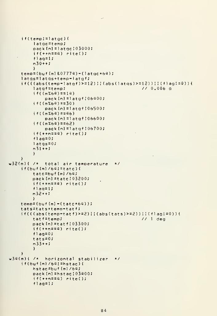
i f
(
temp i = 1 atgc ) {
1 atgc=t emp;pack [n] =1 atgc
!
03000;if(++n==4) riteC);f 1ag=l;n 3 + + ;
}
temD=(buf tm]&07774)-(1atgc*64);1 atgs=1 atgs+temp-1 atgf ;
i f (((abs (temp-la tgf)>= 12) ! ! ( abs ( 1 at gs ) >= 1 2 ) ) ! ! ( f 1 ag i =0 ) )
{
1 atgf =t emp;i f ( (m%64)==14)
pack [n] =1 atgf
!
06400;i f ( (m%64)= = 30)
pack [n] =1 atgf
!
06500;i f C (m%64)r=46)
pack [nj =1 atgf
!
06600;i f ((m%64)==62)
pack [nJ =1 atgf
!
06700;if(+ + n = = 4) piteOJf lag=0;1 atgs=0;n31++;>
// 0.006 g
>
w32(m){ /* total air temperaturei f (buf [m] /641=tatc) {
tatc=buf (ml /64;pack In] =tatc ! 03200;if(++n==4) riteO;f lag=l;n32++;}
temo=(buf tml -Ctatc*64)) ;
tats=tats+temp-tatf;i f ( ( (abs (temp-tat f )> = 2)
tat f = t emp;pack [n] =tat f
!
03300;i f (+ + n = = 4) ri te( ) ;
f lag=0;tats=0;n 3 3 + + ;
>
>
w34(m){ /* horizontal stabilizeri f (buf (ml /64»=hstac) <
hstac=buf (ml /64;pack [n] =hstac ! 03400;i f (++ n ==4) ri te( ) ;
f lag=l;
*/
! ! (abs(tats)> = 2)
)
! ! (f
1
ag!=0)) {
// 1 deg
*/
84

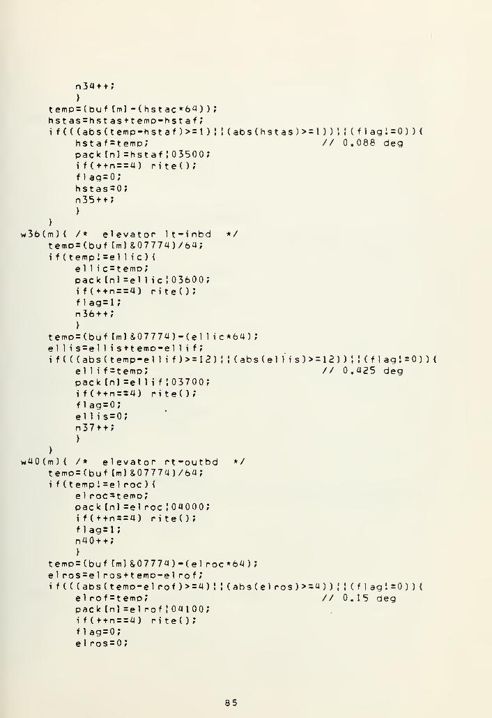
n34++;>
t emp =
hst asif (((
h
(abs(hstas)>=l))ii(flagi=on<// 0.088 deg
}
w36(m) {
t emp =
if (tee
Pi
f
n
}
temp =
ell isi f (((
e
Pi
f
e
n
}
}
w40(m){ /
t emp =
i f (tee
Pi
f
n
>
t emp =
e! posi f (((
e
pi
f
e
*/
(buf (m] -(hstac*6a) )
;
=hstas+temp-hstaf;abs( temp-hstaf )>=1 )
!
st af =temp;ack [nl =hstaf ! 03500;f(++n==4) riteO;1ag=0;stas=0;35 + + ;
* e 1 evat or 1t -i nbd
(buf (ml &07774J/64;mp
!
=el 1 i c ) {
1 1 i c=t emp;ack [nl =el lie! 03600;f(+ + n = = 4) riteO;lag=i;36 + + ;
(buftm]&07774)-(ell ic*64);= el 1 i s + temp-el 1 i f
;
abs( temp-el 1 i f ) >= 1 2 ) ! ! ( abs ( e 1 l" i s ) >= 1 2 ) ) ! ! ( f 1 ag ! =0 ) ) {
1 1 i f = temp; // 0.425 degack [nl =el 1 i f 103700;f(+ + n = = 4) piteO;lag=0;1 1 is = 0;
37++;
* elevator Pt-outbd */
(buf (ml &07774)/64;mp i =el poc ) (
1 POC=t emp;ack [nl =el poc J04000;f(f + n = = 4) riteO;lag=l;4 + + ;
(buf(m]&07774)-(elpoc*64);= e 1 pos+temp-el pof;abs (temp-el pof)>=4)::(abs(elpos)>=4))!!(flagi=0)){1 pof =temp; // 0.15 degack [nl =el pof ! 04100;f(f + n = = 4) PiteO;lag=0;I posse-
ss


>
w42(mt
i
){ /
emp =
f (tep
Pi
f
"n
>
emp =
udusf (((
r
i
* rudder position upoer(buf [ml &07774)/64;mp ! =ruduc )
<
uduc=t emp;ack In] sruduc 1042007f(+t ns=4) piteO;lag=l;42 + + ;
*/
(buf t
= ruduabs(tuduf =
f ( (m%pa
f ((m%pa
f (t + n
1ag =
udus =
4 3 ;
ml &0s + teemp-t emp64) =
ck tn
64) =
ckln= = 4)•9
o;
7774)-(ruduc*64) ;
mp- rudu f
?
ruduf )>=12) ! ! (abs(rudus)>=12)) \ ! ( f 1 ag i =0 ) )
{
; // 0.39 deg= 26)J =ruduf ! 04300;= 58)] =puduf !05700;PiteO;
w44(mi
1 ower */){ /* rudder positionf (buf tm) /6.41 = pudlc) {
pudlc=buf (ml /6a;pack'Cn] =rudlc!04400;if(t+n==4) piteO;f lag=l;n44++;>
temp=(buf (m]-(pud1c*64));rual s=rud
1
s+temp-rudl f;
i f (((abs(temp-pudl f )> = 4) |
• (abs(rudl s)>=4))|!(flagi=0)){pudlf=temp; // 0.13 degpack tn] =pudl f 104500;if( + + n = = 4) piteO;f lag=0;pudl s=0;n45++;>
>
w46 (m
t
i
){ /* ailepon positionemo=(buf (ml 8,07774) /64;f ( temp I =ai 1 i c ) {
a i 1 i c = t emp;pack [n] =ai He ! 04600;
1 t-i nbd */
86


tea i
i f
if (flagn46 +
>
mo= (bu1 i s = ai
( ( (absail i
packif ( +
flagai 1 i
n47 +
>
+ n = = 4) ri te( )
;
= i;
*;
f (ml &07774)-(ai 1 ic*6a) ;
1 i s + temp-ai 1 i f ;
(temp-ai 1 i f )>=16) !
f =temp;(nJ =ai 1 i f J04700;+n==4) riteO;= 0;
s = o;
+ ;
CabsCai lis )>=16)) !
!
(flag! =0))<// 0.499 deg
>
w50(m)i f
teai
i f
>
w52(m)tei f
tef 1
i f
{ /* aileron position rt-outbd */
(buf [m] /64!=ai roc )
<
ai roc=buf Cm] /64
;
pack (nJ =ai roc
!
05000;if(un = = 4) riteC);f lag=l;n 5 + + ;
>
mp=(buf(m]-(airoc*64));ros = ai ros+temp-ai rof;(((abs (temp-ai rof ) > = 1 ) J ! (abs ( a i ros ) >= 1 ) ) ! I ( f 1 ag ! =0 ) )
{
airof=temo; // 0.04 degpack tn) =ai rof ! 05100;i f (f + n = = 4) ri te( )
;
f lag = 0;
a i ros = ;
n51++;}
{ /* right hand flap no. 3 */
mo=(buf [ml &07774J/64;( temp 1 = f 1 ape ) {
f 1 aDC = t emp;pack [n] =f lapc ! 05200;if(+ + n = = 4) riteO;f lag=l ;
n52++;>
mp=(buf (ml&07774)-( f lapc* 64) ;
aps=fl aps+temp-fl apf;( ( (abs(temp-f lapf )> = 4) ! ! (abs ( f 1 aps ) > = 4 ) ) ! ! ( f 1 ag I =0 )
H
f1aof=temp; // 0.35 degpack [n] =f lapf 105300;if(++n = = 4) riteO;f laa=0;
87


f 1 aps=0;n53++;>
>
*/
2105400;i t e ( )
;
74) | temp;! 05600;i te()
;
w54(m)< /* vhf 1 &
temp = buf tm] &03;i f (tempi=vhf 12) <
vhf 12 = t emp;pack [n] = vh f 1
if(++n==a) r
r»54 + + ;
}
>
w56(m){ /* slat a rt-outbd */temp =buf tm] &03;i f (temp!=(slat&03) )
<
si at=(sl at&Opack fn) =s 1 atif(++n==4) r
n56++;>
>
w57(m){ /* slat 4 lt-outbd */
temp=buf [m] &03;i f
(
(temp<<4) ! = (ssi at=(sl at&Opack tn] =s 1 atif(+tn==4) p
n56++;>
>
w58(m){ /* slat 2 lt-inbd */temp = buf (ml &02;i f (
(
temp<<2) i = (s
si at=(sl at&Opack [n] =s 1 atif(++n==4) r
n56 + +;
>
>
w59(m){ /* slat 2 lt-inbd */temp=buf [ti] &02;i f ( (temp<<l ) I = (s
si at=(sl at&Opack [n] =s 1 atif(++n==4) r
n56++;}
>
lat&060) )
{
17) ! (temp<<4) ;
! 05600;i t e ( ) ;
lat&OlO) )
{
67) ! (temp<<2) ;
105600;i t e ( ) ;
lat&04) )
{
73)
!
(temp<l )
;
J05600;i t e ( ) ;
88


// This subroutine is used to oack// into 3 16-bit words
4 12-bit words
ri te() {
pack [0] =(pack [0] <<4)
J
(pack Cll >>8) ;
pack 111 =(pack (U <<8)
!
(pack [2] >>a);pack (2] =(oack 121 << 1 2) ! pack [3] ',
wri te(fp2/pack,6) ;
n = 0;
>
89


APPENDIX D
PROGRAM TO RECOVER AND LIST COMPRESSED DATA
A. RECOV.C DESCRIPTION
This routine was written in UNIX C and was designed to list
the compressed data in a standard format. It will access the
compressed data from the file "DFDR" , convert it to engineering
units and format it for output. The output may be displayed
immediately on the terminal screen or directed to an output
file for later display, printing, etc.
The user must determine the number of minutes of data he
wants to list (LENGTH) and the program must be recompiled
whenever this information is changed.
The main program consists of four sections which correspond
to the sections of the parameter listing which is produced.
The sections are divided into" cases" which perform the calcu-
lations required to recover the compressed data. At the beginning
of each section the compressed data file is opened and the
data is read three 16-bit words at a time. Subroutine
"UNPACK" is then used to convert the three 16-bit words of data
into four 12-bit words. The upper six bits of each 12-bit word
is the corresponding parameter's octal label which is used to
identify the "CASE" which corresponds to it.
The compressed data file is organized so that time in
seconds will be recorded at the beginning of each second of
data. When the second parameter (GMTS) is detected, the para-
meters for the section concerned are converted into engineering
units and formatted for output, a subframe (or second) at a
90


time. The parameters which had been divided into coarse and
fine, by the data compressing program DATA.C, are first added
together. The conversion equations and output format are the
same as were used in ORIGIN. C. If a parameter did not change
during a one second interval, its previous value is used. In
this way redundant data is recovered and listed.
The "second" counter is initialized at the start of each
section and incremented in each subframe. It is not used to
provide time in seconds since GMTS is available, but it is
used to determine when the correct amount of data has been
recovered
.
Processing in a section continues until the end of the
requested data period. The compressed data file is then re-
opened and processing continues until all sections have been
completed
.
Listings produced using this program can be seen in
Appendix F.
91


B. RECOV.C LISTING
#define LENGTH 3
int f p 1 r bu f [ 4 ] * m / i , j »Dara»aiithfq(ntmfamts»secndf al t >al tf ;
int altfffCasC;casffheadc»Headf»Dichc»Dichf,rol lc»rol 1 f ;
i nt englc * enql f * ena2c , ena2 f , enq3c * enq3f , 1 ongc
;
int 1 ongf t verge #1 atgc # t ate * tat f
»
Hstacr hstaf #el 1 i c#ell t f
r
int el rocrel rof#ruduc/rud1c»rudl f , a i 1 i c / a i 1 i f > a i POC>ai rof ;
int flapc/ flapfrvhflrvhf2ftrul#trdl#tpu2ftpd2*tru3/tpd3;int Sl411,sl412,s1211,sl2l2,sl4 r l,sl4r2;float alti ra1tC/cas/Head»pich,rol 1 renql,enq2fenq3,1nq;float tatvhstarflaprel 1 i f el r o > r u d 1 » a i 1 i f airo;float 1 atg [41 ;
float verg fa]
;
f 1 oat rudu f 21 ;
// This routine will access data from the compressed// data file " D F D R "
> convert it to enqineerinq units// and format it for output.
// The output may be displayed immediately on the// terminal or directed to an outDut file ^or later// display/ printinq etc.
// LENGTH indicates the number of minutes of data
m a i n ( ) {
// SECTION NO. 1
f pi =open
(
M df dr" , ) ; // ooen comoressed data fileseend--? // initialize second counterwhi le( (secnd/60)<LENGTH) {
read ( f p 1 » bu
f
* 6 ) ; // read block of 3 16-bit wordsunpackO; // unpack aata into 4 12-bit wordsfor(m=0;m<4;m*+) {
oara =bu f [ml &07700 ; // remove parameter octal labelswitchCparaH // use data label to select casecase 0000:
gmth=buf [ml &077;break ;
case 0100:gmtm = buf fm] &077;break;
case 0200:qmts = buf [ml 8,077;
// convert data to enaineerinq units
i f (al tc<0) {
92


al
al
>
el se <
al
al
>
Cc= (
oi
Di
cas =
headif ((
t=(altf+altff ) !01 70000;ti=al tc+4096.0;
t=a1 tf+al tff ;
t i =al tc;
asc+casf ) *0.25;hesdct Head f ) * 0.0 8 7891
;
chc+pichf )>=20a9)ch=((Dichc+Dichf)*0. 087891 )-360;
e 1 se
i f ((
el se
oich=(Dichc+oichf)*0. 087891;pol lc+rol 1 f )>=20a9)rol 1 = ( (rol lc + rol 1 f ) *0 . 08 789 1) -36 ;
rol l=(rollc+rol I f )*0. 8 7891
;
engl=(enalc+engl f)*0. 030518;ena2=(eng2c+ena2f ) * 0.0 3 0518;eng3=(ena3c+enn3f )* 0.0 3 0518;
// orint heading at beginning of each minute
i f ( (secnd%60)==)
{
printf( H \n GMTprintfC PITCHppintf ("\n\n");
>
flLTC ALTF CAS HEAD");ROLL N1ENG1 N1ENG2 N1ENG3");
// orint data listing each second
i f (secnd> = 0)
{
print f ("% 2d: X 2d: %2d"
,
gmth,amtm,gmts);i f C(amts%4)==0)printf ("27.0fX6d%8.2f%8-2f%9.3f%9.2f%7.2f\n w
,
a1ti>alt,cas/head/pich,rol1*enql);i f C (amts%4)==l)
o r i n t f C " % 1 3d*8 . 2 f %8 . 2 f %9 . 3 f %9 . 2 f % 1 a . 2
f
\ n "
/
al t/caS/head»oich, rol 1 ,eng2)
;
i f C(gmts%4)= = 2)printf("%13d%8.2f%8.2f%9.3f%9.2f%21.2f\n",altfCaSfheadrpichrrol 1 > eng3 )
;
i f C (amts%U)= = 3)
d r i n t f f" X 1 3d** 8 . 2f %8 . 2 f %9 . 3 f %9 . 2 f \n " ,
al t/cas/head,picH f rol 1 ) ;
>
secnd++; // increment second counteri f ( (secnd/60)= = LENGTH) m = 4; // look for end of LENGTHbreak ;
case 0300:
93


headc=(buftml&077)*6U;break ;
case OaOO:headf=buf [m] &077;break ;
case 0500:i f (Cbuf [m] &077)>=32)
altc = ((buf[m]8,077)!0l77 7a0)*a096.0;e 1 se
a1tc=(buf[m]&077)*a0<?6.0;break ;
case 0600:a) tf=(buf tm] *077)*64;break ;
case 0700:al tf f=buf [ml %077;break ;
case 01000:casc = (buf [m] *077)*64?break;
case 01100:casf=buf [ml &077;break ;
case 01200:pichc=(buf fml &077)*64;break ;
case 01300:Dichf =buf fm] %077;break
;
case 01400
:
rol lc=Cbuf [ml &077)*64;break ;
case 01500:-pol 1 f=buf Cm] R077;break ;
case 01600:englc=Cbuftm1&077)*64;break ;
case 01700:engl f =buf lm] &Q77;break ;
case 02000:eng2c=(buf [ml&077)*64;break ;
case 02100:eng2f=buf [ml X077;break;
case 02200:eng3c = (buf fm]&077)*6a;b reak ;
94


case 02300:eng3f =buf [m] &077;break ;
}
>
}
// SECTION NO. 2
f p 1 =open C "df dr
"
, ) ; // reopen compressed data filesecnd= -l; // initialize second counterwhi le( (secnd/60)<LENGTH)
{
read(fpl#buff6); // read block of 3 16 -bit wordsunpackO? // unoack data into 4 12-bit wordsfor(m = 0;m<4 ;(*• + ) {
para=bu f f m] &0 7700 ? // remove parameter octal labelswitch(para)< / / use label to select casecase 0000:
gmth=buf (ml &077;break ;
case 0100:gmtm = buf fml &077;break
;
case 0200:gmts=buf [ml 8,077;
// convert data to enaineerina units
lna=( (longc+longf )*0.0 00508625) -1 .0833;
// orint heading at beginning of each minute
i f ( (secnd%60)==)
{
printf("\n GMT LONG VERG VERG VERG " ) ;
printf ("VERG LATG LATG LATG LATG\n\n M);
>
// orint data listing each second
i f Csecnd> = 0)
{
print f ("%2d:%2d:%2d%8.4f " , gmt h , gmt m , gmt
s
, 1 ng )
;
f o r ( j = o ; j < a ; ] + +
)
orintf ("?.8.4f ",verg [j] ) }
f o r ( j = } j < a ; j + +
)
orintf ("7.8. af, latqCjl );
p r i n t f ( " \ n " ) ;
f o r ( j = ; j < 4 ; j + + )
verg C j
1
=verq T31 ;
for( j=o; j<a; j + + )
latg[j]=latqr31;
95


}
secnd++; // increment second counteri f
(
(secnd/60)==LENGTH) m = 4; // look for end of LENGTHbreak ;
case 02400:longc = (buf (ml&077)*64;break;
case 02500:longf =buf [ml *077;break ;
case 02600:vergc=(buf (m18,077)*64;break ;
case 03000:1 at gc=(buf[m] 8,077) *64;break ;
case 06000:for( j=0; }
<4; j+ + )
verg(jl =( ( (buf (ml &0 7 7
)
+verac ) *0 . 022*88 ) -3 . 3755
;
break ;
case 06100:for( j=l ; j<4; j++)verg(jl=(((buf(ml &0 7 7 ) +verqc ) *0 . 0228 88 ) -3 . 3 755 ,*
break ;
case 06200:for( j =2; j<4; ) ++)vergf j] =(( (buf (ml 8,0 77 ) t verge ) *0 . 0022888 ) -3 . 3755 ;
break ;
case 06300:vergC31 =C((buf rml 8,0 7 7
)
+verac ) *0 . 0228 88 ) -3 . 3755
;
break ;
case 06400:for ( j=0; j<4; j++)latg(jl=(((buf(ml&077)+latac)*0. 00050 8625 )-l. 0833;b reak ;
case 06500:f o r ( j = 1 ; j < 4 ; j + + )
v1atg(jl=(((buf tml&077) + l a toe ) *0 . 00 05 8625 ) -1 .08 33;break ;
case 06600:for ( J=2; j<4; ]++)latg[jl =(((buf fml 8,0 7 7 )+ 1 at ac ) *0 . 0508625 )- 1 .0833;break ;
case 06700:1 atg (31 =((( buf (ml &077)+l at oc)*0. 000508625 )-l. 0833;break ;
}
>
>
96


// SECTION NO. 3
f pi =oDen C "df dr" , ) ; // reooen compressed data filesecnd= -1? // initialize second counterwhi le( (secnd/60)<LENGTH) {
read ( f pi , buf r 6) ; // read block of 3 16-bit wordsunpackO; // unoack data into 4 12-bit wordsfor (m=0;m<a;m++) {
para = buf [ml &07700 ; // remove parameter octal labelswi tch (para) ( // use label to select casecase 0000:
qmth=buf [ml &077;break ;
case 0100:gmtm =buf tml &077;break ;
case 0200:gmts=buf Cm] &077;
// convert data to engineerina units
i f C(tt
el set
i f (Chh
el seh
ell i =
e 1 ro =
rud 1 =
a i 1 i =
ai ro =
f lao =
atc+tat f )>=1024)at = C(tatc + tatf) ! 1 76000 ) *0 .4995 1 171
;
at=(tatc+tatf )*0.49951 171;stac+hstaf )>=2049)sta=(((hstac+hstaf)*0.087«9l)-360)*(-0.o3896 7);
sta=((hstac+hstaf)*0. 08789 l)*(-0. 93896 7);((ellic+eH if)*0.0 3541)-72. 513176,*( (el roc+el rof ) *0 . 37a 7 a ) -76. 7465,*
( (rudlc+rudl f )* 0.0 325 31 1-66.622109;( (ail ic + ailif)*(-0. 031206) )+63. 910161;((ai roc+ai rof )*( -0 . 3^7225 ) ) +8 1 .3517;( (f 1 aDC + f 1 aof)*0. 08789 D-180.0;
// print heading at beginning of each minute
i f ( (secnd%60)==)
{
printf("\n GMT TAT HSTAB ELEVLI ELEVR0 " ) ,*
orint f ("RUDUP RUDUP RUOLO AILLI AILRO FLAPR3");print f ("\n\n") ,*
>
// orint data listinq each second
i f (secnd> = 0)
{
print f("%2d:22d: %2d%gmth,gmtm, gmts) *
i f
(
(gmts%2)= = 0)
p r i n f f ( " % 1 5 . 3 f % 7 . 3 f % 7 . 3 f % 7 . 3 * 7.7 . 3 f % 7 . 3 f % 7 . 3 f % 7 . 3 f % 7 . 3 f \ n ",
97

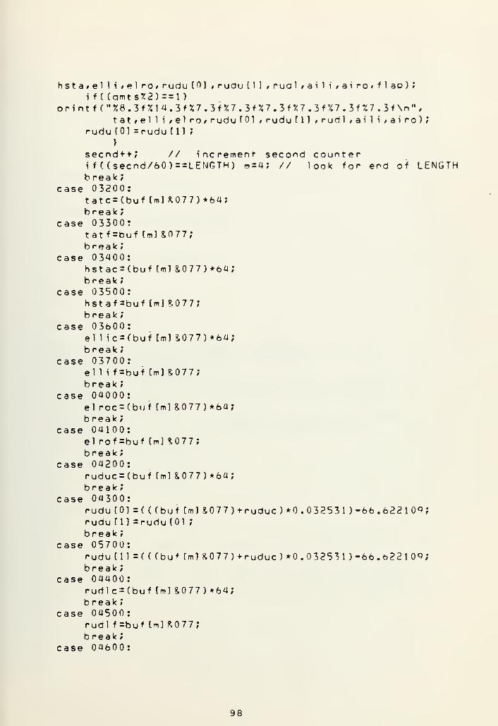
hsta* ell i r e\ po» rudu [0] , rudu [11 rrualfaiH/airo#flap);i f C(gmts%2)==l)
pri nt f( "%8 . 3f XI 4 . 3f %7 . 3f X7 • 3f %7 . 3f %7 . 3f %7 . 3f %7 . 3f \n M
#
tat#elli»e1ro/ruduf0] , rudu T 1 1 > rudl ;ai 1 i >ai ro);rudu f0] =rudu til ;
>
secnd + + ? // increment- second counteri f ( (secnd/60)==LENGTH) m = 4; // look for end of LENGTHbreak
;
case 03200:tatc = (buf (ml *077)*64;break ;
case 03300:tatf =buf tml &077;break ;
case 03400:hstac=(buf[m]&077)*64;break ;
case 03500:hstaf =buf [m] ?, 7 7 ;
break ;
case 03600:el 1 ic=(buf tml &077)*64;break ;
case 03700:el 1 i f=buf (ml &077;break
;
case 0a000:elroc=(buf[m]&077)*64;break
;
case 0^100:el rof=buf Cm] *077;break ;
case 04200:ruduc = (buf [ml&077)*64;break ;
case 04300:rudu [0] =( ( (buf fm] &0 7 7 ) + ruduc ) *0 . 325 3 1 ) -6b . 6 22 1 0<> ',
rudu til =rudu [01 ;
break ;
case 05700:rudu [ll=((Cbuf [ml &0 77 )+ ruduc ) *0 . 3253 1
) -66 . 622 1 06
;
break ;
case 04400:rudlc = (buf [ml &077) *64;b reak ;
case 04500:rudl f=buf [ml R077;break ;
case 04600:
98


ai 1 ic=(buf [ml &077)*64;break ;
case 04700:ai 1 i f=buf [ml *077;break ;
case 05000:ai roc = (buf fml &077)*64;break ;
case 05100:ai rof =buf [ml *077;break ;
case 05200:f lapc = (buf (ml &077)*64;break ;
case 05300:f 1 apf=buf [ml &077;break ;
}
>
)
// SECTION NO. a
f pi =open ( "df dr "
,
) ; // reopen compressed data filesecnd= -1? // initialize second counterwhi le( (secnd/60)<LENGTH) <
read ( f pi , buf , 6) ; // read block of 3 16-bit wordsunpackO? // unpack data into 4 12-bit wordsf or (m = 0;m<4;rn + +) {
oara=bu f [ml &07700 ; // remove parameter octal labelsw i tch (para) { // use label to select casecase 0000:
qmth=buf (ml &077;b reak ;
case 0100:gmtm = buf fml &077;b reak ;
case 0200:gmts = buf [ml &077?
// print headina at beginning of each minute
i f C (secnd%60)==)
<
printf( M \n GMT VHF1 VHF2 TTU1 TR01 TRU2 TRD2");printfC" TRU3 TRD3 SaLl S4L2 S2L1 S2L2 SaRl S4R2\n\n M
);
>
// print data. listing each second
i f (secnd> = 0) {
99


printif ((g
Ps
i f ((gps
if ((gps
if C(gp
s
>
s
i
b
casev
v
b
caset
t
t
t
t
t
b
cases
s
s
s
s
s
b
>
}
}
f (,, *2d:%2d:r,2d%5d%5d",amtH,gmtm,gmts,vhf 1 t vhf2) ;
m ts%4)==0)ri nt f ("*5d%5d%25d%5d%5d #/5d%5d%5d\n" , t rul , t rdl ,
J411,sl412,sl21i,sl212,sl4rl,sl4r2);mts%4)==l )
rintf ("%15d%5d%15d%5d%5d%5dX5d%5d\n" ,tru2,t rd2,?4UrSl4l2rs12U#sl2I2,s14rl#sl4p2);mts%4)==2)rintf (
M %2Sdr.5d%5d^5d ,/i5d^5d% t5d%5d\n" ,tru3,tpd3,14U,sl412,sl2U,s1212,sl4pt,sl4p2);mts%4)==3)rint f (
,, %35dy.5d%5d%5d%5d%5d\n" ,
141 l,s14]2,sl2U*sl212,sl4rl,sJ4r2);
ecnd +
f ((sereak ;
05400hf 1 = (
hf2 = b
reak ;
05500rul = (
rdl = (
ru2=(rd2=(ru3=(Pd3 = b
peak
;
056001411 =
1412 =
121 t =
1212 =
14r2 =
1 4rl =
reak ;
+/ // increment second countercnd/60)==LENGTH) m=4; // look for end of LENGTH
buf [ml &02)>>1 ;
u f t m 1 & 1 ;
buf (m] S040)>>5;buf [ml S020)>>4;buf Cm] &01 0)>>3;buf (ml S04)>>2;buf tm] *02)>>1 ;
uf [ml &01
;
(buf Cm] &040)>>5;(buf (ml &020)>>4;(buf (ml &010)>>3;(buf (ml &04)>>2;(buf (ml &02)>>1 ;
buf [mj S01
;
// UNPACK DATA
unpack ( ) {
buf 131 =buf (21 &07777;buf [21 =( (buf (21 >>12)&017)buf (11 =( (buf (11 >>8U0377)buf(01=(buf(0J>>4)R07777;>
( (buf (11 <<4)*07760);((buf(01<<P)&07400);
100


APPENDIX E
PROGRAM TO PLOT ORIGINAL AND COMPRESSED DATA
A. PLOT DESCRIPTION
This routine was written in FORTRAN and was designed to
plot the data from ORIGIN. C and RECOV.C on the Calcomp plotter.
The program consists of three sections which correspond to the
first three sections of the parameter listing. The fourth
section is not plotted because it contains discrete parameter
data which very seldom changes. The original and recovered
data listings were written onto magnetic tape in IBM compatible
format and used directly as the source of data for the routine.
The parameters are first read from the tape in records
which correspond to the lines in the data listings. The para-
meters are scaled if necessary and stored until all parameters
for the required time interval have been processed.
The parameter values are plotted versus time using the
subroutine DRAWP which generates control data for plotting
graphs on the Calcomp plotter. DRAWP is a simplified version
of the Naval Postgraduate School subroutine DRAW. The argu-
ments required in the subroutine call are; the number of
points defining the curve, an array containing the X-ordinate
(Time) and an array containing the Y-ordinate (Parameter)
.
The final two arguments are arrays used to specify optional
plotting control information such as the number of curves on
a graph, scaling, title, etc.
Plots made using this routine can be seen in Appendix F
and Section IV, Figures 2-4.
101


cC e. FLCT LISTINGCCC THIS FCLTIN6 WILL PLOT THE CATA FPCM ORIGIN.CC ANC FECCV.C CN THE CALCCMP PLCTTEP. THE PROGRAMC CCNSISTS CF THREE SECTIONS WHICH CCRRESFCNC TC THE FIRSTC THREE SECTICNS CF THE PARAMETER LISTING. THE FCUFTHC SECTICN IS NOT PLCTTEO BECAUSE IT CONTAINS DISCRETEC PARAPE7EF CATA.CC IF THE CPIGINAL AND RECCVERED DATA LISTINGS ARE WPITTENC CN MAGNETIC TAPE IN IBM COMPATIBLE FORMAT THEY MAY 65C USEC DIRECTLY AS THE SOURCE OF DATA FOR THIS PRCGFAN.CC
DINENSICN SECNC(72G), ALTF(180), CASdSC)CINENSICN HEAD(180), PITCH(18Q), ROLL(ISO)DIMENSION ENG118C), ENG1<18Q>, ENG2(1S0), ENG3(180)CINEhSICN LCNG(iaO), VERGC720), LATG(720)DIMENSION AILK180), AIR0(180), FLAPdSO), TATU80)DIMENSION HSTA(180), ELLK180), ELRCdSO), RLCK560)CIVENSICN RUCH180), TATU183), HSTAH180), FLAFK18G)IMEGEF*4 I7E(12)/12*0/R£4L*4 RTB(28)/28*C.O/ECLIWLENCE(TITLE,RTB(5) )
REAL*E TITLE(12)CC INITIALIZE X-ORCINATE ARRAYC
CC 2C 1=1,720SECNCd ) = I-1
20 CCNTINLECC SECTICN NC. 1CC 1ST SECCNCC
c
REAC(4,10G) ALTF(l), CAS(l), HEAC(l), PITCH(l),lPCLL(l), ENC-d)ENC-l(l) = ENG(l)-80.0ENG2( 1)=ENG1<1)EfsG2(l)=ENGld )
HEAC(1)=HEAC(1>-183.0AL7F(1)=ALTF(1)-160.0C AS (1)=CAS( D-287.0DC 40 1=2,60PEAC(4,200) ALTF(I), CAS(I), HEAC(I), PITCH(I),
lPCLL(I), ENG(I)ENCKI )=ENG1(I-1)ENG2( I ) = ENG2 ( 1-1)ENG3(I >*ENG3( 1-1)HEA£d)=HEAC(I )-183.QALTF( I)=ALTF(I)-160.0CASd )=CAS( D-287.0IF(I-(I/4)*4.EC.l) ENGld )=ENG(I)-8Q.CIFd-d/4)*4.EC.2l ENG2(I ) = ENGd )-8G.CIFU-(I/4)^.EC.3) ENG3(I ) = ENGd)-80.G
40 CCNTINLECC 2NC SECCNC
PE AC (4,100) ALTF(61 ), CAS (61 ) , HEAD( 6 1
)
f PITCH ( 61
)
1RCLLU1), ENG(61)ENG1U1)=ENG<61)-80.0ENG2U1) = ENG2(60)ENC2Ul) = ENG2(60)HEACU1)=H£AD(£1>-183.0ALTF U1)=ALTF(61)-163.CCASUi)=CAS (6D-287.0CC 50 1=62,120REACH. 2CG) ALTFd), CASd), HEAC(I), FITCH(I),lRCLL(I), ENG(I)
102


5CCcc
55CCccc
60CCC
70Ccc
75Cr
Ccc
EKC-KI )=ENG1(I-1)ENG2(I )=ENG2(I-1)ENG2( I)=ENG2(I-1)H54C(I)=FE£C(I J-183.0AL7F (I)=ALTP(I)-160.0C*S(I)=CAS< D-287.0IF(I-(I/4)*4.EC.l) ENGKIIF(I-(I/4M4.EC2) ENG2UiF(I-(I/4)*4.EC3)CCNTINLE
) = ENG( I )-80.0) = ENG( D-30.0
EMG2(! )=ENG( I )-80.0
3RD SECCNC
PE4C (
1RCLKENGKENG2(ENG2(HE^C(AL7F(CASQDC 55RE4C (
1PCLUENGKENC-2<ENG2(HEAUALTF (
C A S ( I
IF(I-IF(I-IF(I-CCNTI
4,12121212121221
I
4,I)I)I)I )
I)I))=
(I(I(IM
100)l)t1)=E1)=E1)=E1)=H1)=A)=CA= 1222C0), EN= ENG= ENG= ENG= FEA= ALTCAS(/4)*/4)*/4)*E
1) ,CAS(121) , HEAD ( 121 ), PITCH (121),
80.0
ALTFC12ENG(121)NG(121)-NG21120)NG3U20)EAC<121)-1£2.0LTF(121)-160.0S(121)-287.0
'ALTF(I), CAS(I), HEAC(I), PITCH(I),G(I)1(1-2(1-3(1-C(I )
F(I)n-24. EC4. EC4. EC
)
)
11
1)-183-160:87.0.1 )
.2)
.3)
.0•
ENGKI ) = ENG(I)-80,CENG2(I )=ENG< I)-80,CENG2(I )=ENG(I)-8C.C
SEC7ICN NC. 2
1ST SECCNC
RE*C(4,400) LCNG(l), VERG(l), \/ERG(2), VERG(3),1VERG(4), LATG(l), LATG(2), LATG(3), L/STGC4)DC 60 1=2,60J=(I-1)*4REAC(4,500) LONG(I), VERG(J+l)
rVERGU + 2),
1VEPGU + 4), LATG(J+1), LATGU+2), LATGU + 3),CONTINUE
VEPG (J+2),LATC-< J + 4)
LCNG(61) ,
LATG(241)
,
120
LCNG(I)
,
LATGU + 1)
VERG( 241)LATG(242)
VERG( J+l),LATG(J+2)
VERG(242)LATG(242)
V6RG(J+2) t
LATG(J+2)
VEPG(242)LATG(244)
V=RG(J+3) ,
LATG(J+4J
2ND SECCNC
REAC (4,400)1VEPG(244)
,
CC 70 1=62,J=(I-1)*4PEAC (4,500)1VEPGU + 4),CCN7INLE
2RD SECCNC
REAC(4,400)1VEPG(4€4),DC 75 1=122J=(I-1)*4R6*C (4,500)1VEFGU + 4)
,
CCNTINLE
SECTICN NC. 2
1ST SECCNC
P E AC (4,600) hSTA(l)
,
ELL I ( 1 ) , ELRC ( 1 ) , PLDU( 1 ) , PUD I ( 2 ) ,
lRLCL(l), AILK1), AIRC(l), FLAP(l)
LQNG(121)LATG(481 ),,180
LGNGd ),IATGU + 1) ,
, VERG(481), VERG(482), VEFG(482)LATG(432), LATG(482), LATG(484)
VERG( J+l)
,
LATGU+2)VERGCJ+2), VEPG(J+2) ?LATGU + 2), L*TG(J+4)
103


60Ccc
90CCc
c c
ico2CC200ACQ5006C0700Cr
ccc
TATK l)=-4.487CC 80 1=2,60JMI-1)*2»EAC (4,700) TAT(I)»HSTA(I I.ELLKIlilRLCU(J+2)f FUCLd), AILKI), AIROdTMim»TATK 1-1)HS7AKI ) = FS7AKI-1)FL*P1(I) = FLAPKI-1)IFd-(I/2)*2.EC.O)IF(I-(I/2)*2.EC.O)IF(I-d/2)*2.EC.l)CCMIME
2ND SECCNC
ELRCd ),RUCU(J+1)), FLAP(I)
TATKI )=TAT(I)+9.GFLAFKI )=FLAF(I )
HSTAKI )=HSTA(I )
RE AC (4,600) HSTA(61),ELLI(61) ,ELRC(61) ,RUDU(121 ),, AILK61), AIR0(61), FLAP(61)1RLCU(122), PU0K61)
TAT1(61)=TAT1(60)CC 90 1 = 62, 120J = d-1)*2RE*C(4,7C0) TA7(I),1RLCUU + 2), PUDL(I),TA71 ( I )=TAT 1( 1-1
)
HSTA1(I)=HS7A1(I-1)FLAP1(I)=FLAP1(I-1)IF(I-(I/2I*2.EC,0)IF(I-(I/2)*2.EC.O)IF(I-d/2)*2.EC.l)CONTINUE
3RC SECCNC
HSTA(I ),ELLI (!) 2 ELRCd ), RUCK J + l)AILId ) , AIROd ) , FLAP( I )
TATKI)=TAT(I)+9.CFLAPKI )=FLAFd )
HSTM(I)=»-STA(I )
HSTAd ),ELLI (I )
AILKI), AIRC(,ELPC(I), RUCU (J + l) ,
I), FLAP(I)
PE*C( 4,600) HST A (121), ELL I (121) ,ELRC(121) .RUCL (241),1PLCU(242), RUDL(121), AILK121), AIPC(121), FLAFC121)TM1(121)=TAT1(120)CC 95 1=122,180J=(I-1)*2REAC(4,700) TATd),1PUCUU + 2), PUDL(I),TA71(I)=TAT1(I-1)HS7A1(I)=FSTA1(I-1)FL4FKI )=FLAFKI-1)IF(I-(I/2)*2.5C.O)IF(I-(I/2)*2.EC0)IF(I-(I/2)*2.EC.l)CCNTINLEFCPMAT(///15X,F6.0,F8,2,F8.2,F9.3,F9 B 2,F21o2)FCFMdT(15X,F6.0,F8.2,F8.2,F9.3,F9.2,F21.2)FCFYATUA8)FCFMA7(///8*,9F8.4)FCFMA7(8X,9F8.4)FCFMA7(///8X,F15.3,8F7o3)FCFN/ST(8X,F6.3,9F7 a 3)
TATKI )=TAT(I) + 9.0FLAPKI )=FLAP(I )
HSTAKI )=HSTA(I )
THE FARAfETER VALUES ARE PLOTTED USINGCRAfcF WFICh GENERATES CCNTRQL DATATHE CALCCMP FLCTTER
ITE(3)=9ITE(12)=1R7E(2)=20.0REAC(5,3C0) TITLECALL CPAWP(180,S£CN0,ALTF,ITB,RTBJRTE(2)=2a0PEAC(5,300) TITLEC*LL CPAWP( 180,SECMD,CAS, ITB,RTB)P7E(2)=1.0REAC ( 5,30C) TITLEC*LL CRAWP( 180,S5 CMD,FEAD, I TB,RTB)R7E(2)=C5REAC(5,300) TITLEC4LL CPAWP( 180,SECND,PITCF,IT3,RTB)RTE(2)=1.0
THE 5USRCL7INS
104


REACcallR7E(REACC4LLR7E(REACC*LLR7t(REACC*LLPEACCALLI7E(R7E(R7E(RE*CCALLREACC4LLITE (
R7£(REACCALLR7E(RE£CCALLR7E(PEACCALLR7E(READCALLR7E(REACCALLP7E(REACC4LLR7E(READCALLS7CPENC
(5,200)CPAWP(
2)=5.0(5, 200)CRAhP(
2)=5.0(5,200)CRAWP(1 = 5.0C ,2CC)
2(
CPAWP((5,200)CRAWP(
8) = 1
2)=C.Qi)=eo.o(5,200)CRAWPt(5,200)CRAWP(
8)=C2)«1.0(5,200)CRAWPt
2)=0.5(5,20C)CRAWP(
2)=0.2(5,2C0)CPAWP(
2)=0.5(5,200)CPAWP(
2)=0.5(5,200)CRAWPt
2)=2.0(5,200)CRAWPt
2)=C.C5(5,200)CRAWPt
7I7LE180,SECND,RCLL,I7e,R7E)
TI7LE180,SECND,ENG1,I73,R7B)
7I7LE180,SECNC,ENG2,I7B,R78)
7I7LE180,SECNC,ENG3,I7B,R7E)7I7LE180,SECND,LCNG,I7B,R78)
7I7L5"i20,SECND,VEPG,I7B,R7B)7I7LE72C,SECND,LA7G ,I7B,R76)
7I7LE180,SECND,7A71,I7B,R7E)
7I7LE180,SECNC,ELLI ,I7B,R7B)
7I7LE180,SECN0,ELRO,I7B,R7B)
7I7LE2 60,SECND,R0CU,I7B,R7B)
TI7LE180,SECj\D,RUCL,I7B,R7e)
7I7LE180,SECND, AILI ,I7B,R7E)
7I7LE180,SECND,AIRC,I7B,R7e)
105


APPENDIX F
FLIGHT PARAMETER LISTINGS AND PLOTS
This appendix contains examples of listings and plots
produced by the programs ORIGIN. C, RECOV.C and PLOT. The
plots contain three minutes of data which includes the first
minute of turbulence. The original and restored parameters;
Fine Altitude, Computed Air Speed, Roll Attitude, Engine #1
Thrust and Vertical Acceleration are plotted. The recovered
data plot of each parameter is followed by its original data
plot for easy comparison.
The listed data corresponds to the last minute of data
in the plots. The four sections of recovered data are fol-
lowed by the corresponding four sections of original data.
106


4J
4J
<u
0)
Ixi
okQ
rH
T3
13
Xi <ucH A\ oCO CT3 HC \
-Po cu
CD cu
(SI Cm
o OCM CN
CD <D
<o to
UCO C/2
1 I
X ><
QW«
>ooa
wQDEh
HEn
QT- SCC gcc 2CC
107

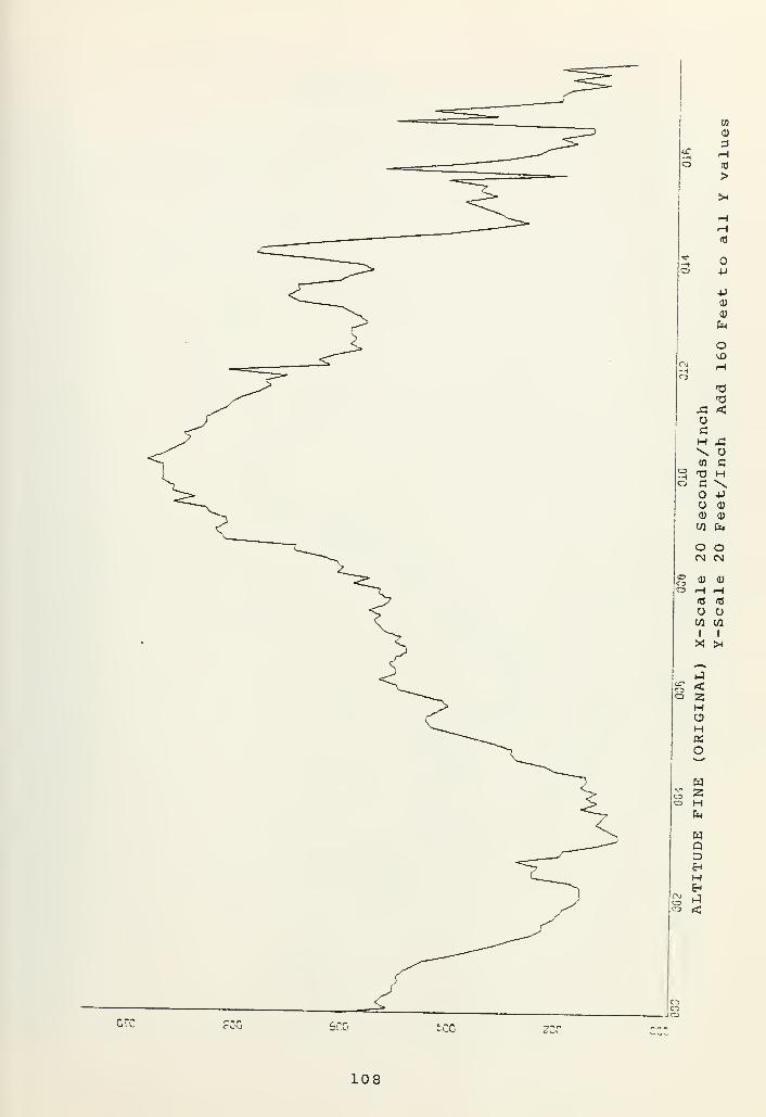
108

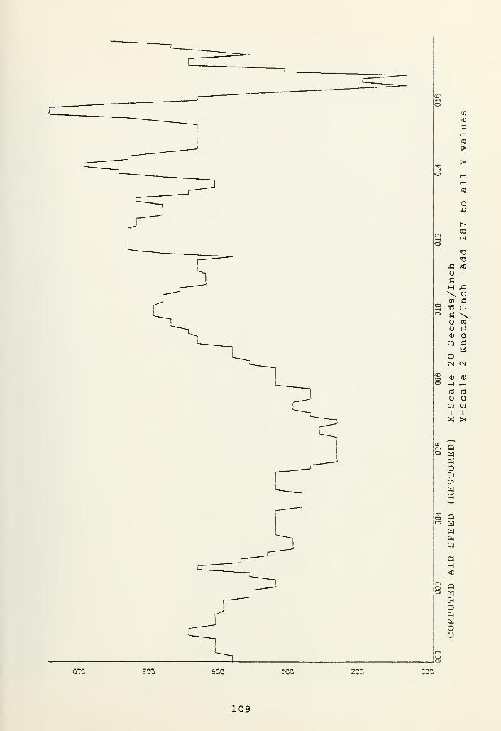
GTC ?00 500 XG
109


err 5CG tec
110


43o-H\W J3T3 oC aH
o \<D CPCO 0)
aoCN rH
(U (U
r-i fH(0 <C
O Oen ai
X :*
J#—
QHOS
W>ouwa;'—
wQDEn
HEh
Eh
«:
JJOoi
ZCG-
111


112


JC oO 00cH T3
\ T3CO <-aCO J3O Od) cCO H
O <*>
cn in
Q) 0)
lH r-i
oCO CO
1 I
Qwa:
w>ouwa;
En
CO
DOS
E-«
sHe?
S2C :2G OTQ ?CD CGQ
113


114


c
u>Tz
USo
OAa -aH <\CO
C UC
O HCD \CO C7>
o •
(N Oo CD 0)
rH iHnj as
OCO CO
1 I
Qm
>ouwa:
2OHEh
<$
w
wou
uHEh
I*
W>
•:-r:G r^u :co
115


116


GMT
2 1 :ai : o
2 :4i : i
2 :ai : 2
2\ :<t\: 3
21 :ai : a
21 : a i : 5
21 :ai : &
21 :«1 : 7
21 : a 1 : 8
21 :ui : o
21 : a 1 : 1
21 :ai : i i
21 :ui : 1221 :ai : 1321 :ai : ia21 : a l : i 5
21 :ai : 1621 : a i : i 7
21 : a i : 1
8
21 :«1 : 1Q
21 :ai :2021 :«l :2t21 :4i :2221 :4l :2321 : 'i 1 : 2 a
21 :ai :2521 :«1 :2b21 : a l : 2 7
21 :4i :2821 :41 :2921 :ai :3021 :ai :3121 :ai :3221 :ai :3321 :ai :3a21 :ai : 3521 :4i :3621 • a i : 3721 •«1 :3821 ui :3921 ui :uo21 41:4121. 41:4221 : 41:4321 : -il : a u
21: 41 :a521 : 41 :4621: 41 :4721: 4] :4821 : 41 :4921 : 41 :5021: 41:5121: 41 :5221: 41 :5321: 4 1 :5421: 41 :5521
:
41 :5621: 41 :5721: 41 :5821 : 41 :59
ALTC
32768
32768
32768
32768
32768
327b8
32768
327e8
327o8
32768
32768
32768
32768
32768
327o8
4LTF CAS *E 4I3 PITCH ROLL N1ENG1 N1ENG2 MENG3
05.25
233 205.75 187.38 1 .758 0.0244 205.75 187.38 1 .406 0.00225 295.75 187.38 1 .406 -0.70225 295.75 187.03 1 .406 -0.70225 295.75 187.03 1 .406 0.0219 205.75 18 7.03 1 .406 0.0219 295.50 18h. 08 1 .406 -0. 35210 295.50 18<j.o8 1.406 -0.35221 295.50 186. 08 1 .406 -0.35221 29a. 75 I80.08 1 .406 -0.70221 29a. 75 180.68 1 .406 -0.70219 29U.75 18b. &8 1 .055 -1.05219 294.75
1 8b.b8 1 .055 -1 .05223 295.50 186.68 1 .055 -0. 7023t 295.50 1 3b.b8 1 .055 -".70231 2oa,00 18b. 33 t .055 -0.35231 204 . nO 18b. 33 1 .055 -1 .05231 293.25 18ft. 33 1 .055 -1 .05223 293.25 186.68 1 .055 -1.05223 293.25 l*6.o8 1 .055 -0.35217 204.75 1 8b. 08 1 .055 -0.35217 296.00 185. o* 1 .055 -0. 35228 29b. 00 I8S.09 1 .055 -0.35239 29 7.0 185.98 1 .055 -0.70239 207.00 186.33 1 .055 -0.70228 205.75 186.33 1 .055 -0.70216 295.75 186.33 1.406 -0. 70203 29'4.75 186.33 1 .4 06 -0.701^5 203.75 186.33 1 .40b -0.7188 2Q3.75 18b. 33 1 .40o -0.701^2 293.75 186.33 I .40b -0. 70'
1^2 293.75 18b. 33 1 .406 -0.701°7 203.75 186.33 1 .40b -0.70107 293.75 186.33 1 .0^5 -0. 701^7 203.75 1"6. 3 3 1 . 4 -0.71«7 203.75 1 8b. 08 1 .055 0.7107 294.75 lHb.68 1 .055 0. 7020 3 295.75 185.63 0.703 -0. 35IM 208.00 1«5.63 1 .055 -1 .05215 2OH.00 185.63 1 .055 . u2C1 298.00 185. b3 1.055 -1.0510? 206.25 185.63 0.703 -2.'Jn186 203.75 185.98 1 .406 -0.35186 293.75 185.27 1 .40b . 701 70 202.00 18a. 57 1.406 0. 70170 2«Q.75 18a. 57 1.40b -0. 3517Q 287.75 1*4.57 1 .055 -1.40170 280.00 184.5 7 1 .406 0.35213 280.00 183.52 0.70 3 0.3519a 287.75 183.52 1 .055 -2. 4620& 291.25 183.52 1 .055 -3.87103 201.25 184.57 1 .406 -2. 1 1
182 294.00 184.57 t .055 -1.05132 204.00 184.57 1 .055 -1 .05182 2oa. 00 184.22 1 .055 -2. 1 1
173 202.25 184.22 1 .055 -1.05180 203.25 184.57 t .055 -1.05173 294.50 184.57 1 .406 0.35182 2oa. SO 184.57 1 .055 2. 4b168 296.25 184.57 1 .055 -0.7
06.65
94.70
93.42
93.32
93.08
93. 08
00.85
88 .99
80.23
80.78
«3.oq
81 .27
04.12
97. o9
95.80
93.20
92.32
92.26
02.04
91 .95
88. 47
87. b2
87.68
87.77
81.03
80.63
93.75
95.70
94.03
96.01
94.15
93.54
93.45
03.35
03. 08
8.9.2 3
88.99
89.08
89. 17
81.18
36.46
97.29
97.1 1
9a. 58
SECTION NO RECOVERED DATA
117


GMT LONG VERG VE»G VFPG VERG LATG LATG LATG LATG
41 : 0.0423 0.9549 0.O824 1 .0373 1 .0373 0.0174 0.0174 0.0052 0.017441 : 1 0.0397 1 .0007 1.0007 1.0007 1 .0282 0.0174 -0.0070 0.0011 0.0072ai : 2 0.0347 1.0098 1 .0098 I .0190 0.9Q15 0.0072 0.0 194 0.0235 0.023541 : 3 0.0403 1 .0282 1 .0282 1 ,04b5 t .04b5 0.033b 0.033b 0.0255 0.021441 : 4 0.0382 1 .0098 1 .0008 1 .0OQ8 1 .0098 0.0214 0.0174 0.0113 0.01 13
41 : 5 0.0352 1 .0007 1 .0007 1 .0190 1 .0007 0.0113 0.0113 0.0133 0.013341 : 6 0.0352 1 .0007 1 .0007 1 .0007 0.9015 0.0133 0.0133 0.0133 0.0113
:ui 7 0.0336 O.9015 0.9915 0.9915 O.oo 15 0.0113 0.01 13 0.01 13 0.011341 : 8 0.0336 0.9915 0.9QJ5 0.9915 1 .0007 0.0113 0.0113 0.0113 0.011341 : 9 0.033b 1 .0007 1 .0007 1 .0007 1 .0007 0.0113 0.0113 0.0113 0.01 13
41 : 10 0.0336 1 .0007 1 .0007 1 .0098 1 .0098 0.0113 0.0133 0.0133 0.017441 : t t 0.033o 1 .0098 I .0 098 1 .0008 1 .0007 0.0174 0.0174 0.01 13 0.011341 :12 0.033b 1 .0007 .OH24 .9824 0.9824 0.0113 0.0113 0.0174 0.01744 l :13 0.031b 0.9824 .9540 0.9549 0.9549 0.0174 0.0214 0.0214 0.017441 : 14 0.031b 0.954O 0.°3oo 0.936O .93bb 0.0174 0.0133 0.0072 0.00724 1 :15 0.0316 0.936O 0.93hb 0.9366 0.936b 0.001 1 0.0011 0.0011 0.003141 :16 0.03tb U.9r>41 0.9 41 O.9015 0.9915 0.0 092 0.0092 0.0113 0.01134 1 : 17 0.0341 0.9O15 O.0015 0.99J5 1 .0098 0.0113 0.0153 0.0214 0.02144 1 :18 0.0341 1 .0098 1 .0190 1 .0100 1 .0190 0.0235 0.0194 0.0255 0.02144 1 :l<> 0.0341 1 .0190 1.0373 1 .0373 1 .0373 0.0214 0.0214 0.0194 0.019441 :20 0.0341 1 .0373 t .0 373 1 .0373 t .0 190 0.0113 O.0113 0.0113 0.011341 :2I 0.0301 1 .0098 1 .0098 0.9915 0.9915 0.0113 0.0113 0.0072 0.00724 1 :22 0.02b0 0.9641 0.9b41 0.O64 I 0.9641 0.0072 0.0072 0.0092 0.009241 :23 0.0235 0.94158 0.9458 .0458 0.9274 0.0092 0.0113 0.0113 0.01134 1 :2« 0.0219 0.9274 0.9274 0.Q458 0.9458 0.0153 0.0153 0.0153 0.01534 1 :25 0.0219 0.9641 0.9b4l 0.9824 .9824 0.0133 0.0133 0.0133 0.013341 :26 0.0255 0.9824 1 . (M)O 8 I .0 190 1 .0190 0.0 133 0.0133 0.0133 0.00924 1 :27 0.0275 1 .04 O 5 1 .0465 1 .0648 1 .0b48. 0.0 92 0.0133 0.0133 0.013341 :2B 0.0275 1 .0b48 1 .04o5 1 .0465 1 .04 O 5 0.0 174 0.0174 0.0174 0.01744 1 :29 0.0275 1 .04b5 1 .04b5 1 .0282 1 .0098 0.0133 0.0133 0.0133 0.013341 :30 0.0255 .9824 1 .0373 1.0373 I .0098 0.0133 0.0133 0.0072 0.00724 1 :31 0.0I1" 1 .0 008 0.O732 0.9732 0.9732 . 7 2 0.0174 0.0174 0.01744 1 :32 0.0250 0.9549 O.0540 0.99 15 0.9915 0.00O2 0.0092 0.0092 0.00524 1 :33 0.0219 0.9O15 n .9540 0.954O 0.9274 0.0052 0.0113 0.01O4 0.023541 :34 0.0219 0.9274 0.o?74 0.9274 1 .055o 0.0235 0.0214 0.029b 0.029641 :35 0.0357 1 .2662 I . I5b3 1.0007 0.9183 .0490 0.0581 0.0418 0.02554 t :36 0.0270 0.9b41 1 . 1 1H5 1 .1563 1
.
I5b3 0.0113 -0.0030 0.0031 -0.01934 1 :37 0.0138 1 .0022 0.Q824 0.8*17 0.8817 0.0031 0.0113 0.0255 0.025541 :38 0.01 74 0.O732
1 .0373 1 .0008 0.8725 0.0357 0.0153 0.0153 0.02554 1 :3<J 0.00b2 0.7o27 0.9274 0.9824 0.9274 -0.0152 0.0275 -0.0091 -0.02544 1 :40 0.0062 1.0007 1 . 1 105 1.0373 0.8O08 -0.009 1 -0.0091 0.0214 0.003141 :4i 0.0092 .OhU l I .24 79 1.1014 .8634 0.029 O 0.029b 0.0804 0.07234 1 :42 0.004b 0.db34 ,8h34 0.7718 .9000 0.0540 0.0174 0.0052 0.037741 :43 0.0250 1 .0022 1 . 1338 I .0831 0.9824 0.0092 0.0092 0.0235 0.003141 : aa 0.0143 0.8817 0.8634 1.0007 1 .0373 0.0031 .0092 -0.0172 -0.017241 :45 0.0214 0.O732 I .0098 1 .0648 I .0b48 -0.0111 0.0011 -0.0070 0.02144 1 :46 0.0291 1 .0648 0.O36O 0.936b 0.817b 0.029b 0.0581 0.0581 0.064241 :47 .0408 0.9OUO 1 .0190 1 .0190 1 .055b 0.090b 0.0235 0.0174 -0.013241 :48 0.0387 1 .055b 1 .055o 0.9732 0.7443 -0.0132 -0.0132 -0.0376 -0.031541 :a9 0.0408 0.8542 0.8725 0.9641 1 .0465 -0.0315 -0.0498 -0.0355 -0.0254
: 4 i :50 0.0525 1.1014 1 .2021 1 .0190 0.8817 0.0133 0.031b 0.0174 0.0174:4i :51 0.0418 0.8817 0.93b6 1 .0648 I .1 105 0.0174 0.0235 0.0357 0.0357:4i :52 0.0458 1 .0648 1 .0648 1 .0373 I .0007 0.0397 0.0214 0.0133 -0.0070: J 1 :53 0.0a28 0.9458 0.9732 1 .0739 1.10 14 0.0011 -0.0152 -0.0030 -0.0091:4i :54 . 0448 1.10 14 1 .055o I .0556 1 .0007 0.0031 0.0255 0.0194 0.0194:4i :55 0.0418 1 .0007 1 .0373 1 .0007 1.0373 0.033b 0.0113 0.0113 0.0031: 4
1
:5b 0.031b 0.9732 1 .0465 0.9366 0.9091 0.0031 -0.0050 -0.0233 0.0133:4i :57 0.0397 0.9091 0.90O1
1 .2021 1 . ! 746 0.0296 0.0479 0.0601 0.0296i
: 41 :58 0.0357 .03fae, 1 .0190 . 00 1 5 1 .0190 -0.0030 0.U377 0.0052 -0.0152i : 4] :59 0.0214 1 .0922 1 . Ib55 1.10 14 0.9091 -O.0274 -0.0091 0.0072 0.0520
SECTION NO RECOVERED DATA
118


GMT TAT nSMb ELEVLI ELEvRO R'tDUP RUDUP RUDLO A ILL I AILRO FLAPR3
41 : .402 -0.418 0.450 1 .042 1 .042 .652 2.372 -0. 199 0.00141 : I -13 .487 0.290 0.300 0.652 0.652 . 164 1 .124 -0
. 199
41 : 2 .402 0.290 0.450 0.001 0.001 -0 .259 -0.249 -0, 199 0.001
4] : 3 -12 .987 0.290 0.450 0.001 0.522 -0 .389 1 .124 -0, 199
41 : 4 .402 0.290 0.450 0.^22 0.522 ,099 1.997 -0 199 o.oot4] : 5 -12 .987 0.290 0.450 0.522 0.522 ,0 99 0.749 -0
. 19941 : 6 I .402 0.007 0.450 0.132 0.132 -0
. 194 0.749 -0 . 199 0.00141 : 7 -12 .987 0.007 0.450 0.132 0.132 -0 . 194 0.749 -0 19941 : 9 .402 0.007 0.450 0.132 0.1 32 -0 .356 0.749 -0
. 199 0.00141 : 9 -12 .987 0. 14A 0.450 0. 132 0.132 -0 .356 0.749 -0
. 1994 I : 10 L .402 0.148 0.450 0.132 0. 132 -0 .356 0.375 -0
, 199 0.00141 : 1
1
-12 .488 0.148 0.450 0.132 0. 1 32 -0 .35o 0.375 -0. 199
41 :12 .402 0. 148 0.U50 0.262 0.262 -0 , 194 0.749 -0 . 199 0.0014 1 : 13 -12 ,488 -0.2 77 0.450 0.2o2 0.2b2 -0
. 1 °4 0. 749 -0. 199
4 1 : 14 .402 -0.277 0.300 0.262 0.392 .00 1 1 .373 -0 199 0.0014 1 :15 -12 .488 0. 148 0. 300 0.392 0.001 -0
, 129 1 .373 -0. 1994 1 : lb .a02 0.148 0.300 0.001 0.001 -0 519 -0.125 -0, 199 0.0014 1 :17 -12 48« 0.573 0.300 0.001 0.001 -0 .519 -0.125 -0 1994 1 :18 .4 02 0.573 0.300 0.262 0.262 -0 .226 0.874 -0. 199 0.00141 :l« -12. U8« 0.573 0.450 0.522 0.522 o ,00 1 1 .373 -0, 19941 :20 .402 0.290 . 6 o 0.522 0.522 .00 1 1.373 -0. 199 o.ooi41 :2l -12 488 -0.1 35 0.450 0.262 0.2b2 -0 ,064 0.500 -0
. 1994 1 '.22 .402 -0.560 0.450 0.001 0.001 -0 ,35b 0.500 -0. , 199 0.0014 1 :23 -12 .488 -0.560 0. ISO 0.001 0.001 -0 ,487 0.500 -0 .19941 :24 .402 0.007 0.300 0.001 0.262 -0 ,487 0.99Q -0
, 199 o.oot4 1 :25 -1 1 .988 0.431 0.300 0.262 0.2b2 -0 .226 .999 -0
, 1994 1 :26 .402 0.431 0.450 0.262 0.2b2 -0 .226 .999 -0
. 199 0.00141 '.27 -t 1 .988 0.856 0.450 0.262 0.262 -n .22* 0.250 -0
. 19941 :28 I .402 0.856 0.450 0.132 0.1 32 -0 ,22o 0.250 -0
. 199 0.00141 :2<> -1 I ,988 0.431 .600 0.132 0.262 -0 .226 0.874 -0 . 19941 :30 1.402 0.007 0.600 0.262 0.262 -0 .226 0.874 -0 . 199 0.0014 1 :31 -1 1 .988 0.007 0.450 0.262 0.262 -0 .226 0.250 -0
, 1994 1 :32 I .402 0.007 0.450 0.132 0.1 32 -0 .22o 0.250 -0
, 199 0.0014 1 :33 -12 .488 0.007 0.450 0. 132 0.132 -0 .356 0.o24 -0 19941 :34 .402 0.007 0.450 0.132 0. 1 32 -o .356 0.o24 -0 199 0.0014 1 :35 -12 ,488 1 .98° 0.300 0.b52 1 .433 .00 1 3.371 -0 .23841 :36 1.402 0.007 0.750 1 .433 0.522 .
3 45 1 .498 -0, 199 0.001
4 1 :37 -12 .488 1 .281 0.450 0.001 0.001 -0. 161 -0.125 -0
, 1994 1 :38 1 .402 -0.985 0.300 0.001 0.2o2 -0 .389 -0. 125 -0
,199 0.001
4 1 :39 -12 .488 -0.4 18 . 0.262 0.262 o .00 1 2.122 -0. 159
4 1 :40 1 .402 0.573 0. 150 -0.5 19 -0.5 19 -0 .844 -0.499 -0 159 0.0014 1 :4i -10 .989 0.998 0.300 -0.5 19 0. 1 32 -0 .844 -2.74b -0 ,27H4 1 ••42- .402 -0.1 35 0.600 1 . 1 72 1.172 .359 1 .873 -0 199 0.0014 1 :43 -10 .989 0.856 0. 150 1 .172 0.o52 .880 2.622 -0 1994 1 : 44 1.402 0.431 .oOO 0.o52 0.262 .229 1 .^73 -0 199 0.001
:4
1
:45 -10 .989 0.431 .450 -0.389 -0.3*9 -0 .552 -0.374 -0 1994 1 :4b 1 .402 1 .281 0.450 -^.38° 0.392 -1
. 170 -0.374 -0, 199 0.00141 :47 -1
1
.489 -0.418 0.600 1 .693 1 .693 .359 3.371 -0. 199
41 :48 1.402 1 .848 0.300 0.652 -0.259 .782 0.000 -0 ,199 0.001:4
1
:49 -1
1
,489 -0.985 0.750 -1 .040 -1 .820 -1 .137 -3.495 -0 .159:4 l :50 1.402 1 .989 0.000 -1 .820 -0.519 -2 .536 -2.621 -0 .278 0.001: 4
1
:51 -1
1
.489 -0 .418 0.750 0.001 0.001 -0 .552 0.749 -0 199: 4 i :52 1 .402 1 . 140 0. 150 0.652 0.652 o .001 0.749 -0. , 199 0.001: 4
1
:53 -1
1
.489 0. 148 O.cOO O.o52 0.001 . 197 0.250 -0.199
: 4 i :54 1 .402 0.856 . b -0.389 0.001 -0 .747 -2.247 -0 199 0.001:4t :55 -10 .989 0.*5b 0.450 0.001 0.392 -0 .389 0.624 -0 190: 4 t :56 1 .402 0.290 0.600 0.392 0.001 ,00 1 0.000 -0. 199 0.001:4i :57 -10 .984 -0.843 0.450 . 1 1 .042 -0 .617 2.122 -0. 1 19:4
1
:58 I .402 1 .281 0.300 1 .042 1 .042 o . 782 4 .993 -0. 199 0.001: 4
1
:59 -10 .989 0.290 0.750 0.001 -0.779. 132 -3.245 -o
.
238
SECTION NO. 3 RECOVERED DATA
119


GMT VHF1 VHF2 1TU1 TWO J TRU2 TRD2 TRU3 rwr>3 3UL1 S412 32L1 S2L2 S4R1 S4R2
1
2
3
a
5
6 V
7
8
9
10
1 1
12
13la15
IB17
18
19
2021
12 f)
23 1)
2«2S2b27282«3031
32333a
35 I)
36373839aoai 1)
u24344 1)
454b4748 1)
495051525354555b57 1)
5859
1 1
1 t
1 1
1 1
1 1
1 1
1 1
t 1
1 1
1 1
1 1
1 1
1 1
1 t
1 1
1 1 I o
1 I 1
1 L I
1 1 I o
1 I o
1 I L
1 1) I t o
1 L ]I o
I 1 [
1 1
1 1 1
1 1 ]
1 1 ]
I 1 ]
I 1 ]
t 1 1
1 j ]
1 1 ]
1 ] I o1
1 1 [ o
1 L ]
1
1 L
I I [
I L I o
1 I
1 I u I
\ I L
1 L
I nI 1
t 1 t o
1
1 1
1 1 1
1 1
1 1 1
1 1
1 1 ]
\ 1
1 1 1
1 'J
i •J
1 IJ u
1•
'
'J
i''
I
1 II 1 I
1 ij o
1 I
1 1
1
1 [ i o
I I ] I o
1 Q i 1
'
; j 1
>
1 1
1 1
1
!
c 1
!
SECTION NO RECOVERED DATA
120


GMT
:«]
n;
a
a
; U
:u:
a
!«]
: U'
4
a
'
a:
(i
«
:
a
a:
a
a:
:U
a
:4j
;*»!
!«!
:«:
ri:
a
a:
;t'.
a
a
a
a
:41
a
'
a
a
a:
:<J!
:4
:
a
'
:a;
a'
«:
a
!
4'
a
!l!
a
!
a
:«:
a
au
4'
«:
u
a
4
'
ALTC ALTF CAS HEAD PITCH ROLL N1ENG1 N1ENG2 N1ENG3
32768 233 296.00 187.38 .758 0.00 96.681 24a 295.75 187.03 .406 0.00 95.252 225 295.25 187.03 .406 -0.70 96.013 227 205.50 187.03 I .406 -0.70a 32768 224 295.50 187.03 .406 0.00 9a. 70
5 219 295.75 186.68 1 I .406 0.00 03.296 221 295.50 186.68 .406 -0.35 94.157 220 295.25 18o.b8 .406 -0.358 32768 221 295.00 186.68 .406 -0.70 93.429 221 294.75 186.68 .406 -0.70 92.32
10 218 2Q4.75 186.68 .406 -1.05 93.541 1 219 294.75 186.68 .055 -1 .0512 32768 221 295.00 1 86.68 .055 -0.70 93.3213 223 2Q5. 50 18b. 68 .055 -0.70 92.26la 231 294.75 186.33 .055 -0.35 93.4515 233 294.00 18b. 33 .055 -0.3516 32768 231 293.25 186.33 .055 -I .05 93.0817 231 203-.25 186.68 .055 -1 .05 92.0418 225 203.50 18b. 68 .055 -1 .05 93.3519 221 203.75 186.68 .055 -0.3520 32768 217 204.75 186.33 .055 -0.35 93. 1 1
21 219 20b. 00 185.98 .055 -0.35 91.9522 228 296.75 185.98 .055 -0.70 93.0823 239 297.00 186.33 .055 -0.7024 32768 238 296.50 18b. 33 .055 -0.70 90.8525 228 2°5.75 186.33 .055 -0.35 88.4726 216 295.50 186.33 .406 -0.7 89.2327 203 294.75 186.33 1 .406 -0.7028 32768 195 293.75 186.33 1 .406 -1 .05 38 .9929 188 293.50 180.33 I .406 -0.70 87.6230 192 293.25 186.33 .406 -0.70 88.9931 194 294.25 136.33 1 .406 -0.7032 32768 197 294.00 186.33 1 .406 -0.70 89.2333 200 293.75 1«6.33 .055 -0.70 87.683a 194 293.75 186.68 .40o -0.70 89.0835 197 293.25 1 86.68 .055 0.7036 32768 19b 294.75 186.33 I .055 0.70 89.7837 203 295.75 185.63 ().703 -0.35 87.7738 181 298.00 185.08 1.055 -1 .05 89. 17
39 215 208.75 135.63 .055 0.00ao 32768 201 297.25 185.63 I .055 -1 .05 83.90al 192 2o .25 185.63 (^.703 -2.46 81 .0342 186 '293.75 185.08 1 .406 -0.35 81.18u3 184 293.25 135.27 .4 06 0.74U 32768 179 292.00 184.57 .406 0.70 81.27a5 182 289.75 184.22 1 .406 -0.35 80.6346 176 287.75 184.57 1.055 -1 .40 86.4647 176 28O.00 184.57 .406 0.3548 32768 213 280.00 183.52 ().703 0.00 94.1249 194 287.75 183.16 .055 -2.4b 93.7550 206 291.25 183.87 1 .055 -3.87 97.2951 193 201.25 184.57 1 .406 -2. 1 1
52 32768 182 294.0 184.57 1 .055 -1 .05 97.(5953 182 20a. 25 184.22 1 .055 -0. 70 95.7054 180 203.50 184.22 1 .055 -2.11 97.1 1
55 173 202.25 184.57 1 .055 -t .0556 32768 180 293.25 18a. 57 1 .055 -0.70 05. 8057 173 294.50 184.57 1 .40 6 0.35 94.0 358 182 29U.75 184.57 1 .055 2.46 94.5859 168 296.25 184.22 ] .055 -0.70
SECTION NO. 1 ORIGINAL DATA
121


GMT LONG VERG VEWG VERG VERG LATG LATG LATG LATG
41 : 0.0423 0.9U58 0.9824 1 .0373 1 .0556 0.0174 0.0214 0.0052 0.01744 1 : I 0.0397 1.0007 1 .0098 1 .0007 1 .0282 0.0133 -0.0070 0.0011 0.007241 : 2 0.0347 1 .0098 0.9915 1 .0190 0.9915 0.0052 0.019a 0.0235 0.023541 : 3 0.0403 1 .0282 1 .0373 1 .0465 1 .0373 0.0336 0.0296 0.0255 0.021441 : 4 0.0382 I .0098 1 .0098 1 .0007 1 .0007 0.017a 0.0174 0.0113 0.015341 : 5 0.0352 1 .0007 1 .0098 1 .0190 1 .0007 0.01 13 0.0113 0.0133 0.013341 : 6 0.0336 0.9915 0.Q915 1 .0007 0.9915 0.0113 0.0133 0.0113 0.011341 : 7 0.0336 0.9915 C.9915 0.99J5 0.9915 0.0092 0.0133 0.0092 0.011341 : a 0.0336 I .0007 0.99J5 1 .0007 1 .0007 0.0133 0.0113 0.0113 0.011341 : 9 0.033O 1 .0007 1 .0007 I .0007 1 .0007 0.0113 0.0092 0.0113 0.01534 1 : 10 0.0341 I .0098 1 .0098 1 .0098 1 . 0098 0.0133 0.0133 0.0153 0.01744 1 : 1
1
0.0331 1 .0098 1 .0007 1 .0007 1.0007 0.017a 0.0 133 0.01 13 0.011341 : 12 0.0321 0.9Q15 0.9824 0.9824 0.9732 0.0092 0.0153 . 1 7 a 0.02144 1 : 13 0.0316 0.9732 0.9549 0.9549 .°549 0.0174 0.0214 0.0 17a 0.017a4 1 : 14 0.0316 0.9458 0.936O .9360 0.9366 0.0133 0.0133 0.0072 0.00724 ! :15 0.0306 0.9274 0.936o 0.945* 0.9458 0.0011 0.0031 0.0031 0.003141 : 16 0.032o U.9641 0.9732 0.O915 0.9915 0.0092 0.0133 0.0113 0.011341 :17 0.0341 0.9915 0.9915 1 .0007 1 .0098 0.0133 0.0153 0.02U 0.021441 : 18 0.0347 1 .0098 1 .0190 1 .0 190 1.0190 0.0235 0.0 19a 0.0255 0.02144 1 : 1<» 0.0341 1 .0262 1 .0373 1 .0465 1.0373 0.0194 0.019a 0.019a 0.01744 1 :20 0.0326 1 .0373 1 .0282 1 .0190 1 .0190 0.0113 0.0113 0.0133 0.01134 1 :2t 0.0301 1 .0098 1 .0007 0.9915 0.9732 0.0072 0.0092 0.0072 0.00924 1 :22 0.0260 0.9641 .9549 0.9641 .9549 0.0072 0.0092 0.0092 0.01134 1 :23 0.0235 0.9U58 0.9«58 O.°360 0.Q274 0.0113 0.0113 0.0113 0.013341 :24 0.0219 0.9 366 0.9366 0.9458 0.9549 0.0153 0.0153 0.0133 0.013341 :25 0.0230 0.9641 0.9732 .9824 0.9915 0.0133 0.0133 0.0133 0.01334 1 :26 0.0255 0.9915 1 .0098 1.0190 1 .0282 0.0133 0.0113 0.0113 0.00924 1 :27 0.0275 1 .0465 1 .055o 1 .0648 1 ,055b 0.0113 0.0133 0.0133 0.01534 1 :28 0.0286 I .055b 1 .04 5 1 .0556 1 .0465 0.017a 0.0174 . C 1 7 a 0.015341 :2P 0.0260 1 .0465 1 .0282 1 .02*2 1 .0098 0.0133 0.0133 0.0133 0.01534 1 :30 0.0255 0.982a 1 .0373 1.0373 1 .0098 0.0133 0.0113 0.0072 0.00924 1 :31 0.0199 0.9915 0.9732 0.9641 0.Q732 0.0072 0.0174 0.0174 0.015341 :32 0.0250 0.9549 0.9732 0.9915 0.9915 0.0092 0.0072 0.0 72 0.005241 :33 0.0219 0.9732 0.9549 0.9458 0.9274 0.0052 0.0113 O.C 19a 0.023541 :34 0.0219 0.9274 0.9274 0.9183 1 .0556 0.0255 0.0214 0.0296 0.0 3164 1 :35 0.0357 1 .2662 1 .1563 1.0007 0.9183 0.0499 0.0581 . a 1 8 0.02554 1 :3o 0.0270 0.96U1 1 . 1 105 1 .1563 1 .1472 0.0113 -0.0030 0.0031 -0.01934 1 :37 0.0138 1 .0922 0.9824 0.881
7
0.3725 0.0031 0.0113 0.0255 0.0255a 1 :3fl 0.0174 0.9732 1.0373 1 .0098 0.8725 0.0357 0.0153 0.0174 0.02554 1 :3<? 0.0062 0.7627 0.9274 0.9824 0.9274 -0.0152 0.0 2 75 -0.0091 -0.025a4 1 :uO 0.0072 1.0007 1 . 1 105 1 .0373 .8°08 -0.0091 -0.0 09 1 0.0214 0.00314 1 :4l 0.0092 0.9oal 1 .247Q 1.1014 .8o34 0.0296 0.0316 o.oeoa 0.072341 :42 0.004o 0.3634 0.8542 0.7718 0.9000 0.0540 0.0 174 0.0052 0.03774 1 :43 0.0250 1.0922 1 . 1838 1 .0«31 .9824 0.0092 0.0133 0.0235 0.00314 1 : aa 0.0143 0.8817 0.8634 1 .0007 1 .0373 0.0 052 0.0092 -0.0172 -0.01324 1 :45 0.0214 0.9732 1 .0098 t .0648 1 .0556 -0.0111 0.0011 -0.0070 0.021441 :46 0.0291 1 .0556 0.9366 0.9183 0.8176 0.0296 0.0581 0.0o21 ,0o424 1 :47 0.0U08 0.9000 1 .0190 1.0190 1 .055o . 0°06 0.0235 0.017a -0.013241 :48 0.0387 1.0373 1.0739 0.9732 0.74a3 -0.0152 -0.0152 -0.0376 -0.031541 :a9 0.0408 0.8542 0.8725 0.96U1 1 .0465 -0.0274 -0.0498 -0.0355 -0.025a41 :50 0.0525 1.1014 1 .2021 1 .0190 0.8817 0.0133 0.0316 0.017a 0.01534 I :51 0.0418 0.8725 0.936o 1 .0648 1 . 1 105 0.0174 0.0235 0.0357 0.0 39 7
'41 :52 0.0458 1 .0648 t .0648 1 .0373 1 .0007 0.0397 0.02U 0.0133 -0.007041 :53 0.0428 0.9a58 0.9732 1 .0739 1.1014 0.0011 -0.0152 -0.0030 -0.0091
: 4
1
:54 0.0U48 1.1197 1 .055o 1 .0465 1.0007 0.0031 0.0255 o.oi9a 0.0 19a1 :4 i :55 0.0418 0.982a 1 .0373 1 .0007 1 .0373 0.0336 0.0113 0.0072 0.00311 :4 i :56 0.0316 0.9732 1 .0465 .9366 0.9091 0.0052 -0.0050 -0.0233 0.0133t
: 4
1
:57 0.0397 0.9091 0.9091 1 .2021 1 . 1 7U6 0.0296 0.0479 0.0601 0.02961
: 41 :58 0.0 35 7 0.9366 I .01 a O 0.9915 1 .0 190 -0.0030 0.0377 0.0052 -0.0152t :4i :59 0.0214 I .0922 1 . 1655 1.1014 0.9091 -0.027a -0.0091 0.0072 0.0520
SECTION NO. 2 ORIGINAL DATA
122


GMT TAT HSTAB ELEVLI ELEVRO RUOUP PUOUP RUDLO AILLI AILRO FLAPR3
41 : .402 -0 .418 0.450 1 .172 0.782 0.652 2.372 -0. 199 .00141 : 1 -12 .'587 .290 0.300 0.652 0.3O2 0. 164 1 . 124 -0. 199•u\ : 2 .402 .431 0.450 0.001 0.001 -0.259 -0.249 -0.,199 .00141 : 3 -12 .987 , 148 0.450 0.262 0.522 -0.389 1 .124 -0. 19941 : 4 .402 .431 0.450 0.652 0.652 0.099 1 .097 -0. 199 .001
41 : 5 -12 .987 ,007 0.450 0.522 0.262 0.001 0.749 -0. 19941 : 6 .402 .007 0.450 0.132 0.132 -0.194 0.749 -0.,199 .00141 : 7 -12 .488 . 148 0.U50 0.132 0.132 -0.291 0.874 -0. 19941 : 8 .402 .148 0.450 0.132 0.132 -0.356 0.624 -0, 199 .00141 : 9 -12 .987 , 148 0.450 0.132 0.132 -0.356 0.624 -0. 19941 :10 .402 , 148 0.450 0.132 0.132 -0.356 0.375 -0. 199 .00141 : 1 1 -12 .488 148 0.450 0.262 0.262 -0.259 0.500 -0. 19941 :12 .402 ,007 0.450 0.262 0.262 -0. 194 0.749 -0, 199 .00141 :13 -12 .987 -0 ,277 0.450 0.2b2 0.3O2 -0. 194 0.624 -0, 19941 :14 .402 -0 .135 0.300 0.3O2 0.392 0.001 1.373 -0, 199 .00141 :15 -12 ,488 , 148 0.300 0.132 0.001 -0.129 .9Q9 -0. 1994 1 : 16 .402 290 0.300 0.001 0.001 -0.519 -0. 125 -0. 199 .00141 : 17 -12 .488 ,573 0.300 0.001 0.132 -0.454 0.000 -0, 19941 :18 .402 .573 0.300 0.262 0.522 -0.226 0.874 -0 199 .00141 :19 -12 .488 .431 0.450 0.522 0.522 0.001 1.373 -0 19941 :20 .402 ,2oo 0.600 0.522 0.392 0.001 0.999 -0
, 199 .00141 :21 -1 1 .988 -0 .135 0.450 0.262 0.132 -0.064 0.500 -0
, 19941 :22 .402 -0 .560 0.450 0.001 0.001 -0.356 0.250 -0
, 199 .0014 1 :23 -I 1 .Q88 -0 .277 0.150 0.001 0.001 -0.487 0.500 -0
, 1094 1 :24 .402 ,007 0.300 0.132 0.262 -0.389 .999 -0 199 . 00
1
4 1 :25 -1 1 .088 ,431 0.300 0.262 0.262 -0.226 0.874 -0 1994 1 :2b .402 .715 0.450 0.262 0.262 -0.194 0.749 -0
, 199 .00141 :27 -1 1 .988 .856 0.450 0.132 0. 132 -0.259 0.250 -0
. 1994 1 :28 .402 ,998 0.450 0.132 0.262 -0.29 1 0.250 -0. 199 .0014 1
:2o -1 1 .988 .431 .600 0.262 0.262 -0.16 1 0.874 -0 19941 :30 .402 .007 ,600 0.262 0.262 -0. 194 0.500 -0
. 199 .0014 1 :31 -12 .488 ,007 0.450 0.132 0.132 -0.291 0.250 -0, 19941 :32 .402 ,007 0.450 0.132 0.132 -0.291 0.375 -0 199 .0014 1 :33 -12 ,488 290 0.450 0.001 0.001 -0.356 0.624 -0, 1994 1 :34 .402 ,007 0.450 0.262 0.392 -0.324 0.375 -0 199 .00141 :35 -12 .488 1 ,989 0.300 0.652 1.433 . I 3.371 -0 23841 :3fe .402 ,007 0.750 1.303 0.522 0.O45 1 .498 -0 199 .0014 1 :37 -12 ,488 t .281 0.450 0.001 0.001 -0.161 -0.125 -0. 19Q41 :38 .a02 -0 985 0.300 0.262 0.262 -0.38O -0.125 -0. 199 .00141 :39 -1 1 .988 -0 .418 0.000 0.392 0.132 0.001 2.122 -0 1594 1 :40 .402 .573 0. 150 -0.51O -0.389 -0.344 -0.499 -0 159 .0014 1 :4i -10 .989 998 0.300 -0.389 0. 132 -0.942 -2.746 -0 2784 1 :42 .402 -0 ,135 . o 1. 1 72 1 .433 0.35O
1 .373 -0 199 .0014 1 :43 -1 1 .480 ,356 0.150 1 .172 O.o52 0.880 2.622 -0, 10941 :44 .402 ,431 0.600 0.652 0.262 0.22O
1 .873 -0. 199 .001'4
1 :45 -10 .989 ,573 0.450 -0.38O -0.519 -0.552 -0.374 -0. 199
: 41 :46 .402 1 .281 0.450 -0.38O 0.3O2 -1.170 -0.249 -0. 199 .001
:4i :47 -1
1
.489 -0 .4 18 0.600 1 .693 1 .693 0.359 3.371 -0, 199
:4i :48 1.402 1 .8 48 0.300 0.652 -0.259 0.782 0.000 -0, 199 .001
:4i :a9 -1
1
.489 -0 .985 0.750 -1 .040 -1 .820 -1.137 -3.495 -0 .159:4i :50 1 .402 1 ,°89 0.000 -1 .820 -0.519 -2.536 -2.621 -0 .278 .001:4i :51 -1
1
.489 -0 .418 0.750 0.001 0.262 -0.552 0.749 -0 ,199:4i :52 I .402 1 . 140 0.150 0.652 0.782 0.001 .999 -0
, 199 .001:4i :53 -10 .989 .148 0.600 0.522 0.001 0. 197 0.250 -0
, 199:4i :54 1.402 ,85o O.bOO -0.38O 0.001 -0.747 -2.247 -0 199 .001:4i :55 -10 .989 .573 0.450 0.262 0.392 -0.389 O.o24 -0, , 199:4i :56 .402 .290 0.600 0.262 0.001 0.001 0.000 -0. 199 .001:4 i :57 -1
1
.489 -0 .843 0.450 0.132 1 .042 -0.bl7 2.122 -0 1 19:4i :58 .402 1 .281 0.300 1 .172 1 .172 0.782 4.993 -0, 199 .001: 4 i :59 -10 .490 .200 0.750 0.001 -0.779 0.132 -3.245 -0. 238
SECTION NO. 3 ORIGINAL DATA
123


GMT VHF1 VHF2 TRUt TRD1 TRU2 TRD2 TRU3 TRD3 S4|_l S4L2 S2L1 S2L2 5aRl S4R2
21 4 1 :
21 41 : 1
21 •ai : 2
21 '41 : 3
21 41 : 4
21: 41 : 5
21. 41 : 6
21. 41 : 7
21: 41 : 8 1)
21: 41 : <?
21: 41 :1021: 41 : 1
1
21: 4 1 :1221 : 41 : 13
21: 41 : 14
21: 4 1 :1521- 4 1 : 16
21 4 1 : t721' 41 :1821 41 :io21 41 :2021 4 1 :2121" 41 :2221 41 :23 1)
21 4 1 :2421 41 :2521: 41 :2b21 41 :2721 4 1 :2821 41 :2<>
21 . 41 :3021. 4 1 :3l21: 41 :3221 41 :3321 41 :3421 41 :3521 41 :3621 41 :3721 41 :3821 4 1 :3<>
21 41 :aO21 4 1 :4i21 |41 :4221 :4i :4321 :4
1
: aa
21 :4i :4521 : 41 :4621 : a i :4721 :4i :u8
21 :4i :a921 : 4] :5021 :4i :51
21 ;4i :5221 :4i :5321 :4i :5421 :4i :5521 :4i :5621 :ai :57 n
21 :4i :5821 : 4 l :5"
I o I ! I o
1 o 1 o
1 I 1 1 o
I o 1 I
1 1 1
I i 1 I
1
1 I | [ o
1 1 ]
I 1 1
1 1 1
1 1
1 1 1
1 1 1
1 I
1
1
1 I o I
1 t o
1 1 o
1 L I o
1 1 o I o
1 1 i a
1 [
1 I [ o
t [ o I o
1 I o I o
1 I o l o
t I 1
1 I 1 o
1 I [ o
1 i 1
I I 1
1 I o
1 I I o
1 [
1 1 1
1 1 L
1 1 o I o
1 1 I
1 I o
1 1 I o
1 I 1
1 o I I o
1 o I o
1 I [
1 I 1
1 [ L
1 I I o
1 1 L
1 I 1 o
I 1 I o
t a I I o
1 [ 1 o
1 o I o
I I o I o
1 1 o 1 o
1 I 1 o
1 L
1 I
SECTION NO. 4 ORIGINAL DATA
124


BIBLIOGRAPHY
1. Feltham, R. G., "The Role of Flight Recording in AircraftAccident Investigation and Accident Prevention," TheAeronautical Journal of the Royal Aeronautical Society ,
v. 74, p. 573-576, July 1970.
2. Civil Aeronautics Board Bureau of Safety, History andDevelopment of Flight Recorders , by 0. E. Patton,January 1966.
3.
4.
Allen, B. R. and J. S. Leak, The Potential Role of FlightRecorders in Aircraft Accident Investigation , paper pre-sented at the Aviation Safety Meeting, Toronto, Canada,31 October - 1 November 1966.
Code of Federal Regulations, Title 14, Chapter 1, Para-graph 121.343, Aeronautics and Space, Federal AviationAdministration Flight Recorders , 31 December 1964 asamended
.
5. Code of Federal Regulations, Title 14, Chapter 1, Para-graph 37.150, Technical Standard Order TSO-C51a,Aeronautics and Space, Federal Aviation Administration ,
Aircraft Flight Recorders , 17 November 1974 as amended.
6. National Transportation Safety Board Report NTSB-AAS-7 5-1
,
Flight Data Recorder Readout Experience in AircraftAccident Investigations 1960-1973, Special Study ,
14 May 1975.
7. Roberts, C. A., The Digital Flight Data Recorder inAircraft Accident Investigation , paper presented at the8th IEEE Computer Society International Conference,San Francisco, California, 26-28 February 1974.
8. Faulkner, D., "The AN/ASH-20(V) Flight Recorder-Loca terSystem," Digest of U. S. Naval Aviation Weapons Systems ,
May 1970.
9. Roberts, C. A., The Role of the PDP-11 in AircraftAccident Investigation , paper presented at the DigitalEquipment Computer Users Society, San Diego, California,November 1974.
10. Roberts, C. A., The Flight Data Recorder and the NTSB'sNew Data Reduction Station , paper presented at the 5thInternational Seminar, Society of Air Safety Investiga-tors, Washington, D. C. 1-3 October 1974.
125


11. NASA Ames Research Center, Accident Investigation-Analysisof Aircraft Motion from a Limited Set of Radar and FlightData, by R. C. Wingrove.
12. Aeronautical Radio, Inc., ARINC characteristic 573-6,Mark 2 Aircraft Integrated Data System (AIDS Mark 2) ,
8 September 1972.
13. Hamilton Standard Division of United Aircraft Corp.,HSPC 75E16 Volumes 1 and 2, Aircraft Integrated DataSystems AIDS, Airborne, Equipment, Ground Equipment andSoftware , 21 April 1975.
14. Tuomela, C. H., The Role of the Flight Simulator inAviation Safety , report on the meeting of an ad hoccommittee of prominent individuals in government and theairline industry held at Naval Postgraduate School,Monterey, California, 18-19 September 1975.
15. U. S. Navy Test Pilot School, Inertially Derived FlyingQualities and Performance Parameters , by W. C. Bowesand R. V. Miller.
16. Hamilton Standard Division of United Technologies,ESP 7517, Crash Data Retrieval Systems for U. S. Mili-tary Aircraft , 15 July 1975.
17. Monolithic Systems Corp., Specification Monostore IX/Planar, CMOS Nonvolatile Semiconductor Memory System ,
1975.
18. Nitron Division of McDonnel Douglas, Specification NCM7010, 1024-Bit Electrically Alterable Non-Volatile MNQSMemory , October 1975.
19. Hoffman, E. J., R. C. Moore, and T. L. McGovern, "Design-ing a Magnetic Bubble Data Recorder Part 1 -- TheComponent Level," Computer Design , v. 15, p. 77-85,March 1976.
20. Hoffman, E. J., R. C. Moore and T. L. McGovern, "Design-ing a Magnetic Bubble Recorder Part 2 -- TheSystem Level," Computer Design , v. 15, p. 99-107,April 1976.
21. McPhillips, A. S., "Inside Microprocessors," ModernData , v. 8, p. 37-41, January 1975.
22. Ogdin, J. L., "Microprocessors: The Inevitable Technology,"Modern Data , v. 8, p. 42-46, January 1975.
23. Twitty, R. , "The LSI Microprocessor," Mino-Micro Systems ,
v. 9, p. 76-78, May 1976.
126


24. Frankenberg, R. J., "Designer's Guide to: SemiconductorMemories -- Part 2," EDN, v. 20, p. 58-65, 20 August 1975.
25. Allan, R., "Semiconductor Memories," IEEE Spectrum ,
v. 12, p. 40-45, August 1975.
26. Warner, R. M., Jr., "I-squared L: A Happy Merger,"IEEE Spectrum , v. 13, p. 42-47, May 1976.
27. Panigrahi, G., "Charge-Coupled Memories for ComputerSystems," Computer , v. 9, p. 33-41, April 1976.
28. Stone, H. S., "The Organization of Electronic CyclicMemories," Computer , v. 9, p. 45-50, March 1976.
29. Allan, R., "Circuit/System Building Blocks," IEEE Spectrum,
v. 12, p. 49-52, January 1975.
30. Allan, R., "Components: Microprocessors Galore,"IEEE Spectrum , v. 13, p. 50-54, January 1976.
31. Salzer, J. M., "Bubble Memories - Where Do We Stand,"Computer , v. 9, p. 36-41, March 1976.
32. Frankenberg, R. J., "Designer's Guide to: SemiconductorMemories -- Part 1," EDN , v. 20, p. 22-29, 5 August 1975.
33. Frankenberg, R. J., "Designer's Guide to: SemiconductorMemories -- Part 4," EDN , v. 20, p. 62-67, 20 September1975.
127


INITIAL DISTRIBUTION LIST
No. Copies
1. Defense Documentation Center 2
Cameron StationAlexandria, Virginia 22314
2. Library, Code 0212 2
Naval Postgraduate SchoolMonterey, California 93940
3. Assoc. Professor U. R. Kodres 1
Computer Science DepartmentNaval Postgraduate SchoolMonterey, California 93940
4. Capt C. H. Tuomela 1
Aviation Safety ProgramsNaval Postgraduate SchoolMonterey, California 93940
5. LCol G. A. Kerr-Wilson, NDHO/DAASE 2 1
National Defence HeadquartersOttawa, Canada K1A 0K2
6. Mr. R. C. Wingrove, Code 210-9 1
NASA Ames Research CenterMoffett Field, California 94035
7. Mr. D. W. Althaus 1
Lockheed Aircraft Service CompanyBox 33Ontario, California 91761
8. Mr. R. Foley 1
Hamilton StandardWindsor Locks , Connecticut 06096
9. Ms. C. A. Roberts, BAS-11 1
National Transportation Safety BoardWashington, D. C. 20594
10. Capt L. N. Baetz, NDHQ/DAASE 2 1
National Defence HeadquartersOttawa, Canada K1A OK2
128


166037
ThesisBi337 Baet*
dy and design of 37+ fUght d.ta record^
systems for m.l.tary of
I2MAR7S y
270703 33 » u
20 OCT es u u
5 ROV 6G * * l
£
Thesis
B1337 Baetz
c.l Study and design of
flight data recording
systems for military
ai re raft.
1SG037

thesB1337
Study and design of flight data recordin
3 2768 001 91145 6
DUDLEY KNOX LIBRARY