Embed Size (px)
Citation preview

1
Studies of a Possibility to Include yModular Helium Reactors with High Burnup of Microfuel
in the Closed Fuel Cycle
presented by Peter FOMICHENKO, National Research Centre “Kurchatov Institute”
IAEA’s Technical Meeting on the Development of ‘Deep-burn’ Concepts Using HTGR Coated Particle F el for the Incineration of N clear Waste S rpl s Fissile Materials and Pl toni mParticle Fuel for the Incineration of Nuclear Waste, Surplus Fissile Materials and Plutonium
without Recourse to Multiple Processing Vienna, Austria, August 5-7, 2013

2
Strategic issues of Nuclear Power development and the role of MHRs
Different fuel cycles on the basis of a unified core design Different fuel cycles on the basis of a unified core design Peculiarities of fuel cycle studies (Pu disposition option) Introduction of MA in the loaded MHR fuel Introduction of MA in the loaded MHR fuel Workscope definition and approach for a Deep Burnup study Examples of conceptual developments p p p

3HTGRs in the Russian Strategies of Power Development
In 2009 the Russian Government adopted the Russian Federation EnergyStrategy for the period until 2030, in which goals and tasks of long-termpower industry development were determined
Th St t id d l t f h d d ti i- The Strategy provides development of hydrogen production usingnuclear power and construction of high-temperature gas-cooled nuclear reactors
The Strategy of nuclear industry development in the Russian Federation iscurrently under revisioncurrently under revision
- Previous version (2000) provides the concept of the closed fuel cyclebased on the fast reactor technologybased on the fast reactor technology.
- It requires estimation of the HTGR role and place in the nuclear power industry

4Modular Gas Cooled Reactor is a Heat Source with the Versatility to Support Multiple Missions and Multiple Fuel Cycles
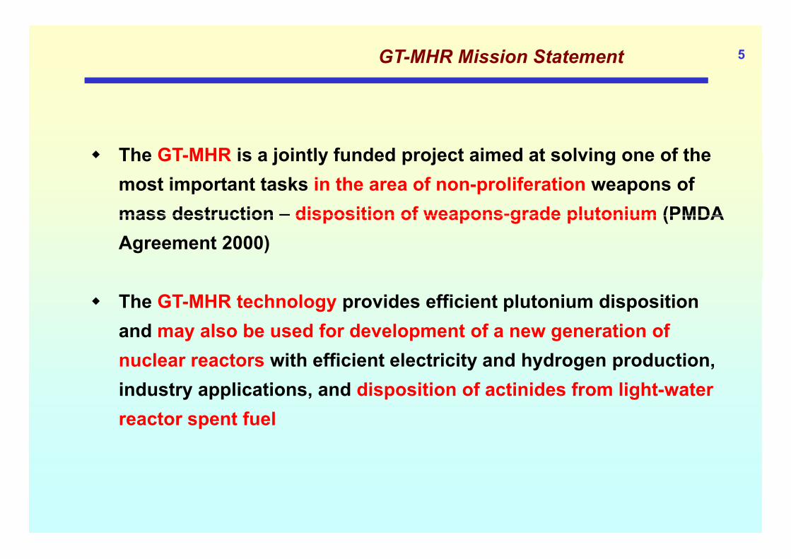
5GT-MHR Mission Statement
The GT MHR is a jointly funded project aimed at solving one of the The GT-MHR is a jointly funded project aimed at solving one of the most important tasks in the area of non-proliferation weapons of mass destruction – disposition of weapons-grade plutonium (PMDAmass destruction disposition of weapons-grade plutonium (PMDA Agreement 2000)
The GT-MHR technology provides efficient plutonium disposition and may also be used for development of a new generation of nuclear reactors with efficient electricity and hydrogen production, industry applications, and disposition of actinides from light-water reactor spent fuel

6GT- MHR Technical Concept
GT-MHR Technical Concept isbased on the following advancedgtechnologies Modular helium nuclear reactors,
in which core destruction and melting is impossible
Ceramic fuel design in the form of small coated particles with s a coated pa t c es tthermo-radiation resistant coatings
Modern technologies based on Modern technologies based on large gas turbines
Electromagnetic bearings High efficiency compact heat
exchangers
Reactor building

7GT-MHR Fuel Design
Fuel particle
Dense pyrocarbonSilicon carbideDense pyrocarbonP b
0.
65 -
1m
m
Porous pyrocarbonFuel kernel (Pu oxide, other HM)
12.5 mm 800
mm
m
Fuel compactThousands of coated Fuel assembly
25-5
0 m
m
fuel particles in a graphite matrix
•Thousands of fuel •compacts•Structural material –reactor graphite
Fuel is operable at the temperatures up to 1600C About 1 billion fuel particles of this type were fabricated and tested in Russia
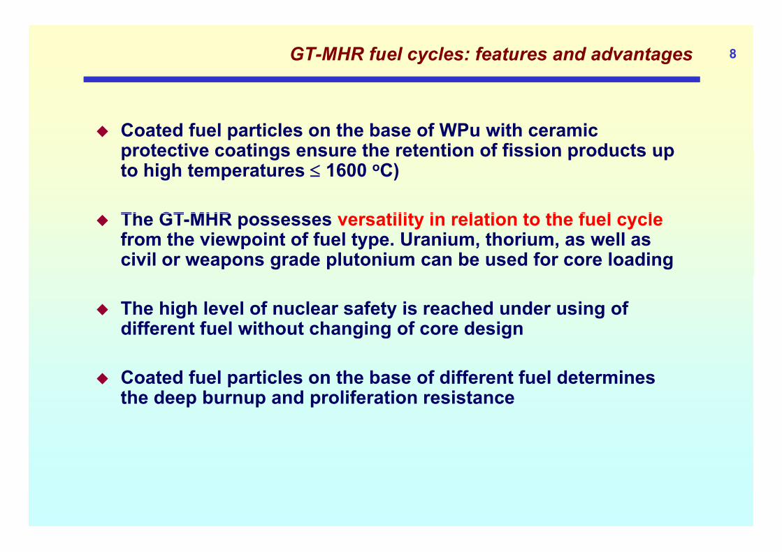
8GT-MHR fuel cycles: features and advantages
Coated fuel particles on the base of WPu with ceramic protective coatings ensure the retention of fission products upprotective coatings ensure the retention of fission products up to high temperatures 1600 oC)
Th GT MHR tilit i l ti t th f l l The GT-MHR possesses versatility in relation to the fuel cyclefrom the viewpoint of fuel type. Uranium, thorium, as well as civil or weapons grade plutonium can be used for core loading
The high level of nuclear safety is reached under using of different fuel without changing of core design
Coated fuel particles on the base of different fuel determines the deep burnup and proliferation resistancethe deep burnup and proliferation resistance

Possibility to Use Different Fuel Cycles in GT-MHR 9
Compositions of weapons grade Pu, civil Pu, Pu in MOX fuel, and also fuel on the basis of low- and high-enriched uranium (LEU and HEU) were considered
Isotopic compositions of fresh fuels
tion
Fuel type Fuel composition Enrichment on fissile i t i U P k l
Fraction of fertile material i f l iti
Op yp p isotopes in U or Pu kernels in fuel composition
1 WGPu Pu-238 (0.1%)+Pu-239 (91.7%) + Pu-240 (6.6%) + Pu-241 (1.2%) + Pu-242 (0.4%)
93 % (Pu fissile) 7 % (Pu-240 and Pu-242)
2 LEU U-235 (14 %) + U-238 (86 %) 14 % (U-235) ~ 86 % (U-238)
2 HEU + Th WGU (15 %) + Th (85 %) 93 % (U-235) ~ 85 % (Th) ~ 1 % (U-238)
4 Ci il P Pu-238 (1%)+Pu-239 (59%) + Pu-240 (24%) + 70 % 29 %(P 240 d P 242)4 Civil Pu ( ) ( ) ( )Pu-241 (11%)+ Pu-242 (5%) (Pu fissile) 29 % (Pu-240 and Pu-242)
5 MOX WGPu (50 %) + U-nat (50 %) 47 % (Pu fissile)
50 % (U-nat) + 3.5 % (Pu-240 and Pu-242)

10WPu disposition scheme
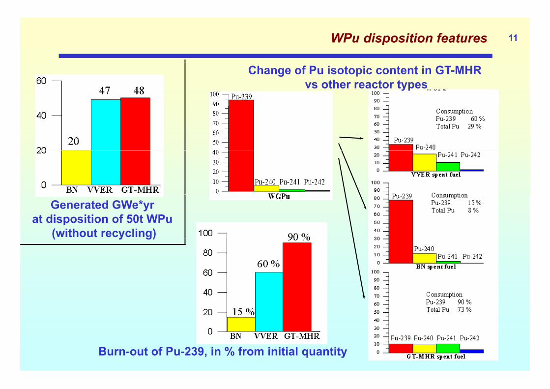
11WPu disposition features
Change of Pu isotopic content in GT-MHR vs other reactor types
Generated GWe*yr at disposition of 50t WPu
(without recycling)( y g)
Burn-out of Pu-239, in % from initial quantity

12GT-MHR has high potential for Pu destruction and proliferation resistance
High degradation of Pu isotopic composition at burnup makes it High degradation of Pu isotopic composition at burnup makes it unattractive for weapons
Fuel particle refractory coatings make fissile material retrieval Fuel particle refractory coatings make fissile material retrieval difficult
Low fissile material volume fraction makes diversion of adequate Low fissile material volume fraction makes diversion of adequate fissile material quantities difficult
Neither a developed process nor a capability for separating fissionable material from GT-MHR spent fuel

13Fuel cycle studies - Qualification of design decisions
Core design Fuel composition design Zoning of fuel and poison Zoning of fuel and poison
loadings in the core volume
CPS positions Fuel reloading scheme Axial shifts of fuel columns
Пирокарбид (PyC)
Карбид кремния (SiC)
Пористый углерод (PyC)
Т й Топливная частица
Топливный керн
ОКБМ
Топливный компакт ТВС I типа ТВС II типа

14Fuel cycle studies – Safety considerations
Temperature coefficient of reactivity Possible positive values for Pu fuel
without fertile and inert diluents
4567891E+5 400
д.
without fertile and inert diluents Choice of optimum burnable Er loading
for compensation (‘Pu 239+Pu 241 mass’ to ‘Er 167 mass’
56789
2
3
1E+4
Xec
135*1/100
Фтеп
300
(Фтеп)
, отн
.ед( Pu-239+Pu-241 mass to Er-167 mass
ratio)
89
2
3
45
1E+3ие, барн Er
a167
200 ых нейтронов
-1E-005
0
1E-005
ти, d
k/dT
. 105 ,
/К
2
3
45678
Сечен
9f
потока
тепловы
4E 005
-3E-005
-2E-005
иент
реактивност Область неопределенности
3
4567891E+2
K K
40a
100
Плотность
п
-6E-005
-5E-005
-4E-005
турный коэффици
начало циклаконец цикла
2 3 4 5 6 7 89 2 3 4 5 6 7 89 2 3 4 5 6 7 890.01 0.10 1.00 10.00E, эВ
2
1E+1
300
K
1200
K
0
300 400 500 600 700 800 900 1000 1100 1200Температура, К
-8E-005
-7E-005
Температу

Studies of reactivity temperature effects at Big Physical Facility (BPF) 15
Proving the possibility of performing reactivity
temperature effects studies for the test specimens in the central graphite insert at BPF.1. Sample outside the core graphite insert at BPF.
Creation of the critical configuration at BPF with a
Reflector ~ 400 mm
Neutron Spectrum
configuration at BPF with a central graphite insert, where the GT-MHR reactor neutron
Active core~ 1000 mm
2. Sample in thecore
SchemeScheme ofofexperimentsexperiments onontemperaturetemperatureeffectseffects
1.E-01
1.E+00
compact
91-3
91-4
spectrum is simulated.
Performing the experiments on
1.E-03
1.E-02
1.E-03 1.E-02 1.E-01 1.E+00 1.E+01 1.E+02 1.E+03 1.E+04 1.E+05 1.E+06 1.E+07
g preactivity temperature effects for the test specimens with different Pu isotopic compositions
Top view
Cooling air inflow 48 mm
Energy (eV) Pu isotopic compositions including the effects of Erburnable poison. 51 mm
B
A

16Fuel cycle studies - Operating conditions
Temperature distributions Estimate local power peaking factors Estimate effects of fuel zoning and Estimate effects of fuel zoning and
column shifting Provide data for TH analysis BOC
0.0 0.5 1.0 1.5 2.0 2.5 3.0 3.5 4.0 4.5
Fuel temperature, oC
0.0 0.5 1.0 1.5 2.0 2.5 3.0 3.5 4.0 4.5
0.0 0.5 1.0 1.5 2.0 2.5 3.0 3.5 4.0 4.5
radial direction from core center
coolant flow direction
EOC
core center

17Fuel cycle studies - Input data for fuel performance analysis
Fuel performance Fuel composition
vs. burnupFuel composition
p Generation of fission
products Fluence calculations
63 15364-gd-15868-er-166
54-xe-13155-cs-13758-ce-14160-nd-14562-sm-14763-eu-153
Fast Neutron Fluence
45-rh-10347-ag-10948-cd-11650-sn-12051-sb-12652-te-132 Fast Neutron Fluence
vs burnup
32 ge 7234-se-8237-rb-8539-y-90
41-nb-9443-tc-99
45 rh 103
Fission Products Histogram
ОКБМ
0 0.0004 0.0008 0.0012 0.0016 0.002
32-ge-72

18Fuel cycle studies – example: Pu fuel design alternatives
№ K l iti K l Di t № Kernel composition Kernel Diameter
0 PuO1.65 (100 %) – reference fuel, SiC in TRISO 200 µm
1 PuO (100 %) as reference but ZrC in TRIZO 200 µm1 PuO1.65 (100 %) – as reference, but ZrC in TRIZO 200 µm
2 PuO1.65 (15 %) + ZrO2 (77,5%)+ Ce2O3 (7,5%) 450 µm
3 PuO1 65(15%) + UO2(15%) + ZrO2(70%) 400 µm1.65( ) 2( ) 2( ) µ
4 PuO1.65(15%) + ThO2(15%) + ZrO2(70%) 400 µm5 PuO1.65(15 %) + ThO2(15%) + ZrO2(40%) + Ce2O3 (30%) 400 µm6 P O (15 %) Z O (85 %) Z C tt l 400 6 PuO1.65 (15 %) + ZrO2(85 %) + gZrC getter layer 400 µm
7 PuO1.65 (15 %) + ZrO2(85 %)+ gZrC in ВРуС 400 µm
8 PuO1 65 (25 %) + ThO2(75 %) + gZrC getter layer 300 µm8 PuO1.65 (25 %) + ThO2(75 %) + gZrC getter layer 300 µm
9 PuO1.65 (25 %) + ThO2(75 %) + gZrC in ВРуС 300 µm
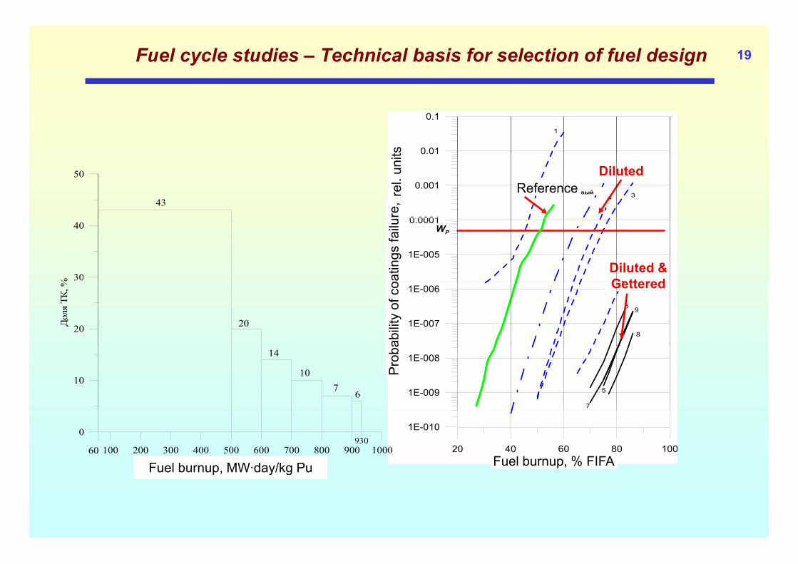
Fuel cycle studies – Technical basis for selection of fuel design 19
0.01
0.11
ts
0 0001
0.001
0.01
н. ед.
3 Базовый4
re,
rel.
unit
ReferenceDiluted 50
43
1E-005
0.0001
азрушения
, отн
2
WP
oatin
gs fa
ilu
Diluted & Gettered30
40
%
1E-007
1E-006
Вероятность ра
6
8
9
abili
ty o
f co Gettered
20Доля ТК
, %
20
1E-009
1E-008
5
7P
roba
10
14
107
6
20 40 60 80 100Выгорание, % FIFA
1E-010
Fuel burnup, % FIFA100 200 300 400 500 600 700 800 900 1000
Выгорание, МВтсут/кг
0
60930
Fuel burnup, MW·day/kg Pup y g

20GT-MHR Selected Basic Fuel
The Coated Particle Design Achieves the RequiredHigh Burnup by the Use of
I t Dil t i th F l K l• Inert Diluent in the Fuel Kernel• Oxygen Getter Coatings• TRISO Coatings
SiC
SiC SiC
SiCSiC
SiC
SiC SiCZrO2
PuO2-x
ZrO2
PuO2-x
SiC
SiC SiC2 2
SiC Oxygen Getter LayerSiC Oxygen Getteron Kernelin Buffer Layer

21WPu disposition and MA transmutation in the GT-MHR
Why WPu to transmute Minor Actinides in the GT-MHR?
Disposition Program presumes effective use of WPu. It is reasonable to admix some Minor Actinides from VVER (LWR)spent fuel
Use of WPu is advisable to provide a stabile Pu isotopic content to use in the GT-MHR (it is more difficult in case of civil Pu)in the GT MHR (it is more difficult in case of civil Pu)
In future it is possible to realize the closed fuel cycle on the basis of Pu from blankets of Fast Reactors
Use advantages of GT MHR flexibility to use different fuel types Use advantages of GT-MHR flexibility to use different fuel types

22WPu disposition and MA transmutation in the GT-MHR
VVER RRMA-(Am,Cm)
VVER RREECCYY Micro particles
Spent fuel,cooling
CCLLIINN
Loading90%PuW+
10%МАNNGG
PuS P f VVER
Initial stage: Initial stage:
Store Pu from VVER for FBRs start-up
GTGT--MHRMHR
Discharge - 25%After 2020 year
Pu from FBR blanketPuPu from wfrom weaponseapons
Back EndBack EndResidual storageResidual storage
g
Heavy Nuclides
Residual storageResidual storage

23WPu disposition and MA transmutation in the GT-MHR
Example: Example: LoadingLoadingEfficiency of WPu and MA utilization
90 % WPu+10 % МА90 % WPu+10 % МА
Discharge Discharge –– 10 %10 %90
100
Isotopes Isotopes inin spent fuelspent fuelPuPu--238238 -- 7.5 %7.5 %
Heavy NuclidesHeavy Nuclides
70
80
fuel
, %
PuPu 238 238 7.5 %7.5 %PuPu--239 239 -- 1.01.0 %%PuPu--240 240 -- 3.53.5 %%PuPu--241 241 -- 1.51.5 %%50
60
Bur
nup
PuPu--242 242 -- 54.354.3 %%AmAm--241 241 -- 0.30.3 %%AmAm--242 242 -- 0.10.1 %%30
40
0 5 10 15 20 25
AmAm--243 243 -- 16.316.3 %%CmCm--244 244 -- 15.215.2 %%CmCm--245 245 -- 0.30.3 %%
MA in loading, %

24WPu disposition and MA transmutation in the GT-MHR
MA activity for open and closed fuel cycle
Open cycle:Open cycle:by 2050 – 330 t (Pu-239 + Pu-241)
from VVERClosed cycle:Closed cycle:
by 2050 – 0,04 t (Pu-239 + Pu-241) from GT-MHR
Open fuel cycle Back End
- VVER StorageU
Open fuel cycle Back End
- VVER StorageU VVER StorageU Closed fuel cycle Back EndVVER RecyclingU
GT-MHR StorageMA
Weapons Pu

25Workscope definition – Studies of deep burning of actinides in MHRs
Consider possible scenarios of deep burning of actinides in MHR-type reactors (various sources of MA and driver fuel, fueltype reactors (various sources of MA and driver fuel, fuel management schemes before and after irradiation in a MHR, choice of the final disposition form)
Choose functionals characterizing the efficiency of transmutation. For the conditions of Russia, a variant of the use of WPu for burning the minor actinides from VVER spent fuel could be considered.
Develop the proposals for the MHR core layouts intended for deep burning of different MA, determine the possibilities of optimization aimed at increase of efficiency of transmutation (e.g. by the choice of fuel placement scheme).

26Workscope definition – Studies of deep burning of actinides in MHRs
Evaluate the uncertainties of the basic characteristics (e.g. neutron-physics or thermodynamic data) and determine their majorneutron physics or thermodynamic data) and determine their major sources
Evaluate the influence of introduction of MA-based compositions into microparticles on safety, e.g. reactivity feedbacks, including transient modes of operation
Analyze the possibility to use Bench Scale Facility for fabrication of coated particles with minor actinidesof coated particles with minor actinides
Determine the design data needs (e.g. in neutron-physics or Determine the design data needs (e.g. in neutron physics or fabrication technology) and evaluate the possibility to obtain them in experiments at facilities in Russia or elsewhere
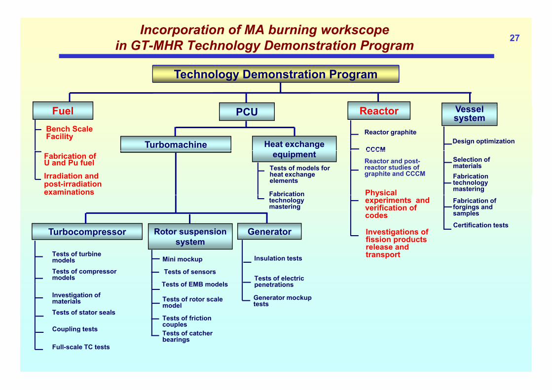
27Incorporation of MA burning workscope
in GT-MHR Technology Demonstration Program
Technology Demonstration Program
V lFuelBench Scale Facility
PCU
Heat exchange Turbomachine
Reactor
Reactor graphite
CCCM
Vessel system
Design optimization
Fabrication ofU and Pu fuelIrradiation and post-irradiation examinations
equipmentTests of models for heat exchange elements
Fabrication
CCCM
Reactor and post-reactor studies of graphite and CCCM
Physical
Selection of materialsFabricationtechnologymastering
Fabricationtechnologymastering
Turbocompressor Rotor suspension t
Generator
Physical experiments and verification of codes
Investigations of fission products
Fabrication offorgings and samples
Certification tests
Tests of turbine modelsTests of compressor models
system
Mini mockup
Tests of sensors
Tests of EMB models
Insulation tests
Tests of electric penetrations
fission products release and transport
Investigation of materialsTests of stator seals
Coupling tests
Tests of EMB models
Tests of rotor scale model
Tests of friction couples
penetrations
Generator mockup tests
Coupling tests
Full-scale TC tests
pTests of catcher bearings

28Modifications in the Planning in GT-MHR Project
(or setting of a new Project planning)
From “Development Plans” to Workscope Descriptions with account for the
extension of the Project Mission by burning of MA

Example of a Closed Fuel Cycle based on Three Types of Reactors 29

Estimation of GT-MHR Efficiency for Burning of MAs and WG Plutonium 30

31Estimation of GT-MHR Efficiency for Burning of MAs and Civil Plutonium
32Estimation of GT-MHR Efficiency for Burning of MAs and Plutonium
The maximum possible content of MAs is about 25% forweapons-grade plutonium and 10% for reactor-grade plutonium,both are values are drastically higher than the MA contentassumed for VVER or fast reactor fuels (usually 5%).( y %)
Preliminary analysis of neutronic characteristics of the coreloaded with different-grade plutonium and additionally with MAsshows that:
in the absence of burnable poison in the core additionally loadedMAs make it possible to balance the reactivity change during the fuelMAs make it possible to balance the reactivity change during the fuellifetime and provide the negative temperature feedback.
average burnup of all transuranium isotopes is not less than50% h50% h.a.
initially loaded fissile plutonium in once-through pass in the corecan be burnt out by 60%. Burnout of all MAs varies from about 20% toy60% h.a.

33Technology Development Program. Reactor physics
ASTRA –critical test facilityt NRC K h t I tit tat NRC Kurchatov Institute,
Moscow
Test goalsTest goals Investigations of neutron characteristics of
annular cores (power distribution etc) Investigation of control rods effectivenessg After upgrade - Measurements of
temperature coefficients (20…600 оС)

34Technology Development Program. Reactor physics
Big Physical Facility (BPF) –critical test facilityt IPPE Ob i kat IPPE, Obninsk
Test goalsTest goals Investigations of characteristics for HTGR
fuel compositions with Pu and MA Special measures to simulate HTGR p
spectrum at fast critical facility

FUEL PROCESS DEVELOPMENTBENCH SCALE FACILITY REPRESENTS ALL FUEL FABRICATION STEPS
FUEL PROCESS DEVELOPMENTBENCH SCALE FACILITY REPRESENTS ALL FUEL FABRICATION STEPS
Solution and Fuel Kernel Fabrication Glove Boxes
Emission Spectrometer for Quality Control
Fuel Kernel Processingy
CoatersOff Gas Treatment System
Fuel Kernel Sintering Furnace Bochvar Institute, Moscow
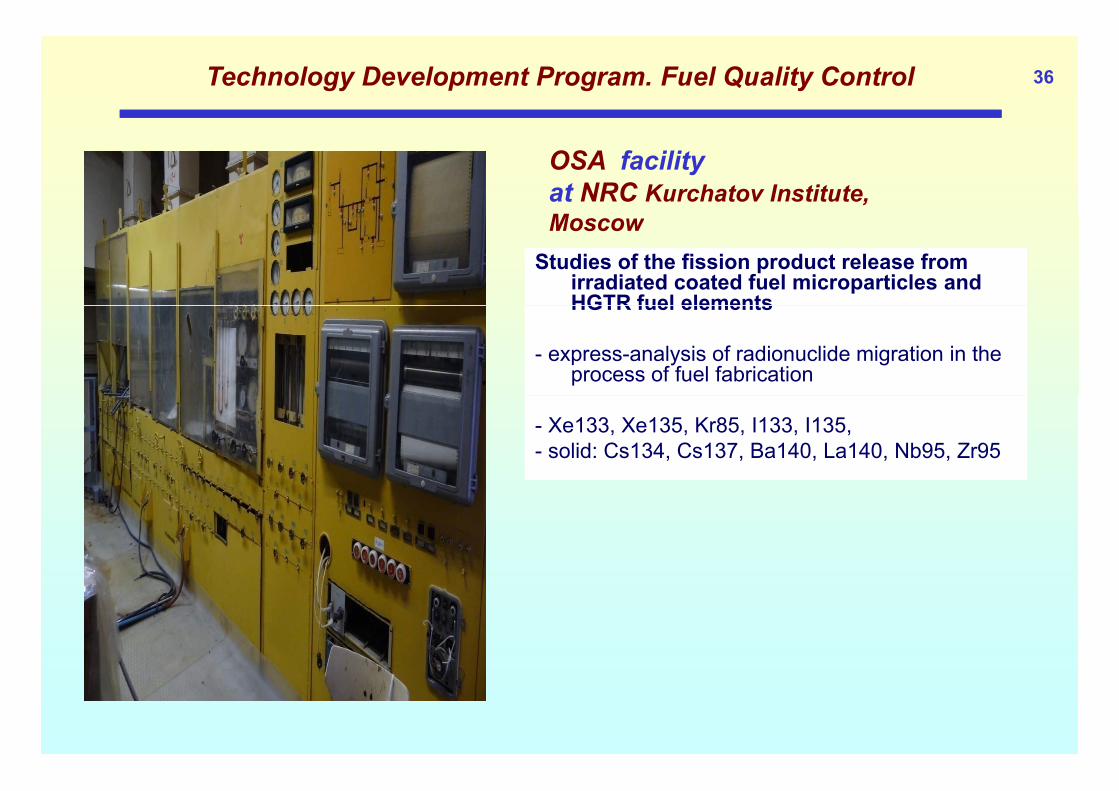
36Technology Development Program. Fuel Quality Control
OSA facility at NRC Kurchatov Institute, MMoscow
Studies of the fission product release from irradiated coated fuel microparticles and HGTR fuel elementsHGTR fuel elements
- express-analysis of radionuclide migration in the process of fuel fabrication
- Xe133, Xe135, Kr85, I133, I135,- solid: Cs134, Cs137, Ba140, La140, Nb95, Zr95
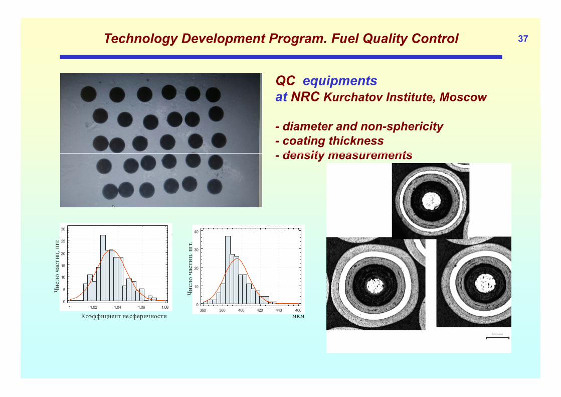
37Technology Development Program. Fuel Quality Control
QC equipments at NRC Kurchatov Institute, Moscow
- diameter and non-sphericity- coating thickness
density measurements- density measurements
т.
40
т. 25
30
исло
частиц,
шт
10
20
30
Число частиц
, ш
5
10
15
20
Чи
мкм360 380 400 420 440 460
0
Ч
Коэффициент несферичности1 1,02 1,04 1,06 1,08
0
5

38Technology Development Program. Fuel Quality Control
Planning of Irradiation Tests
design of capsules- design of capsules- selection of samples and pre-irradiation control
Instrumented Irradiation Capsule

FUEL QUALIFICATIONIRRADIATION AND POST-IRRADIATION EXAMINATION FACILITIES
Post Irradiation Examination Facilities SM-3 and RBT-6 Test Reactors
52
6ID 3
Post Irradiation Examination Facilities
4
44
3
3
1
2
17
Instrumented Irradiation Capsule
Well-Equipped Hot CellsCapsule NIIAR, Dimitrovgrad
40Conclusions
Hope on the versatile role of MHRs in the strategy of Nuclear Power development should be confirmed by comprehensive studies
It is possible to study different fuel cycles on the basis of a unified core design
Peculiarities of fuel cycle studies and technology issues should be thoroughly addressed
Investigations of introduction of MA in the loaded MHR fuel could be started as a neutron physics exercise (including nuclide flows)be started as a neutron physics exercise (including nuclide flows)
Workscope definition and approach for HTGR Deep Burnup studies should be consistently elaborated taking into account nationalshould be consistently elaborated taking into account national nuclear policy
Examples of conceptual developments are very useful for scientific p p p ydiscussions and elaboration of recommendations