Embed Size (px)
Citation preview

Engineering Designand Technology Series
Student’s Guide to Learning SolidWorks® Software
Dassault Systèmes - SolidWorks Corporation
300 Baker Avenue
Concord, Massachusetts 01742 USA
Phone: +1-800-693-9000
Outside the U.S.: +1-978-371-5011
Fax: +1-978-371-7303
Email: [email protected]
Web: http://www.solidworks.com/education

© 1995-2010, Dassault Systèmes SolidWorks Corporation, a Dassault Systèmes S.A. company,300 Baker Avenue, Concord, Mass. 01742 USA.
All Rights Reserved.
The information and the software discussed in this document are subject to change without notice and are not commitments by Dassault Systèmes SolidWorks Corporation (DS SolidWorks).
No material may be reproduced or transmitted in any form or by any means, electronic or mechanical, for any purpose without the express written permission of DS SolidWorks.
The software discussed in this document is furnished under a license and may be used or copied only in accordance with the terms of this license. All warranties given by DS SolidWorks as to the software and documentation are set forth in the SolidWorks Corporation License and Subscription Service Agreement, and nothing stated in, or implied by, this document or its contents shall be considered or deemed a modification or amendment of such warranties.
Patent Notices for SolidWorks Standard, Premium, and Professional Products
U.S. Patents 5,815,154; 6,219,049; 6,219,055; 6,603,486; 6,611,725; 6,844,877; 6,898,560; 6,906,712; 7,079,990; 7,184,044; 7,477,262; 7,502,027; 7,558,705; 7,571,079; 7,643,027 and foreign patents, (e.g., EP 1,116,190 and JP 3,517,643).
U.S. and foreign patents pending.
Trademarks and Other Notices for All SolidWorks Products
SolidWorks, 3D PartStream.NET, 3D ContentCentral, PDMWorks, eDrawings, and the eDrawings logo are registered trademarks and FeatureManager is a jointly owned registered trademark of DS SolidWorks.
SolidWorks Enterprise PDM, SolidWorks Simulation, SolidWorks Flow Simulation, and SolidWorks 2010 are product names of DS SolidWorks.
CircuitWorks, Feature Palette, FloXpress, PhotoWorks, TolAnalyst, and XchangeWorks are trademarks of DS SolidWorks.
FeatureWorks is a registered trademark of Geometric Ltd.
Other brand or product names are trademarks or registered trademarks of their respective holders.
Document Number: PMS0118-ENG
COMMERCIAL COMPUTERSOFTWARE - PROPRIETARY
U.S. Government Restricted Rights. Use, duplication, or disclosure by the government is subject to restrictions as set forth in FAR 52.227-19 (Commercial Computer Software - Restricted Rights), DFARS 227.7202 (Commercial Computer Software and Commercial Computer Software Documentation), and in the license agreement, as applicable.
Contractor/Manufacturer:Dassault Systèmes SolidWorks Corporation, 300 Baker Avenue, Concord, Massachusetts 01742 USA
Copyright Notices for SolidWorks Standard, Premium, and Professional Products
Portions of this software © 1990-2010 Siemens Product Lifecycle Management Software III (GB) Ltd.
Portions of this software © 1998-2010 Geometric Ltd.
Portions of this software © 1986-2010 mental images GmbH & Co. KG.
Portions of this software © 1996-2010 Microsoft Corporation. All rights reserved.
Portions of this software © 2000-2010 Tech Soft 3D.
Portions of this software © 1998-2010 3Dconnexion.
This software is based in part on the work of the Independent JPEG Group. All Rights Reserved.
Portions of this software incorporate PhysX™ by NVIDIA 2006-2010.
Portions of this software are copyrighted by and are the property of UGS Corp. © 2010.
Portions of this software © 2001-2010 Luxology, Inc. All Rights Reserved, Patents Pending.
Portions of this software © 2007-2010 DriveWorks Ltd
Copyright 1984-2010 Adobe Systems Inc. and its licensors. All rights reserved. Protected by U.S. Patents 5,929,866; 5,943,063; 6,289,364; 6,563,502; 6,639,593; 6,754,382; Patents Pending.
Adobe, the Adobe logo, Acrobat, the Adobe PDF logo, Distiller and Reader are registered trademarks or trademarks of Adobe Systems Inc. in the U.S. and other countries.
For more copyright information, in SolidWorks see Help > About SolidWorks.
Other portions of SolidWorks 2010 are licensed from DS SolidWorks licensors.
Copyright Notices for SolidWorks Simulation
Portions of this software © 2008 Solversoft Corporation.
PCGLSS © 1992-2007 Computational Applications and System Integration, Inc. All rights reserved.
Portions of this product are distributed under license from DC Micro Development, Copyright © 1994-2005 DC Micro Development, Inc. All rights reserved.

Student’s Guide to Learning SolidWorks Software iii
Introduction v
Lesson 1: Using the Interface 1
Lesson 2: Basic Functionality 11
Lesson 3: The 40-Minute Running Start 27
Lesson 4: Assembly Basics 37
Lesson 5: SolidWorks Toolbox Basics 55
Lesson 6: Drawing Basics 69
Lesson 7: SolidWorks eDrawings Basics 79
Lesson 8: Design Tables 93
Lesson 9: Revolve and Sweep Features 103
Lesson 10: Loft Features 111
Lesson 11: Visualization 119
Lesson 12: SolidWorks SimulationXpress 131
Glossary 141
Appendix A: Certified SolidWorks Associate Program 147
Contents

Contents
iv Student’s Guide to Learning SolidWorks Software

Student’s Guide to Learning SolidWorks Software v
i
Introduction
SolidWorks Tutorials
Student’s Guide to Learning SolidWorks Software is a companion resource and supplement for the SolidWorks Tutorials. Many of the exercises in Student’s Guide to
Learning SolidWorks Software use material from the SolidWorks Tutorials.
Accessing the SolidWorks Tutorials
To start the SolidWorks Tutorials, click Help, SolidWorks
Tutorials. The SolidWorks window is resized and a second window appears next to it with a list of the available tutorials. There are over 40 lessons in the SolidWorks Tutorials. As you move the pointer over the links, an illustration of the tutorial will appear at the bottom of the window. Click the desired link to start that tutorial.
TIP: When you use SolidWorks Simulation to perform static engineering analysis, click Help, Simulation, Simulation Online Tutorial to access over 20 lessons and over 35 verification problems. Click Tools, Add-ins to activate SolidWorks Simulation.

Introduction
vi Student’s Guide to Learning SolidWorks Software
Conventions
Set your screen resolution to 1280x1024 for optimal viewing of the tutorials.
The following icons appear in the tutorials:
Moves to the next screen in the tutorial.
Represents a note or tip. It is not a link; the information is below the icon. Notes and tips provide time-saving steps and helpful hints.
You can click most toolbar buttons that appear in the lessons to flash the corresponding SolidWorks button.
Open File or Set this option automatically opens the file or sets the option.
A closer look at... links to more information about a topic. Although not required to complete the tutorial, it offers more detail on the subject.
Why did I... links to more information about a procedure, and the reasons for the method given. This information is not required to complete the tutorial.
Show me... demonstrates with a video.
Printing the SolidWorks Tutorials
If you like, you can print the SolidWorks Tutorials by following this procedure:
1 On the tutorial navigation toolbar, click Show.
This displays the table of contents for the SolidWorks Tutorials.
2 Right-click the book representing the lesson you wish to print and select Print... from the shortcut menu.
The Print Topics dialog box appears.
3 Select Print the selected heading and all subtopics, and click OK.
4 Repeat this process for each lesson that you want to print.

Student’s Guide to Learning SolidWorks Software 1
1
Lesson 1: Using the Interface
Goals of This Lesson
� Become familiar with the Microsoft Windows® interface.
� Become familiar with the SolidWorks user interface.
Before Beginning This Lesson
� Verify that Microsoft Windows is loaded and running on your classroom/lab computers.
� Verify that the SolidWorks software is loaded and running on your classroom/lab computers in accordance with your SolidWorks license.
� Load the lesson files from the Educator Resources link.
Competencies for Lesson 1
You develop the following competencies in this lesson:
� Engineering: Knowledge of an engineering design industry software application.
� Technology: Understand file management, search, copy, save, starting and exiting programs.
SolidWorks education suite contains 80 eLearning tutorials in engineering design, simulation, sustainability and analysis.
Lesson 1: Using the Interface
2 Student’s Guide to Learning SolidWorks Software
Active Learning Exercise — Using the Interface
Start the SolidWorks application, search for a file, save the file, save the file with a new name, and review the basic user interface.
Starting a Program
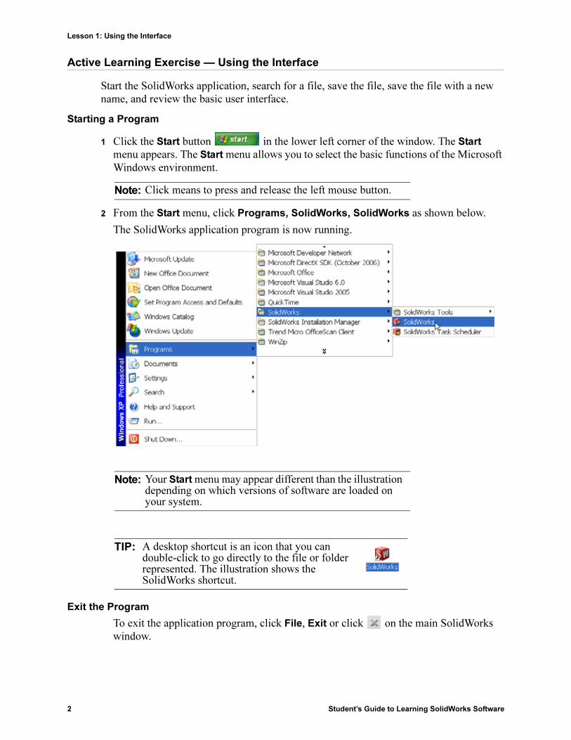
1 Click the Start button in the lower left corner of the window. The Start menu appears. The Start menu allows you to select the basic functions of the Microsoft Windows environment.
2 From the Start menu, click Programs, SolidWorks, SolidWorks as shown below.
The SolidWorks application program is now running.
Exit the Program
To exit the application program, click File, Exit or click on the main SolidWorks window.
Note: Click means to press and release the left mouse button.
Note: Your Start menu may appear different than the illustration depending on which versions of software are loaded on your system.
TIP: A desktop shortcut is an icon that you can double-click to go directly to the file or folder represented. The illustration shows the SolidWorks shortcut.

Lesson 1: Using the Interface
Student’s Guide to Learning SolidWorks Software 3
Searching for a File or Folder
You can search for files (or folders containing files). This is useful if you cannot remember the exact name of the file that you need.
3 Click Start, Search to open the Windows Desktop Search dialog box. Select Click
here to use Search Companion to open the Search Results dialog box.
4 Click All files and folders. Search for the SolidWorks part dumbell. To do this, enter dumb* in the All or part of the
file name: field.
Specifying what to search for and where to search for it is known as defining the search criteria.
5 Click Search.
The files and folders that match the search criteria appear in the Search Results window.
Opening an Existing File
6 Double-click on the SolidWorks part file Dumbell.
This opens the Dumbell file in SolidWorks. If the SolidWorks application program is not running when you double-click on the part file name, the system runs the SolidWorks application program and then opens the part file that you selected.
You could have also opened the file by selecting File, Open, and typing or browsing to a file name or by selecting a file name from the File menu in SolidWorks. SolidWorks lists the last several files that you had open.
Saving a File
7 Click Save on the Standard toolbar to save changes to a file.
It is a good idea to save the file that you are working whenever you make changes to it.
TIP: The asterisk (*) is a wild card. The wild card allows you to enter part of a file name and search for all files and folders that contain that piece.
TIP: You can also begin a search by right-clicking on the Start button and selecting Search. Right-click means to press and release the right button on your mouse.
TIP: Use the left mouse button to double-click. Double-clicking with the left mouse button is often a quick way of opening files from a folder.

Lesson 1: Using the Interface
4 Student’s Guide to Learning SolidWorks Software
Copying a File
Notice that Dumbell is not spelled correctly. It is supposed to have two “b’s”.
1 Click File, Save As to save a copy of the file with a new name.
The Save As window appears. This window shows you in which folder the file is currently located, the file name, and the file type.
2 In the File Name field change the name to Dumbbell and click Save.
A new file is created with the new name. The original file still exists. The new file is an exact copy of the file as it exists at the moment that it is copied.
Resizing Windows
SolidWorks, like many applications, uses windows to show your work. You can change the size of each window.
1 Move the cursor along the edge of a window until the shape of the cursor appears to be a two-headed arrow.
2 While the cursor still appears to be a two-headed arrow, hold down the left mouse button and drag the window to a different size.
3 When the window appears to be the size that you wish, release the mouse button.
Windows can have multiple panels. You can resize these panels relative to each other.
4 Move the cursor along the border between two panels until the cursor appears to be two parallel lines with perpendicular arrows.
5 While the cursor still appears to be two parallel lines with perpendicular arrows, hold down the left mouse button and drag the panel to a different size.
6 When the panel appears to be the size that you wish, release the mouse button.
SolidWorks Windows
SolidWorks windows have two panels. One panel provides non-graphic data. The other panel provides graphic representation of the part, assembly, or drawing.
The leftmost panel of the window contains the FeatureManager® design tree, PropertyManager and ConfigurationManager.
Lesson 1: Using the Interface
Student’s Guide to Learning SolidWorks Software 5
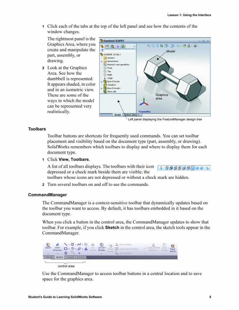
1 Click each of the tabs at the top of the left panel and see how the contents of the window changes.
The rightmost panel is the Graphics Area, where you create and manipulate the part, assembly, or drawing.
2 Look at the Graphics Area. See how the dumbbell is represented. It appears shaded, in color and in an isometric view. These are some of the ways in which the model can be represented very realistically.
Toolbars
Toolbar buttons are shortcuts for frequently used commands. You can set toolbar placement and visibility based on the document type (part, assembly, or drawing). SolidWorks remembers which toolbars to display and where to display them for each document type.
1 Click View, Toolbars.
A list of all toolbars displays. The toolbars with their icon depressed or a check mark beside them are visible; the toolbars whose icons are not depressed or without a check mark are hidden.
2 Turn several toolbars on and off to see the commands.
CommandManager
The CommandManager is a context-sensitive toolbar that dynamically updates based on the toolbar you want to access. By default, it has toolbars embedded in it based on the document type.
When you click a button in the control area, the CommandManager updates to show that toolbar. For example, if you click Sketch in the control area, the sketch tools appear in the CommandManager.
Use the CommandManager to access toolbar buttons in a central location and to save space for the graphics area.
Model
Graphicsarea
Left panel displaying the FeatureManager design tree
control area

Lesson 1: Using the Interface
6 Student’s Guide to Learning SolidWorks Software
Mouse Buttons
Mouse buttons operate in the following ways:
� Left – Selects menu items, entities in the graphics area, and objects in the FeatureManager design tree.
� Right – Displays the context-sensitive shortcut menus.
� Middle – Rotates, pans, and zooms the view of a part or an assembly, and pans in a drawing.
Shortcut Menus
Shortcut menus give you access to a wide variety of tools and commands while you work in SolidWorks. When you move the pointer over geometry in the model, over items in the FeatureManager design tree, or over the SolidWorks window borders, right-clicking pops up a shortcut menu of commands that are appropriate for wherever you clicked.
You can access the "more commands menu" by selecting the double-down arrows in the menu. When you select the double-down arrows or pause the pointer over the double-down arrows, the shortcut menu expands to offer more menu items.
The shortcut menu provides an efficient way to work without continually moving the pointer to the main pull-down menus or the toolbar buttons.
Getting Online Help
If you have questions while you are using the SolidWorks software, you can find answers in several ways:
� Click Help on the Standard toolbar.
� Click Help, SolidWorks Help Topics in the menu bar.
� While in a command, click Help in the dialog.

Lesson 1: Using the Interface
Student’s Guide to Learning SolidWorks Software 7
Lesson 1 — 5 Minute Assessment
Name: _______________________________Class: _________ Date:_______________
Directions: Answer each question by writing the correct answer or answers in the space
provided or circle the answer as directed.
1 Search for the SolidWorks part file Paper Towel Base. How did you find it?
_____________________________________________________________________
_____________________________________________________________________
2 What is the quickest way to bring up the Search window?
_____________________________________________________________________
3 How do you open the file from the Search Results window?
_____________________________________________________________________
4 How do you start the SolidWorks program?
_____________________________________________________________________
5 What is the quickest way to start the SolidWorks program?
_____________________________________________________________________
Lesson 1: Using the Interface
8 Student’s Guide to Learning SolidWorks Software
Lesson 1 Vocabulary Worksheet
Name: _______________________________Class: _________ Date:_______________
Fill in the blanks with the words that are defined by the clues.
1 Shortcuts for collections of frequently used commands: ________________________
2 Command to create a copy of a file with a new name: __________________________
3 One of the areas that a window is divided into: _______________________________
4 The graphic representation of a part, assembly, or drawing: ______________________
5 Character that you can use to perform wild card searches: _______________________
6 Area of the screen that displays the work of a program: _________________________
7 Icon that you can double-click to start a program: _____________________________
8 Action that quickly displays shortcut menus of frequently used or detailed commands:
_____________________________________________________________________
9 Command that updates your file with changes that you have made to it: ____________
_____________________________________________________________________
10 Action that quickly opens a part or program: _________________________________
11 The program that helps you create parts, assemblies, and drawings: _______________
12 Panel of the SolidWorks window that displays a visual representation of your parts, assemblies, and drawings: ________________________________________________
13 Technique that allows you to find all files and folders that begin or end with a specified set of characters: _______________________________________________________

Lesson 1: Using the Interface
Student’s Guide to Learning SolidWorks Software 9
Lesson Summary
� The Start menu is where you go to start programs or find files.
� You can use wild cards to search for files.
� There are short cuts such as right-click and double-click that can save you work.
� File, Save allows you to save updates to a file and File, Save As allows you to make a copy of a file.
� You can change the size and location of windows as well as panels within windows.
� The SolidWorks window has a Graphics Area that shows 3D representations of your models.

Lesson 1: Using the Interface
10 Student’s Guide to Learning SolidWorks Software

Student’s Guide to Learning SolidWorks Software 11
2
Lesson 2: Basic Functionality
Goals of This Lesson
� Understand the basic functionality of the SolidWorks software.
� Create the following part:
Before Beginning This Lesson
Complete Lesson 1: Using the Interface.
SolidWorks supports student teams in Formula Student, FSAE and other regional and national competitions, for software sponsorship, go to www.solidworks.com/student.

Lesson 2: Basic Functionality
12 Student’s Guide to Learning SolidWorks Software
Competencies for Lesson 2
You develop the following competencies in this lesson:
� Engineering: Develop a 3D part based on a selected plane, dimensions, and features. Apply the design process to develop the box or switch plate out of cardboard or other material. Develop manual sketching techniques by drawing the switch plate.
� Technology: Apply a windows based graphical user interface.
� Math: Understand units of measurement, adding and subtracting material, perpendicularity, and the x-y-z coordinate system.

Lesson 2: Basic Functionality
Student’s Guide to Learning SolidWorks Software 13
Active Learning Exercises — Creating a Basic Part
Use SolidWorks to create the box shown at the right.
The step-by-step instructions are given below.
Create a New Part Document
1 Create a new part. Click
New on the Standard toolbar.
The New SolidWorks
Document dialog box appears.
2 Click the Tutorial tab.
3 Select the Part icon.
4 Click OK.
A new part document window appears.
Base Feature
The Base feature requires:
� Sketch plane – Front (default plane)
� Sketch profile – 2D Rectangle
� Feature type – Extruded boss feature
Open a Sketch
1 Click to select the Front plane in the FeatureManager design tree.
2 Open a 2D sketch. Click Sketch on the Sketch toolbar.
Confirmation Corner
When many SolidWorks commands are active, a symbol or a set of symbols appears in the upper right corner of the graphics area. This area is called the Confirmation Corner.
Sketch Indicator
When a sketch is active, or open, a symbol appears in the confirmation corner that looks like the Sketch tool. It provides a visual reminder that you are active in a sketch. Clicking this symbol exits the sketch saving your changes. Clicking the red X exits the sketch discarding your changes.

Lesson 2: Basic Functionality
14 Student’s Guide to Learning SolidWorks Software
When other commands are active, the confirmation corner displays two symbols: a check mark and an X. The check mark executes the current command. The X cancels the command.
Overview of the SolidWorks Window
� A sketch origin appears in the center of the graphics area.
� Editing Sketch1 appears in the status bar at the bottom of the screen.
� Sketch1 appears in the FeatureManager design tree.
� The status bar shows the position of the pointer, or sketch tool, in relation to the sketch origin.
Sketch a Rectangle
1 Click Corner Rectangle on the Sketch toolbar.
2 Click the sketch origin to start the rectangle.
3 Move the pointer up and to the right, to create a rectangle.
4 Click the mouse button again to complete the rectangle.
Status bar
Graphics area
Sketch origin
Menu bar
FeatureManager design tree
Confirmation Corner with sketch indicator
Reference Triad
CommandManager
Heads-up View Toolbar

Lesson 2: Basic Functionality
Student’s Guide to Learning SolidWorks Software 15
Add Dimensions
1 Click Smart Dimension on the Dimensions/Relations toolbar.
The pointer shape changes to .
2 Click the top line of the rectangle.
3 Click the dimension text location above the top line.
The Modify dialog box is displayed.
4 Enter 100. Click or press Enter.
5 Click the right edge of the rectangle.
6 Click the dimension text location. Enter 65. Click .
The top segment and the remaining vertices are displayed in black. The status bar in the lower-right corner of the window indicates that the sketch is fully defined.
Changing the Dimension Values
The new dimensions for the box are 100mm x 60mm. Change the dimensions.
1 Double-click 65.
The Modify dialog box appears.
2 Enter 60 in the Modify dialog box.
3 Click .
Extrude the Base Feature.
The first feature in any part is called the Base Feature. In this exercise, the base feature is created by extruding the sketched rectangle.
1 Click Extruded Boss/Base on the Features toolbar.
The Extrude PropertyManager appears. The view of the sketch changes to trimetric.
TIP: If the Features toolbar is not visible (active), you may also access the feature commands from the CommandManager.

Lesson 2: Basic Functionality
16 Student’s Guide to Learning SolidWorks Software
2 Preview graphics.
A preview of the feature is shown at the default depth.
Handles appear that can be used to drag the preview to the desired depth. The handles are colored magenta for the active direction and gray for inactive direction. A callout shows the current depth value.
The cursor changes to . If you want to create the feature now, click the right mouse button. Otherwise, you can make additional changes to the settings. For example, the depth of extrusion can be changed by dragging the dynamic handle with the mouse or by setting a value in the PropertyManager.
3 Extrude feature settings.
Change the settings as shown.
• End Condition = Blind
• (Depth) = 50
4 Create the extrusion. Click OK .
The new feature, Extrude1, is displayed in the FeatureManager design tree.
TIP:
The OK button on the PropertyManager is just one way to complete the command.
A second method is the set of OK/Cancel buttons in the confirmation corner of the graphics area.
A third method is the right-mouse shortcut menu that includes OK, among other options.
Sketch
Preview
Handle
On-screen Scale
Lesson 2: Basic Functionality
Student’s Guide to Learning SolidWorks Software 17
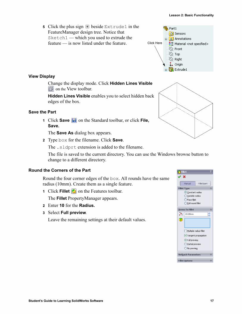
5 Click the plus sign beside Extrude1 in the FeatureManager design tree. Notice that Sketch1 — which you used to extrude the feature — is now listed under the feature.
View Display
Change the display mode. Click Hidden Lines Visible
on the View toolbar.
Hidden Lines Visible enables you to select hidden back edges of the box.
Save the Part
1 Click Save on the Standard toolbar, or click File,
Save.
The Save As dialog box appears.
2 Type box for the filename. Click Save.
The .sldprt extension is added to the filename.
The file is saved to the current directory. You can use the Windows browse button to change to a different directory.
Round the Corners of the Part
Round the four corner edges of the box. All rounds have the same radius (10mm). Create them as a single feature.
1 Click Fillet on the Features toolbar.
The Fillet PropertyManager appears.
2 Enter 10 for the Radius.
3 Select Full preview.
Leave the remaining settings at their default values.
Click Here
Lesson 2: Basic Functionality
18 Student’s Guide to Learning SolidWorks Software
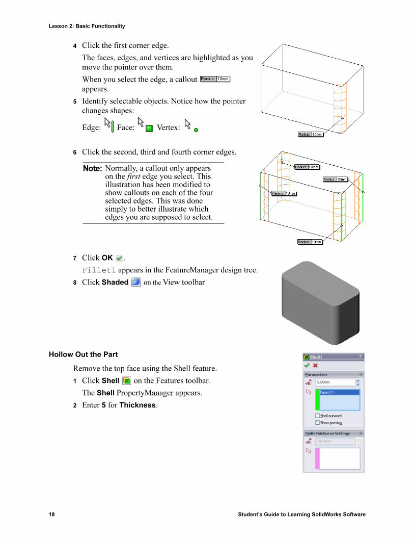
4 Click the first corner edge.
The faces, edges, and vertices are highlighted as you move the pointer over them.
When you select the edge, a callout appears.
5 Identify selectable objects. Notice how the pointer changes shapes:
Edge: Face: Vertex:
6 Click the second, third and fourth corner edges.
7 Click OK .
Fillet1 appears in the FeatureManager design tree.
8 Click Shaded on the View toolbar
Hollow Out the Part
Remove the top face using the Shell feature.
1 Click Shell on the Features toolbar.
The Shell PropertyManager appears.
2 Enter 5 for Thickness.
Note: Normally, a callout only appears on the first edge you select. This illustration has been modified to show callouts on each of the four selected edges. This was done simply to better illustrate which edges you are supposed to select.

Lesson 2: Basic Functionality
Student’s Guide to Learning SolidWorks Software 19
3 Click the top face.
4 Click .
Extruded Cut Feature
The Extruded Cut feature removes material. To make an extruded cut requires a:
� Sketch plane – In this exercise, the face on the right-hand side of the part.
� Sketch profile – 2D circle
Open a Sketch
1 To select the sketch plane, click the right-hand face of the box.
2 Click Right on the Standard Views toolbar.
The view of the box turns. The selected model face is facing you.
3 Open a 2D sketch. Click Sketch on the Sketch toolbar.
Top Face
Pick this face

Lesson 2: Basic Functionality
20 Student’s Guide to Learning SolidWorks Software
Sketch the Circle
1 Click Circle on the Sketch Tools toolbar.
2 Position the pointer where you want the center of the circle. Click the left mouse button.
3 Drag the pointer to sketch a circle.
4 Click the left mouse button again to complete the circle.
Dimension the Circle
Dimension the circle to determine its size and location.
1 Click Smart Dimension on the Dimensions/Relations toolbar.
2 Dimension the diameter. Click on the circumference of the circle. Click a location for the dimension text in the upper right corner. Enter 10.
3 Create a horizontal dimension. Click the circumference of the circle. Click the left most vertical edge. Click a location for the dimension text below the bottom horizontal line. Enter 25.
4 Create a vertical dimension. Click the circumference of the circle. Click the bottom most horizontal edge. Click a location for the dimension text to the right of the sketch. Enter 40.
Extrude the Sketch
1 Click Extruded Cut on the Features toolbar.
The Extrude PropertyManager appears.
2 Select Through All for the end condition.
3 Click .
Lesson 2: Basic Functionality
Student’s Guide to Learning SolidWorks Software 21
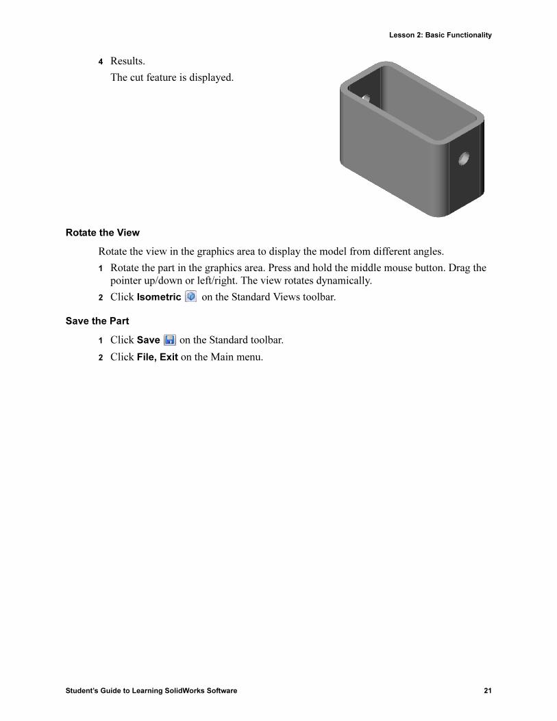
4 Results.
The cut feature is displayed.
Rotate the View
Rotate the view in the graphics area to display the model from different angles.
1 Rotate the part in the graphics area. Press and hold the middle mouse button. Drag the pointer up/down or left/right. The view rotates dynamically.
2 Click Isometric on the Standard Views toolbar.
Save the Part
1 Click Save on the Standard toolbar.
2 Click File, Exit on the Main menu.

Lesson 2: Basic Functionality
22 Student’s Guide to Learning SolidWorks Software
Lesson 2 — 5 Minute Assessment
Name: _______________________________Class: _________ Date:_______________
Directions: Answer each question by writing the correct answer or answers in the space
provided or circle the answer as directed.
1 How do you start a SolidWorks session?
_____________________________________________________________________
_____________________________________________________________________
2 Why do you create and use Document Templates?
_____________________________________________________________________
_____________________________________________________________________
3 How do you start a new Part Document?
_____________________________________________________________________
4 What features did you use to create the box?
_____________________________________________________________________
5 True or False. SolidWorks is used by designers and engineers.
_____________________________________________________________________
6 A SolidWorks 3D model consists of _________ _________ ________.
_____________________________________________________________________
7 How do you open a sketch?
_____________________________________________________________________
8 What does the Fillet feature do?
_____________________________________________________________________
9 What does the Shell feature do?
_____________________________________________________________________
10 What does the Cut-Extrude feature do?
_____________________________________________________________________
11 How do you change a dimension value?
_____________________________________________________________________

Lesson 2: Basic Functionality
Student’s Guide to Learning SolidWorks Software 23
Exercises and Projects — Designing a Switch Plate
Switch plates are required for safety. They cover live electrical wires and protect people from electric shock. Switch plates are found in every home and school.
Caution: Do not use metal rulers near switch plates attached to a live wall outlet.
Tasks
1 Measure a single light plate switch cover.
_______________________________
_______________________________
_______________________________
2 Using paper and pencil, manually sketch the light plate switch cover.
3 Label the dimensions.
4 What is the base feature for the light plate switch cover?
_______________________________
_______________________________
_______________________________
_______________________________
5 Create a simple single light switch cover using SolidWorks. The filename for the part is switchplate.
6 What features are used to develop the switchplate?
_______________________________
_______________________________
_______________________________
_______________________________
_______________________________
_______________________________
_______________________________
_______________________________
_______________________________

Lesson 2: Basic Functionality
24 Student’s Guide to Learning SolidWorks Software
7 Create a simplified duplex outlet cover plate. The filename for the part is outletplate.
8 Save the parts. They will be used in later lessons.

Lesson 2: Basic Functionality
Student’s Guide to Learning SolidWorks Software 25
Lesson 2 Vocabulary Worksheet
Name: _______________________________Class: _________ Date:_______________
Fill in the blanks with the words that are defined by the clues.
1 The corner or point where edges meet: ______________________________________
2 The intersection of the three default reference planes:___________________________
3 A feature used to round off sharp corners: ____________________________________
4 The three types of documents that make up a SolidWorks model: _________________
5 A feature used to hollow out a part: _________________________________________
6 Controls the units, grid, text, and other settings of the document:__________________
7 Forms the basis of all extruded features: _____________________________________
8 Two lines that are at right angles (90°) to each other are: ________________________
9 The first feature in a part is called the ____________ feature.
10 The outside surface or skin of a part: ________________________________________
11 A mechanical design automation software application:__________________________
12 The boundary of a face: __________________________________________________
13 Two straight lines that are always the same distance apart are: ____________________
14 Two circles or arcs that share the same center are:______________________________
15 The shapes and operations that are the building blocks of a part: __________________
16 A feature that adds material to a part: _______________________________________
17 A feature that removes material from a part: __________________________________
18 An implied centerline that runs through the center of every cylindrical feature:_______

Lesson 2: Basic Functionality
26 Student’s Guide to Learning SolidWorks Software
Lesson Summary
� SolidWorks is design automation software.
� The SolidWorks model is made up of:
Parts
Assemblies
Drawings
� Features are the building blocks of a part.

Student’s Guide to Learning SolidWorks Software 27
3
Lesson 3: The 40-Minute Running Start
Goals of This Lesson
Create and modify the following part:
Before Beginning This Lesson
Complete Lesson 2: Basic Functionality.
Resources for This Lesson
This lesson plan corresponds to Getting Started: Lesson 1 – Parts in the SolidWorks Tutorials. For more information, see “SolidWorks Tutorials” on page v.
SolidWorks Labs http://labs.solidworks.com contains new free software tools to assist students.

Lesson 3: The 40-Minute Running Start
28 Student’s Guide to Learning SolidWorks Software
Competencies for Lesson 3
You develop the following competencies in this lesson:
� Engineering: Utilize 3D features to create a 3D part. Create a pencil sketch of a profile for chalk and an eraser.
� Technology: Work with a common music/software case and determine the size of a CD container.
� Math: Apply concentric relations (same center) between circles. Understand conversion from millimeters to inches in an applied project. Apply width, height, and depth to a right prism (box).
� Science: Calculate volume of a right prism (box).
Active Learning Exercises — Create a Part
Follow the instructions in Getting Started: Lesson 1 – Parts of the SolidWorks Tutorial. In this lesson you will create the part shown at the right. The part name is Tutor1.sldprt.
Lesson 3: The 40-Minute Running Start
Student’s Guide to Learning SolidWorks Software 29
Lesson 3 — 5 Minute Assessment
Name: _______________________________Class: _________ Date:_______________
Directions: Answer each question by writing the correct answer or answers in the space
provided or circle the answer as directed.
1 What features did you use to create Tutor1?
_____________________________________________________________________
2 What does the Fillet feature do?
_____________________________________________________________________
3 What does the Shell feature do?
_____________________________________________________________________
4 Name three view commands in SolidWorks.
_____________________________________________________________________
5 Where are the display buttons located?
_____________________________________________________________________
6 Name the three SolidWorks default planes.
_____________________________________________________________________
7 The SolidWorks default planes correspond to what principle drawing views?
_____________________________________________________________________
_____________________________________________________________________
8 True or False. In a fully defined sketch, geometry is displayed in black.
_____________________________________________________________________
9 True or False. It is possible to make a feature using an over defined sketch.
_____________________________________________________________________
10 Name the primary drawing views used to display a model.
_____________________________________________________________________

Lesson 3: The 40-Minute Running Start
30 Student’s Guide to Learning SolidWorks Software
Exercises and Projects — Modifying the Part
Task 1 — Converting Dimensions
The design for Tutor1 was created in Europe. Tutor1 will be manufactured in the US. Convert the overall dimensions of Tutor1 from millimeters to inches.
Given:
� Conversion: 25.4 mm = 1 inch
� Base width = 120 mm
� Base height = 120 mm
� Base depth = 50 mm
� Boss depth = 25 mm
_______________________________
_______________________________
_______________________________
_______________________________
Task 2 — Calculating the Modification
The current overall depth of Tutor1 is 75 mm. Your customer requires a design change. The new required overall depth is 100 mm. The Base depth must remain fixed at 50 mm. Calculate the new Boss depth.
Given:
� New overall depth = 100 mm
� Base depth = 50 mm
_______________________________
_______________________________
_______________________________
_______________________________
Note: Units are in Millimeters

Lesson 3: The 40-Minute Running Start
Student’s Guide to Learning SolidWorks Software 31
Task 3 — Modifying the Part
Using SolidWorks, modify Tutor1 to meet the customer’s requirements. Change the depth of the Boss feature such that the overall depth of the part equals 100 mm.
Save the modified part under a different name.
Task 4 — Calculating Material Volume
Material volume is an important calculation for designing and manufacturing parts. Calculate the volume of the Base feature in mm3 for Tutor1.
____________________________________________
____________________________________________
____________________________________________
Task 5 — Calculating the Volume of the Base feature
Calculate the volume of the Base feature in cm3.
Given:
� 1cm = 10mm
__________________________________________
__________________________________________
__________________________________________

Lesson 3: The 40-Minute Running Start
32 Student’s Guide to Learning SolidWorks Software
Exercises and Projects — Creating a CD Jewel Case and Storage Box
You are part of a design team. The project manager has provided the following design criteria for a CD storage box:
� The CD storage box is constructed of a polymer (plastic) material.
� The storage box must hold 25 CD jewel cases.
� The title of the CD must be visible when the jewel case is positioned in the storage box.
� The wall thickness of the storage box is 1cm.
� On each side of the storage box, there must be 1cm clearance between the jewel case and the inside of the box.
� There must be 2cm clearance between the top of the CD cases and the inside of the storage box.
� There must be 2cm clearance between the jewel cases and the front of the storage box.
Task 1 — Measuring the CD Jewel Case
Measure the width, height, and depth of one CD jewel case. What are the measurements in centimeters?
__________________________________________
__________________________________________
__________________________________________
Task 2 — Rough Sketch of the Jewel Case
Using paper and pencil, manually sketch the CD jewel case. Label the dimensions.
Task 3 — Calculate the Overall Case Capacity
Calculate the overall size of 25 stacked CD jewel cases. Record the overall width, height and depth.
� Overall width: _________________________
� Overall height: _________________________
� Overall depth: _________________________
??
? ??

Lesson 3: The 40-Minute Running Start
Student’s Guide to Learning SolidWorks Software 33
Task 4 — Calculate the Outside Measurements of the CD Storage Box
Calculate the overall outside measurements of the CD storage box. The box requires a clearance to insert and position the CD jewel cases. Add a 2cm clearance to the overall width (1cm on each side) and 2cm to the height. The wall thickness is equal to 1cm.
____________________________________
____________________________________
____________________________________
____________________________________
____________________________________
____________________________________
____________________________________
____________________________________
____________________________________
____________________________________
____________________________________
Task 5 — Creating the CD Jewel Case and Storage Box
Create two parts using SolidWorks.
� Model a CD jewel case. You should use the dimensions you obtained in Task 1. Name the part CD case.
� Design a storage box to hold 25 CD jewel cases. The fillets are 2 cm. Name the part storagebox.
� Save both parts. You will use them to make an assembly at the end of the next lesson.
More to Explore — Modeling More Parts
Description
Look at the following examples. There are at least three features in each example. Identify the 2D Sketch tools used to create the shapes. You should:
� Consider how the part should be broken down into individual features.
� Focus on creating sketches that represent the desired shape. You do not need to use dimensions. Concentrate on the shape.
� Also, experiment and create your own designs.
Note: A real CD jewel case is an assembly of several parts. For this exercise, you will make a simplified representation of a jewel case. It will be a single part that represents the overall outside dimensions of the jewel case.
Note: Each new sketch should overlap an existing feature.
??
??
??

Lesson 3: The 40-Minute Running Start
34 Student’s Guide to Learning SolidWorks Software
Task 1 — Explore
bottleopener.sldprt
Task 2 — Explore door.sldprt
Task 3 — Explore wrench.sldprt
Overlapsketchedgeometry
Boss
Cut
Base feature
Boss
First, create the
Base feature
ChamferExtruded cut
Extruded cut

Lesson 3: The 40-Minute Running Start
Student’s Guide to Learning SolidWorks Software 35
Lesson Summary
� The Base Feature is the first feature that is created — the foundation of the part.
� The Base Feature is the workpiece to which everything else is attached.
� You can create an Extruded Base Feature by selecting a sketch plane and extruding the sketch perpendicular to sketch plane.
� A Shell Feature creates a hollow block from a solid block.
� The views most commonly used to describe a part are:
Top
Front
Right
Isometric or Trimetric

Lesson 3: The 40-Minute Running Start
36 Student’s Guide to Learning SolidWorks Software

Student’s Guide to Learning SolidWorks Software 37
4
Lesson 4: Assembly Basics
Goals of This Lesson
� Understand how parts and assemblies are related.
� Create and modify the part Tutor2 and create the Tutor assembly.
Before Beginning This Lesson
Complete the tutor1 part in Lesson 3: The 40-Minute Running Start.
Resources for This Lesson
This lesson plan corresponds to Getting Started: Lesson 2– Assemblies in the SolidWorks Tutorials.
Additional information about assemblies can be found in the Building Models: Assembly
Mates lesson in the SolidWorks Tutorials.
www.3dContentCentral.com contains 1000's of model files, industry supplier components, and multiple file formats.
Tutor1 Tutor2
Tutor assembly

Lesson 4: Assembly Basics
38 Student’s Guide to Learning SolidWorks Software
Competencies for Lesson 4
You develop the following competencies in this lesson:
� Engineering: Evaluate the current design and incorporate design changes that result in an improved product. Review fastener selection based on strength, cost, material, appearance, and ease of assembly during installation.
� Technology: Review different materials and safety in the design of an assembly.
� Math: Apply angular measurements, axes, parallel, concentric and coincident faces, and linear patterns.
� Science: Develop a volume from a profile revolved around an axis.
Active Learning Exercises — Creating an Assembly
Follow the instructions in Getting Started: Lesson 2– Assemblies in the SolidWorks Tutorials. In this lesson you will first create Tutor2. Then you will create an assembly.
Note: For Tutor1.sldprt, use the sample file provided in the \Lessons\Lesson04 folder to ensure the correct dimensions.
For Tutor2.sldprt, the tutorial instructs you to create a fillet with a 5mm radius. You must modify the radius of the fillet to 10mm to mate properly with the Tutor1.sldprt.
Tutor1 Tutor2Tutor assembly

Lesson 4: Assembly Basics
Student’s Guide to Learning SolidWorks Software 39
Lesson 4 — 5 Minute Assessment
Name: _______________________________Class: _________ Date:_______________
Directions: Answer each question by writing the correct answer or answers in the space
provided or circle the answer as directed.
1 What features did you use to create Tutor2?
_____________________________________________________________________
2 What two sketch tools did you use to create the extruded cut feature?
_____________________________________________________________________
_____________________________________________________________________
3 What does the Convert Entities sketch tool do?
_____________________________________________________________________
4 What does the Offset Entities sketch tool do?
_____________________________________________________________________
5 In an assembly, parts are referred to as _______________.
_____________________________________________________________________
6 True or False. A fixed component is free to move.
_____________________________________________________________________
7 True or False. Mates are relationships that align and fit components together in an assembly.
_____________________________________________________________________
8 How many components does an assembly contain?
_____________________________________________________________________
9 What mates are required for the Tutor assembly?
_____________________________________________________________________
Lesson 4: Assembly Basics
40 Student’s Guide to Learning SolidWorks Software
Exercises and Projects — Creating the Switchplate Assembly
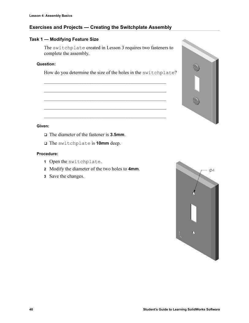
Task 1 — Modifying Feature Size
The switchplate created in Lesson 3 requires two fasteners to complete the assembly.
Question:
How do you determine the size of the holes in the switchplate?
__________________________________________________
__________________________________________________
__________________________________________________
__________________________________________________
__________________________________________________
Given:
� The diameter of the fastener is 3.5mm.
� The switchplate is 10mm deep.
Procedure:
1 Open the switchplate.
2 Modify the diameter of the two holes to 4mm.
3 Save the changes.
Lesson 4: Assembly Basics
Student’s Guide to Learning SolidWorks Software 41
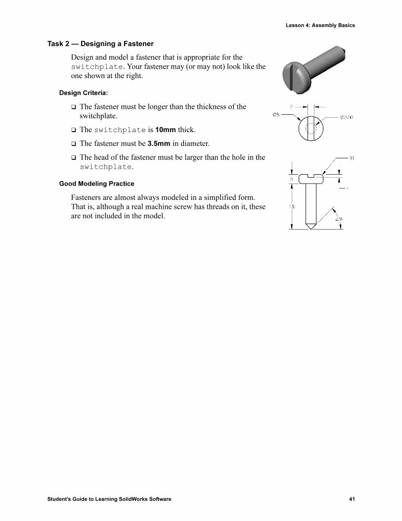
Task 2 — Designing a Fastener
Design and model a fastener that is appropriate for the switchplate. Your fastener may (or may not) look like the one shown at the right.
Design Criteria:
� The fastener must be longer than the thickness of the switchplate.
� The switchplate is 10mm thick.
� The fastener must be 3.5mm in diameter.
� The head of the fastener must be larger than the hole in the switchplate.
Good Modeling Practice
Fasteners are almost always modeled in a simplified form. That is, although a real machine screw has threads on it, these are not included in the model.

Lesson 4: Assembly Basics
42 Student’s Guide to Learning SolidWorks Software
Task 3 — Creating an Assembly
Create the switchplate-fastener assembly.
Procedure:
1 Create a new assembly.
The fixed component is the switchplate.
2 Drag the switchplate into the assembly window.
3 Drag the fastener into the assembly window.
The switchplate-fastener assembly requires three mates to fully define the assembly.
1 Create a Concentric mate between the cylindrical face of the fastener and the cylindrical face of the hole in the switchplate.
2 Create a Coincident mate between the back flat face of the fastener and the flat front face of the switchplate.
3 Create a Parallel mate between one of the flat faces on the slot of the fastener and the flat top face of the switchplate.
Note: If the necessary faces do not exist in the fastener or the switchplate, create the parallel mate using the appropriate reference planes in each component.
Faces
Faces
Faces

Lesson 4: Assembly Basics
Student’s Guide to Learning SolidWorks Software 43
4 Add a second instance of the fastener to the assembly.
You can add components to an assembly by dragging and dropping:
• Hold the Ctrl key, and then drag the component either from the FeatureManager design tree, or from the graphics area.
• The pointer changes to .
• Drop the component in the graphics area by releasing the left mouse button and the Ctrl key.
5 Add three mates to fully define the second fastener to the switchplate-fastener assembly.
6 Save the switchplate-fastener assembly.

Lesson 4: Assembly Basics
44 Student’s Guide to Learning SolidWorks Software
Exercises and Project — Creating CD Storage Box Assembly
Assemble the cdcase and storagebox that you created in Lesson 3.
Procedure:
1 Create a new assembly.
The fixed component is the storagebox.
2 Drag the storagebox into the assembly window.
3 Drag the cdcase into the assembly window to the right of the storagebox.
4 Create a Coincident mate between the bottom face of the cdcase and the inside bottom face of the storagebox.
5 Create a Coincident mate between the back face of the cdcase and the inside back face of the storagebox.
Faces
Faces
Inside back face

Lesson 4: Assembly Basics
Student’s Guide to Learning SolidWorks Software 45
6 Create a Distance mate between the left face of the cdcase and the inside left face of the storagebox.
Enter 1cm for Distance.
7 Save the assembly.
Enter cdcase-storagebox for the filename.
Component Patterns
Create a linear pattern of the cdcase component in the assembly.
The cdcase is the seed component. The seed component is what gets copied in the pattern.
1 Click Insert, Component Pattern, Linear Pattern.
The Linear Pattern PropertyManager appears.
2 Define the direction for the pattern.Click inside the Pattern Direction text box to make it active.Click the bottom horizontal front edge of the storagebox.
3 Observe the direction arrow.
The preview arrow should point to the right. If itdoes not, click the Reverse Direction button.
Faces

Lesson 4: Assembly Basics
46 Student’s Guide to Learning SolidWorks Software
4 Enter 1 cm for Spacing. Enter 25 for Instances.
5 Select the component to be patterned.
Make sure the Component to Pattern field is active, and then select the cdcase component from the FeatureManager design tree or the graphics area.Click OK.The Local Component Pattern feature is added to the FeatureManager design tree.
6 Save the assembly.
Click Save. Use the name cdcase-storagebox.

Lesson 4: Assembly Basics
Student’s Guide to Learning SolidWorks Software 47
Exercises and Projects — Assembling a Mechanical Claw
Assemble the claw mechanism shown at the right. This assembly will be used later, in Lesson 11, to create a movie using the SolidWorks Animator software.
Procedure:
1 Create a new assembly.
2 Save the assembly. Name it Claw-Mechanism.
3 Insert the Center-Post component into the assembly.The files for this exercises are found in the Claw folder in the Lesson04 folder.
4 Open the Collar part.
Arrange the windows as shown below.

Lesson 4: Assembly Basics
48 Student’s Guide to Learning SolidWorks Software
SmartMates
You can create some types of mating relationships automatically. Mates created with these methods are referred to as SmartMates.
You can create mates when you drag the part in specific ways from an open part window. The entity that you use to drag determines the types of mates that are added.
5 Select the cylindrical face of the Collar, and drag the Collar into the assembly. Point at the cylindrical face of the Center-Post in the assembly window.
When the pointer is over the Center-Post, the pointer changes to . This pointer indicates that a Concentric mate will result if the Collar is dropped at this location. A preview of the Collar snaps into place.
6 Drop the Collar.
A Concentric mate is added automatically.
Click Add/Finish Mate .
7 Close the Collar part document.

Lesson 4: Assembly Basics
Student’s Guide to Learning SolidWorks Software 49
8 Open the Claw.
Arrange the windows as shown below.
9 Add the Claw to the assembly using SmartMates
• Select the edge of the hole in the Claw.
It is important to select the edge and not the cylindrical face. This is because this type of SmartMate will add two mates:
• A Concentric mate between the cylindrical faces of the two holes.
• A Coincident mate between the planar face of the Claw and the arm of the Center-Post.

Lesson 4: Assembly Basics
50 Student’s Guide to Learning SolidWorks Software
10 Drag and drop the Claw onto the edge of the hole in the arm.
The pointer looks like this indicating that a Concentric and a Coincident mate will be added automatically. This SmartMate technique is ideal for putting fasteners into holes.
11 Close the Claw part document.
12 Drag the Claw as shown below. This makes it easier to select an edge in the next step.
13 Add the Connecting-Rod to the assembly.
Use the same SmartMate technique you used in steps 9 and 10 to mate one end of the Connecting-Rod to the end of the Claw.
There should be two mates:
• Concentric between the cylindrical faces of the two holes.
• Coincident between the planar faces of the Connecting-Rod and the Claw.
14 Mate the Connecting-Rod to the Collar.
Add a Concentric mate between the hole in the Connecting-Rod and the hole in the Collar.
Do not add a Coincident mate between the Connecting-Rod and the Collar.

Lesson 4: Assembly Basics
Student’s Guide to Learning SolidWorks Software 51
15 Add the pins.
There are three different length pins:
• Pin-Long (1.745 cm)
• Pin-Medium (1.295 cm)
• Pin-Short (1.245 cm)
Use Tools, Measure to determine which pin goes in which hole.
Add the pins using SmartMates.
Circular Component Pattern
Create a circular pattern of the Claw, Connecting-Rod, and pins.
1 Click Insert, Component Pattern, Circular Pattern.
The Circular Pattern PropertyManager appears.
2 Select the components to be patterned.
Make sure the Components to Pattern field is active, and then select the Claw, the Connecting-Rod, and the three pins.
3 Click View, Temporary Axes.
4 Click in the Pattern Axis field. Select the axis that runs down the center of the Center-Post for the center of rotation for the pattern.
5 Set the Angle to 120°.
6 Set the Instances to 3.
7 Click OK.
8 Turn off the temporary axes.
Dynamic Assembly Motion
Moving under defined components simulates movement of a mechanism through dynamic assembly motion.
9 Drag the Collar up and down while observing the motion of the assembly.
10 Save and close the assembly.
??
??
??

Lesson 4: Assembly Basics
52 Student’s Guide to Learning SolidWorks Software
Lesson 4 Vocabulary Worksheet
Name: _______________________________Class: _________ Date:_______________
Fill in the blanks with the words that are defined by the clues.
1 ____________________ copies one or more curves into the active sketch by projecting them onto the sketch plane.
2 In an assembly, parts are referred to as: ______________________________________
3 Relationships that align and fit components together in an assembly:_______________
4 The symbol (f) in the FeatureManager design tree indicates a component is: _______
_____________________________________________________________________
5 The symbol (-) indicates a component is: __________________________________
6 When you make a component pattern, the component you are copying is called the __________________ component.
7 A SolidWorks document that contains two or more parts:________________________
8 You cannot move or rotate a fixed component unless you _________________ it first.

Lesson 4: Assembly Basics
Student’s Guide to Learning SolidWorks Software 53
Lesson Summary
� An assembly contains two or more parts.
� In an assembly, parts are referred to as components.
� Mates are relationships that align and fit components together in an assembly.
� Components and their assembly are directly related through file linking.
� Changes in the components affect the assembly and changes in the assembly affect the components.
� The first component placed into an assembly is fixed.
� Under defined components can be moved using dynamic assembly motion. This simulates the movement of mechanisms.

Lesson 4: Assembly Basics
54 Student’s Guide to Learning SolidWorks Software

Student’s Guide to Learning SolidWorks Software 55
5
Lesson 5: SolidWorks Toolbox Basics
Goals of This Lesson
� Place standard SolidWorks Toolbox parts in assemblies.
� Modify Toolbox part definitions to customize standard Toolbox parts.
Before Beginning This Lesson
� Complete Lesson 4: Assembly Basics.
� Verify that SolidWorks Toolbox and SolidWorks
Toolbox Browser are set up and running on your classroom/lab computers. Click Tools, Add-Ins to activate these add-ins. SolidWorks Toolbox and SolidWorks Toolbox Browser are SolidWorks add-ins which are not loaded automatically. These add-ins must be specifically added during installation.
Resources for This Lesson
This lesson plan corresponds to Productivity Enhancements: Toolbox in the SolidWorks Tutorials.
SolidWorks Toolbox contains 1000's of library parts including fasteners, bearings, and structural members.

Lesson 5: SolidWorks Toolbox Basics
56 Student’s Guide to Learning SolidWorks Software
Competencies for Lesson 5
You develop the following competencies in this lesson:
� Engineering: Select fasteners automatically based on hole diameter and depth. Utilize fastener vocabulary such as thread length, screw size, and diameter.
� Technology: Utilize the Toolbox Browser and display of thread style.
� Math: Relate diameter of screw to screw size.
� Science: Explore fasteners created from different materials.
Active Learning Exercises — Adding Toolbox Parts
Follow the instructions in Productivity Enhancements: Toolbox in the SolidWorks Tutorials. Then proceed with the exercise below.
Add screws to the switchplate using the predefined hardware in Toolbox.
In the previous lesson, you added screws to the switchplate by modeling the screws and mating them to the switchplate in an assembly. As a general rule, hardware — such as screws — are standard components. Toolbox gives you the ability to apply standard hardware to assemblies without having to model it first.
Open the Switchplate Toolbox Assembly
Open the Switchplate Toolbox Assembly.
Notice that this assembly only has one part — or component — in it. Switchplate is the only part in the assembly.
An assembly is where you combine parts together. In this case, you are adding the screws to the switchplate.

Lesson 5: SolidWorks Toolbox Basics
Student’s Guide to Learning SolidWorks Software 57
Open Toolbox Browser
Expand the Toolbox item on the Design Library Task Pane. The Toolbox Browser appears.
The Toolbox Browser is an extension of the Design Library that contains all available Toolbox parts.
The Toolbox Browser is organized like a standard Windows Explorer folder view.
Selecting the Appropriate Hardware
Toolbox contains a wide variety of hardware. Selecting the right hardware is often critical to the success of a model.
You must determine the size of the holes before selecting the hardware to use and match the hardware to the hole.
1 Click Smart Dimension on the Dimensions/Relations toolbar or Measure on the Tools toolbar and select one of the holes on the switchplate to determine the hole size.
Note: The dimensions in this lesson are shown in inches.

Lesson 5: SolidWorks Toolbox Basics
58 Student’s Guide to Learning SolidWorks Software
2 In the Toolbox Browser, browse to Ansi Inch, Bolts and
Screws, Machine Screws in the folder structure.
The valid types of machine screws display.
3 Click and hold Pan Cross Head.
Does this hardware selection make sense for this assembly? The switchplate was designed with the size of the fasteners in mind. The holes in the switchplate are specifically designed for a standard fastener size.
The fastener size is not the only consideration in selecting a part. The type of fastener is important too. For example, you would not use miniature screws or square head bolts for the switchplate. They are the wrong size. They would be either too small or too large. You also have to take into consideration the user of this product. This switchplate has to be attachable with the most common of household tools.
Placing Hardware
1 Drag the screw towards the switchplate.
As you begin to drag the screw, it may appear very large.
Note: Drag and drop parts by holding the left mouse button. Release the mouse button when the part is correctly oriented.

Lesson 5: SolidWorks Toolbox Basics
Student’s Guide to Learning SolidWorks Software 59
2 Slowly drag the screw towards one of the switchplate holes until the screw snaps into the hole.
When the screw snaps into the hole, it is correctly oriented and properly mates with the surfaces of the part that it is combined with.
The screw still may appear too large for the hole.
3 When the screw is in the correct position, release the mouse button.
Specifying the Properties of the Toolbox Part
After you release the mouse button, a PropertyManager appears.
1 If necessary, change the properties of the screw to match the holes. In this case, a #6-32 screw with 1” length works with these holes.
2 When you have completed the property changes, click OK .
The first screw is now placed in the first hole.
Lesson 5: SolidWorks Toolbox Basics
60 Student’s Guide to Learning SolidWorks Software
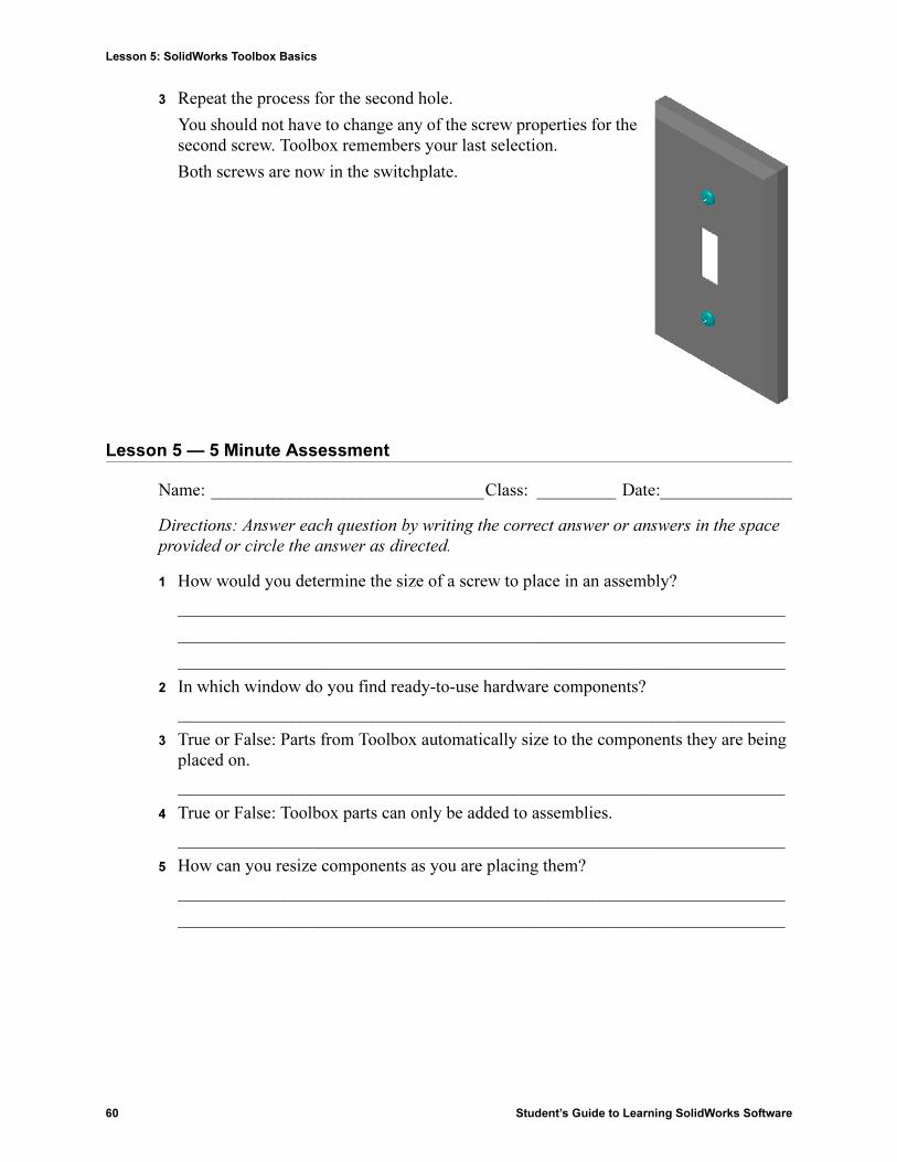
3 Repeat the process for the second hole.
You should not have to change any of the screw properties for the second screw. Toolbox remembers your last selection.
Both screws are now in the switchplate.
Lesson 5 — 5 Minute Assessment
Name: _______________________________Class: _________ Date:_______________
Directions: Answer each question by writing the correct answer or answers in the space
provided or circle the answer as directed.
1 How would you determine the size of a screw to place in an assembly?
_____________________________________________________________________
_____________________________________________________________________
_____________________________________________________________________
2 In which window do you find ready-to-use hardware components?
_____________________________________________________________________
3 True or False: Parts from Toolbox automatically size to the components they are being placed on.
_____________________________________________________________________
4 True or False: Toolbox parts can only be added to assemblies.
_____________________________________________________________________
5 How can you resize components as you are placing them?
_____________________________________________________________________
_____________________________________________________________________

Lesson 5: SolidWorks Toolbox Basics
Student’s Guide to Learning SolidWorks Software 61
Exercises and Projects — Bearing Block Assembly
Add bolts and washers to fasten the bearing rest to the bearing block.
Opening the Assembly
1 Open Bearing Block Assembly.
Bearing Block Assembly has Bearing Rest and Bearing Block as components.
In this exercise, you are going to bolt the bearing rest to the bearing block. The through holes in the bearing rest are designed to allow the bolts to pass through but not be loose. The holes in the bearing block are tapped holes. Tapped holes are threaded and specifically designed to act like nuts do. In other words, the bolt screws directly into the bearing block.
If you take a close look at the holes, you see that the holes in the bearing rest are larger than those of the bearing block. That is because the holes in the bearing block are represented with the amount of material needed for the creation of the screw threads. The screw threads are not visible. Threads are rarely shown in models.
Placing Washers
Washers have to be placed before the screws or bolts. You do not have to use washers every time you place screws. However, when you do intend to use washers, they must be placed before screws, bolts, or nuts so that the correct relationships can be established.
The washers mate with the surface of the part and the screw or bolt mates with the washer. Nuts also mate with washers.
2 Expand the Toolbox Browser icon in the Design Library Task Pane.

Lesson 5: SolidWorks Toolbox Basics
62 Student’s Guide to Learning SolidWorks Software
3 In the Toolbox Browser, browse for Ansi Inch, Washers, Plain Washers (Type A).
The valid types of Type A Washers display.
4 Click and hold Preferred - Narrow Flat Washer Type A washer.
5 Slowly drag the washer towards one of the bearing rest through holes until the washer seems to snap onto the hole.
When the washer snaps onto the hole, it is correctly oriented and properly mates with the surfaces of the part that it is combined with.
The washer still may appear too large for the hole.
6 When the washer is in the correct position, release the mouse button.
After you release the mouse button, a pop-up window appears. This window enables you to edit the properties of the washer.
7 Edit the washer properties for a 3/8th hole and click OK.
The washer is placed.
Notice that the inside diameter is slightly larger than 3/8th. In general, the size of the washer indicates the size of the bolt or screw that must pass through it — not the actual size of the washer.
8 Place a washer on the other hole.
9 Close the Insert Components PropertyManager
Lesson 5: SolidWorks Toolbox Basics
Student’s Guide to Learning SolidWorks Software 63
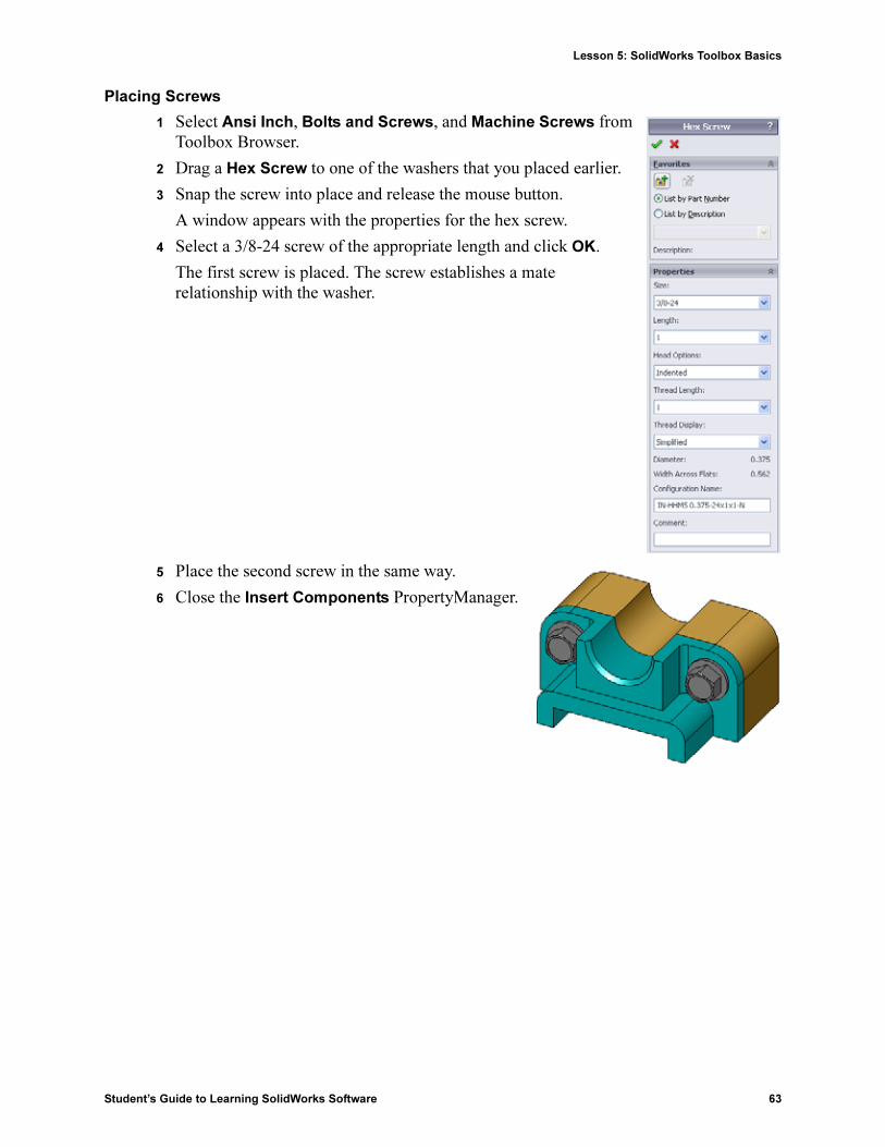
Placing Screws
1 Select Ansi Inch, Bolts and Screws, and Machine Screws from Toolbox Browser.
2 Drag a Hex Screw to one of the washers that you placed earlier.
3 Snap the screw into place and release the mouse button.
A window appears with the properties for the hex screw.
4 Select a 3/8-24 screw of the appropriate length and click OK.
The first screw is placed. The screw establishes a mate relationship with the washer.
5 Place the second screw in the same way.
6 Close the Insert Components PropertyManager.

Lesson 5: SolidWorks Toolbox Basics
64 Student’s Guide to Learning SolidWorks Software
Thread Display
While fasteners such as bolts and screws are fairly detailed parts, they also very common ones. In general, bolts and screws are not the parts that you design. Instead you will use off-the-shelf hardware components. It is a well-established design practice to not draw all of the details of fasteners, but to specify their properties and show only an outline — or simplified — view of them.
The three display modes for bolts and screws are:
� Simplified — Represents the hardware with few details. This is the most common display. Simplified display shows the bolt or screw as if it were unthreaded.
� Cosmetic — Represents some details of the hardware. Cosmetic display shows the barrel of the bolt or screw and represents the size of the threads as dashed lines.
� Schematic — Very detailed display which is rarely used. Schematic shows the bolt or screw as it really appears. This display is best used when designing a unique fastener or when specifying an uncommon one.
Making Sure That the Screws Fit
Before you placed the washers and screws, you should have measured the depth of the holes and the thickness of the washer as well as the diameter of the holes.
Even if you measured before placing the hardware, it is a good practice to verify that the screw fits as you intended it to. Viewing the assembly in wireframe, viewing it from different angles, using Measure, or creating a section view are some ways to do this.
A section view lets you look at the assembly as if you took a saw and cut it open.
1 Click Section View on the View toolbar.
The Section View PropertyManager appears.
2 Select Right as the Reference Section Plane.
3 Specify 3.4175 as the Offset Distance.
4 Click OK.
Now you see the cut away of the assembly right down the center of one of the screws. Is the screw long enough? Is it too long?
5 Click Section View again to turn off of the section view.

Lesson 5: SolidWorks Toolbox Basics
Student’s Guide to Learning SolidWorks Software 65
Modifying Toolbox Parts
If the screws — or other parts placed from Toolbox — are not the correct size you can modify their properties.
1 Select the part to modify, right-click, and select Edit Toolbox Definition.
A PropertyManager appears with the name of the Toolbox part. It is the window that you used to specify the properties of Toolbox parts as you were placing them.
2 Modify the part properties and click OK.
The Toolbox part changes.
More to Explore — Add Hardware to an Assembly
In the previous exercise you used Toolbox to add washers and screws to an assembly. In that assembly, the screws went into blind holes. In this exercise, add washers, lock washers, screws, and nuts to an assembly.
1 Open Bearing Plate Assembly.
2 Add the washers (Preferred - Narrow Flat
Washer Type A parts) to the through holes on the bearing rest first. The holes are 3/8th diameter.
3 Add the lock washers (Regular Spring Lock Washer parts) to the far side of the plate next.
4 Add 1-inch machine screws with a pan cross head. Snap these to the washers on the bearing rest.
5 Add hex nuts (Hex Nut parts). Snap these to the lock washers.
6 Use the techniques that you have learned to verify that the hardware is the correct size for this assembly.
Note: After modifying parts, you should rebuild the assembly.

Lesson 5: SolidWorks Toolbox Basics
66 Student’s Guide to Learning SolidWorks Software
Lesson 5 Vocabulary Worksheet
Name: _______________________________Class: _________ Date:_______________
Fill in the blanks with the words that are defined by the clues.
1 View that lets you look at the assembly as if you took a saw and cut it open:_________
_____________________________________________________________________
2 Type of hole that allows a screw or bolt to be screwed directly into it: ______________
_____________________________________________________________________
3 Common design practice that represents the screws and bolts showing outlines and few details:________________________________________________________________
4 Method for moving a Toolbox part from the Toolbox Browser to the assembly: ______
_____________________________________________________________________
5 Area of Design Library Task Pane that contains all available Toolbox parts: _________
_____________________________________________________________________
6 A file where you where you combine parts together:____________________________
7 Hardware — such as screws, nuts, washers, and lock washers — that you can select from the Toolbox Browser: _______________________________________________
8 Type of hole that allows a screw or bolt into it, but is not tapped:__________________
_____________________________________________________________________
9 Properties — such as size, length, thread length, display type — that describe a Toolbox part:__________________________________________________________________
Lesson 5: SolidWorks Toolbox Basics
Student’s Guide to Learning SolidWorks Software 67
Lesson Summary
� Toolbox provides ready-to-use parts — such as bolts and screws.
� Toolbox parts are placed by dragging and dropping them in assemblies.
� You can edit the property definitions of Toolbox parts.
� Holes created with the hole wizard are easy to match with properly-sized hardware from Toolbox.

Lesson 5: SolidWorks Toolbox Basics
68 Student’s Guide to Learning SolidWorks Software

Student’s Guide to Learning SolidWorks Software 69
6
Lesson 6: Drawing Basics
Goals of This Lesson
� Understand basic drawing concepts.
� Create detailed drawings of parts and assemblies.
Before Beginning This Lesson
� Create Tutor1 part from Lesson 3: The 40-Minute Running Start.
� Create Tutor2 part and the Tutor assembly from Lesson 4: Assembly Basics.
Drawing skills are required by industry. Review industry examples, case studies and white papers at www.solidworks.com.

Lesson 6: Drawing Basics
70 Student’s Guide to Learning SolidWorks Software
Resources for This Lesson
This lesson plan corresponds to Getting Started: Lesson 3 – Drawings in the SolidWorks Tutorials.
Additional information about drawings can be found in the Working with Models:
Advanced Drawings lesson in the SolidWorks Tutorials.
Competencies for Lesson 6
You develop the following competencies in this lesson:
� Engineering: Apply engineering drawing standards to part and assembly drawings. Apply concepts of orthographic projection to 2D standard views and isometric views.
� Technology: Explore associativity between different, but related file formats that change during the design process.
� Math: Explore how numeric values describe overall size and features of a part.
� A gap must exist between the profile lines and the extension lines.
� The size and style of leader line, text, and arrows should be consistent throughout the drawing.
Active Learning Exercises — Creating Drawings
Follow the instructions in Getting Started: Lesson 3 – Drawings in the SolidWorks Tutorials. In this lesson you will create two drawings. First, you will create the drawing for the part named Tutor1 which you built in a previous lesson. Then you will create an assembly drawing of the Tutor assembly.

Lesson 6: Drawing Basics
Student’s Guide to Learning SolidWorks Software 71
Lesson 6 — 5 Minute Assessment
Name: _______________________________Class: _________ Date:_______________
Directions: Answer each question by writing the correct answer or answers in the space
provided or circle the answer as directed.
1 How do you open a drawing template?
_____________________________________________________________________
2 What is the difference between Edit Sheet Format and Edit Sheet?
_____________________________________________________________________
_____________________________________________________________________
_____________________________________________________________________
3 A title block contains information about the part and/or assembly. Name five pieces of information that can be contained in a title block.
_____________________________________________________________________
_____________________________________________________________________
_____________________________________________________________________
4 True or False. Right-click Edit Sheet Format to modify title block information.
_____________________________________________________________________
5 What three views are inserted into a drawing when you click Standard 3 View?
_____________________________________________________________________
6 How do you move a drawing view?
_____________________________________________________________________
7 What command is used to import part dimensions into the drawing?
_____________________________________________________________________
8 True or False. Dimensions must be clearly positioned on the drawing.
_____________________________________________________________________
9 Give four rules for good dimensioning practice.
_____________________________________________________________________
_____________________________________________________________________
_____________________________________________________________________
_____________________________________________________________________

Lesson 6: Drawing Basics
72 Student’s Guide to Learning SolidWorks Software
Exercises and Projects — Creating a Drawing
Task 1 — Create a Drawing Template
Create a new A-size ANSI standard drawing template.
For Units use millimeters.
Name the template ANSI-MM-SIZEA.
Procedure:
1 Create a new drawing using the Tutorial drawing template.
This is an A-size sheet that uses the ISO drafting standard.
2 Click Tools, Options and then click the Document Properties tab.
3 Set the Overall drafting standard to ANSI.
4 Make any other desired changes to the document properties, such as the dimension text font and size.
5 Click Units and verify that the Length units are set to millimeters.
6 Click OK to apply the changes and close the dialog.
7 Click File, Save As...
8 From the Save as type: list, click Drawing Templates (*.drwdot).
The system automatically jumps to the directory where the templates are installed.
9 Click to create a new folder.
10 Name the new folder Custom.
11 Browse to the Custom folder.
12 Enter ANSI-MM-SIZEA for the name.
13 Click Save.
Drawing templates have the suffix *.drwdot

Lesson 6: Drawing Basics
Student’s Guide to Learning SolidWorks Software 73
Task 2 — Create a Drawing for Tutor2
1 Create a drawing for Tutor2. Use the drawing template you created in Task 1.
Review the guidelines for determining which views are necessary. Since Tutor2 is square, the top and right views communicate the same information. Only two views are necessary to fully describe the shape of Tutor2.
2 Create Front and Top views. Add an Isometric view.
3 Import the dimensions from the part.
4 Create a note on the drawing to label the wall thickness.
Click Insert, Annotations, Note. Enter WALL THICKNESS = 4mm.

Lesson 6: Drawing Basics
74 Student’s Guide to Learning SolidWorks Software
Task 3 — Add a Sheet to an Existing Drawing
1 Add a new sheet to the existing drawing you created in Task 2. Use the drawing template you created in Task 1.
2 Create three standard views for the storagebox.
3 Import the dimensions from the model.
4 Create an Isometric view in a drawing for the storagebox.

Lesson 6: Drawing Basics
Student’s Guide to Learning SolidWorks Software 75
Task 4 — Add a Sheet to an Existing Assembly Drawing
1 Add a new sheet to the existing drawing you created in Task 2. Use the drawing template you created in Task 1.
2 Create an Isometric view in a drawing for the cdcase-storagebox assembly.

Lesson 6: Drawing Basics
76 Student’s Guide to Learning SolidWorks Software
More to Explore — Create a Parametric Note
Investigate the on-line documentation to learn how to create a parametric note. In a parametric note, text, such as the numeric value of the wall thickness, is replaced with a dimension. This causes the note to update whenever the thickness of the shell is changed.
Once a dimension is linked to a parametric note, the dimension should not be deleted. That would break the link. However, the dimension can be hidden by right-clicking the dimension, and selecting Hide from the shortcut menu.
Procedure:
1 Import the model dimensions into the drawing.
When you import the dimensions from the model, the 4mm thickness dimension of the Shell feature will also be imported. This dimension is needed for the parametric note.
2 Click Note on the Annotations toolbar or Insert, Annotations, Note.
3 Click to place the note on the drawing.
A text insertion box appears . Enter the note text. For example: WALL
THICKNESS =
4 Select the dimension of the Shell feature.
Instead of typing the value, click the dimension. The system will enter the dimension into the text note.
5 Type the rest of the note.
Make sure the text insertion cursor is at the end of the text string and type mm.
6 Click OK to close the Note PropertyManager.
Position the note on the drawing by dragging it.
7 Hide the dimension.
Right-click the dimension, and select Hide from the shortcut menu.

Lesson 6: Drawing Basics
Student’s Guide to Learning SolidWorks Software 77
More to Explore — Add a Sheet to Switchplate Drawing
1 Add a new sheet to the existing drawing you created in Task 2. Use the drawing template you created in Task 1.
2 Create a drawing of the switchplate.
The chamfer is too small to be clearly seen and dimensioned in either the Top or Right views. A detail view is required. Detail views are views that usually show only a portion of the model, at a larger scale. To make a detail view:
3 Select the view from which the detail view will be derived.
4 Click Detail View on the Drawing toolbar, or Insert, Drawing View, Detail.
This turns on the Circle sketch tool.
5 Sketch a circle around the area you want to show.
When you finish sketching the circle, a preview of the detail view appears.
6 Position the detail view on the drawing sheet.
The system automatically adds a label to the detail circle and the view itself. To change the scale of the detail view, edit the label’s text.
7 You can import dimensions directly into a detail view, or drag them from other views.

Lesson 6: Drawing Basics
78 Student’s Guide to Learning SolidWorks Software
Lesson Summary
� Engineering Drawings communicate three things about the objects they represent:
• Shape – Views communicate the shape of an object.
• Size – Dimensions communicate the size of an object.
• Other information – Notes communicate non-graphic information about manufacturing processes such as drill, ream, bore, paint, plate, grind, heat treat, remove burrs, and so forth.
� The general characteristics of an object will determine what views are required to describe its shape.
� Most objects can be described using three properly selected views.
� There are two kinds of dimensions:
• Size dimensions – how big is the feature?
• Location dimensions – where is the feature?
� A drawing template specifies:
• Sheet (paper) size
• Orientation - Landscape or Portrait
• Sheet Format

Student’s Guide to Learning SolidWorks Software 79
7
Lesson 7: SolidWorks eDrawings Basics
Goals of This Lesson
� Create eDrawings® files from existing SolidWorks files.
� View and manipulate eDrawings.
� Email eDrawings.
Before Beginning This Lesson
� Complete Lesson 6: Drawing Basics.
� An email application has to be loaded on the student’s computer. If email is not present on the student’s computer, you will not be able to complete More to Explore- Emailing
an eDrawings File.
� Verify that eDrawings is set up and running on your classroom/lab computers. eDrawings is a SolidWorks add-in which is not loaded automatically. This add-in must be specifically added during installation.
Resources for This Lesson
This lesson plan corresponds to Working with Models: SolidWorks eDrawings in the SolidWorks Tutorials.
Competencies for Lesson 7
You develop the following competencies in this lesson:
� Engineering: Mark up engineering drawings utilizing eDrawings comments. Understand how to communicate with manufacturing vendors.
� Technology: Work with different file formats including animations. Understand attachments for email.
Save paper. To send projects to your instructor or friends, use eDrawings and email.

Lesson 7: SolidWorks eDrawings Basics
80 Student’s Guide to Learning SolidWorks Software
Active Learning Exercises — Creating an eDrawings File
Follow the instructions in Working with Models: SolidWorks eDrawings in the SolidWorks Tutorials. Then proceed with the exercises below.
Create and explore an eDrawings file of the switchplate part created earlier.
Creating an eDrawings File
1 In SolidWorks, open the switchplate part.
2 Click Publish an eDrawing on the eDrawings toolbar to publish an eDrawing of the part.
The eDrawing of switchplate appears in the eDrawings Viewer.
Note: You created switchplate during Lesson 2.
Note: You can create eDrawings from AutoCAD® drawings too. Refer to the topic Creating SolidWorks eDrawing Files in the eDrawings online help for more information.

Lesson 7: SolidWorks eDrawings Basics
Student’s Guide to Learning SolidWorks Software 81
Viewing an Animated eDrawings File
Animation enables you to dynamically view eDrawings.
1 Click Next .
The view changes to the Front view. You can click Next repeatedly to step through the views.
2 Click Previous .
The previous view is displayed.
3 Click Continuous Play .
Each view is displayed one by one in a continuous display.
4 Click Stop .
The continuous display of views halts.
5 Click Home .
The default or home view is displayed.
Viewing Shaded and Wireframe eDrawings Files
1 Click Shaded .
The display of the switch plate changes from shaded to wireframe.
2 Click Shaded again.
The display of the switch plate changes from wireframe to shaded.
Saving an eDrawings File
1 In the eDrawings Viewer click File, Save As.
2 Select Enable measure.
This option enables anyone viewing the eDrawing file to measure the geometry. This is called making the file “review-enabled”.
3 Select eDrawings Zip Files
(*.zip) from the Save as type: dropdown list.
This option saves the file as an eDrawings Zip file, which contains the eDrawings Viewer and the active eDrawings file.
4 Click Save.

Lesson 7: SolidWorks eDrawings Basics
82 Student’s Guide to Learning SolidWorks Software
Markup and Measure
You can markup eDrawings with tools from the Markup toolbar. Measure, if enabled (set at the time of eDrawing save in the save options dialog) allows for rudimentary dimension checking.
For tracking purposes markup comments appear as discussion threads on the Markup tab of the eDrawing Manager. In this example you will add a cloud with text and a leader.
1 Click Cloud with Leader on the Markup toolbar.
Move the cursor into the graphics area. The pointer changes to .
2 Click the front face of the switchplate.
This is where the leader will begin.
3 Move the pointer to where you want to place the text and then click. A text box appears.
4 In the text box, type the text you want to appear in the cloud and then click OK .
The cloud with text appears attached to the leader. If necessary, click Zoom to Fit .
5 Close the eDrawing file, saving your changes.

Lesson 7: SolidWorks eDrawings Basics
Student’s Guide to Learning SolidWorks Software 83
Lesson 7 — 5 Minute Assessment
Name: _______________________________Class: _________ Date:_______________
Directions: Answer each question by writing the correct answer or answers in the space
provided or circle the answer as directed.
1 How do you create an eDrawing?
_____________________________________________________________________
_____________________________________________________________________
_____________________________________________________________________
2 How do you send others eDrawings?
_____________________________________________________________________
3 What is the quickest way to return to the default view?
_____________________________________________________________________
4 True or False: You can make changes to a model in an eDrawing.
_____________________________________________________________________
_____________________________________________________________________
5 True or False: You need to have the SolidWorks application in order to view eDrawings.
_____________________________________________________________________
6 What eDrawings feature enables you to dynamically view parts, drawings, and assemblies?
_____________________________________________________________________

Lesson 7: SolidWorks eDrawings Basics
84 Student’s Guide to Learning SolidWorks Software
Exercises and Projects — Exploring eDrawings Files
In this exercise, you explore eDrawings created from SolidWorks parts, assemblies, and drawings.
eDrawings of Parts
1 In SolidWorks, open the Tutor1 part created in Lesson 3.
2 Click Publish an eDrawing .
An eDrawing of the part appears in the eDrawings Viewer.
3 Hold Shift and press one of the arrow keys.
The view of rotates 90° each time you press an arrow key.
4 Press an arrow key without holding Shift.
The view of rotates 15° each time you press an arrow key.
5 Click Home .
The default or home view is displayed.
6 Click Continuous Play .
Each view is displayed one by one in a continuous display. Observe this for a moment.
7 Click Stop .
The continuous display of views halts.
8 Close the eDrawing file without saving it.

Lesson 7: SolidWorks eDrawings Basics
Student’s Guide to Learning SolidWorks Software 85
eDrawings of Assemblies
1 In SolidWorks, open the Tutor assembly created in Lesson 4.
2 Click Publish an eDrawing .
An eDrawing of the assembly appears in the eDrawings Viewer.
3 Click Continuous Play .
Each view is displayed one by one. Observe this for a moment.
4 Click Stop .
The continuous display of views halts.
5 Click Home .
The default or home view is displayed.

Lesson 7: SolidWorks eDrawings Basics
86 Student’s Guide to Learning SolidWorks Software
6 In the Components panel, right-click Tutor1-1 and select Make Transparent from the shortcut menu.
The Tutor1-1 part become transparent so you can see through it.
7 Right-click Tutor1-1 and select Hide from the shortcut menu.
The Tutor1-1 part no longer displays in the eDrawing. This part still exists in the eDrawing, it is just hidden.
8 Right-click Tutor1-1 again and select Show.
The Tutor1-1 part displays.

Lesson 7: SolidWorks eDrawings Basics
Student’s Guide to Learning SolidWorks Software 87
eDrawings of Drawings
1 Open the drawing you created in Lesson 6. This drawing has two sheets. Sheet 1 shows the part Tutor1. Sheet 2 shows the Tutor assembly. An example of this is in the Lesson07 folder and is named Finished Drawing.slddrw.
2 Click Publish an eDrawing .
3 Select All sheets.
A window appears so you can select which sheets to include in the eDrawing.
Click OK.
An eDrawing of the drawing appears in the eDrawings Viewer.
4 Click Continuous Play .
Each view is displayed one by one. Observe this for a moment. Notice that the animation stepped through both sheets of the drawing.
5 Click Stop .
The continuous display of drawing views halts.
6 Click Home .
The default or home view is displayed.

Lesson 7: SolidWorks eDrawings Basics
88 Student’s Guide to Learning SolidWorks Software
Using the eDrawings Manager
You can use the eDrawings Manager, located on the left side of the eDrawings Viewer, to display tabs that let you manage file information. When you open a file, the most appropriate tab is automatically active. For example, when you open a drawing file, the Sheets tab is active.
The Sheets tab makes it easy to navigate through a multi-sheet drawing.
1 In the Sheets tab of the eDrawings Manager, double-click Sheet2.
Sheet2 of the drawing is displayed in the eDrawings Viewer. Use this method to navigate a multi-sheet drawing.
2 In the Sheets tab of the eDrawings Manager, right-click one of the drawing views.
The Hide/Show menu appears.
3 Click Hide.
Notice how the eDrawings file changes.
4 Return to Sheet1.
The 3D Pointer
You can use the 3D Pointer to point to a location in all of the drawing views in drawing files. When you use the 3D Pointer, linked crosshairs appear in each of the drawing views. For example, you can place the crosshairs on an edge in one view and the crosshairs in the other views point to the same edge.
Note: You can also switch between multiple sheets by clicking the tabs located below the graphics area.

Lesson 7: SolidWorks eDrawings Basics
Student’s Guide to Learning SolidWorks Software 89
The crosshairs colors indicate the following:
1 Click 3D Pointer .
The eDrawing of the drawing displays the 3D pointer. The 3D pointer helps you to see the orientation of each view.
2 Move the 3D Pointer.
Notice how the pointer moves in each view.
Overview Window
The Overview Window gives you a thumbnail view of the entire drawing sheet. This is especially handy when working with large, complicated drawings. You can use the window to navigate among the views. In the Overview Window, click the view you want to look at.
1 Click Overview Window .
The Overview Window appears.
2 Click the Front view in the Overview Window.
Notice how the eDrawings Viewer changes.
Color Axis
Red X-Axis (perpendicular to YZ plane)
Blue Y-Axis (perpendicular to XZ plane)
Green Z-Axis (perpendicular to XY plane)

Lesson 7: SolidWorks eDrawings Basics
90 Student’s Guide to Learning SolidWorks Software
More to Explore — Emailing an eDrawings File
If your system is set up with an email application, you can see how easy it is to send an eDrawing to someone else.
1 Open one of the eDrawings that you created earlier in this lesson.
2 Click Send .
The Send As menu appears.
3 Select the file type to send and click OK.
An email message is created with the file attached.
4 Specify an email address to send the message to.
5 Add text to the email message if you would like to.
6 Click Send.
The email is sent with the eDrawing attached. The person receiving it can view it, animate it, send it on to others, and so forth.

Lesson 7: SolidWorks eDrawings Basics
Student’s Guide to Learning SolidWorks Software 91
Lesson 7 Vocabulary Worksheet
Name: _______________________________Class: _________ Date:_______________
Fill in the blanks with the words that are defined by the clues.
1 The ability to dynamically view an eDrawing: ________________________________
2 Halting a continuous play of an eDrawing animation:___________________________
3 Command that enables you to step backwards one step at a time through an eDrawing animation:_____________________________________________________________
4 Non-stop replay of eDrawing animation:_____________________________________
5 Rendering of 3D parts with realistic colors and textures: ________________________
6 Go forward one step in an eDrawing animation: _______________________________
7 Command used to create an eDrawing: ______________________________________
8 Graphic aid that enables you to see the model orientation in an eDrawing created from a SolidWorks drawing: ____________________________________________________
9 Quickly return to the default view:__________________________________________
10 Command that enables you to use email to share eDrawings with others: ___________

Lesson 7: SolidWorks eDrawings Basics
92 Student’s Guide to Learning SolidWorks Software
Lesson Summary
� eDrawings can be created quickly from part, assembly, and drawing files.
� You can share eDrawings with others — even if they don’t have SolidWorks.
� Email is the easiest way to send an eDrawing to others.
� Animation enables you to see all views of a model.
� You can hide selected components of an assembly eDrawing and selected views of a drawing eDrawing.

Student’s Guide to Learning SolidWorks Software 93
8
Lesson 8: Design Tables
Goals of This Lesson
Create a design table that generates the following configurations of Tutor1.
Before Beginning This Lesson
Design Tables requires the Microsoft Excel® application. Ensure that Microsoft Excel is loaded on your classroom/lab systems.
Resources for This Lesson
This lesson plan corresponds to Productivity Enhancements: Design Tables in the SolidWorks Tutorials.
The SolidWorks Teacher Blog, http://blogs.solidworks.com/teacher, SolidWorks Forumshttp://forums.solidworks.com and SolidWorks Users Groups http://www.swugn.org provide a great resource to instructors and students.

Lesson 8: Design Tables
94 Student’s Guide to Learning SolidWorks Software
Competencies for Lesson 8
You develop the following competencies in this lesson:
� Engineering: Explore family of parts with a design table. Understand how design intent can be built into a part to allow for changes.
� Technology: Link an Excel spreadsheet with a part or an assembly. See how they relate a manufactured component.
� Math: Work with numerical values to change overall size and shape of a part and assembly. Develop width, height and depth values to determine volume of the CD Storage box modifications.
Active Learning Exercises — Creating a Design Table
Create the design table for Tutor1. Follow the instructions in Productivity
Enhancements: Design Tables in the SolidWorks Tutorials.

Lesson 8: Design Tables
Student’s Guide to Learning SolidWorks Software 95
Lesson 8 — 5 Minute Assessment
Name: _______________________________Class: _________ Date:_______________
Directions: Answer each question by writing the correct answer or answers in the space
provided or circle the answer as directed.
1 What is a configuration?
_____________________________________________________________________
2 What is a design table?
_____________________________________________________________________
_____________________________________________________________________
_____________________________________________________________________
3 What additional Microsoft software application is required to create design tables in SolidWorks?
_____________________________________________________________________
4 What are three key elements of a design table?
_____________________________________________________________________
_____________________________________________________________________
5 True or False. Link Values equates a dimension value to a shared variable name.
_____________________________________________________________________
6 Describe the advantage of using geometric relations versus linear dimensions to position the Knob feature on the Box feature.
_____________________________________________________________________
_____________________________________________________________________
_____________________________________________________________________
7 What is the advantage of creating a design table?
_____________________________________________________________________
_____________________________________________________________________

Lesson 8: Design Tables
96 Student’s Guide to Learning SolidWorks Software
Exercises and Projects — Creating a Design Table for Tutor2
Task 1 — Creating Four Configurations
Create a design table for Tutor2 that corresponds to the four configurations of Tutor3. Rename the features and the dimensions. Save the part as Tutor4.
Task 2 — Creating Three Configurations
Create three configurations of the storagebox to contain 50, 100 and 200 CDs. The maximum width dimension is 120cm.
100 CDs
200 CDs
50 CDs

Lesson 8: Design Tables
Student’s Guide to Learning SolidWorks Software 97
Task 3 — Modifying Configurations
Convert the overall dimensions of the 50 CD storagebox from centimeters to inches. The design for the CD storagebox was created overseas. The CD storagebox will be manufactured in the US.
Given:
� Conversion: 2.54cm = 1 inch
� Box_width = 54.0cm
� Box_height = 16.4cm
� Box_depth = 17.2cm
� Overall dimensions = box_width x box_height x box_depth
� Box_width = ______________________
� Box_height = ______________________
� Box_depth = ______________________
� Use SolidWorks to confirm the conversion values.
Task 4 — Determining Feasibility of Configurations
What CD storagebox configurations are feasible for use in your classroom?
___________________________________________________________
___________________________________________________________
___________________________________________________________
Exercises and Projects — Creating Part Configurations Using Design Tables
Create a cup. In the Extrude Feature dialog box, use a 5° Draft Angle. Create four configurations using a design table. Experiment with different dimensions.
??
??
??
Note: Units are in Inches

Lesson 8: Design Tables
98 Student’s Guide to Learning SolidWorks Software
More to Explore — Configurations, Assemblies, and Design Tables
When each component in an assembly has multiple configurations, it make sense that the assembly should have multiple configurations as well. There are two ways to accomplish this:
� Manually change the configuration being used by each component in the assembly.
� Create an assembly design table that specifies which configuration of each component is to be used for each version of the assembly.
Changing the Configuration of a Component in an Assembly
To manually change the displayed configuration of a component in an assembly:
1 Open the assembly Tutor Assembly which is located in the Lesson08 folder.
2 Right-click the component, either in the FeatureManager design tree or in the graphics area, and select Properties .
3 In the Component Properties dialog, select the desired configuration from the list in the Referenced configuration area.
Click OK.
4 Repeat this procedure for each component in the assembly.

Lesson 8: Design Tables
Student’s Guide to Learning SolidWorks Software 99
Assembly Design Tables
While manually changing the configuration of each component in an assembly works, it is neither efficient nor very flexible. Switching from one version of an assembly to another would be tedious. A better approach would be to create an assembly design table.
The procedure for creating an assembly design table is very similar to the procedure for creating a design table in an individual part. The most significant difference is the choice of different keywords for the column headers. The keyword we will explore here is $CONFIGURATION@component<instance>.
Procedure
1 Click Insert, Tables, Design Table.
The Design Table PropertyManager appears.
2 For Source, click Blank and then click OK .
3 The Add Rows and Columns dialog box appears.
If the assembly already contained configurations that were created manually they would be listed here. You could select them and they would automatically be added to the design table.
4 Click Cancel.
5 In cell B2, enter the keyword $Configuration@ followed by the name of the component and its instance number. In this example, the component is Tutor3 and the instance is <1>.
6 In cell C2, enter the keyword $Configuration@Tutor4<1>.

Lesson 8: Design Tables
100 Student’s Guide to Learning SolidWorks Software
7 Add the configuration names in column A.
8 Fill in the cells of col-umns B and C with the appropriate configura-tions for the two com-ponents.
9 Finish inserting the design table.
Click in the graphics area. The system reads the design table and generates the configurations.
Click OK to close the message dialog.
10 Switch to the ConfigurationManager.
Each of the configurations specified in the design table should be listed.
11 Test the configurations.
Double-click on each configuration to verify that they display correctly.
Note: The configuration names are listed in the ConfigurationManager alphabetically, not in the order in which they appeared in the design table.

Lesson 8: Design Tables
Student’s Guide to Learning SolidWorks Software 101
Lesson Summary
� Design Tables simplify making families of parts.
� Design Tables automatically change the dimensions and features of an existing part to create multiple configurations. The configurations control the size and shape of a part.
� Design Tables requires Microsoft Excel application.

Lesson 8: Design Tables
102 Student’s Guide to Learning SolidWorks Software

Student’s Guide to Learning SolidWorks Software 103
9
Lesson 9: Revolve and Sweep Features
Goals of This Lesson
Create and modify the following parts and assembly.
Resources for This Lesson
This lesson plan corresponds to Building Models: Revolves and Sweeps in the SolidWorks Tutorials.
The Certified SolidWorks Associate Exam (CSWA) proves to employers that students have the fundamental design competencies www.solidworks.com/cswa.

Lesson 9: Revolve and Sweep Features
104 Student’s Guide to Learning SolidWorks Software
Competencies for Lesson 9
You develop the following competencies in this lesson:
� Engineering: Explore different modeling techniques that are utilized for parts molded or machined in a lathe process. Modify the design to accept a candle of different sizes.
� Technology: Explore the difference in plastic design for cups and travel mugs.
� Math: Create axes and a profile of revolution to create a solid, 2D ellipse, and arcs.
� Science: Calculate the volume and unit conversion for a container.

Lesson 9: Revolve and Sweep Features
Student’s Guide to Learning SolidWorks Software 105
Active Learning Exercises — Creating a Candlestick
Create the candlestick. Follow the instructions in Building Models: Revolves and Sweeps in the SolidWorks Tutorials.
The part name is Cstick.sldprt. However, throughout this lesson, we will refer to it as “candlestick” because that makes more sense.
Lesson 9 — 5 Minute Assessment
Name: _______________________________Class: _________ Date:_______________
Directions: Answer each question by writing the correct answer or answers in the space
provided or circle the answer as directed.
1 What features did you use to create the candlestick?
_____________________________________________________________________
2 What special piece of sketch geometry is useful, but not required for a revolve feature?
_____________________________________________________________________
3 Unlike an extruded feature, a swept feature requires a minimum of two sketches. What are these two sketches?
_____________________________________________________________________
4 What information does the pointer provide while sketching an arc?
_____________________________________________________________________
_____________________________________________________________________
5 Examine the three illustrations at the right. Which one is not a valid sketch for a revolve feature?
Why?
___________________________
___________________________
___________________________
_____________________________________________________________________
_____________________________________________________________________
A B C

Lesson 9: Revolve and Sweep Features
106 Student’s Guide to Learning SolidWorks Software
Exercises and Projects — Creating a Candle to Fit the Candlestick
Task 1 — Revolve Feature
Design a candle to fit the candlestick.
� Use a revolve feature as the base feature.
� Taper the bottom of the candle to fit into the candlestick.
� Use a sweep feature for the wick.
Question:
What other features could you use to create the candle? Use a sketch to illustrate your answer if necessary.
_________________________________________________________________
_________________________________________________________________
_________________________________________________________________
_________________________________________________________________
_________________________________________________________________

Lesson 9: Revolve and Sweep Features
Student’s Guide to Learning SolidWorks Software 107
Task 2 — Create an Assembly
Create a candlestick assembly.
Task 3 — Create a Design Table
You work for a candle manufacturer. Use a design table to create 380 mm, 350 mm, 300 mm, and 250 mm candles.

Lesson 9: Revolve and Sweep Features
108 Student’s Guide to Learning SolidWorks Software
Exercises and Projects — Modify the Outlet Plate
Modify the outletplate that you created earlier in Lesson 2.
� Edit the sketch for the circular cuts that form the openings for the outlet. Create new cuts using the sketch tools. Apply what you have learned about Link Values and geometric relations to properly dimension and constrain the sketch.
� Add a swept boss feature to the back edge.
• The sweep section includes a 90° arc.
• The radius of the arc is equal to the length of the model edge as shown in the accompanying illustration.
• Use geometric relations to fully define the sweep section sketch.
• The sweep path is made up of the four rear edges of the part.
• Use Convert Entities to create the sweep path.
� The desired result is shown in the illustration at the right.
Path
Sweep Section

Lesson 9: Revolve and Sweep Features
Student’s Guide to Learning SolidWorks Software 109
More to Explore — Design and Model a Mug
Design and model a mug. This is a rather open-ended assignment. You have an opportunity to express your creativity and ingenuity. The design of a mug can vary from the simple to the complex. A couple of examples are shown at the right.
There are two specific requirements:
� Use a revolve feature for the body of the mug.
� Use a swept feature for the handle.
Task 4 — Determine Volume of Mug
How much coffee does the mug shown at the right hold?
Given:
� Inside Diameter = 2.50”
� Overall height of the mug = 3.75”
� Thickness of the bottom = 0.25”
� Coffee cups are not filled to the brim. Allow 0.5” space at the top.
_________________________________________________
_________________________________________________
_________________________________________________
Conversion:
A cup of coffee in the US is sold by the fluid ounce, not by the cubic inch. How many ounces does the mug hold?
Given:
1 gallon = 231 in3
128 ounces = 1 gallon
_________________________________________________
_________________________________________________
_________________________________________________
More complex design –a commuter’s spill-prooftravel mug
Simple design

Lesson 9: Revolve and Sweep Features
110 Student’s Guide to Learning SolidWorks Software
More to Explore — Use Revolve Feature to Design a Top
Use a revolve feature to create a toy top of your own design.
Lesson Summary
� A Revolve feature is created by rotating a 2D profile sketch around an axis of revolution.
� The profile sketch can use a sketch line (that is part of the profile) or a centerline as the axis of revolution.
� The profile sketch cannot cross the axis of revolution.
� The Sweep feature is created by moving a 2D profile along a path.
� The Sweep feature requires two sketches:
• Sweep Path
• Sweep Section
� Draft tapers the shape. Draft is important in molded, cast, or forged parts.
� Fillets are used to smooth edges.
Good Good No Good

Student’s Guide to Learning SolidWorks Software 111
10
Lesson 10: Loft Features
Goals of This Lesson
Create the following part.
Resources for This Lesson
This lesson plan corresponds to Building Models: Lofts in the SolidWorks Tutorials.
Additional SolidWorks tutorials provide knowledge into sheet metal, plastic and machine parts.
profiles
chisel
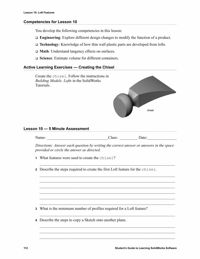
Lesson 10: Loft Features
112 Student’s Guide to Learning SolidWorks Software
Competencies for Lesson 10
You develop the following competencies in this lesson:
� Engineering: Explore different design changes to modify the function of a product.
� Technology: Knowledge of how thin wall plastic parts are developed from lofts.
� Math: Understand tangency effects on surfaces.
� Science: Estimate volume for different containers.
Active Learning Exercises — Creating the Chisel
Create the chisel. Follow the instructions in Building Models: Lofts in the SolidWorks Tutorials.
Lesson 10 — 5 Minute Assessment
Name: _______________________________Class: _________ Date:_______________
Directions: Answer each question by writing the correct answer or answers in the space
provided or circle the answer as directed.
1 What features were used to create the chisel?
_____________________________________________________________________
2 Describe the steps required to create the first Loft feature for the chisel.
_____________________________________________________________________
_____________________________________________________________________
_____________________________________________________________________
_____________________________________________________________________
_____________________________________________________________________
_____________________________________________________________________
3 What is the minimum number of profiles required for a Loft feature?
_____________________________________________________________________
4 Describe the steps to copy a Sketch onto another plane.
_____________________________________________________________________
_____________________________________________________________________
_____________________________________________________________________
chisel

Lesson 10: Loft Features
Student’s Guide to Learning SolidWorks Software 113
Exercises and Projects — Creating the Bottle
Create the bottle as shown in the drawing.
Note: All dimensions in the Bottle exercise are in millimeters.

Lesson 10: Loft Features
114 Student’s Guide to Learning SolidWorks Software
Exercises and Projects — Creating a Bottle with Elliptical Base
Create bottle2 with an elliptical extruded boss feature. The top of the bottle is circular. Design bottle2 with your own dimensions.
Exercises and Projects — Creating a Funnel
Create the funnel as shown in the drawing below.
� Use 1mm for the wall thickness.
bottle2

Lesson 10: Loft Features
Student’s Guide to Learning SolidWorks Software 115
Exercises and Projects — Creating a Screwdriver
Create the screwdriver.
� Use inches for the units.
� Create the handle as the first feature. Use a revolved feature.
� Create the shaft as the second feature. Use an extruded feature.
� The overall length of the blade (shaft and tip together) is 7 inches. The tip is 2
inches long. Compute the length of the shaft.
� Create the tip as the third feature. Use a loft feature.
� Create the sketch for the end of the tip first. This is a rectangle 0.50” by 0.10”.
� The middle — or second profile — is sketched using a 0.10” offset (to the outside) of the tip.
� The third profile is the circular face on the end of the shaft.
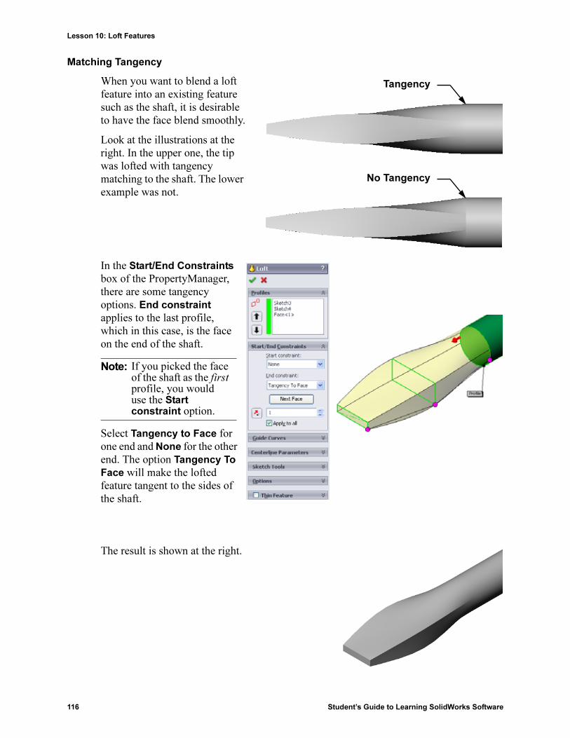
Lesson 10: Loft Features
116 Student’s Guide to Learning SolidWorks Software
Matching Tangency
When you want to blend a loft feature into an existing feature such as the shaft, it is desirable to have the face blend smoothly.
Look at the illustrations at the right. In the upper one, the tip was lofted with tangency matching to the shaft. The lower example was not.
In the Start/End Constraints box of the PropertyManager, there are some tangency options. End constraint applies to the last profile, which in this case, is the face on the end of the shaft.
Select Tangency to Face for one end and None for the other end. The option Tangency To
Face will make the lofted feature tangent to the sides of the shaft.
The result is shown at the right.
Note: If you picked the face of the shaft as the first profile, you would use the Start constraint option.
Tangency
No Tangency
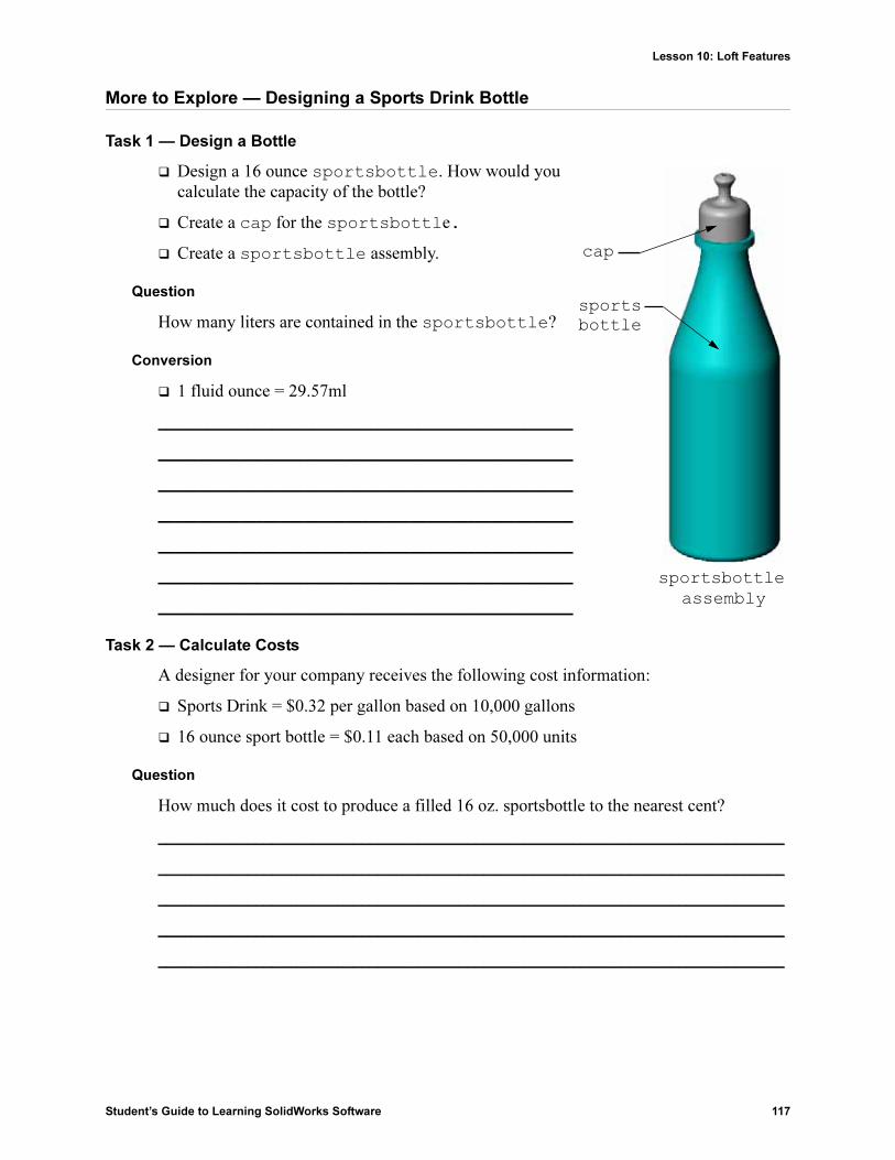
Lesson 10: Loft Features
Student’s Guide to Learning SolidWorks Software 117
More to Explore — Designing a Sports Drink Bottle
Task 1 — Design a Bottle
� Design a 16 ounce sportsbottle. How would you calculate the capacity of the bottle?
� Create a cap for the sportsbottle.
� Create a sportsbottle assembly.
Question
How many liters are contained in the sportsbottle?
Conversion
� 1 fluid ounce = 29.57ml
___________________________________________________
___________________________________________________
___________________________________________________
___________________________________________________
___________________________________________________
___________________________________________________
___________________________________________________
Task 2 — Calculate Costs
A designer for your company receives the following cost information:
� Sports Drink = $0.32 per gallon based on 10,000 gallons
� 16 ounce sport bottle = $0.11 each based on 50,000 units
Question
How much does it cost to produce a filled 16 oz. sportsbottle to the nearest cent?
_____________________________________________________________________________
_____________________________________________________________________________
_____________________________________________________________________________
_____________________________________________________________________________
_____________________________________________________________________________
cap
sports bottle
sportsbottle assembly

Lesson 10: Loft Features
118 Student’s Guide to Learning SolidWorks Software
Lesson Summary
� A Loft blends multiple profiles together.
� A Loft feature can be a base, boss, or cut.
� Neatness counts!
• Select the profiles in order.
• Click corresponding points on each profile.
• The vertex closest to the selection point is used.

Student’s Guide to Learning SolidWorks Software 119
11
Lesson 11: Visualization
Goals of This Lesson
� Create an image with the PhotoWorks™ application.
� Create an animation using SolidWorks MotionManager.
Before Beginning This Lesson
� This lesson requires copies of Tutor1, Tutor2 and the Tutor assembly that are found in the Lessons\Lesson11 folder. Tutor1, Tutor2 and the Tutor assembly were built earlier in the course.
� This lesson also requires the Claw-Mechanism that was built earlier in the course. A copy of this assembly is located in the Lessons\Lesson11\Claw folder.
� Verify that PhotoWorks is set up and running on your classroom/lab computers.
Resources for This Lesson
This lesson plan corresponds to Working with Models: PhotoWorks and Working with
Models: Animation in the SolidWorks Tutorials.
Combine photorealistic images and animations to create professional presentations.

Lesson 11: Visualization
120 Student’s Guide to Learning SolidWorks Software
Competencies for Lesson 11
You develop the following competencies in this lesson:
� Engineering: Enhance the appeal of a product with visualization and animation.
� Technology: Work with different file formats to enhance presentation skills.
Active Learning Exercises — Using PhotoWorks
Follow the instructions in Working with Models: PhotoWorks in the SolidWorks Tutorials. Then create a PhotoWorks rendering of Tutor1 which you built in a previous lesson.
� Apply Chrome appearance.
� Set the Background Style to Graduated.
� Save the Tutor Rendering.bmp image.
The step-by-step instructions are as follows:
Getting Started
1 Click Open on the Standard toolbar, and open the part Tutor1 which you built earlier.
2 Set the view orientation to Isometric and click Shaded on the View toolbar. Your part should look like the illustration at the right.
Shaded Rendering
Shaded rendering is the basis for all photo-realistic rendering in PhotoWorks.
1 Click Render on the PhotoWorks toolbar.
The PhotoWorks software produces a smooth-shaded rendering of the part using a default appearance and scene.

Lesson 11: Visualization
Student’s Guide to Learning SolidWorks Software 121
Applying an Appearance
1 Click Appearance on the PhotoWorks toolbar. The Appearances PropertyManager opens and the Appearances/
PhotoWorks tab appears in the Task Pane.
The top pane of the Appearances/PhotoWorks tab in the Task Pane is the Appearance Library where appearances are listed in folders. Each folder can be expanded by clicking the plus sign next to it to show the sub-folders. The bottom pane is the Appearance Selection area.
2 Open the Metal folder and then open the Chrome sub-folder. The appearance selection area displays a rendered image of a sphere for each appearance in the class.
3 Click on the chromium plate appearance.
4 Click OK in the Appearances PropertyManager.
5 Click Render .
The part is rendered with a chrome surface.
What Makes an Image Look Realistic?
Highly reflective surfaces such as chrome are visually more interesting when there are details in the environment for them to reflect. Compare the image with the plain graduated background with the one that has the complex background, with floor and walls. Notice the reflections in the part.

Lesson 11: Visualization
122 Student’s Guide to Learning SolidWorks Software
Set the Background Style to Graduated
1 Click Scene on the PhotoWorks toolbar. The Scene Editor opens.
2 Open the Presentation Scenes folder.
3 Select Garage Room.
4 Click Apply and Close.
5 Click Render .
Saving the Image
You can save a PhotoWorks image to a file for design proposals, technical documentation and product presentations. Images can be rendered to many file types, including: .bmp, .jpg. .tif, and so on.
To Save the Image:
1 Click Render to File on the PhotoWorks toolbar.
2 In the Render to File window, specify a filename for the image.
3 In the Format field, specify a file type to save the image as.
4 Save the file in the directory as instructed by your teacher.
5 Optionally, you may set the Width, and Height.
6 Click Render.
Note: If you change the Image size, you should use Fixed aspect ratio to prevent distorting the image.

Lesson 11: Visualization
Student’s Guide to Learning SolidWorks Software 123
Active Learning Exercises — Creating an Animation
Create an animation of the 4-bar linkage. Follow the instructions in Working with
Models: Animation in the SolidWorks Tutorials.
Lesson 11 — 5 Minute Assessment
Name: _______________________________Class: _________ Date:_______________
Directions: Answer each question by writing the correct answer or answers in the space
provided or circle the answer as directed.
1 What is PhotoWorks?
_____________________________________________________________________
2 List the rendering effects that are used in PhotoWorks?
_____________________________________________________________________
3 The PhotoWorks_________ ___________ enables you to specify and preview appearances.
4 Where do you set the scene background?
_____________________________________________________________________
5 What is SolidWorks MotionManager?
_____________________________________________________________________
_____________________________________________________________________
6 List the three types of animations that can be created using the AnimationWizard.
_____________________________________________________________________

Lesson 11: Visualization
124 Student’s Guide to Learning SolidWorks Software
Exercises and Projects — Creating an Exploded View of an Assembly
Using PhotoWorks and MotionManager Together
When you record an animation, the default rendering engine that is used is the SolidWorks shaded image software. This means the shaded images that make up the animation will look just like the shaded images you see in SolidWorks.
Earlier in this lesson you learned how to make photo-realistic images using the PhotoWorks application. You can record animations that are rendered using the PhotoWorks software. Since PhotoWorks rendering is much slower than SolidWorks shading, recording an animation this way takes much more time.
To use the PhotoWorks rendering software select PhotoWorks buffer from the Renderer: list on the Save Animation to
File dialog box.
Creating an Exploded View of an Assembly
The Claw-Mechanism which you used earlier already had an exploded view. To add an exploded view to an assembly, the Tutor assembly for example, follow this procedure:
1 Click Open on the Standard toolbar, and open the assembly, Tutor, which you built earlier.
2 Click Insert, Exploded View... or click Exploded View on the Assembly toolbar.
The Explode PropertyManager appears.
Note: The file types *.bmp and *.avi increase in file size as more appearances and advanced rendering effects are applied. The larger the image size the more time is required to create the image and animation files.

Lesson 11: Visualization
Student’s Guide to Learning SolidWorks Software 125
3 The Explode Steps section of the dialog displays the explode steps in sequence, and is used to edit, navigate through, or delete explode steps. Each movement of a component in a single direction is considered a step.
The Settings section of the dialog controls the details of each explode step, including what component(s), what direction, and how far to move each component. The simplest way is just to drag the component(s).
4 First select a component to begin a new explode step. Select Tutor1; a reference triad appears on the model.Next choose the other explode criteria:
• Direction to explode along
The default is Along Z ([email protected]), the blue triad pointer. A different direction can be specified by selecting a different arrow of the triad or a model edge.
• Distance
The distance the component is exploded can be done by eye in the graphics area, or more exactly by manipulating the value in the dialog.
5 Click on the blue triad arrow, and drag the part to the left. It is constrained to this axis (Along Z).
Drag the part to the left by clicking and holding the left mouse button.

Lesson 11: Visualization
126 Student’s Guide to Learning SolidWorks Software
6 When the part is released (release the left mouse button), the explode step is created. The part or parts are displayed under the step in the tree.
7 The explode distance can be changed by editing the step. Right-click on Explode Step1, and select Edit Step. Change the distance to 70mm, and click Apply.
8 Since there is only one component to explode, this completes making the exploded view.
9 Click OK to close the Explode PropertyManager.
10 To collapse an exploded view, right-click the assembly icon at the top of the FeatureManager design tree, and select Collapse from the shortcut menu.
11 To explode an existing exploded view, right-click the assembly icon in the FeatureManager design tree, and select Explode from the shortcut menu.
Note: Exploded views are related to and stored in configurations. You can have only one exploded view per configuration.

Lesson 11: Visualization
Student’s Guide to Learning SolidWorks Software 127
Exercises and Projects — Creating and Modifying Renderings
Task 1 — Creating a Rendering of a Part
Create a PhotoWorks rendering of Tutor2. Use the following settings:
� Use old english brick2 appearance from the stone\brick class. Adjust the scale to your liking.
� Set the background to Plain White from Basic Scenes.
� Render and save the image.
Task 2 — Modifying a Rendering of a Part
Modify the PhotoWorks rendering of Tutor1 that you created in the preceding Active Learning Exercise. Use the following settings:
� Change the appearance to wet concrete2d from the Stone\Paving class.
� Set the background to Plain White from Basic Scenes.
� Render and save the image.
Task 3 — Creating a Rendering of an Assembly
Create a PhotoWorks rendering of the Tutor assembly. Use the following settings:
� Set the scene to Courtyard Background from Presentation Scenes.
� Render and save the image.
Task 4 — Rendering Additional Parts
Create PhotoWorks renderings of any of the parts and assemblies you built during class. For example, you might render the candlestick or the sports bottle you made created earlier. Experiment with different appearances and scenes. You can try to create as realistic an image as possible, or you can create some unusual visual effects. Use your imagination. Be creative. Have fun.

Lesson 11: Visualization
128 Student’s Guide to Learning SolidWorks Software
Exercises and Projects — Creating an Animation
Create an animation that shows how the slides move relative to each other. In other words, create an animation where at least one of the slides moves. You cannot accomplish this task with the Animation Wizard.
1 Open the Nested Slides assembly. It is located in the Lesson11 folder.
2 Select the Motion Study1 tab at the bottom of the graphics area to access the MotionManager controls.
3 The parts are in their initial position. Move the time bar to 00:00:05.
4 Select Slide1, the innermost slide. Drag Slide1 so that it is almost completely out of Slide2.
5 Next drag Slide2 about halfway out of Slide3. The MotionManager shows with green bars that the two slides are set to move in this time frame.
6 Click Calculate on the MotionManager Toolbar to process and preview the animation. Once calculated, use the Play and Stop controls.
7 If desired, you can cycle the animation by using the Reciprocate command.
Or, to create an animation of the complete cycle, move the time bar forward (to 00:00:10), then return the components to their original positions.
8 Save the animation to an .avi file.

Lesson 11: Visualization
Student’s Guide to Learning SolidWorks Software 129
Exercises and Projects — Creating an Animation of the Claw-Mechanism
Create an animation of the Claw-Mechanism. Some suggestions include exploding and collapsing, and moving the Collar up and down to show assembly motion.
A completed copy of the Claw-Mechanism is located in the Lesson11 folder. This version is slightly different than the one you built in Lesson 4. This one does not have a component pattern. Each component was assembled individually. This is so the assembly will explode better.
More to Explore — Creating an Animation of Your Own Assembly
Earlier you created an animation from an existing assembly. Now create an animation of the Tutor assembly that you built earlier, using the Animation Wizard . The animation should include the following:
� Explode the assembly for a duration of 3 seconds.
� Rotate the assembly around the Y axis for a duration of 8 seconds.
� Collapse the assembly for a duration of 3 seconds.
� Record the animation. Optional: Record the animation using the PhotoWorks renderer.

Lesson 11: Visualization
130 Student’s Guide to Learning SolidWorks Software
Lesson Summary
� PhotoWorks and SolidWorks MotionManager create realistic representations of models.
� PhotoWorks uses realistic textures, appearances, lighting, and other effects to produce true to life models.
� SolidWorks MotionManager animates and captures motion of SolidWorks parts and assemblies.
� SolidWorks MotionManager generates Windows-based animations (*.avi files). The *.avi file uses a Windows-based Media Player.

Student’s Guide to Learning SolidWorks Software 131
12
Lesson 12: SolidWorks SimulationXpress
Goals of This Lesson
� Understand basic concepts of stress analysis.
� Calculate the stress and displacement in the following part subjected to a load.
Before Beginning This Lesson
� If SolidWorks Simulation is active, you must clear it from the Add-Ins list of compatible software products to access SolidWorks SimulationXpress. Click Tools, Add-Ins and clear the check mark in front of SolidWorks Simulation.
Resources for This Lesson
This lesson plan corresponds to Design Analysis: SolidWorks SimulationXpress in the SolidWorks Tutorials.
The Simulation Guides, Sustainability Guide, Structural Bridge, Race Car, Mountain Board, and Trebuchet Design Projects apply concepts of engineering, math, and science. Click Help, Student Curriculum.
Fix this face.
Apply 1500lb forceon these faces.
von Mises stress plot

Lesson 12: SolidWorks SimulationXpress
132 Student’s Guide to Learning SolidWorks Software
Competencies for Lesson 12
You develop the following competencies in this lesson:
� Engineering: Explore how material properties, forces, and restraints affect part behavior.
� Technology: Knowledge of the finite element process to analyze force and pressure on a part.
� Math: Understand units and apply matrices.
� Science: Investigate density, volume, force, and pressure.
Active Learning Exercises — Analyze a Hook and a Control Arm
Follow the instructions in Design Analysis: SolidWorks
SimulationXpress: SimulationXpress Basic Functionality in the SolidWorks Tutorials. In this lesson, you determine the maximum von Mises stress and displacement after subjecting the hook to a load.
Follow the instructions in Design Analysis: SolidWorks
SimulationXpress: Using Analysis to Save Material in the SolidWorks Tutorials. In this lesson, you use the results from SolidWorks SimulationXpress to reduce the volume of a part.
Fix this face.
Apply 1500lb forceon these faces.
Fix this face.
Apply a vertical forceof 4000 N on this face.

Lesson 12: SolidWorks SimulationXpress
Student’s Guide to Learning SolidWorks Software 133
Lesson 12 — 5 Minute Assessment
Name: _______________________________Class: _________ Date:_______________
Directions: Answer each question by writing the correct answer or answers in the space
provided or circle the answer as directed.
1 How do you start SolidWorks SimulationXpress?
_____________________________________________________________________
2 What is analysis?
_____________________________________________________________________
3 Why is analysis important?
__________________________________________________________________________________________________________________________________________
4 What does static analysis calculate?
__________________________________________________________________________________________________________________________________________
5 What is stress?
_____________________________________________________________________
6 SolidWorks SimulationXpress reports that the factor of safety is 0.8 at some locations. Is the design safe?
_____________________________________________________________________
_____________________________________________________________________

Lesson 12: SolidWorks SimulationXpress
134 Student’s Guide to Learning SolidWorks Software
Exercises and Projects — Analyze a CD Storage Box
You are part of the design team that created the storagebox to hold the CD cases in an earlier lesson. In this lesson, you use SimulationXpress to analyze the storagebox. First, you determine the deflection of storagebox under the weight of 25 CD cases. Then, you modify the wall thickness of the storagebox, perform another analysis, and compare the deflection to the original value.
Task 1 — Calculate the Weight of the CD Cases
You are given the measurements of a single CD case as shown. Storagebox holds 25 CD cases. The density of the material used for the CD cases is 1.02 g/cm^3.
What is the weight of 25 CD cases in pounds?
____________________________________________
____________________________________________
____________________________________________
____________________________________________
____________________________________________
Task 2 — Determine the Displacement in the Storage Box
Determine the maximum displacement of storagebox under the weight of 25 CD cases.
1 Open storagebox.sldprt in the Lesson12 file folder.
2 Click Tools, SimulationXpress to start SolidWorks SimulationXpress.
Options
Set the units to English (IPS) to enter the force in pounds and see the deflection in inches.
1 In the SolidWorks SimulationXpress Task pane, click Options.
2 Select English (IPS) for System of Units.
3 Click OK.
4 Click Next in the Task pane.
Material
Choose a solid nylon material for storagebox from the library of standard materials.
1 Click Material in the Task pane, then click Change material.
2 In the Plastics folder, select Nylon 101, click Apply, then click Close.
3 Click Next.

Lesson 12: SolidWorks SimulationXpress
Student’s Guide to Learning SolidWorks Software 135
Fixtures/Restraints
Restrain the back face of storagebox to simulate hanging the box on a wall. Restrained faces are fixed; they do not move during the analysis. In reality, you would probably hang the box using a couple screws but we will restain the entire back face.
1 Click Fixtures in the Task pane, then click Add a fixture.
2 Select the back face of storagebox to restrain that face, then click OK in the PropertyManager.
3 Click Next in the Task pane.
Loads
Apply a load inside storagebox to simulate the weight of the 25 CD cases.
1 Click Loads in the Task pane, then click Add a force.
2 Select the inside face of storagebox to apply the load to that face.
3 Type 10 for the value of the force in pounds. Make sure the direction is set to Normal. Click OK in the PropertyManager.
4 Click Next in the Task pane.
Analyze
Perform the analysis to calculate displacements, strains, and stresses.
1 Click Run in the Task pane, then click Run Simulation.
2 After analysis is complete, click Yes, continue to display the Factor of Safety plot.
Results
View the results.
What is the maximum displacement?
__________________________________________________________________
__________________________________________________________________
__________________________________________________________________
Task 3 — Determine the Displacement in a Modified Storage Box
The current wall thickness is 1 centimeter. What if you changed the wall thickness to 1 millimeter? What would the maximum displacement be?
__________________________________________________________________
__________________________________________________________________
__________________________________________________________________
Select this face.
Select this face.

Lesson 12: SolidWorks SimulationXpress
136 Student’s Guide to Learning SolidWorks Software
More to Explore — Analysis Examples
The Design Analysis: SolidWorks SimulationXpress: Analysis Examples section of the SolidWorks Tutorials contains four additional examples. This section does not provide a step-by-step procedural discussion that shows you how to perform each step of the analysis in detail. Rather the purpose of this section is to show examples of analysis, provide a description of the analysis, and outline the steps to complete the analysis.
Task 1 — Analyze the Anchor Plate
Determine the maximum force that the anchor plate can support while maintaining a factor of safety of 3.0.
Task 2 — Analyze the Spider
Based on a factor of safety of 2.0, find out the maximum force that the spider can support when a) all outer holes are fixed, b) two outer holes are fixed, and c) only one outer hole is fixed.
Task 3 — Analyze the Link
Determine the maximum force that you can safely apply to each arm of the link.
Task 4 — Analyze the Faucet
Calculate the magnitudes of the front and sideways horizontal forces that will cause the faucet to yield.
von Mises (psi)
von Mises (psi)
von Mises (psi)

Lesson 12: SolidWorks SimulationXpress
Student’s Guide to Learning SolidWorks Software 137
More to Explore — Other Guides and Projects
There are additional guides and projects that teach simulation and analysis.
Introduction to Analysis Guides
These guides include:
� An Introduction to Stress Analysis Applications with SolidWorks Simulation. Features an introduction to the principles of stress analysis. Fully integrated with SolidWorks, design analysis is an essential part of completing a product. SolidWorks tools simulate the testing of your model’s prototype working environment. It can help answer questions such as how safe, efficient, and economical is your design?
� An Introduction to Flow Analysis Applications with SolidWorks Flow Simulation. Features an introduction to SolidWorks Flow Simulation. This is an analysis tool for predicting the characteristics of various flows over and inside 3D objects modeled by SolidWorks, thereby solving various hydraulic and gas dynamic engineering problems.
� An Introduction to Motion Analysis Applications with SolidWorks Motion. Features an introduction to SolidWorks Motion with step-by-step examples to incorporate dynamic and kinematic theory through virtual simulation.
Trebuchet Design Project
The Trebuchet Design Project document steps a student through the parts, assemblies, and drawings used to construct a trebuchet. Utilizing SolidWorks SimulationXpress, students analyze structural members to determine material and thickness.
Mathematics and physics competency-based exercises explore algebra, geometry, weight, and gravity.
An optional hands-on construction with models is provided by Gears Education Systems, LLC.
stress analysis flow analysis motion analysis

Lesson 12: SolidWorks SimulationXpress
138 Student’s Guide to Learning SolidWorks Software
Structural Bridge Design Project
The Structural Bridge Design Project document steps a student through the engineering method for constructing a trussed wooden bridge. Students utilize SolidWorks Simulation to analyze different loading conditions of the bridge.
An optional hands-on activity is provided by Pitsco, Inc., with classroom kits.
CO2 Car Design Project
The CO2 Car Design Project document leads students through the steps of designing and analyzing a CO2-powered car, from the car body design in SolidWorks to the analysis of air flow in SolidWorks Flow Simulation. Students must make design changes in the car body to reduce drag.
They will also explore the design process through production drawings.
An optional hands-on activity is provided by Pitsco, Inc., with classroom kits.
SolidWorks Sustainability
From raw material extraction and manufacturing to product use and disposal, SolidWorks Sustainability shows designers how the choices they make can change the overall environmental impact of any product they create. SolidWorks Sustainability measures the environmental impact over the life cycle of your product in terms of four factors: carbon footprint, air acidification, water eutrophication, and total energy consumed.
The SolidWorks Sustainability document leads students through the environmental impact of a brake assembly. Students analyze the entire brake assembly and take a closer look at a single part, the rotor.

Lesson 12: SolidWorks SimulationXpress
Student’s Guide to Learning SolidWorks Software 139
Lesson Summary
� SolidWorks SimulationXpress is fully integrated in SolidWorks.
� Design analysis can help you design better, safer, and cheaper products.
� Static analysis calculates displacements, strains, stresses, and reaction forces.
� Materials start to fail when stress reach a certain limit.
� von Mises stress is a number that gives an overall idea about the state of stresses at a location.
� SolidWorks SimulationXpress calculates the factor of safety at a point by dividing the yield strength of the material by the von Mises stress at that point. A factor of safety of less than 1.0 indicates that the material at that location has yielded and the design is not safe.

Lesson 12: SolidWorks SimulationXpress
140 Student’s Guide to Learning SolidWorks Software

Student’s Guide to Learning SolidWorks Software 141
G
Glossary
animate View a model or eDrawing in a dynamic manner. Animation simulates motion or displays different views.
assembly An assembly is a document in which parts, features, and other assemblies (sub-assemblies) are mated together. The parts and sub-assemblies exist in documents separate from the assembly. For example, in an assembly, a piston can be mated to other parts, such as a connecting rod or cylinder. This new assembly can then be used as a sub-assembly in an assembly of an engine. The extension for a SolidWorks assembly file name is.SLDASM. See also sub-assembly and mate.
axis An axis is a straight line that can be used to create model geometry, features, or patterns. An axis can be made in a number of different ways, including using the intersection of two planes. See also temporary axis, reference geometry
block A block is a user-defined annotation for drawings only. A block can contain text, sketch entities (except points), and area hatch, and it can be saved in a file for later use as, for example, a custom callout or a company logo.
boss/base A base is the first solid feature of a part, created by a boss. A boss is a feature that creates the base of a part, or adds material to a part, by extruding, revolving, sweeping, or lofting a sketch, or by thickening a surface.
broken-outsection
A broken-out section exposes inner details of a drawing view by removing material from a closed profile, usually a spline.
chamfer A chamfer bevels a selected edge or vertex.
click-click As you sketch, if you click and then release the pointer, you are in click-click mode. Move the pointer and click again to define the next point in the sketch sequence.
click-drag As you sketch, if you click and drag the pointer, you are in click-drag mode. When you release the pointer, the sketch entity is complete.

Glossary
142 Student’s Guide to Learning SolidWorks Software
closed profile A closed profile (or closed contour) is a sketch or sketch entity with no exposed endpoints; for example, a circle or polygon.
collapse Collapse is the opposite of explode. The collapse action returns an exploded assembly's parts to their normal positions.
component A component is any part or sub-assembly within an assembly.
configuration A configuration is a variation of a part or assembly within a single document. Variations can include different dimensions, features, and properties. For example, a single part such as a bolt can contain different configurations that vary the diameter and length. See design table.
ConfigurationManager
The ConfigurationManager on the left side of the SolidWorks window is a means to create, select, and view the configurations of parts and assemblies.
cut A feature that removes material from a part.
coordinatesystem
A coordinate system is a system of planes used to assign Cartesian coordinates to features, parts, and assemblies. Part and assembly documents contain default coordinate systems; other coordinate systems can be defined with reference geometry. Coordinate systems can be used with measurement tools and for exporting documents to other file formats.
degrees offreedom
Geometry that is not defined by dimensions or relations is free to move. In 2D sketches, there are three degrees of freedom: movement along the X and Y axes, and rotation about the Z axis (the axis normal to the sketch plane). In 3D sketches and in assemblies, there are six degrees of freedom: movement along the X, Y, and Z axes, and rotation about the X, Y, and Z axes. See under defined.
design table A design table is an Excel spreadsheet that is used to create multiple configurations in a part or assembly document. See configurations.
document A SolidWorks document is a file containing a part, assembly, or drawing.
drawing A drawing is a 2D representation of a 3D part or assembly. The extension for a SolidWorks drawing file name is.SLDDRW.
drawing sheet A drawing sheet is a page in a drawing document.
edge The boundary of a face.
eDrawing Compact representation of a part, assembly, or drawing. eDrawings are compact enough to email and can be created for a number of CAD file types including SolidWorks.

Glossary
Student’s Guide to Learning SolidWorks Software 143
face A face is a selectable area (planar or otherwise) of a model or surface with boundaries that help define the shape of the model or surface. For example, a rectangular solid has six faces. See also surface.
feature A feature is an individual shape that, combined with other features, makes up a part or assembly. Some features, such as bosses and cuts, originate as sketches. Other features, such as shells and fillets, modify a feature's geometry. However, not all features have associated geometry. Features are always listed in the FeatureManager design tree. See also surface, out-of-context feature.
FeatureManagerdesign tree
The FeatureManager design tree on the left side of the SolidWorks window provides an outline view of the active part, assembly, or drawing.
fillet A fillet is an internal rounding of a corner or edge in a sketch, or an edge on a surface or solid.
graphics area The graphics area is the area in the SolidWorks window where the part, assembly, or drawing appears.
helix A helix is defined by pitch, revolutions, and height. A helix can be used, for example, as a path for a swept feature cutting threads in a bolt.
instance An instance is an item in a pattern or a component that occurs more than once in an assembly.
layer A layer in a drawing can contain dimensions, annotations, geometry, and components. You can toggle the visibility of individual layers to simplify a drawing or assign properties to all entities in a given layer.
line A line is a straight sketch entity with two endpoints. A line can be created by projecting an external entity such as an edge, plane, axis, or sketch curve into the sketch.
loft A loft is a base, boss, cut, or surface feature created by transitions between profiles.
mate A mate is a geometric relationship, such as coincident, perpendicular, tangent, and so on, between parts in an assembly. See also SmartMates.
mategroup A mategroup is a collection of mates that are solved together. The order in which the mates appear within the mategroup does not matter.

Glossary
144 Student’s Guide to Learning SolidWorks Software
mirror (1) A mirror feature is a copy of a selected feature, mirrored about a plane or planar face. (2) A mirror sketch entity is a copy of a selected sketch entity that is mirrored about a centerline. If the original feature or sketch is modified, the mirrored copy is updated to reflect the change.
model A model is the 3D solid geometry in a part or assembly document. If a part or assembly document contains multiple configurations, each configuration is a separate model.
mold A mold cavity design requires (1) a designed part, (2) a mold base that holds the cavity for the part, (3) an interim assembly in which the cavity is created, and (4) derived component parts that become the halves of the mold.
named view A named view is a specific view of a part or assembly (isometric, top, and so on) or a user-defined name for a specific view. Named views from the view orientation list can be inserted into drawings.
open profile An open profile (or open contour) is a sketch or sketch entity with endpoints exposed. For example, a U-shaped profile is open.
origin The model origin is the point of intersection of the three default reference planes. The model origin appears as three gray arrows and represents the (0,0,0) coordinate of the model. When a sketch is active, a sketch origin appears in red and represents the (0,0,0) coordinate of the sketch. Dimensions and relations can be added to the model origin, but not to a sketch origin.
over defined A sketch is over defined when dimensions or relations are either in conflict or redundant.
parameter A parameter is a value used to define a sketch or feature (often a dimension).
part A part is a single 3D object made up of features. A part can become a component in an assembly, and it can be represented in 2D in a drawing. Examples of parts are bolt, pin, plate, and so on. The extension for a SolidWorks part file name is .SLDPRT.
pattern A pattern repeats selected sketch entities, features, or components in an array, which can be linear, circular, or sketch-driven. If the seed entity is changed, the other instances in the pattern update.
planar An entity is planar if it can lie on one plane. For example, a circle is planar, but a helix is not.
plane Planes are flat construction geometry. Planes can be used for a 2D sketch, section view of a model, a neutral plane in a draft feature, and others.

Glossary
Student’s Guide to Learning SolidWorks Software 145
point A point is a singular location in a sketch, or a projection into a sketch at a single location of an external entity (origin, vertex, axis, or point in an external sketch). See also vertex.
profile A profile is a sketch entity used to create a feature (such as a loft) or a drawing view (such as a detail view). A profile can be open (such as a U shape or open spline) or closed (such as a circle or closed spline).
PropertyManager
The PropertyManager is on the left side of the SolidWorks window for dynamic editing of sketch entities and most features.
rebuild The rebuild tool updates (or regenerates) the document with any changes made since the last time the model was rebuilt. Rebuild is typically used after changing a model dimension.
relation A relation is a geometric constraint between sketch entities or between a sketch entity and a plane, axis, edge, or vertex. Relations can be added automatically or manually.
revolve Revolve is a feature tool that creates a base or boss, a revolved cut, or revolved surface by revolving one or more sketched profiles around a centerline.
section A section is another term for profile in sweeps.
section view A section view (or section cut) is (1) a part or assembly view cut by a plane, or (2) a drawing view created by cutting another drawing view with a section line.
shaded A shaded view displays a model as a colored solid. See also HLR, HLG, and wireframe.
sheet format A sheet format typically includes page size and orientation, standard text, borders, title blocks, and so on. Sheet formats can be customized and saved for future use. Each sheet of a drawing document can have a different format.
shell Shell is a feature tool that hollows out a part, leaving open the selected faces and thin walls on the remaining faces. A hollow part is created when no faces are selected to be open.
sketch A 2D sketch is a collection of lines and other 2D objects on a plane or face that forms the basis for a feature such as a base or a boss. A 3D sketch is non-planar and can be used to guide a sweep or loft, for example.
SmartMates A SmartMate is an assembly mating relation that is created automatically. See mate.

Glossary
146 Student’s Guide to Learning SolidWorks Software
sub-assembly A sub-assembly is an assembly document that is part of a larger assembly. For example, the steering mechanism of a car is a sub-assembly of the car.
surface A surface is a zero-thickness planar or 3D entity with edge boundaries. Surfaces are often used to create solid features. Reference surfaces can be used to modify solid features. See also face.
sweep A sweep creates a base, boss, cut, or surface feature by moving a profile (section) along a path.
template A template is a document (part, assembly, or drawing) that forms the basis of a new document. It can include user-defined parameters, annotations, or geometry.
Toolbox A library of standard parts that are fully integrated with SolidWorks. These parts are ready-to-use components — such as bolts and screws.
under defined A sketch is under defined when there are not enough dimensions and relations to prevent entities from moving or changing size. See degrees of freedom.
vertex A vertex is a point at which two or more lines or edges intersect. Vertices can be selected for sketching, dimensioning, and many other operations.
wireframe Wireframe is a view mode in which all edges of the part or assembly are displayed. See also HLR, HLG, shaded.

Student’s Guide to Learning SolidWorks Software 147
A
Appendix A: Certified SolidWorks Associate Program
Certified SolidWorks Associate (CSWA)
The Certified SolidWorks Associate (CSWA) Certification Program provides the skills students need to work in the design and engineering fields. Successfully passing the CSWA Exam assessment proves competency in 3D CAD modeling technology, application of engineering principles, and recognition of global industry practices.
The exam features hands-on challenges in many of these areas:
� Sketch entities - lines, rectangles, circles, arcs, ellipses, centerlines
� Sketch tools - offset, convert, trim
� Sketch relations
� Boss and cut features - extrudes, revolves, sweeps, lofts
� Fillets and chamfers
� Linear, circular and fill patterns
� Dimensions
� Feature conditions – start and end
� Mass properties
� Materials
� Inserting components
� Standard mates - coincident, parallel, perpendicular, tangent, concentric, distance, angle
� Reference geometry – planes, axis, mate references
� Drawing sheets and views
� Dimensions and model items
� Annotations
� SimulationXpress
Learn more at http://www.solidworks.com/cswa.
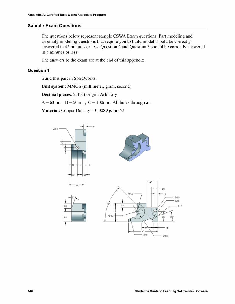
Appendix A: Certified SolidWorks Associate Program
148 Student’s Guide to Learning SolidWorks Software
Sample Exam Questions
The questions below represent sample CSWA Exam questions. Part modeling and assembly modeling questions that require you to build model should be correctly answered in 45 minutes or less. Question 2 and Question 3 should be correctly answered in 5 minutes or less.
The answers to the exam are at the end of this appendix.
Question 1
Build this part in SolidWorks.
Unit system: MMGS (millimeter, gram, second)
Decimal places: 2. Part origin: Arbitrary
A = 63mm, B = 50mm, C = 100mm. All holes through all.
Material: Copper Density = 0.0089 g/mm^3

Appendix A: Certified SolidWorks Associate Program
Student’s Guide to Learning SolidWorks Software 149
What is the overall mass of the part in grams?
a) 1205
b) 1280
c) 144
d) 1108
Question 2
SolidWorks SimulationXpress allows changes to mesh settings. Which of the following statements is False?
a) A fine mesh setting produces more accurate results than a course mesh.
b) A coarse mesh setting produces less accurate results than a fine mesh.
c) A fine mesh setting can be applied to a specific face instead of the entire model.
d) All of the above
Question 3
To create drawing view, ‘B’ it is necessary to sketch a spline (as shown) on drawing view ‘A’ and insert which SolidWorks view type?
a) Broken-out Section
b) Aligned Section
c) Section
d) Detail

Appendix A: Certified SolidWorks Associate Program
150 Student’s Guide to Learning SolidWorks Software
Question 4
Build this assembly in SolidWorks.
It contains 3 machined brackets and 2 pins.
Brackets: 2mm thickness, and equal size (holes through-all). Material: 6061 Alloy, Density = 0.0027g/mm^3. The top edge of the notch is located 20 mm from the top edge of the MachinedBracket.
Pins: 5 mm length and equal in diameter, Material: Titanium, Density = 0.0046g/mm^3. Pins are mated concentric to bracket holes (no clearance). Pin end faces are coincident to bracket outer faces. There is a 1 mm gap between the brackets. Brackets are positioned with equal angle mates (45 degrees).
Unit system: MMGS (millimeter, gram, second)
Decimal places: 2
Assembly origin: As shown.
What is the center of mass of the assembly?
a) X = -11.05 Y = 24.08 Z = -40.19
b) X = -11.05 Y = -24.08 Z = 40.19
c) X = 40.24 Y = 24.33 Z = 20.75
d) X = 20.75 Y = 24.33 Z = 40.24

Appendix A: Certified SolidWorks Associate Program
Student’s Guide to Learning SolidWorks Software 151
Question 5
Build this assembly in SolidWorks. It contains 3 components: Base, Yoke, Adjusting Pin. Apply the MMGS unit system.
Material: 1060 Alloy for all components. Density = 0.0027g/mm^3
Base: The distance between the front face of the Base and the front face of the Yoke = 60mm.
Yoke: The Yoke fits inside the left and right square channels of the Base component, (no clearance). The top face of the Yoke contains a Ø12mm through-all hole.
AdjustingPin: The bottom face of the AdjustingPin head is located 40 mm from the top face of the Yoke component. The AdjustingPin component contains a Ø5mm though all hole.
What is the center of mass of the assembly with respect to the illustrated coordinate system?
a) X = -30.00 Y = -40.16 Z = -40.16
b )X = 30.00 Y = 40.16 Z = -43.82
c) X = -30.00 Y = -40.16 Z = 50.20
d) X = 30.00 Y = 40.16 Z = -53.82

Appendix A: Certified SolidWorks Associate Program
152 Student’s Guide to Learning SolidWorks Software
Question 6
Build this part in SolidWorks.
Material: 6061 Alloy. Density = 0.0027g/mm^3
Unit system: MMGS (millimeter, gram, second)
Decimal places: 2.
Part origin: Arbitrary
A = 100.
All holes through all, unless otherwise specified
What is the overall mass of the part in grams?
a) 2040.57
b) 2004.57
c) 102.63
d) 1561.23

Appendix A: Certified SolidWorks Associate Program
Student’s Guide to Learning SolidWorks Software 153
More Information and Answers
For further preparation, please complete the SolidWorks tutorials, located in SolidWorks under the Help Menu, before taking the CSWA Exam. Review the “About the CSWA Exam” document located at http://www.solidworks.com/cswa.
Good Luck,
Certification Program Manager, SolidWorks Corporation
Correct answers
1 b
2 c
3 a
4 c
5 d
6 a

Appendix A: Certified SolidWorks Associate Program
154 Student’s Guide to Learning SolidWorks Software