Embed Size (px)
Citation preview
sensors
Review
Giant Magnetoresistance Sensors: A Review onStructures and Non-Destructive Eddy CurrentTesting Applications
Damhuji Rifai 1,2,*, Ahmed N. Abdalla 1,†, Kharudin Ali 2,† and Ramdan Razali 1,†
1 Faculty of Engineering Technology, Universiti Malaysia Pahang, Gambang, Pahang 26300, Malaysia;[email protected] (A.N.A.); [email protected] (R.R.)
2 Faculty of Electrical & Automation Engineering Technology. TATI University College, Kemaman 26000,Terengganu, Malaysia; [email protected]
* Correspondence: [email protected]; Tel.: +60-98-601-000† These authors contributed equally to this work.
Academic Editors: Subhas Mukhopadhyay and Chinthaka Pasan GooneratneReceived: 10 January 2016; Accepted: 18 February 2016; Published: 26 February 2016
Abstract: Non-destructive eddy current testing (ECT) is widely used to examine structural defects inferromagnetic pipe in the oil and gas industry. Implementation of giant magnetoresistance (GMR)sensors as magnetic field sensors to detect the changes of magnetic field continuity have increasedthe sensitivity of eddy current techniques in detecting the material defect profile. However, not manyresearchers have described in detail the structure and issues of GMR sensors and their applicationin eddy current techniques for nondestructive testing. This paper will describe the implementationof GMR sensors in non-destructive testing eddy current testing. The first part of this paper willdescribe the structure and principles of GMR sensors. The second part outlines the principles andtypes of eddy current testing probe that have been studied and developed by previous researchers.The influence of various parameters on the GMR measurement and a factor affecting in eddy currenttesting will be described in detail in the third part of this paper. Finally, this paper will discuss thelimitations of coil probe and compensation techniques that researchers have applied in eddy currenttesting probes. A comprehensive review of previous studies on the application of GMR sensors innon-destructive eddy current testing also be given at the end of this paper.
Keywords: giant magnetoresistance; eddy current testing; non-destructive testing
1. Introduction
Non-destructive testing (NDT) is a quality control tool that is extremely important in heavyengineering sectors such as the petroleum and gas industry. It is the last test before a component,system or process are deemed safe to run. In the petroleum industry, non-destructive testing is widelyused in detecting defects in the storage tanks and pipes that deliver oil and gas. Failure to detect andprovide accurate information about the status of quality components, systems or processes may resultin an accident that ends with the destruction of property and loss of life. Table 1 shows an overview ofthe major nondestructive testing techniques that are widely used in the oil and gas industry. With ofthe existing conventional NDT it is impossible to conduct inspections through the hundreds kilometersof a pipeline system used in the oil and gas industry. Thus, a simple and quick method to inspect thedefects in large pipe systems is necessary.
Eddy current testing (ECT) techniques are a non-destructive evaluation method for defectinspection on conductive materiald. The main advantages of ECT are that a diversity of inspectionscan be done using this technique, including surface and subsurface material defect inspections,
Sensors 2016, 16, 298; doi:10.3390/s16030298 www.mdpi.com/journal/sensors

Sensors 2016, 16, 298 2 of 30
thickness and coating measurements, electrical conductivity measurements for material classificationand conductive monitoring during material heat treatment [1]. Compared with another nondestructivetesting methods, this technique offers many advantages such as high sensitivity to small defects fortests that require fast scanning inspection. In addition, this technique also known as a techniquethat requires no physical contact between the probe and test subject [2]. This makes this techniqueparticularly suitable for continuous monitoring of growth defects in pipeline systems.
The sensitivity of non-destructive eddy current testing techniques can be improved by selectingan appropriate probe and an optimum frequency exciting coil for each type of crack and testedmaterial [3,4]. To monitor the growth of cracks in large system structures, the test probe is placed onthe detected cracks and the data continuously collected for defect profile analysis [1]. In this application,ECT techniques are more suitable than another non-destructive testing methods. Although ultrasonictesting techniques can provide an accurate defect profile, this technique requires a couplant as asignal transmission medium between the probe and testing material. For this reason, eddy currenttesting is still considered the best non-destructive testing technique [5]. Table 1 shows a comparison ofnon-destructive testing methods widely used in industry.
Eddy current testing can also be used to measure material thinning caused by corrosion. Thisapplication is widely used to measure the thinning that occurs in aircraft bodies and heat exchangertubes in nuclear plants.
The novel state of the art non-destructive testing eddy current techniques are derived fromelectromagnetic principles. The techniques are based on a non-uniform magnetic field induced in theconductive material due to the presence of defects to determine the profile of a defect in the materialbeing inspected [6–8]. Various material profiles can be obtained by using different exciting currentfrequencies. The magnetic field changes may provide information related to any defects inherent inthe material, electrical conductivity and permeability of the material after a heat treatment process,surface and subsurface defects. This discovery is the starting point for research on non-destructivetesting using the eddy current principle.
The accuracy and effectiveness of the non-destructive eddy current testing technique depend onthe sensitivities of the receiving coil probe used to detect the magnetic field changes caused by defectsin the material under testing. Application of the giant magnetoresistance (GMR) sensor as a signalreceiver has increased the sensitivity of this technique in the detection of small defects [9]. Integratingthis system with smart algorithms allows this technique to produce complete and comprehensiveprofile data. Implementation of GMR sensors in non-destructive eddy current techniques is still new,and many issues related to the hybrid system (coil-GMR) have not been explored by researchers. Thispaper will describe the implementation of GMR sensorw in non-destructive eddy current testingtechniques, a previous study of the applications of GMR sensor in non-destructive eddy current testingand the issues that need to be addressed by future researchers.
2. Overview of Giant Magnetoresistance Sensors
Research in the field of magnetic films has been carried out by researchers in recent years. Thediscovery of giant magnetoresistance (GMR) in 1988 provided scientists with a new perspectivefor understanding polarized carriers in ferromagnetic metals and possibilities to apply this in newtechnologies, particularly in non-destructive testing [8,9]. Obeid [10] in his study discussed the detailsof GMR structures.
GMR sensor have attracted the interest of many researchers and are widely used in variousapplications because these sensors have high bandwidths and sensitivity independent of the magneticfield. In addition, other advantages are the small dimensions of GMR sensors and the fact they requireonly a low power source. GMR sensors detect magnetic field vectors along the axis of the sensingtrack [11].

Sensors 2016, 16, 298 3 of 30
Table 1. Major NDT Methods—A comprehensive overview [7].
Method Principles Application Advantages Limitation
Visual Testing
Uses reflected or transmitted lightfrom test object that is image withthe human eye or other lightsensing device
Many application in manyindustries ranging from rawmaterial to finished products andin-service inspection
Can be inexpensive and simplewith minimal training required.Broad scope of uses and benefits
Only surface conditions can beevaluated. Effective source ofillumination required.Access necessary
Penetrant Testing
A liquid containing visible orfluorescent dye is applied tosurface and enters discontinuitiesby capillary action
Virtually any solid non-absorbentmaterial having uncoated surfacesthat are not contaminated
Relatively easy and materialsare inexpensive. Extremelysensitive, very versatile.Minimal training
Discontinuities open to thesurface only. Surface conditionmust be relatively smooth andfree of contaminants
Magnetic Particle TestingTest part is magnetized and fineferromagnetic particle applied tosurface, aligning at discontinuity
All ferromagnetic materials, forsurface and slightly subsurfacediscontinuities; large andsmall parts
Relatively easy to use.Equipment/material usuallyinexpensive. Highly sensitiveand fast compare to PT
Only surface and a fewsubsurface discontinuities can bedetected. Ferromagneticmaterials only
Radiographic Testing
Radiographic film is exposedwhen radiation passes through thetest object. Discontinuitiesaffect exposure
Most materials, shape, andstructure. Examples includewelds, castings, composites, etc...As manufactured or in service
Provides a permanent recordand high sensitivity. Mostwidely used and acceptedvolumetric examination
Limited thickness based onmaterial. Density, orientation ofplanar discontinuities is critical.Radiation hazard
Ultrasonic Testing
High frequency sound pulses froma transducer propagate throughthe test material, reflectingat interfaces
Most materials can be examine ifsound transmission and surfacefinish are good and shape isnot complex
Provide precise, high sensitivityresults quickly. Thicknessinformation, depth and type offlaw can be obtained from oneside of component
No permanent record (usually).Material attenuation, surfacefinish and contour.Required couplant

Sensors 2016, 16, 298 4 of 30
GMR sensors have higher sensitivity and higher output signal compared to other MR sensors.GMR sensors were introduced in 1936 based on the Mott model [12]. The resistance of the ferromagneticmaterial in the GMR sensor shows a significant increase when heated above the Curie temperature.Mott investigated the conduction of the GMR sensor by modeling two different channels which havespin up and spin down electrons. He found that the rate of electron scattering in the metal is smallercompared to ferromagnetic materials. This principle is the basis for the development and applicationof the GMR sensor.
The first principle of the GMR sensor was discovered in 1988 by Baibich et al. [13]. They studiedthe magnetic resistance of the structure layer between the (001)Fe/(001)Cr. The results showed theresistance of the material layer structure depends on the direction of electron scattering rotationbetween the layers of Fe and Cr. Figure 1 shows the hysteresis loop for Fe /Cr at a temperature of4.2 K when a magnetic field is applied to the surface of the structure. Their studies showed thatantiferromagnetic properties between layers of Fe and Cr increase drastically when the thickness ofthe Cr is less than 30Å to 9Å.
Figure 1. Hysteresis loops for several Fe/Cr for different thickness of Cr and with the presence ofmagnetic field by Baibich et al. [13].
Baibich et al. [13] found that there was a relationship between the thickness of the Cr layer andthe temperature. They found that the magnetic resistance decreases as the thickness increases and theproperties of antiferromagnetic Cr(AF) in Fe/Cr structure layer is weak, as shown in Figure 2. Withthe increase of temperature from 4.2 K to room temperature, magnetic resistance and Hs decreased,where Hs is the magnetic field required to overcome the antiferromagnetic properties in the structurallayer of Fe/Cr.
Figure 2. Magnetoresistance of three Fe/Cr superlattices at 4.2 K with different thickness by Baibich et al. [13].

Sensors 2016, 16, 298 5 of 30
Two types of GMR sensor will be discussed in this paper, the first one is the GMR spin valve andthe second one is the GMR multilayer sensor.
2.1. Giant Magnetoresistance Spin Valve Sensor
The term "spin valve magnetoresistance" was introduced by Dieny et al. [14]. They introduceda GMR sensor structure consisting of two ferromagnetic layers separated by a thin layer ofnon-ferromagnetic material (NM). The ferromagnetic (FM) layer is a permanent magnetization andsoft layer. The soft layer structure has an electron orientation that is easily manipulated by applying anexternal magnetic field. The orientation of electrons in the ferromagnetic material can be changed fromparallel and non-parallel or vice versa by change the coercive field in the ferromagnetic layer. Thus,the resistance between these layers depends on the orientation of electron carriers in the layer of thematerial structure. In the 1950s, the exchange of anisotropy that is caused by the direct exchange ofelectrons between a ferromagnetic and antiferromagnetic material layer in the GMR structure wasstudied by Dieny et al. [14].
Prinz [15] described the physical origin of the spin valve magnetoresistance by using twoprinciples. He explained that the principles of the GMR sensor are due to the different numbersof spin up and spin down electrons in the conduction band of the GMR sensor material structure. Thisphenomenon occurs because of an imbalance of electrons on the Fermi energy level and scattering ofthe spin electrons caused by collisions with impurities in the GMR material structure.
The spin valve principle is based on the orientation of electrons. When the ferromagnetic layershave the same magnetization direction, only one type of electrons (spin down) scatter strongly, whichmakes a low resistivity material. Conversely, when the GMR sensor layer magnetization directions areopposite to each other, the two types of electrons (spin up and spin down) are scattered significantlywhich makes the resistivity of the material high.
Nogues et al. [16] explained that anisotropy and exchange bias occur on the surface layer betweenferromagnetic and antiferromagnetic (AFM/FM) in the GMR structure. When the magnetic fieldapplied to the GMR structure is in the temperature range between the Neel and Curie temperatures(TN <T <TC), the electron spin in FM materials is aligned with the magnetic field while the electronspin in the AFM remains scattered, as shown in Figure 3(i). When the temperature is reduced toT < TN electron spin in an AFM layer is parallel to the direction of the electron spin in the FM layer.This interaction causes the effective electromagnetic field on the surface of the FM/AFM layer to bezero as shown in Figure 3(ii). If a magnetic field is applied to the GMR structure in opposite directions,the electron spin in the FM layer starts rotating while the electron spin in the AFM layer remainedunchanged (Figure 3(iii)).
Figure 3. Schematic diagram of the spin valve configuration of FM/AFM (a) at different stages (i) to (v)of an exchange biased hysteresis loop by Nogues et al. [16].
In the mid-1990s, Freitas et al. [17] introduced the linear spin valve sensor design as shown inFigure 4. Length and width of the magnet dimensions are W and h. A material layer of scattered

Sensors 2016, 16, 298 6 of 30
electrons is arranged in a longitudinal orientation. When an excitation magnetic field is appliedopposite the spin electrons’ orientation, electron spin in the material will rotate and be parallel to thedirection of the applied magnetic field. The scattering angle rotation of electron spins is dependent onthe position of electron spins along the surface layer material.
Figure 4. Schematic of a spin valve sensor element. M1 is the free ferromagnetic layer, and M2 is thepinned ferromagnetic layer by Freitas et al. [17].
Nolting et al. [18] studied the effect arrangement of electron spin structure on the surface multilayerGMR structure. Electron spin in the surface layer has a big impact on the material properties.Direct coupling between the electron spin in the antiferromagnetic layer and the electron spin inferromagnetic materials becomes very important in the development of magnetic read heads andmagnetic memory cells.
There are various types of multi-layer GMR spin valve. The spin valves that most attract theinterest of researchers in this field are the top spin valve, the bottom valve and the symmetric spinvalve. The differences in this type of spin valve are based on the fabrication process, the material layersused and the structure of the layers.
2.2. Giant Magnetoresistance Multilayer Sensor
Electron carriers in GMR multilayers sensor structures consisting of two ferromagnetic layersseparated by a non-magnetic layer have been discussed by Kools [19]. The ferromagnetic layerhas a majority of spin up and spin down electrons moving in scattered motion on this layer. InFigure 5, the scattering of electrons is much stronger if the direction of electron movement is oppositeto the direction of the applied external magnetic field. When the magnetic field is parallel, spindown electrons scattered strong and spin up electrons can easily move through the two layers offerromagnetic and non-ferromagnetic material without scattering. Electron movement is only scatteredin one layer when the direction of the external magnetic field applied to the GMR structure is oppositethe direction of the electrons.
Figure 5. Schematic representation of the basic mechanism of the GMR by Kools [19].
Lenssen et al. [20] discussed the GMR multilayer sensor structure composed of ferromagnetic andnonmagnetic layers. The thickness of the layer structure is selected for electron coupling exchange

Sensors 2016, 16, 298 7 of 30
between the two layers of the material. When an external magnetic field is applied to the GMRstructure, electrons in both materials will rotate in the same direction to align in the same configuration.The alignment position of the electron configuration reduces the resistance of the GMR structure.
Several studies have been conducted by researchers to study the behavior of electron movementin two adjacent surface layers of coupling material [21]. The most important thing in a GMR structureis that carrier movement not be locked in the bonds that exists in the ferromagnetic coupling layer toenable the electrons to freely rotate in the direction of the external magnetic field [22].
GMR sensors using the Wheatstone bridge principle were designed and fabricated byDaughton et al. [23] in 1994. The objective of this design was to reduce the hysteresis effect andfor linear output. The structure of the GMR sensor consists of four resistors. Two resistors are protectedfrom being exposed to a magnetic field and another two unshield active resistors are in between thetwo flux concentrators. The advantage of this design is that the sensitivity of the GMR sensor can bevaried by changing the length and distance between the two flux concentrators.
Rochaz et al. [24] introduced a Wheatstone bridge GMR sensor consisting of 21 magnetic layers (NiFe)separated by a nonmagnetic material (Ag). The NiFe thickness they used was 2 nm and the thicknessof the Ag spacer was 1.1 nm. The advantage of this GMR structure is its stability when exposed to hightemperatures compared with other GMR sensor structure designs that have a Cu layer spacer. In addition,these sensors have a better output linearity and the hysteresis signal is low (less than 1 Oe).
3. Types of Non-Destructive Eddy Current Testing Probe
There are mainly two types of eddy current probes: impedance variation probes andexcitation-detection probes. Impedance variation probe coils induce an eddy current in the specimen.The secondary flux created by the eddy currents changes the flux coupling the exciting coils andthus the coil impedance. The impedance variation is monitored and measured by instrumentation.In excitation-receive probes, the excitation coils induce eddy currents within the specimen, and thevoltage induced in the receive coil by the time varying magnetic field forms the measured signal.
In the past few decades, three different commercial probes have been used widely in the marketfor the inspection of pipe and tubes: absolute and differential bobbin probes; motorized rotatingprobe coil (MRPC) with pancake and plus point coils; and array probes, such as X-probe, smart arrayprobe and intelligent probe. Among these probes, the bobbin probe and rotating probe are impedancevariation probes, whereas the array probe belongs to a class of excitation-receive probe.
3.1. Bobbin Probe
Bobbin probes are reliable and capable of detecting and sizing volumetric defects such as frettingwear and pitting corrosion. The typical scanning speed is up to 1 m/s. Bobbin probes are connected toanalog single-frequency instruments with a scope for impedance trajectories display. Bobbin probeshave fast scan speeds of approximately 1 m/s and are mainly used for initial detection of possibledegradation to determine the areas requiring additional inspection using other probes with improvedability to size and characterize degradation [25]. Two types of bobbin probes are commonly used intube inspection: absolute bobbin and differential bobbin probes [26].
Absolute bobbin probes operate with single bobbin coil and a second identical reference coil,which is used for electronic balancing and electromagnetically shielded from the inspected tubing. Theprobe is sensitive to axial cracks in the tube wall. Material property variations, and gradually varyingwall thinning, are not detected by differential bobbin probes.
Differential bobbin probes have two coils that are differentially connected. The typical probeouter diameter ranges from 12~30 mm, thickness from 0.7~3 mm and lift-off from 0.8~1.5 mm. Theprobe operates with the current in one coil 180 degrees out of phase with the current in the other. Therecorded signal is the total impedance of the two coils.
Differential bobbin probes are sensitive to small defects and abrupt anomalies such as pittingcorrosion and fretting wear, unaffected by lift-off, probe wobble, temperature variations, gradual tube

Sensors 2016, 16, 298 8 of 30
conductivity changes and external interference. The probes are also not sensitive to gradual changessuch as metallurgical variations, geometry and slowly increasing cracks [27].
3.2. Full Saturation Probe
It is not possible to use standard eddy current probes to inspect ferrous or magnetic stainless steeltubes, such as Monel 400 (ferromagnetic copper-nickel alloy) because of the little or no penetration ofeddy current fields at practical test frequencies due to their high permeability. Furthermore, variationsin permeability of these tubes cause eddy current responses which are orders of magnitude greaterthan any defect indications. In order to detect the defects in these tubes, it is thus necessary tomagnetically saturate the tube material using a strong static magnetic field and reduce the effectivepermeability of the tube. This increases the penetration depth and also reduces indications due topermeability variations.
Saturation eddy current probes are conventional eddy current probes with integrated strongpermanent magnet bias to magnetize the tube material. Magnetic saturation to reduce the permeabilityensures the adequate eddy current depth of penetration in order for the internal probe to detect defectsthat start from the outer diameter surface of the tube. These types of probe are used in the case ofpartially ferromagnetic materials, such as copper-nickel alloy and stainless steel [28].
The problem with full saturation eddy current probe is the need for ensuring that ferromagneticmaterial is saturated. However, with a reference calibration tube, this can be verified.
3.3. Rotating Bobbin Probe
Bobbin probes are fast and effective in initial detection and sizing the degradation, but insensitiveto circumferential cracks and defects around transition zones. Surface riding probes such as RotatingPancake Coil (RPC) and Plus Point (+Point) are supplemental probes used in the examination of tubedefects and other areas of concern, such as transition and U-bend areas [29,30].
The pancake and plus point coils are connected to motor units, pressed to the tube surface bysprings and rotated by a motor circumferentially inside the tube in a helical pattern. These probes candetect both axial and circumferential cracks and provide information about defect morphology [30,31].
Rotating pancake coil probes typically contain 3 surface-riding pancake coils placed around thecircumference. Plus point coils are two orthogonal coils connected in differential mode crossing at apoint which is affected simultaneously by material and geometrical distortions such as lift-off anddefects during the inspection.
In the commercial rotating probes, there are three coils placed spatially 120 degrees apart,including one plus point differential eddy current coils, and two high and low-frequency pancakecoils. Each scans the inner surface of the tube in a helical path, thus a C-scan image is obtained fromthese probes. The three coils are excited at multiple frequencies, typically, 200, 300 and 400 kHz.
The rotating probe is sensitive to defects of all orientations and has high resolution and improvedsensitivity to characterize and size defects. However, it is sensitive to probe lift-off. In order tominimize the effect of lift-off, the pancake plus point coils are spring loaded to contact with the tubewall inner surface. The mechanical rotation of the coils causes serious wears so the probe is prone tofailure. In some cases such as CANDU reactor tubes, the situation is even worse, because there areinternal magnetite deposits on tube wall which reduce the probe life significantly due to the wear.Furthermore, these magnetic deposits can also obscure the signals from defects. Since the probe has ahelical scan pattern, the scan speed is slow, around 0.01524 m/s and 120~80 times slower than that ofbobbin probes. Hence, the inspection time and cost increase significantly.
3.4. Array Probe
The array probe belongs to the excitation-receive type. The excitation and receive coils of arrayprobe coils are magnetically coupled. The excitation (active primary) coils are driven by time-harmonicAC at several frequencies. Induced voltages in receive (passive secondary) coils are generated by the

Sensors 2016, 16, 298 9 of 30
change of magnetic flux through the coil windings. Any defect in the material specimen that affectsthe flow of eddy current and the changes of magnetic flux through the windings of the receive coil isdetected and characterized.
A typical array probe is composed of an array of pancake eddy current coils. These pancake coilsform axial and circumference channels separately at different time slots. Figure 6 shows the axial andcircumferential channels of an array probe. The axial defects disturb the eddy current induced by axialchannel excitation coil and this is detected by this channel’s two detection coils. The circumferentialdefects cut the eddy current induced by the circumferential channel excitation coil and the indicationof the defects are present in the corresponding detection coil.
Figure 6. Axial and circumferential channels of array probe: (a) Axial channel configuration;(b) illustration of the axial channel excitation and detection coil location on the eddy current testingprobe (c) circumferential channel configuration; (d) illustration of the circumferential channel excitationand detection coil location on the eddy current testing probe.
3.5. C-Probe
The C-Probe C-3 was the first initial array probe built by Cecco in the 1990s, and later C-4, C-5probes were produced [32,33]. Two circumferential arrays of excitation and detection pancake coilsare arranged with a small degree of shift along the circumference to improve the resolution along thecircumferential direction, as shown in Figure 7.
Figure 7. General setting for a C-3 probe: (a) Excitation and detection coil configuration; (b) illustrationof the excitation and detection coil location on the eddy current testing probe for a C-probe.

Sensors 2016, 16, 298 10 of 30
3.6. X-Probe
The X-Probe was built in the 1990s. There are a number of coils ranging from 8~19 in eachrow (depending on tube diameter). Special designs are also made for tight radius U-bends. Arrayprobes are usually a combination of a X-probe and a bobbin probe on the same head, so the inspectiontimes decrease greatly and re-visiting tubes with different probes are eliminated. It has however acomplicated excitation and data acquisition system, which makes the probe costly [34].
An array of pancake coils covers 360 degrees of the circumference of inner pipe surface, as shownin Figure 8. There are three rows of pancake coils, with 16 in each row. Instead of rotating a singlepancake probe circumferentially by a motor over the circumference as is done in RPC, multiplexingtechniques are used to switch between axial and circumferential channels separately at different timeslots around the circumference. The first two axial channels are obtained by transmitting from C1 to A1and A2. The first two circumferential channels are obtained by transmitting from B1 to B3 and B15 andfrom C1 to C3. The excitation and detection coils are activated at different multiplexed times, enablingeach detection coil to detect a signal from one excitation coil at a time. The other channels are generatedin the same manner after incrementing the numbers by one, giving a total of 32 axial and three sets of16 circumferential channels in this example (with a 22.5˝ angular step-size for circumferential channelsand 11.25˝ step-size for axial channels). Note that each of the 32 axial channels covers 11.25˝ aroundthe circumference of the tube, and each circumferential channel covers 22.5˝. Data are collected as theprobe is pulled along the axis of the pipe, giving circumferential and axial defect information at eachaxial and circumferential location in the tube [35,36]. Thus, the data collected are in the form of a 2Dimage. Since C01 works both on excitation and detection mode, thus the control circuit becomes muchmore complicated.
Figure 8. Axial and circumferential channels of array probes: (a) Excitation and detection coilconfiguration; (b) illustration of the excitation and detection coil location on the eddy current testingprobe for an array probe.
The array probe is capable of detecting and characterizing circumferentially and axially orienteddefects such as cracks, as well as volumetric defects. It has 10 times faster inspection speed than RPC.Multiple uniformly spaced identical pancake coils ensure equal sensitivity over the circumference [8].

Sensors 2016, 16, 298 11 of 30
3.7. Smart Array Probe
The smart array probe is an improved version of the X-probe with the following characteristicsthat are different from the X-probe [37,38]:
‚ One transmitter and four receivers‚ Every coil works in either excitation or detection mode‚ Simple DAQ circuits‚ Circumferential mode with higher resolutions‚ No need for axial position correction‚ Less time slots
As shown in Figure 9, there are only one excitation coil and four different detection coils. Thisnew design highly simplifies the control and DAQ circuits and also reduces the time slots by half.
Figure 9. Smart array probe: (a) Excitation and detection coil configuration; (b) illustration of theexcitation and detection coil location on the eddy current testing probe for a smart array probe.
3.8. Intelligent Probe
The intelligent probe was built by Mitsubishi Heavy Industries and the first field trail took placein 1997. The excitation coils are specially designed as an inclined coil, which is effective in both axialand circumferential defects. The detection coil is a thin film pickup coil connected with a built-inelectronic preamplifier circuit. The probe also combines a bobbin coil with array coils. It can detect allorientation defects in a single pass [39,40].
In summary, the array probes have high resolution, and relatively faster scanning speed comparedwith the rotating probes, however, they are costly and have complicated control circuit and signalpost-processing schemes. If a specimen’s shape and size are changed then a new probe designis required.
3.9. Rotational Magnetic Flux Sensor
The rotating magnetic flux sensor was proposed by Enokizono in 1997. This sensor is of theexcitation-detection type. Two pairs of pancake-type coils with iron cores are arranged orthogonally
Sensors 2016, 16, 298 12 of 30
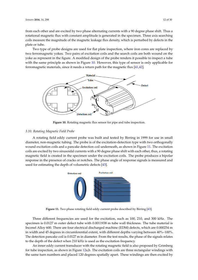
from each other and are excited by two phase alternating currents with a 90 degree phase shift. Thus arotational magnetic flux with constant amplitude is generated in the specimen. Three axis searchingcoils measure the magnitude of the magnetic leakage flux density, which is perturbed by defects in theplate or tube.
Two type of probe designs are used for flat plate inspection, where iron cores are replaced bytwo ferromagnetic yokes. Two pairs of excitation coils and the search coils are both wound on theyoke as represent in the figure. A modified design of the probe renders it possible to inspect a tubewith the same principle as shown in Figure 10. However, this type of sensor is only applicable forferromagnetic materials, since it needs a return path for the magnetic flux [41,42].
Figure 10. Rotating magnetic flux sensor for pipe and tube inspection.
3.10. Rotating Magnetic Field Probe
A rotating field eddy current probe was built and tested by Birring in 1999 for use in smalldiameter, non-magnetic tubing. The probe is of the excitation-detection type with two orthogonallywound excitation coils and a pancake detection coil underneath, as shown in Figure 11. The excitationcoils are excited by two sinusoidal currents with a 90 degree phase shift with each other, thus, a rotatingmagnetic field is created in the specimen under the excitation coils. The probe produces a bipolarresponse in the presence of cracks or notches. The phase angle of response signals is measured andused for estimating the depth of volumetric defects [43].
Figure 11. Two phase rotating field eddy current probe described by Birring [43].
Three different frequencies are used for the excitation, such as 100, 210, and 300 kHz. Thespecimen is 0.0127 m outer defect tube with 0.0011938 m tube wall thickness. The tube material isInconel Alloy 600. There are four electrical discharged machine (EDM) defects, which are 0.000254 min width and 45 degrees in circumferential extent, with different depths varying between 40%–100%.The detection pancake coil is 0.0127 m in diameter. From the test results, the phase of the signals relatesto the depth of the defect when 210 kHz is used as the excitation frequency.
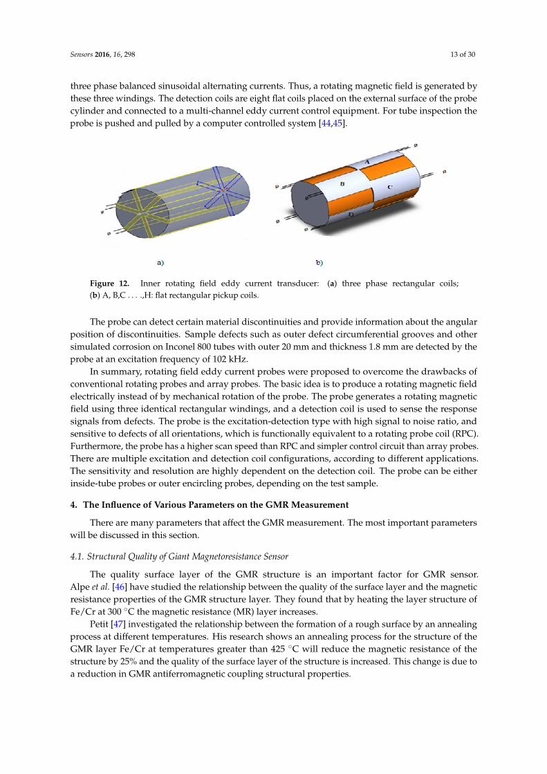
An inner eddy current transducer with the rotating magnetic field is also proposed by Grimbergfor tube inspection, as shown in Figure 12a,b. The excitation coils are three rectangular windings withthe same turn numbers and placed 120 degrees spatially apart. These windings are then excited by
Sensors 2016, 16, 298 13 of 30
three phase balanced sinusoidal alternating currents. Thus, a rotating magnetic field is generated bythese three windings. The detection coils are eight flat coils placed on the external surface of the probecylinder and connected to a multi-channel eddy current control equipment. For tube inspection theprobe is pushed and pulled by a computer controlled system [44,45].
Figure 12. Inner rotating field eddy current transducer: (a) three phase rectangular coils;(b) A, B,C . . . .,H: flat rectangular pickup coils.
The probe can detect certain material discontinuities and provide information about the angularposition of discontinuities. Sample defects such as outer defect circumferential grooves and othersimulated corrosion on Inconel 800 tubes with outer 20 mm and thickness 1.8 mm are detected by theprobe at an excitation frequency of 102 kHz.
In summary, rotating field eddy current probes were proposed to overcome the drawbacks ofconventional rotating probes and array probes. The basic idea is to produce a rotating magnetic fieldelectrically instead of by mechanical rotation of the probe. The probe generates a rotating magneticfield using three identical rectangular windings, and a detection coil is used to sense the responsesignals from defects. The probe is the excitation-detection type with high signal to noise ratio, andsensitive to defects of all orientations, which is functionally equivalent to a rotating probe coil (RPC).Furthermore, the probe has a higher scan speed than RPC and simpler control circuit than array probes.There are multiple excitation and detection coil configurations, according to different applications.The sensitivity and resolution are highly dependent on the detection coil. The probe can be eitherinside-tube probes or outer encircling probes, depending on the test sample.
4. The Influence of Various Parameters on the GMR Measurement
There are many parameters that affect the GMR measurement. The most important parameterswill be discussed in this section.
4.1. Structural Quality of Giant Magnetoresistance Sensor
The quality surface layer of the GMR structure is an important factor for GMR sensor.Alpe et al. [46] have studied the relationship between the quality of the surface layer and the magneticresistance properties of the GMR structure layer. They found that by heating the layer structure ofFe/Cr at 300 ˝C the magnetic resistance (MR) layer increases.
Petit [47] investigated the relationship between the formation of a rough surface by an annealingprocess at different temperatures. His research shows an annealing process for the structure of theGMR layer Fe/Cr at temperatures greater than 425 ˝C will reduce the magnetic resistance of thestructure by 25% and the quality of the surface layer of the structure is increased. This change is due toa reduction in GMR antiferromagnetic coupling structural properties.

Sensors 2016, 16, 298 14 of 30
4.2. Thickness Structure Layers of Giant Magnetoresistance Sensor
Parkin et al. [48] introduced in 1990 a sputtering technique in the fabrication process of GMRstructures. With this technique, the GMR structure growth process is fast compared to the MBE processand this enabled them to study the effects of spacer thickness on the magnetic resistance of GMRstructures. They proved there is coupling between the ferromagnetic and antiferromagnetic materialin GMR structures of Fe/Cr. When the thickness of the spacer in the Fe/Cr GMR structure is increased,the magnetic resistance of the structure began to change from infinite to zero. They found that themagnetic resistance properties decrease when the thickness of the Cu spacer increased, as shown inFigure 13.
Figure 13. Magnetoresistance versus Cu spacer thickness for Co/Cu GMR multilayers at roomtemperature by Parkin et al. [48].
A study by George et al. [49] demonstrated that the high magnetic resistance on Co/Cu GMRstructure layers is caused by the scattering effect of the electron spin in the surface layer of Co and Cu.They found that the effect of scattering occurs at the interface. They found that when the temperature ofthe Cu layer increased to 4.2 K, the magnetic resistance of the structure will be changed to a certain pointas shown in Figure 14 before it becomes almost horizontal when the thickness of this layer is 50 Å.
Figure 14. Variation of the MR ratio as a function of the Cu thickness by George et al. [49].
As a conclusion, the GMR layer structure should be optimized as possible for high magneticresistance properties. GMR layer structures should be thin, but not too thin to avoid a thick formationof pinholes.

Sensors 2016, 16, 298 15 of 30
4.3. Temperature
The effect of magnetic resistance decreases monotonically by a temperature factor between 1.5to 3 at a temperature between 4 K and room temperature. The increase in temperature increases thenumber of electrons scattering in NM layers, causing the number of electrons moving between thelayers of GMR structures to increase. This result reduces the efficiency of the GMR mechanism withincreasing temperatures.
In recent years, several studies have focused on the thermal stability of GMR structures and therelationship between temperature and magnetic resistance (MR) in GMR structures. To enhance thethermal stability of the GMR layer structure, Hossain et al. [50] proposed a GMR structure composedof NiFeCo/Cu layers. The layer structure is fabricated using a sputtering method and has a thickof the magnetic layer. Cu spacer thickness is set to 2.3 nm and a layer of magnetic material that ischanged from 1.7 nm up to 3.7 nm. Their observations show the structure of the layer thickness of3.7 nm NiFeCo shows good in thermal stability with high sensitivity, as shown in Figure 15.
Figure 15. GMR sensitivity in as-deposited (ASD) and annealed (ANN) states as a function of theNiFeCo layer thickness by Hossain et al. [50].
In a different study, A. iritaratiwat at el. [51] investigated the effect of the annealing process onthe NiFe/Cu layer of a GMR structure. The thickness of the NiFe layer is 2.5 nm and the Cu spacer is5 nm. They heat the GMR structure for 2.5 h at 300 ˝C, 325 ˝C and 350 ˝C in a vacuum chamber. In asecond experiment, they heat the GMR structure with same experimental parameter settings but witha stream medium of argon gas. The results are shown in Figure 16.
Figure 16. The annealed GMR multilayer in a vacuum at 300 ˝C, 325 ˝C and 350 ˝C. by Siritaratiwat et al. [51].

Sensors 2016, 16, 298 16 of 30
As shown in Figure 17, when a GMR structure is heated at a temperature (300 ˝C, 325 ˝C and350 ˝C) under vacuum conditions there is an improvement in the structure of the magnetic resistanceup to 1%, while the GMR heated in flowing argon medium has improved magnetic resistance MRstructure properties by up to 2.5%.
Figure 17. Annealed GMR multilayer in flowing argon by Siritaratiwat et al. [51].
5. Factors Affecting the Eddy Current Testing Inspection
Many factors, other than defects and cracks, will influence the eddy current inspection. Thesignal from an eddy current probe is a compilation of responses, including responses from flaws anddefects, sample geometry, and probe lift-off [52–54]. Therefore, it might be hard to isolate a singleeffect. Successful evaluation of flaws or any other surface properties is possible when the other factorsare known. The main factors affecting the coil response are:
5.1. Exciting Coil Frequency and skin Depth Effect
The capabilities of conventional eddy current testing using a single frequency current coilexcitation are limited to detecting defect depth in one or two skin depths. Multi-frequency excitationcoil eddy current testing was introduced to obtain additional different depth defect profile information.Sine wave current excitation coils with frequencies between 100 Hz up to a few MHz are used to checkprofile material defects in different layers [55,56].
The exciting coil frequency is a very important factor in determining the depth of the locateddefect. For subsurface defect inspection, a low frequency will be applied [57]. On the other hand, fordetecting surface defects, a high frequency needs to be applied. Table 2 summarizes the values of skindepth for several materials at different frequencies.
Eddy current density in metallic materials decreases exponentially in proportion to the depth ofthe material. The standard penetration of eddy currents is where the strength of the eddy current is37% of the strength of the eddy current on the surface of the material [58]. Apart from the frequencycurrent coil, the penetration depth of eddy current depends on the the electrical conductivity andpermeability properties of the material tested. Depth penetration of the eddy current in the materialcan be calculated using the following formula [59,60]:
δ “1
a
π f µσ(1)
where δ: Skin depth (mm); f : Excitation frequency of the coil; µ: conducting material permeability andσ: conducting material conductivity. As the magnitude of the eddy current decreases exponentially
Sensors 2016, 16, 298 17 of 30
with the depth of the tested material, the amplitude of the magnetic field along the X-axis generatedby the eddy current in the material under test can be represented by the following formula [61,62]:
J pxq “ JsXe´xδ (2)
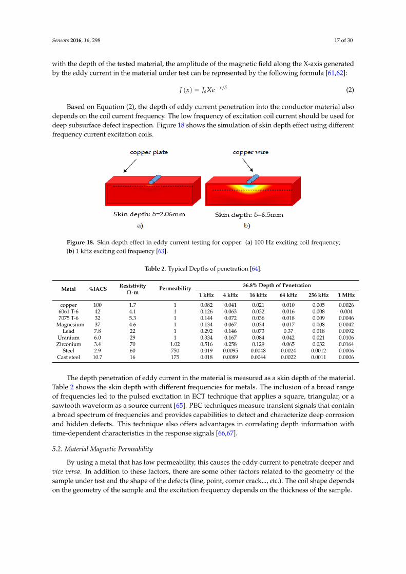
Based on Equation (2), the depth of eddy current penetration into the conductor material alsodepends on the coil current frequency. The low frequency of excitation coil current should be used fordeep subsurface defect inspection. Figure 18 shows the simulation of skin depth effect using differentfrequency current excitation coils.
Figure 18. Skin depth effect in eddy current testing for copper: (a) 100 Hz exciting coil frequency;(b) 1 kHz exciting coil frequency [63].
Table 2. Typical Depths of penetration [64].
Metal %IACS Resistivity٨m
Permeability 36.8% Depth of Penetration
1 kHz 4 kHz 16 kHz 64 kHz 256 kHz 1 MHz
copper 100 1.7 1 0.082 0.041 0.021 0.010 0.005 0.00266061 T-6 42 4.1 1 0.126 0.063 0.032 0.016 0.008 0.0047075 T-6 32 5.3 1 0.144 0.072 0.036 0.018 0.009 0.0046
Magnesium 37 4.6 1 0.134 0.067 0.034 0.017 0.008 0.0042Lead 7.8 22 1 0.292 0.146 0.073 0.37 0.018 0.0092
Uranium 6.0 29 1 0.334 0.167 0.084 0.042 0.021 0.0106Zirconium 3.4 70 1.02 0.516 0.258 0.129 0.065 0.032 0.0164
Steel 2.9 60 750 0.019 0.0095 0.0048 0.0024 0.0012 0.0006Cast steel 10.7 16 175 0.018 0.0089 0.0044 0.0022 0.0011 0.0006
The depth penetration of eddy current in the material is measured as a skin depth of the material.Table 2 shows the skin depth with different frequencies for metals. The inclusion of a broad rangeof frequencies led to the pulsed excitation in ECT technique that applies a square, triangular, or asawtooth waveform as a source current [65]. PEC techniques measure transient signals that containa broad spectrum of frequencies and provides capabilities to detect and characterize deep corrosionand hidden defects. This technique also offers advantages in correlating depth information withtime-dependent characteristics in the response signals [66,67].
5.2. Material Magnetic Permeability
By using a metal that has low permeability, this causes the eddy current to penetrate deeper andvice versa. In addition to these factors, there are some other factors related to the geometry of thesample under test and the shape of the defects (line, point, corner crack..., etc.). The coil shape dependson the geometry of the sample and the excitation frequency depends on the thickness of the sample.

Sensors 2016, 16, 298 18 of 30
5.3. Lift-off
Lift-off is the distance between the probe eddy current testing (exciting coil and receiving sensor)and the surface of the conducting specimen under test. When lift-off increases, the secondarymagnetic field on the specimen surface decreases, which causes reduced sensitivity of the probe.Dogaru et al. [68] investigated the lift-off as a function of the GMR sensor amplitude output signal.Figure 19 show the peak amplitude of an output voltage GMR sensor changes with the lift-off distance.
Figure 19. A peak amplitude as a function of lift-off distance between probe and specimen surface.
5.4. Conductivity of Material
When the conductivity changes, the magnetic field changes too, and this affects the output of thereceiving magnetic sensor on the probe. The conductivity of metals is affected by heat treatment, agehardening temperature, chemical deposition and residual stresses. The conductivity is measured byreferring to the International Annealed Copper Standard (IACS). Table 3 summarizes the conductivityand resistivity of selected conductive materials (Moulder et al. [69]).
Table 3. Conductivity and resistivity of conductive materials.
Material Conductivity (% IACS) Resistivity (µΩ/cm)
Aluminum bronze 14.00 12.32Aluminum 7075-T6 32.00 5.39Aluminum 2024-T4 30.00 5.20
Aluminum 6061 42.00 4.10Brass 28.00 6.20
Copper nickel 70–30 4.60 37.48Copper 100.00 1.72
Gold 70.00 2.46Monel 3.60 47.89
Copper nickel 90–10 9.10 18.95Cast Steel 10.70 16.02
Hastelloy-X 1.50 115.00Inconel 600 1.72 100.00
Lead 8.35 20.65Magnesium 38.60 4.45
Phosphor bronze 11.00 16.00Silver 105.00 1.64
Stainless Steel 316 2.33 74.00Stainless Steel 304 2.39 72.00
Sodium 41.50 4.20Ti-6AI-4V 1.00 172.00
Titanium-2 3.55 48.56Tungsten 30.51 5.65
Zirconium 4.30 40.00Zircalloy-2 2.40 72.00

Sensors 2016, 16, 298 19 of 30
5.5. Limitations of Coil Sensor in Eddy Current Probe
Traditional EC methods use coils as sensors (pick-up coils) to measure changes in the magneticfield. Based on Faraday’s law of induction, the voltage response of a pick-up coil is proportional to therate of change of the induced magnetic field not the magnetic field itself. Therefore, it results in poorSNR ratio particularly at low frequencies [66,70]:
Vcoil signal “ Nπr2 dBdt9Nπr2 f (3)
where N is the number turns of coil wire, πr2 is the area of the loops and dB/dt is the rate of change ofmagnetic field that is proportional to the operating frequency f.
Consequently, coil sensors are fundamentally limited by their poor sensitivity at low frequencies.Unfortunately, sensitivity at low frequency is needed in the inspection of thick components andsubsurface flaws. Similar to traditional coils, planar coils also present limited sensitivity when they areused as pick-up or inductive coils for sensing low-frequency magnetic fields [71]. Alternately, ECTprobes that are operated in hybrid mode have been developed to overcome those limitations. As shownin Figure 20, hybrid ECT techniques employ conventional or planar coils to generate eddy currents andutilize magnetic field sensors to directly measure field variations associated with discontinuities [26,72].
Figure 20. Hybrid probe [26,72]: ECT coil with magnetic field sensor.
6. Compensation Techniques in Eddy Current Testing Probes
Many factors affect the accuracy of defect measurement using the eddy current testing technique.Factors such as temperature, hysteresis, edge effect and lift-off should be considered for accurateinspection. Several researchers have focused on solving and compensating the factors that affect theeddy current measurement. Based on the 3D Helmholtz coil, Jixi et al. [73] have developed a specialsystem for testing characteristics of a GMR sensor. They used a series resonance circuit to compensatethe increase of inductive impedance when the frequency of the exciting coil increases. Experimentsshowed the precision of GMR sensor measurement increased if the density of the magnetic fieldwas in the linear measurement range. However, the error is still high with a percentage of 20% dueto hysteresis effects on the GMR sensor output signal. Pelkner et al. [74] analyzed the optimumconfiguration of a GMR sensor array for optimum defect inspection. They analyzed the magnetic fluxdistribution (MFL) model to represent multi-sensor function parameters. Their test results showedthat a sensor array arranged in a configuration of half bridges and Wheatstone bridges can minimizethe effect of temperature on GMR sensor array measurements.
Lift-off is the main factor in ECT signal reading errors. The lift-off may be described as thedistance between the probe and the test piece. Its variation adversely affects the ECT inspection inmany applications [75] so it is therefore considered as the main noise factor in ECT signal analysis. Toavoid lift effect the probe distance with the test piece should be maintained, but in a real application, itis difficult because of factors such as irregular test surfaces, varying coating/lagging thicknesses andoperator movement [76].
To compensate lift-off effect, Yin et al. [75] published a research finding on an analytical modelbased on multi-frequency excitation and coil design aimed at the reduction of this effect. Their

Sensors 2016, 16, 298 20 of 30
findings showed that the phase spectra of such coil designs are essential to remove the lift-off invariant.Xu et al. optimized an ECT coil design in an attempt to reduce lift-off effects [77]. In a different studyLopez et al. [78] proposed a wavelets technique to remove noise from probe wobble in steam generatortube inspection. A normalization technique has been proposed by Tian et al. [79] to minimize lift-offeffects. They demonstrated it could be used in metal thickness measurement under non-conductivecoatings and for microstructure analysis where the output signal is affected by the presence of lift-offeffects. In another study, Fan et al. [80] has presented a lift-off analytical model for probe wobble in heatexchanger tube inspection. Another way of dealing with this effect is by using invariant point featurescalled lift-off point of intersections, which has been successfully used to estimate the conductivity oftest materials in [76] and for corrosion mapping in gas pipelines [81].
When an eddy current testing probe is at the end of a specimen, a edge effect phenomenon setsin. At the edge of test piece the eddy current in the test piece is distorted as the current cannot flow.In order to avoid it being mistaken for a defect signal, Yang et al. [82] suggested small probes shouldbe used for defect inspection near edges. They developed a post-processing subtraction algorithm tocompensate for the edge signal effect. In contrast, Theodoulidis et al. [83,84] proposed a mathematicalmodel to calculate the field of a coil probe on the edge of a conductive material. This model elicitedsome analytical field formulations that gave better insight into this phenomenon and could formthe basis of a process for solving edge effect-associated challenges. Table 4 provides a summary ofcompensation techniques used in eddy current testing probes.
Table 4. Compensation techniques used in eddy current testing.
Ref. Research Area Compensation Techniques
[85] To remove the lift-off effect in PEC ferromagnetic materialtest piece inspection Relative magnetic flux changing rate
[86] Presented a simple model for metal thickness measurementthat unaffected by lift-off effect.
Signal analysis base on multi-frequencyphase signature
[87] Developed ECT system based on three coils exciting coils tomeasure the plate thickness
Data analysis using peak frequencies of the sensorsignal to estimate the thickness of the plate
[88] Proposed a method for suppressing of lift-off effect inSMFM system Signal deconvolution
[89]Proposed ECT system with rectangular sensorconfiguration and time domain analysis and frequencydomain analysis for defect classification.
Time domain analysis and frequencydomain analysis
[90] Proposed a method to reduce the lift-off effect in PEC deepdefect measurement
Measure the defect dimension base on slope of thelinear curve of the peak value differencesensor signal
[91] Investigate the lift-off effect in the normalizedimpedance plane Hough transform
[92] Developed PECT system for ferromagnetic materialelectrical conductivity measurement Mathematical model
[89] Investigated the feature extraction techniques for PECdefect classification Signal differential analysis
[93] Developed ECT system to measure the thickness ofnickel layer 3-D edge-based hexahedral nonlinear FEM
[79] Investigated the effect of lift –off in PECnon-destructive testing Normalization and two-stage operative process
[94] Construct a system to measure the thickness of metal plates Lift-off points of interception
7. Application of GMR Sensors in Hybrid Eddy Current Testing Probes
Implementation of the GMR sensor as a magnetic receiver in eddy current testing probes hasshown significant improvement in term of efficiency in defect inspection. Conventional eddy currentprobes using a coil as a magnetic detection cause the noise ratio of the defect signal to be high and thiscauses the accuracy of defect interpretation to be inaccurate. GMR magnetic sensors directly measure

Sensors 2016, 16, 298 21 of 30
the magnetic field changes and this increases the sensitivity of the probe in detecting a subsurfacedefect that is far below the tested surface material. For this reason, the study of the application of GMRsensors in non-destructive testing remains the focus of researchers.
Postolache et al. [58] developed an eddy current testing system using GMR sensors to detect andmeasure the size of defects on aluminum plates. They used various different frequency excitationsystems and processing methods, and a neural network to classify the size of the detected defects.Initial tests showed their system can detect and classify types of defects within a limited range ofdefects. This system can be improved by optimizing the detection and classification system. Jedlicskaand Weigel [95] introduced a method for increasing the GMR sensor measurement accuracy byeliminating hysteresis effects in GMR sensor output signals. A mathematical model of hysteresis wasimplemented in an eddy current testing system based on a GMR sensor. The system is fully controlledby LABVIEW software. Comparison of simulation results with experimental results showed significantresults. However, these systems do not consider other factors in eddy current testing such as materialpermeability properties and temperature effects on measurement. Meanwhile, Bernieri and Betta [96]introduced measurement and calibration procedures for GMR sensors to reduce the effect of hysteresisand nonlinearity. They introduces procedures to improve the accuracy of the reading in DC and ACexcitation magnetic fields up to 98.2% and 99.4%.
In different studies, Winncy et al. [97] have designed a robot for internal pipe defect inspection.The sensor array consists of four GMR sensors which have high sensitivity (0.9 to 1.3 mg/V). Thesensor housing is made using a polycarbonate material to minimize the disturbance on the magneticfield. Four GMR sensors are arranged at a uniform distance and a PIC microcontroller is used asthe main controller and data processing system. Permanent magnets are used to generate magneticfields. A Fast Fourier transform is used to differentiate the defect signals. Their experiments showedthat different types of defect generate different harmonic signals. However, the use of permanentmagnets to generate the magnetic field limits their depth of defect detection. Yang et al. [98] used aGMR sensor to investigate the quality of aeronautical structures. The focus of their study was thedefects under the riveted headings used to connect the airplane wing structure. The exciting rotatingmagnetic field is used to enable the GMR sensor to show a uniform sensitivity. Mathematical modelingand experimental validation were conducted to show how the different defects give different signals.However, this study could be improved by using an array of GMR sensors to obtain clear structuredefects. Meanwhile, Gao et al. [99] used the amplitude-phase of the GMR sensor output signal toclassify the type of defect. Their experimental results show that defect classification is more accurateusing the analysis of the phase signal of the GMR sensor output.
GMR sensors have been used in eddy current testing to measure the depth of cracks in thestructure of airplanes by Pasadas et al. [100]. A high-density magnetic field is applied to the entirecracked structure. Features of 2-D defects were successfully obtained with accurate dimension ofdefect information. Chao et al. [101] have been integrating GMR sensors with Field ProgrammableGate Arrays (FPGAs) for the development of eddy current nondestructive testing systems which candetect cracks up to 10 mm wide. Through a series of experiments, they proved the characteristics ofthe phase signal output of the GMR sensor can provide more accurate defect information compared toamplitude signal analysis.
For detailed defect profiling, five GMR sensors were integrated into a eddy current testing systemby Postolache et al. [58]. Excitation of the uniform magnetic field is generated by using alternatingcurrent and direct current sources. The system works automatically, which can give a defect in theform of a 2-D image. Meanwhile Munoz et al. [102] constructed their eddy current probe using a GMRsensor and a permanent magnet for exciting a magnetic field. They studied the relationship betweenthe orientation of defects with the sensor GMR output signal. Iron plates with two-dimensional defectdepths of 0.5, 1.0, 1.5, 2.0, 2.5 and 3.0 mm and a width of 0.25 and 0.5 mm were fabricated to test theprecision of the probe. The experiments showed the signal output of GMR is sensitive to the orientation

Sensors 2016, 16, 298 22 of 30
of defects. Table 5 summarizes previous studies that applied GMR sensors in non-destructive eddycurrent testing.
Table 5. Summary of previous studies on application of GMR sensor in eddy current testing.
Author Reseach Area Signal Analysis Tool/SoftwareSimulation Observations
[103] Defect classification in aluminiumplate test pieces Neural Network Processing
Probe optimization and defectclassification using limiteddefect features.
[95]To increase the accuracy of theGMR sensor by numericallycompensating the hysteresis effect
Finite Impulse ResponseStrongly reduced the hysteresis andoptimized the probe design byincreasing the speed of inspection
[104]Optimize the eddy current testingprobe for subsurface tiny crackdefect inspection
Maxwell design simulation
The system is able to detect tiny defectcracks of up to 3 mm under thesurface. Experimental results provethe main source of noise is the currentexcitation frequency.
[97]Developed an eddy current testingprobe based on an array of GMRsensors for pipe inspection
Fast Fourier Transformation
The array of GMR sensors is able todetect various types of defect. Thesignal output of the array sensor canbe used to classify and define theproperties of different defects.
[105]
Designed and construct anautomatic eddy current system forinspection of an artificial straightdefect in an aluminium plate.
Neural network/multilayerperceptron/competitive neuralnetwork/finite elementsimulation
Implementation of the neural networkclassification technique increases theaccuracy of defect classification
[106]
Designed and developed an eddycurrent testing probe using arotating exciting magnetic field fordetection of radial cracks around afastener
Finite element model simulation
The eddy current testing probe currentshift exciting magnetic field is 90˝ inphase. The simulation andexperimental results show the systemis able to detect all orientations of adefect under the fastener
[107]Developed an ECT system toclassify multiple classes of defectthickness in conductive plates.
Support vector machine—SVMThe system successfully classified thethickness defect with an error lowerthan 1.52%.
[99]Investigated the defect propertiesbased on the phase signal of aGMR sensor
Finite element method(FEM) program
The experimental results proved thephase signal output of the GMR sensorprovides more defect information.
[108] Developed an ECT probe forsurface defect inspection. -
The probe was able to detect andmeasure an artificial defect with adimension of 0.15 mm width and0.2 mm depth.
[100]
Investigated the efficiency ofdefect detection using adifferential pick-up coil and GMRsensor
-
Both sensors were able to detectdefects with thicknesses of more than1 mm. The GMR sensor detects thedefect when the sensing directioncrosses the edge defect while thepick-up coil needs the whole magneticfield to cross the defect to detect it.
[109]
Designed a 2-D magnetic fieldcamera system to measure theproperties of the magnetic fieldaround inner and outer defects ina piping system
-The system is able to sense themagnetic field in the radial andaxial direction.
[110] Proposed a method for deepsubsurface defect inspection. Finite Element Method (FEM)
Experimental and simulation show thesystem is able to detect deepsubsurface defects
[111]Investigated defect signals of anartificial rectangular straightdefect in aluminium plates.
-The experiments showed the directionof the defect is easy to detect if thedefect is crossing the magnetic field.

Sensors 2016, 16, 298 23 of 30
Table 5. Cont.
Author Reseach Area Signal Analysis Tool/SoftwareSimulation Observations
[101]
Designed an ECT system based ona GMR sensor and a FieldProgrammable Gate Array (FPGA)as controller
Fourier Transform analysis
The system able to display the defectsignals in amplitude and phase mode.A signal demodulation function hasbeen realized for defectcharacteristic analysis.
[96]
Developed a low-cost ECT systemwith an automatic calibrationsystem to reduce the uncertaintyof GMR sensor measurement.
Static (DC) and dynamic (AC)analysis
The system is capable of inspectingdefects using DC and AC excitingmagnetic fields with a high percentageof accuracy
[112]Developed an ECT system basedon a GMR sensor for surfacedefect inspection
Polynomial regression
The system scans the defect in thedirection of the sensor sensitivescanning area foraccurate measurement.
[58]
Designed and optimized an ECTprobe based on two planarexcitation coils and a rectangularmagnetic field biasing architecture
LabVIEW/sum squareddifference (SSD) and normalizedcross correlation (NCC)
Improved the inspection capabilities ofthe ECT probe with fast scanning time
[102] Developed an ECT probe withradial magnetization -
The 50˝ angle axis sensitivity of theGMR sensor to the defect orientationreduces by 28% the average value ofthe VD parameter
[113]
Investigated the performance ofmagnetic detection in an ECTprobe for non-destructiveinspection.
Numerical simulationsThe results show a GMR sensor isbetter compared to the coil detector interm of sensitivity and dimensions.
[114]Designed and modeled a magneticfield based on guidemagnetic slopes
Finite element method (FEM)The experimental results show theGMR sensor is sensitive only to thez-component of the magnetic field.
[94]Implementation of an ECT tomeasure the thickness ofmetallic plates
-
The experiments show a frequency of250 Hz is the optimum excitation coilfrequency for maximum depthmagnetic field penetration in themetal plate
[115] Developed an ECT inspectionsystems using a GMR sensor -
The system has the ability to inspectsubsurface cracks at frequencies lowerthan 3.3 kHz
[74]Investigated the optimalarrangement of a GMR sensor foroptimum defect inspection.
Analytical model
The analysis shows the length andheight of the GMR sensor influencesignal strength loss by up to 10% a in250 µm defect baseline
[116]
Investigated the characteristics ofthe current around an artificialcrack for defectgeometry identification
Fast Fouriertransform/Tikhonovregularization algorithm
Characteristics of the current show asignificant pattern with differentgeometry of cracks.
[98]
Proposed a novel invarianceanalysis for ECT signals in deepsubsurface defects underfastener heads
Finite Element (FE)
Presented a reliable ECT inspectiontechnique for different sizes andgeometries of cracks underfastener heads.
[117]Proposed an ECT system forinspection of hiddencorrosion defects.
FEMThe inspection results show highaccuracy with mean errors ofless than 2%
[118] Developed a PEC–GMR systemfor ECT non-destructive testing
Principal component analysisand the k-means algorithm
The system is capable of detectingcracks with a size of 1 mm located upto 10 mm subsurface
[119]Developed an ECT–NDT systembased on (GMR) sensors for circuitboard (PCB) inspection
COMSOL Multiphysics
The system is capable of detecting andcharacterizing the type of defect tracknarrowing, circular holes andtrack dilatation.

Sensors 2016, 16, 298 24 of 30
Table 5. Cont.
Author Reseach Area Signal Analysis Tool/SoftwareSimulation Observations
[120]
Developed a general procedure forECT defect sizing andclassification inmultilayered structures
Partial least squares(PLS)/kernel partial leastsquares (KPLS)
The KPLS regression method gives abetter prediction performancecompared to the PLSregression method
[121]Proposed a novel ECT techniquebased on the induced velocity ofeddy currents
Numerical modelThe proposed method increases thesensitivity and the depth defectdetection of the system.
[122]
Investigated the optimumasymmetrical coil-GMRconfiguration for surfacedefect inspection
-
The experimental resultsdemonstrated that the intermediatepeak does not have any influence onDV value with the depth of defects
[123]Analyzed the sensitivity of GMRsensors and GMI sensors indetecting the magnetic field
Finite Element/Momentsanalysis
The experimental and modelingresults show the GMR and GMIsensors are able to detect the changesof orientation of a magnetic fieldexcited by using AC and DCcurrent sources
[54]Investigate the effect of lift-off inmetallic plate thicknessmeasurement
Linear TransformerModel/experimental
The lift-off, material conductivity andthe plate thickness have a significantinfluence on the measurement ofmetallic plate thickness
[124]Developed an ECT system basedon a GMR sensor array for outersteel rope track defect inspection.
Finite element model
The experimental results reveal thatthe ECT system is able to detect bothof LF and LMA type defects in therope track.
[55]Proposed a novel design of arotating magnetic field ECT forSG tubes.
Finite Element modeling
The simulation and experimentalresults show that the probe is sensitiveto defects in ferromagnetic andnon-ferromagnetic tubes.
[125]Investigated the performance ofthe PEC technique in materialthickness measurement
Experimental
The method was verifiedexperimentally to be suitable formaterial thickness measurement sincethe PEC method has deepmagnetic penetration.
[126]Enhanced the sensitivity of theECT-GMR system using analysisof two signal GMR sensors
(3-D) Finite Element Mesh
Simulation results show that theproposed method improvedsignificantly the sensitivity of thesystem in detection of multilayersubsurface defects
[127]Developed an ECT-GMR systemfor inspection of defects underfasteners in airframe structures
Time domain and frequencydomain features
Experimental results demonstrate thefeasibility of the proposed approachfor the detection of simulated cracks(less than 1 mm length) that are buried4 mm deep in the second layer
8. Conclusions
The eddy current testing technique has played an important role as one of the mainnon-destructive techniques chosen by industry. The reliability of the ECT technique in an inspection ofthe material quality was proven to show better capability in defect detection. Although it shows greatadvantages compared to other non-destructive methods, the eddy current technique has a particulardrawback that originates from its underlying principles, however the implementation of GMR sensorsin eddy current testing probe designs overcomes the weakness and limitations of non-destructive eddycurrent testing inspection. Implementation of GMR sensors in ECT probe design significantly increasesthe measurement accuracy and scope of the inspections possible using ECT techniques.
Lift-off and edge effects are the main factors affecting the ECT signal causing erroneous datainterpretation. The evolution of simulation software and the intelligent algorithms has led to various

Sensors 2016, 16, 298 25 of 30
analytical solutions that can thus compensate the unwanted signals, promising a more comprehensivedefect profile analysis and unambiguous resolution of deep hidden defects in thick structures.
Acknowledgments: This work was supported by the TATI University College under grant number 9001-1501and University Malaysia Pahang under project vote GRS 150391.
Author Contributions: Damhuji Rifai and Ahmed N. Abdalla designed and arranged the structure of the article;Kharudin Ali and Ramdan Razali review the previous work in this field; Damhuji Rifai and Ahmed N. Abdallawrote the paper.
Conflicts of Interest: The authors declare that there is no conflict.
Abbreviations
The following abbreviations are used in this manuscript:
NDT Non-destructive testingECT Eddy current testingGMR Giant magnetoresistanceMR MagnetoresistanceAFM AntiferromagneticFM FerromagneticRPC Rotating pancake coilDAQ Data acquisition,NM Non-magneticFEM Finite element methodAC Alternating currentDC Direct current
References
1. Ghoni, R.; Dollah, M.; Sulaiman, A.; Ibrahim, F.M. Defect Characterization Based on Eddy Current Technique.Tech. Rev. 2014, 6. [CrossRef]
2. Li, W.; Chen, G.; Yin, X.; Zhang, G.; Liu, T. Analysis of the lift-off effect of a U-shaped ACFM system.NDT&E Int. 2013, 53, 31–35.
3. He, Y.; Pan, M.; Luo, F.; Tian, G. Pulsed eddy current imaging and frequency spectrum analysis for hiddendefect nondestructive testing and evaluation. NDT&E Int. 2011, 44, 344–352.
4. Biju, N.; Ganesan, N.; Krishnamurthy, C.V.; Balasubramaniam, K. Optimum frequency variations with coilgeometry and defects in tone burst eddy current thermography (TBET). Insight Non-Destr. Test. Cond. Monit.2013, 55, 504–509. [CrossRef]
5. Abidin, I.; Umar, M.; Yusof, M. Advantages and Applications of Eddy Current Thermography Testingfor Comprehensive and Reliable Defect Assessment. In Proceedings of the 18th World Conference onNondestructive Testing, Durban, South Africa, 16–20 April 2000.
6. Current, A.E.; Principle, T. Eddy Current Crack Extension Direction Evaluation based on Neural Network.In Proceedings of the 2012 IEEE conference on Sensors, Taipei, Taiwan, 28–31 October 2012; pp. 3–6.
7. Hellier, C.J. Hanbook of Nondestructive Evaluation; McGraw-Hill Education: New York, NY, USA, 2012.8. García-Martín, J.; Gómez-Gil, J.; Vázquez-Sánchez, E. Non-destructive techniques based on eddy current
testing. Sensors 2011, 11, 2525–2565. [CrossRef] [PubMed]9. Poon, T.Y.; Tse, N.C.F.; Lau, R.W.H. Extending the GMR current measurement range with a counteracting
magnetic field. Sensors 2013, 13, 8042–8059. [CrossRef] [PubMed]10. Obeid, S. Giant Magnetoresistance Sensing Technologies for Detecting Small Defects in Metallic Structures.
Ph.D. Thesis, University North Carolina, Chapel Hill, NC, USA, 2008.11. Jogschies, L.; Klaas, D.; Kruppe, R.; Rittinger, J.; Taptimthong, P.; Wienecke, A.; Rissing, L.; Wurz, M.
Recent Developments of Magnetoresistive Sensors for Industrial Applications. Sensors 2015, 15, 28665–28689.[CrossRef] [PubMed]
Sensors 2016, 16, 298 26 of 30
12. Mott, N.F. The Electrical Conductivity of Transition Metals. Proc. R. Soc. London Ser. A Math. Phys. Sci. 1936,153, 699–717. [CrossRef]
13. Baibich, M.N.; Broto, J.M.; Fert, A.; van Dau, F.N.; Petroff, F.; Etienne, P.; Creuzet, G.; Friederich, A.;Chazelas, J. Giant magnetoresistance of (001)Fe/(001)Cr magnetic superlattices. Phys. Rev. Lett. 1988, 61,2472. [CrossRef] [PubMed]
14. Dieny, S.N.B.; Speriosu, V.S.; Gurney, B.A.; Parkin, S.S.P.; Wilhoit, D.R.; Roche, K.P.; Metin, S. Spin-valveeffect in soft ferromagnetic sandwiches J. Magn. Magn. Mater. 1991, 93, 101–104. [CrossRef]
15. Prinz, G.A. Magnetoelectronics. Science 1998, 282, 1660–1663. [CrossRef] [PubMed]16. Nogués, J.; Schuller, I.K. Exchange bias. J. Magn. Magn. Mater. 1999, 192, 203–232. [CrossRef]17. Freitas, P.P.; Silva, F.; Oliveira, N.J.; Melo, L.V.; Costa, L.; Almeida, N. Spin valve sensors. Sens. Actuators A
Phys. 2000, 81, 2–8. [CrossRef]18. Nolting, F.; Scholl, A.; Stohr, J.; Seo, J.; Fompeyrine, J.; Siegwart, H.; Locquet, J.; Anders, S.; Luning, J.;
Fullerton, E.; et al. Direct observation of the alignment of ferromagnetic spins by antiferromagnetic spins.Nature 2000, 405, 767–769. [CrossRef] [PubMed]
19. Kools, J.C.S. Exchange-biased spin-valves for magnetic storage. IEEE Trans. Magn. 1996, 32, 3165–3184. [CrossRef]20. Lenssen, K.M.H.; Adelerhof, D.J.; Gassen, H.J.; Kuiper, A.E.T.; Somers, G.H.J.; van Zon, J.B.A.D. Robust giant
magnetoresistance sensors. Sens. Actuators A Phys. 2000, 85, 1–8. [CrossRef]21. Parkin, S.S.P. Giant Magnetoresistance in Magnetic Nanostructures. Annu. Rev. Mater. Sci. 1995, 25, 357–388.
[CrossRef]22. Tsymbal, E.Y.; Pettifor, D.G. Perspectives of giant magnetoresistance. Solid State Phys. Adv. Res. Appl. 2001,
56, 113–237.23. Daughton, J.; Brown, J.; Chen, E.; Beech, R.; Pohm, A.; Kude, W. Magnetic field sensors using GMR multilayer.
IEEE Trans. Magn. 1994, 30, 4608–4610. [CrossRef]24. Vieux-Rochaz, L. A new GMR sensor based on NiFe/Ag multilayers. Sens. Actuators A Phys. 2000, 81, 53–56.
[CrossRef]25. Lee, J.; Jun, J.; Kim, J.; Choi, H.; Le, M. Bobbin-Type Solid-State Hall Sensor Array With High Spatial
Resolution for Cracks Inspection in Small-Bore Piping Systems. IEEE Trans. Magn. 2012, 48, 3704–3707.[CrossRef]
26. Cápová, M.S.K.; Cáp, I.; Janoušek, L. Recent trends in electromagnetic non-destructive sensing. Adv. Electr.Electron. Eng. 2008, 7, 322–325.
27. Popa, R.C.; Miya, K.; Kurokawa, M. Optimized eddy current detection of small cracks in steam generatortubing. J. Nondestruct. Eval. 1997, 16, 161–173. [CrossRef]
28. Bernieri, A.; Betta, G.; Rubinacci, G.; Villone, F. A measurement system based on magnetic sensors fornondestructive testing. IEEE Trans. Instrum. Meas. 2000, 49, 455–459. [CrossRef]
29. Kim, Y.-Y.; Lee, S.-S. Eddy current probes of inclined coils for increased detectability of circumferential cracksin tubing. NDT&E Int. 2012, 49, 77–82.
30. Lei, N.; Udpa, L.; Udpa, S.; Zeng, Z. Rotating field eddy current (RoFEC)-probe for steam generatorinspection. Int. J. Appl. Electromagn. Mech. 2010, 32, 1279–1285.
31. Thirunavukkarasu, S.; Rao, B.P.C.; Jayakumar, T.; Raj, B. Techniques for processing remote field eddy currentsignals from bend regions of steam generator tubes of prototype fast breeder reactor. Ann. Nucl. Energy 2011,38, 817–824. [CrossRef]
32. Obrutsky, L.S.; Sullivan, S.P.; Cecco, V.S. Transmit-Receive Eddy Current Probes. Available online:https://www.iaea.org/inis/collection/NCLCollectionStore/_Public/29/057/29057175.pdf (accessed on 18November 2015).
33. Sullivan, S.P.; Cecco, V.S.; Obrutsky, L.; Lakhan, R. Validating Eddy Current Array Probes for InspectingSteam Generator Tubes. NDTnet 1998, 3, 29–35.
34. Diercks, D. Steam generator tube integrity program. Nucl. Eng. Des. 1996, 165, 143–149. [CrossRef]35. Zaoui, A.; Menana, H.; Feliachi, M.; Berthiau, G. Inverse problem in nondestructive testing using arrayed
eddy current sensors. Sensors 2010, 10, 8696–8704. [CrossRef] [PubMed]36. Xie, R.; Chen, D.; Pan, M.; Tian, W.; Wu, X.; Zhou, W.; Tang, Y. Fatigue Crack Length Sizing Using a Novel
Flexible Eddy Current Sensor Array. Sensors 2015, 15, 32138–32151. [CrossRef] [PubMed]37. Jun, J.; Lee, J. Nondestructive evaluation of a crack on austenitic stainless steel using a sheet type induced
current and a Hall sensor array. J. Mech. Sci. Technol. 2009, 22, 1684–1691. [CrossRef]

Sensors 2016, 16, 298 27 of 30
38. Huo, S.; Wang, C.; Cheng, S.; Song, X. Impedance analyzing for planar eddy current probe array. InProceedings of the International 2011 Conference on Information Science and Technology (ICIST), Nanjing,China, 26–28 March 2011; pp. 995–999.
39. Heida, J.H.; Derk, J.P. Evaluation of non-destructive inspection methods for composite aerospace structures.NDT Prog. 2011, 2011, 1–12.
40. Panayiotou, S.; Soper, A. Artificially intelligent 3D industrial inspection system for metal inspection. InProceedings of the IEEE Southwest Symposium on Image Analysis and Interpretation, Dallas, TX, USA,21–24 April 1994; pp. 130–135.
41. Translation, I.; On, J.; In, M. Non-Destructive Testing with Magnetic Sensor Using Rotational Magnetic Flux.IEEE Trans. J. 1992, 7, 241–249.
42. Enokizono, M.; Todaka, T.; Akita, M. Rotational Magnetic Flux Sensor with Neural Network forNon-destructive Testing. IEEE Trans. Magn. 1993, 29, 3195–3197. [CrossRef]
43. Birring, A.S. Selection of NDT Techniques for Inspection of Heat Exchanger Tubing Conventional EddyCurrent. ASNT Int. Conf. Pet. Ind. Insp. 1999, 6, 1–14.
44. Wong, H.; Bajaj, V.; Moan, G.; Huterer, M.; Poidevin, C. The role of leak-before-break in assessments of flawsdetected in CANDU pressure tubes. Int. J. Press. Vessel. Pip. 1990, 43, 23–37. [CrossRef]
45. Fukutomi, H.; Takagi, T.; Nishikawa, M. Remote field eddy current technique applied to non-magnetic steamgenerator tubes. NDT&E Int. 2001, 34, 17–23.
46. Alper, M.; Attenborough, K.; Hart, R.; Lane, S.J.; Lashmore, D.S.; Younes, C.; Schwarzacher, W. Giantmagnetoresistance in electrodeposited superlattices. Appl. Phys. Lett. 1993, 63, 2144. [CrossRef]
47. Petit, F.; Juraszek, J.; Youssef, J.B.; Teillet, J.; Dekadjevi, D.T.; le Gall, H. Effect of annealing on the structuraland magnetic properties of giant magnetostrictive multilayers. J. Magn. Magn. Mater. 2005, 290–291, 839–842.[CrossRef]
48. Parkin, S.S.P.; More, N.; Roche, K.P. Oscillations in Exchange Coupling and Magnetoresistance in MetallicSuperlattice Structures: Co/Ru, Co/Cr, Fe/Cr. Phys. Rev. Lett. 1990, 64, 2304–2307. [CrossRef] [PubMed]
49. George, J.; Pereira, L.; Barthélémy, A.; Petroff, F.; Steren, L.; Duvail, J.; Fert, A.; Loloee, R.; Holody, P.;Schroeder, P. Inverse spin-valve-type magnetoresistance in spin engineered multilayered structures. Phys. Rev.Lett. 1994, 72, 408–411. [CrossRef] [PubMed]
50. Hossain, A.; Pirkle, H.; Parker, R. Design and fabrication of GMR multilayers with enhanced thermal stability.J. Magn. Magn. Mater. 1996, 156, 303–305. [CrossRef]
51. Siritaratiwat, A.; Hill, E.; Stutt, I.; Fallon, J.; Grundy, P. Annealing effects on GMR multilayer films.Sens. Actuators A Phys. 2000, 81, 40–43. [CrossRef]
52. Kral, J.; Smid, R. The Lift-off Effect in Eddy Currents Thickness Modeling and Measurement. Instrum. Meas.IEEE Trans. 2013, 62, 2043–2049. [CrossRef]
53. Yadegari, A.M.; Moini, R.; Sadeghi, S.H.H.; Mazlumi, F. Output signal prediction of an open-endedrectangular waveguide probe when scanning cracks at a non-zero lift-off. NDT&E Int. 2010, 43, 1–7.
54. Kral, J.; Smid, R.; Ramos, H.M.G.; Ribeiro, A.L. The lift-off effect in Eddy currents on thickness modelingand measurement. IEEE Trans. Instrum. Meas. 2013, 62, 2043–2049. [CrossRef]
55. Xin, J.; Lei, N.; Udpa, L.; Udpa, S.S. Nondestructive Inspection Using Rotating Magnetic Field Eddy-CurrentProbe. IEEE Trans. Magn. 2011, 47, 1070–1073. [CrossRef]
56. Xu, X.; Liu, M.; Zhang, Z.; Jia, Y. A Novel High Sensitivity Sensor for Remote Field Eddy CurrentNon-Destructive Testing Based on Orthogonal Magnetic Field. Sensors 2014, 14, 24098–24115. [CrossRef][PubMed]
57. Rifai, D.; Abdalla, A.N.; Razali, R. Investigating the Optimum Frequency and Gain for Calibration CopperBlock Using Eddy Current Technique. In Proceedings of the 2015 International Conference on Smart Sensorsand Application, Kuala Lumpur, Malaysia, 26–28 May 2015.
58. Postolache, O.; Lopes, A.; Ramos, H.G. GMR array uniform eddy current probe for defect detection inconductive specimens. Measurement 2013, 46, 4369–4378. [CrossRef]
59. Yin, W.; Withers, P.J.; Sharma, U.; Peyton, A.J. Noncontact characterization of carbon-fiber-reinforced plasticsusing multifrequency eddy current sensors. IEEE Trans. Instrum. Meas. 2009, 58, 738–743.
60. Rifai, D.; Aizat, M.; Abdalla, A.N.; Afiq, A.; Amarul, M.; Ali, K. Non-destructive evaluation of depth ofsubsurface defects using Eddy Current Testing. Int. Acad. Conf. 2015, 3, 1–11.

Sensors 2016, 16, 298 28 of 30
61. Morris, A.S.; Langari, R. Measurement and Instrumentation: Theory and Application; Butterworth-Heinemann:Oxford, UK, 2012.
62. Rocha, T.J.; Ramos, H.G.; Ribeiro, A.L.; Pasadas, D.J.; Angani, C.S. Studies to optimize the probe response forvelocity induced eddy current testing in aluminium. Measurement 2015, 67, 108–115. [CrossRef]
63. Yang, G. Eddy Current Nondestructive Evaluation Using Magnetoresistive Sensing. Ph.D. Thesis, MichiganState University, East Lansing, MI, USA, 2013.
64. Mook, G.; Hesse, O.; Uchanin, V. Typical Depths of penetration. Mater. Test. 2007, 49, 258–264. [CrossRef]65. Park, D.-G.; Angani, C.S.; Rao, B.P.C.; Vértesy, G.; Lee, D.-H.; Kim, K.-H. Detection of the Subsurface Cracks
in a Stainless Steel Plate Using Pulsed Eddy Current. J. Nondestruct. Eval. 2013, 32, 350–353. [CrossRef]66. Chen, X.; Lei, Y. Excitation current waveform for eddy current testing on the thickness of ferromagnetic
plates. NDT&E Int. 2014, 66, 28–33.67. Angani, C.S.; Park, D.G.; Kim, C.G.; Leela, P.; Kollu, P.; Cheong, Y.M. The Pulsed Eddy Current Differential
Probe to Detect a Thickness Variation in an Insulated Stainless Steel. J. Nondestruct. Eval. 2010, 29, 248–252.[CrossRef]
68. Dogaru, T.; Smith, S.T. Giant magnetoresistance-based eddy-current sensor. IEEE Trans. Magn. 2001, 37,3831–3838. [CrossRef]
69. Krampfner, Y.D.; Johsnon, D.D. Flexible substrate eddy current coil arrays. Rev. Prog. Quant. NDE 1988, 7,471–478. [CrossRef]
70. Chen, X.; Lei, Y. Time-domain analytical solutions to pulsed eddy current field excited by a probe coil outsidea conducting ferromagnetic pipe. NDT&E Int. 2014, 68, 22–27.
71. Rifai, D.; Abdalla, N.A.; Khamsah, N.; Ali, K.; Ghoni, R. Defect Signal Analysis for Nondestructive Testing.In Proceedings of the FluidsChR 2015, Langkawi, Malaysia, 25–27 November 2015.
72. Bonavolontà, C.; Valentino, M.; Marrocco, N.; Pepe, G.P. Eddy Current Technique Based on HT c-SQUID andGMR Sensors for Non-Destructive Evaluation of Fiber/Metal Laminates. IEEE. Trans. Appl. Supercond. 2009,19, 808–811. [CrossRef]
73. Lu, J.; Huang, S.; Pan, K.; Qian, Z.; Chen, N. Development of characteristic test system for GMR sensor. InProceedings of the 2012 8th IEEE Int. Symposium on Instrumentation and Control Technology, London, UK,20–23 July 2012.
74. Pelkner, M.; Neubauer, A.; Reimund, V.; Kreutzbruck, M.; Schütze, A. Routes for GMR-Sensor Design inNon-Destructive Testing. Sensors 2012, 12, 12169–12183. [CrossRef]
75. Yin, W.; Binns, R.; Dickinson, S.J.; Davis, C.; Peyton, A.J. Analysis of the Liftoff Effect of Phase Spectra forEddy Current Sensors. IEEE Trans. Instrum. Meas. 2007, 56, 2775–2781. [CrossRef]
76. Tian, G.Y.; Li, Y.; Mandache, C. Study of lift-off invariance for pulsed eddy-current signals. IEEE Trans. Magn.2009, 45, 184–191. [CrossRef]
77. Xu, Z.; Wu, X.; Li, J.; Kang, Y. Assessment of wall thinning in insulated ferromagnetic pipes using thetime-to-peak of differential pulsed eddy-current testing signals. NDT&E Int. 2012, 51, 24–29.
78. Lopez, L.A.N.M.; Ting, D.K.S.; Upadhyaya, B.R. Removing Eddy-Current probe wobble noise from steamgenerator tubes testing using Wavelet Transform. Prog. Nucl. Energy 2008, 50, 828–835. [CrossRef]
79. Tian, G.Y.; Sophian, A. Reduction of Lift-Off Effects for Pulsed Eddy Current NDT. NDT&E Int. 2005, 38,319–324.
80. Fan, M.; Huang, P.; Ye, B.; Hou, D.; Zhang, G.; Zhou, Z. Analytical modeling for transient probe response inpulsed eddy current testing. NDT&E Int. 2009, 42, 376–383.
81. Safizadeh, S.; Hasanian, M. Gas Pipeline Corrosion Mapping Using Pulsed Eddy Current Technique. Int. J.Adv. Des. Manuf. Technol. 2011, 5, 11–19.
82. Yang, S.; Tian, G.Y.; Abidin, I.Z.; Wilson, J. Simulation of Edge Cracks Using Pulsed Eddy Current StimulatedThermography. J. Dyn. Syst. Meas. Control 2011, 133, 011008. [CrossRef]
83. Theodoulidis, T.; Bowler, J.R. Interaction of an eddy-current coil with a right-angled conductive wedge.IEEE Trans. Magn. 2010, 46, 1034–1042. [CrossRef]
84. Theodoulidis, T.; Bowler, J. Eddy-current interaction of a long coil with a slot in a conductive plate. IEEE Trans.Magn. 2005, 41, 1238–1247. [CrossRef]
85. Huang, C. Probe Lift-off Compensation Method for Pulsed Eddy Current Thickness Measurement. InProceedings of the 3rd Asia-Pacific Conference on Antennas and Propagation (APCAP), Harbin, China,26–29 July 2014; pp. 937–939.

Sensors 2016, 16, 298 29 of 30
86. Wu, Y.; Cao, Z.; Xu, L. A simplified model for non-destructive thickness measurement immune to the lift-offeffect. In Proceedings of the Instrumentation and Measurement Technology Conference (I2MTC), Binjiang,China, 10–12 May 2011.
87. Yin, W.; Member, S.; Xu, K. A Novel Triple-Coil Electromagnetic Sensor for Thickness Measurement Immuneto Lift-Off Variations. IEEE Trans. Instrum. Meas. 2015, 65, 164–169. [CrossRef]
88. Amineh, R.K.; Sadeghi, S.H.H.; Moini, R. Suppressing sensor lift-off effects on cracks signals in surfacemagnetic field measurement technique. IEEE Int. Conf. Ind. Technol. 2003, 2003, 360–363.
89. He, Y.; Pan, M.; Luo, F.; Tian, G. Reduction of Lift-Off Effects in Pulsed Eddy Current for Defect Classification.IEEE Trans. Magn. 2011, 47, 4753–4760. [CrossRef]
90. Yu, Y.; Yan, Y.; Wang, F.; Tian, G.; Zhang, D. An approach to reduce lift-off noise in pulsed eddy currentnondestructive technology. NDT&E Int. 2014, 63, 1–6.
91. Zhu, W.; Shen, H.; Chen, W. New Method for Suppressing Lift-Off Effects Based on Hough Transform. InProceedings of the 2009.ICMTMA 09 International Conference on Measuring Technology and MechatronicsAutomation, Zhangjiajie, Hunan, China, 11–12 April 2009; pp. 653–656.
92. Chen, X.; Lei, Y. Electrical conductivity measurement of ferromagnetic metallic materials using pulsed eddycurrent method. NDT&E Int. 2015, 75, 33–38.
93. Gotoh, Y.; Matsuoka, A.; Takahashi, N. Electromagnetic Inspection Technique of Thickness of Nickel-Layeron Steel Plate Without Influence of Lift-Off Between Steel and Inspection Probe. IEEE Trans. Magn. 2011, 47,950–953. [CrossRef]
94. Ribeiro, A.L.; Ramos, H.G.; Arez, J.C. Liftoff insensitive thickness measurement of aluminum plates usingharmonic eddy current excitation and a GMR sensor. Measurement 2012, 45, 2246–2253. [CrossRef]
95. Jedlicska, I.; Weiss, R.; Weigel, R. Increasing the measurement accuracy of GMR current sensors throughhysteresis modeling. In Proceedings of the 2008 IEEE International Symposium on Industrial Electronics,Cambridge, UK, 30 June–2 July 2008; pp. 884–889.
96. Bernieri, A.; Betta, G.; Member, S.; Ferrigno, L.; Laracca, M. Improving Performance of GMR Sensors.IEEE Sens. J. 2013, 13, 4513–4521. [CrossRef]
97. Du, W.; Dutt, A.; Scallion, K. Design of a GMR sensor array system for robotic pipe inspection. In Proceedingsof the 2010 IEEE Sensors, Kona, HI, USA, 1–4 November; pp. 2551–2554.
98. Yang, G.; Zeng, Z.; Deng, Y.; Liu, X.; Udpa, L.; Dib, G. Sensor-tilt invariance analysis for eddy current signals.NDT&E Int. 2012, 52, 1–8.
99. Gao, P.; Wang, C.; Li, Y.; Li, F.; Yan, Y. Defect Evaluation Using the Phase Information of an EC-GMR Sensor.In Proceedings of the Instrumentation and Measurement Technology Conference (I2MTC), Montevideo,Uruguay, 12–15 May 2014.
100. Ramos, H.G.; Rocha, T.; Ribeiro, A.L.; Pasadas, D. GMR Versus Differential Coils in Velocity Induced EddyCurrent Testing. In Proceedings of the Instrumentation and Measurement Technology Conference (I2MTC),Montevideo, Uruguay, 12–15 May 2014.
101. Chao, W.; Ya, Z.; Peng, G. GMR Based Eddy Current System for Defect Detection. In Proceedings of the2013 IEEE 11th International Conference on Electronic Measurement & Instruments (ICEMI), Harbin, China,16–19 August 2013.
102. Aguila-Munoz, J.; Espina-Hernandez, J.H.; Perez-Benitez, J.A.; Caleyo, F.; Hallen, J.M. Crack detection insteel using a GMR-based MFL probe with radial magnetization. In Proceedings of the 2013 InternationalConference on Electronics, Communications and Computing (CONIELECOMP), Cholula, Mexico, 11–13March 2013; pp. 104–108.
103. Postolache, O.; Ramos, H.G.; Ribeiro, A.L. Characterization of Defects in Aluminum Plates UsingGMR Probes and Neural Network Signal Processing. Available online: https://www.researchgate.net/publication/228940556_Characterization_of_defects_in_aluminum_plates_using_GMR_probes_and_neural_network_signal_processing (accessed on 20 February 2015).
104. Chen, W.; Zhao, Y.; Fan, J.; Zhang, X. Giant Magneto Resistance Based Eddy-Current testing system. 2014.[CrossRef]
105. Postolache, O.; Ramos, H.G.; Ribeiro, A.L. Computer Standards & Interfaces Detection and characterizationof defects using GMR probes and arti fi cial neural networks. Comput. Stand. Interfaces 2011, 33, 191–200.
106. Yang, G.; Dib, G.; Udpa, L.; Tamburrino, A.; Udpa, S.S.; Eddy, A. Rotating Field EC-GMR Sensor for CrackDetection at Fastener Site in Layered Structures. IEEE Sens. J. 2015, 15, 463–470. [CrossRef]

Sensors 2016, 16, 298 30 of 30
107. Ramos, H.G.; Rocha, T.; Král, J.; Pasadas, D.; Ribeiro, A.L. An SVM approach with electromagnetic methodsto assess metal plate thickness. Measurement 2014, 54, 201–206. [CrossRef]
108. Rosado, L.S.; Cardoso, F.A.; Cardoso, S.; Ramos, P.M.; Freitas, P.P.; Piedade, M. Sensors and ActuatorsA: Physical Eddy currents testing probe with magneto-resistive sensors and differential measurement.Sens. Actuators A. Phys. 2014, 212, 58–67. [CrossRef]
109. Le, M.; Lee, J.; Kim, J. 2-D Vector Field Visualization of Corrosion in a Small-bore Piping System usingBobbin-type Integrated Hall and GMR Sensors Arrays. In Proceedings of the Sensors ApplicationsSymposium (SAS), Queenstown, New Zealand, 18–20 February 2014; pp. 8–11.
110. Hamia, R.; Cordier, C.; Dolabdjian, C. NDT & E International Eddy-current non-destructive testing systemfor the determination of crack orientation. NDT&E Int. 2014, 61, 24–28.
111. Pasadas, D.J.; Ribeiro, A.L.; Rocha, T.J.; Ramos, H.G. Open Crack Depth Evaluation Using Eddy CurrentMethods and GMR Detection. In Proceedings of the Metrology for Aerospace (MetroAeroSpace), Benevento,Italy, 29–30 May 2014; pp. 117–121.
112. Porto, R.W.; Brusamarello, V.J.; Azambuja, R. Design and analysis of a GMR eddy current probe forNDT. In Proceedings of the 2013 7th International Conference on Sensing Technology (ICST), Wellington,New Zealand, 3–5 December 2013; pp. 428–433.
113. Smetana, M.; Strapacova, T. Detection capabilities evaluation of the advanced sensor types in Eddy CurrentTesting. Prz. Elektrotech. 2013, 89, 247–249.
114. Zhao, J.; Tian, W.; Zhang, Q.; Pan, M.; Hu, J.; Chen, D.; Luo, F. Designs of Slope Magnetic Flux Guides for3-Axis Magnetic Sensor. IEEE Trans. Magn. 2013, 49, 5301–5303. [CrossRef]
115. Pasadas, D.; Rocha, T.J.; Ramos, H.G.; Ribeiro, A.L. Evaluation of portable ECT instruments with positioningcapability. Measurement 2012, 45, 393–404. [CrossRef]
116. Ribeiro, A.L.; Ramos, H.G.; Pasadas, D.J.; Rocha, T.J. Current around a crack in an aluminum plate undernondestructive evaluation inspection. In Proceedings of the 2012 IEEE International Instrumentation andMeasurement Technology Conference (I2MTC), Graz, Austria, 13–16 May 2012; pp. 1635–1639.
117. Davoust, M.-E.; Le Brusquet, L.; Fleury, G. Robust Estimation of Hidden Corrosion Parameters Using anEddy Current Technique. J. Nondestruct. Eval. 2010, 29, 155–167. [CrossRef]
118. Kim, J.; Yang, G.; Udpa, L.; Udpa, S. Classification of pulsed eddy current GMR data on aircraft structures.NDT&E Int. 2010, 43, 141–144.
119. Cacciola, M.; Megali, G.; Pellicanó, D.; Morabito, F.C. A GMR–ECT based embedded solution for applicationson PCB inspections. Sens. Actuators A Phys. 2011, 167, 25–33. [CrossRef]
120. Tian, G.Y.; Sophian, A. Defect classification using a new feature for pulsed eddy current sensors. NDT&E Int.2005, 38, 77–82.
121. Rocha, T.J.; Ramos, H.G.; Ribeiro, A.L.; Pasadas, D.J. Magnetic sensors assessment in velocity induced eddycurrent testing. Sens. Actuators A Phys. 2015, 228, 55–61. [CrossRef]
122. Ramírez, E.; Espina, J.H.; Pérez, J.A.; Caleyo, F.; Hallen, J.M. Some Particularities of EC Crack Detectionin Aluminum Using an Asymmetrical GMR-Coil Configuration. IEEE Lat. Am. Trans. 2015, 13, 1331–1339.[CrossRef]
123. Elshafiey, I.; Mohra, A. Evaluation of Printed Circuit Board. J. Circuits Syst. Comput. 2007, 16, 847–857. [CrossRef]124. Singh, W.S.; Rao, B.P.C.; Thirunavukkarasu, S.; Jayakumar, T. Flexible GMR Sensor Array for Magnetic Flux
Leakage Testing of Steel Track Ropes. J. Sens. 2012, 2012, 129074. [CrossRef]125. Král, J.; Smid, R. Thickness Measurement Using Transient Eddy Current Techniques. In Proceedings of the
Instrumentation and Measurement Technology Conference (I2MTC), Binjiang, China, 10–12 May 2011.126. Zeng, Z.; Deng, Y.; Liu, X.; Udpa, L.; Udpa, S.S.; Koltenbah, B.E.C.; Bossi, R.H.; Steffes, G. EC-GMR Data
Analysis for Inspection of Multilayer Airframe Structures. IEEE Trans. Magn. 2011, 47, 4745–4752. [CrossRef]127. Tamburrino, A.; Udpa, L.; Udpa, S.S. Pulsed Eddy-Current Based Giant Magnetoresistive System for the
Inspection of Aircraft Structures. IEEE Trans. Magn. 2010, 46, 910–917.
© 2016 by the authors; licensee MDPI, Basel, Switzerland. This article is an open accessarticle distributed under the terms and conditions of the Creative Commons by Attribution(CC-BY) license (http://creativecommons.org/licenses/by/4.0/).