Embed Size (px)
Citation preview

B
Structured Cabling Systems 2016 - 2017


Our Business
Brand-Rex, a Leviton Group company, is a leading global supplier of structured cabling systems for data networks, as well as high performance cables for extreme environment applications.
Brand-Rex provides complete cabling systems that connect the IT equipment in offices and Data Centres – from patch cords and wall outlets seen in the office, to cable running under floors and above ceilings, to connectivity panels that interface with active equipment in the IT room. Within vast Data Centres, hosting huge amounts of business-critical information, Brand-Rex offers industry-leading, high-speed and high-density solutions.
Our Company
Brand-Rex Limited was established in 1972, in Glenrothes, Scotland, where the company’s head office remains today. In 2015, Brand-Rex became part of the Leviton Group, a privately owned US manufacturing company specialising in electrical wiring devices, energy management, security and automation, and data network solutions for industry and commerce.
The core technologies provided by Brand-Rex include copper-based cabling systems, fibre optic cabling systems (including a unique air-blown fibre system) and an Intelligent Infrastructure & Management Solution that delivers full visibility and management capability to end user clients.
Brand-Rex solutions are delivered to market through a network of high-calibre service and installation partners. The company uses distribution specialists and an army of trained, accredited installers who ensure that the correct system solutions are deployed and installed every time. The company also engages with end users and their consultants directly to ensure the best mutual understanding of needs and capabilities is achieved.
Best in Class Manufacturing
Brand-Rex has long been known for its high quality manufacturing capabilities.
Having declared a commitment to maintaining cable production within the UK, Brand-Rex has invested £10 million in the creation of a new data cabling factory at the Glenrothes site enabling the company to compete on the global stage against manufacturers in lower cost countries. The investment program has resulted in a factory that can rival any in the world.
This manufacturing facility and the ‘High Performance Cable’ plant at Leigh, near Manchester, both hold ISO 9001:2008 quality certification and environment accreditation to ISO:14001:2004.
Customer Service
Our mission is to be a market leader in Customer Service. As member of The Institute of Customer Service, we know the benchmark that we must surpass. We are implementing rigorous assessment and training within every area of our business to ensure that no matter what we do, Brand-Rex is determined to exceed your expectations.
Technology Leader
With an experienced, dedicated and expert design and development team, Brand-Rex is a strong and capable force that continues to challenge industry conventions.
Through sophisticated modelling techniques and advanced test laboratories, Brand-Rex has been able to develop some of the most sophisticated cable and connectivity solutions available.
The New Product Development process that Brand-Rex deploys is a rigorous one. This process entails technology forecasting, customer clinics, competitor analysis, cross-functional teams and, of course, continued investment.
Brand-Rex’s technical expertise is further evidenced through representation on standards committees, products that stand up to 3rd party scrutiny, a significant patents portfolio, industry-recognised training courses and professional engagement with the industry’s leading consultants.
Technical Service and Support
Brand-Rex has a dedicated and experienced technical support team that is led from head office and located throughout the world to support our global customers.
This team’s purpose is to deliver training and technical support to installation partners and end users in the design, deployment and commissioning of their high-performance data networks.
The comprehensive training and accreditation of installers, combined with validation of installation test results, allows Brand-Rex to offer end users a 25-year product and lifetime application warranty that remains one of the best in the industry.
PAGE 1
C O M PA N Y P R O F I L E

PAGE 2
W H Y B R A N D - R E X
Superior performance
Increased focus on online services, storage and instant accessibility of information have resulted in a dramatic increase in application size and data transfer rates. These applications are complex and require higher bandwidth, leading to the introduction of 10, 40 and 100G technology. Brand-Rex connectivity solutions have evolved to meet these requirements, including the adoption of plug and play solutions and low loss HI-DEX connectivity to ensure a seamless migration to higher speed Ethernet.
Flexibility
Brand-Rex solutions are designed to support all elements of enterprise networks across an extensive range of work areas and unique requirements. It is critical that infrastructure design supports current and future applications.
Faster installation
Whilst technologies continue to grow at an exponential rate, installation practices have been slower to evolve. Legacy often dictates that familiar products and processes o�er reassurance; however the drive for more e�cient and �nancially feasible solutions is changing that rationale. Delivering signi�cant savings in time and money, pre-terminated copper and �bre solutions have become a viable and attractive option for maximising return on investment. Simplifying the ‘Smart Design’ premise and using premium quality ‘factory tested’ performance providing improved operational e�ciency.
Proven reliability
The focus on reliability, increased density and modularity during installation and throughout the life of the project is paramount. Superior and consistent performance is achieved using process capability to control the repeatability and consistency of the manufacturing process to ensure long-term reliability and optimal application performance. For additional peace of mind our systems are supported by our
leading 25 year system warranty.

PAGE 3
Sustainability
Brand-Rex is dedicated to reducing its impact on the environment and o�ers sustainable solutions. As part of this commitment Brand-Rex achieved Carbon Neutral status for its Global organisational and operational activities in accordance to the PAS2060 and ISO14064 standards.
As a leading network infrastructure manufacturer we understand the environmental impact of our operations, that’s why we are committed to reducing our impact on the environment by utilising sustainable energy sources and materials to manufacture sustainable solutions.
Brand-Rex was not only the �rst network infrastructure company to achieve carbon neutral status for its global operations, but also the �rst to introduce a range of Carbon Neutral products.
The production of cable consumes energy and creates emissions. Brand-Rex is passionate about manufacturing and the environment and is doing everything possible to reduce its impact on the environment and to o�er customers sustainable solutions for the future.
Customer demand for more sustainable practises and solutions is also growing as the world begins to see it as a worthwhile policy to pursue. In turn many companies are recognising the clear environmental and �nancial bene�ts gained by adopting a sustainable approach.
Rising energy and materials costs are a threat to all businesses. Electricity is estimated to rise a further 37%* by 2020 and since 2009, fuel and gas has risen by 53%. There are clear �nancial bene�ts of implementing sustainable strategies, which all businesses should consider. Even more so with the growing support for carbon taxes and the introduction of mandatory carbon footprinting in countries such as the UK.
Achieving the PAS2060 standard and becoming Carbon Neutral allowed Brand-Rex to:
• Reduce greenhouse gas emissions and quantify our carbon footprint
• Identify and improve areas to make e�ciencies and improve performance
• Generate sustainable cost savings by reducing energy consumption
• Meet international standards with an accurate carbon neutrality statement
• Meet our customers, stakeholder and legal expectations
Our full Corporate Social Responsibility (CSR) report can be downloaded from www.brand-rex.com/csr
CO2e emissions from electricity reduced by
CO2e
CO2eCO2e
CO2e
CO2e
CO2e
CO2e
CO2e
CO2eCO2e
CO2e CO2e
2eCO2e
CO2e
CO2e
CO2e
CO2e
CO2eCO2e
148 tonnesReduction in gas consumption atour datacom manufacturing site
54%
More water is used making drinks than by manufacturing
89%
Reduction in water usage
Light panel replacement program in factory
More natural light,less electricity
Recycled
79 %of waste
Replaced oil heating with a cleaner & more energy-e�cient gas
Energy E�cient Smart lighting sensors to control use based on light levels
S U S TA I N A B I L I T Y

PAGE 4

PAGE 5
Setting tomorrow’s standards today
Brand-Rex works in partnership with a number of professional associations. These bodies shape the standards of data communication and cabling systems.
Our participation with these global organisations allows us to in�uence:
• Higher speed applications standards
• Structured wiring cabling performance levels
• Technology solutions for �bre optical transmissions
• Regulations a�ecting product performance, requirements and raw materials
Customers can be con�dent that our products and solutions comply with international standards and that we are in�uencing the future of emerging technologies.
Brand-Rex is active in development of new standards, participation in new
technologies and liases with industry associations.
Develop new application standards for Ethernet technologies
Develop international standards for Structured Cabling, Cables, Components & Testing
Develop European standards for Structured Cabling, Cables & Testing
Represent European Cablemakers to lobby the EU and act as authority on technical issues
Develop US national standards for Structured Cabling, Cables, Components & Testing
Develop UK national standards for Structured Cabling
Promotes Fibre Optic industry worldwide
Advancement of Ethernet technologies
Global Standardisation
S TA N D A R D S R E P R E S E N TAT I O N

The Brand Rex Product Range
10GPlus
An extensive range of premium Class EA
performance level, shielded and unshielded,
network infrastructure. Designed to transmit
10GBASE-T applications.
Cat6Plus
A wide range of Class E performance
structured cabling products to support
Category 6 enterprise applications.
GigaPlus
GigaPlus provides a secure, cost e�ective and
�exible Class D cabling system solution for
running today’s LAN protocols and high speed
applications such as 1000Base-T.
U-MediaPlus A range of universal media cables that exceed
the Class F and Class FA requirements of
ISO/IEC 11801 and EN 50173-1.
FibrePlus
An extensive range of Optical Fibre cables
and connectivity designed to support the
varied and challenging requirement’s of the
educational facilities.
Blolite
The Blolite system was one of the �rst Air
Blown Fibre systems and the only single
blowing �bre solution on the market. It is now
regarded as the ‘industry standard’.
HI-DEX An ultra high performance, pre-terminated,
modular, Optical Fibre cabling system based
on MT ferrule connector technology.
Pre-terminated solutions are designed for
quick installation as well as change and repair
to support modular builds. Ideal for duplex
�bre technology and ready for new parallel
optics technologies
SmartPatch
An industry leading intelligent infrastructure
management system designed to monitor and
manage physical network connections.
PAGE 6

PAGE 7
High Performance Products
The High Performance Cabling business based
in Leigh near Manchester, is a leading supplier
of copper and optical cabling products for
demanding environments. Brand-Rex has
an extensive heritage as a bespoke cable
manufacturer in high performance markets.
Our experience covers markets such as
Aerospace, Automotive, Rail, Defence,
Marine and Industrial. We pride ourselves in
maintaining ‘blue chip’ customers across these
areas. Our materials and cabling capability
are extensive. In our Leigh facility we use high
performance thermoplastic, elastomer and
thermo-polymer insulations and sheathing
materials, conductors and other components
such as metallic and textile braids and armours.
Our processing capability covers extruding,
taping and radiation cross-linking.
25 Year Warranty
Brand-Rex understands the importance of
supporting end customers, that is why we
o�er a full industry leading 25-year Systems
warranty to installations completed by
approved partners.
The comprehensive training and accreditation
of installers, combined with validation of
installation test results, allows Brand-Rex to
o�er end users a 25-year product and lifetime
application warranty that remains one of the
best in the industry.
Third Party Veri�cation
Brand-Rex solutions are designed by an,
in-house team, to exceed industry standards.
Brand‐Rex uses independent 3rd party
certi�cation of its products as a further
assurance for our customers that the products
meet the international standards. Brand-Rex
has been approving cables and components
with test houses for over 20 years, building
strong working relationships and mutual
respect, these tests houses include:
3P, Hørsholm, Denmark, www.3ptest.dk
Delta, Hørsholm, Denmark, www.delta.dk
GHMT, Bexbach, Germany, www.ghmt.de
Whilst independent approval gives the
end user greater con�dence in the cable,
component or cabling system they choose
to install, the performance and quality is
assured by Brand‐Rex and its operations.
Brand-Rex Website
The Brand-Rex website is a wealth
of valuable information including:
- Technical product datasheets
- Literature
- Whitepapers
- Case studies
- Tools and calculators
- Video library
Technical Datasheets
Comprehensive technical datasheets exist for
each product in the Brand-Rex range. These can
be found in the product section of the website
and are updated regularly.
They contain:
- Product features
- Applicable standards
- Material identi�cation
- Electrical parameters and
performance
- Optical parameters and performance
- Print and packaging speci�cations
All product datasheets can be
viewed at:
www.brand-rex.com/datasheet
Business Partner Portal
This area contains tailored content not
otherwise available to customers out with the
Brand-Rex programme, including unique access
to launch information/collateral, presentations,
images, 3D models, brochures, datasheets,
logos, web banners and more.
The portal provides partners with exclusive
tools to help e�ectively promote Brand-Rex as
well as provide the required support to evolve
the relationship between Brand-Rex and
its partners.
Unique information includes:
- Installation guides
- Warranty system
- Marketing campaign resources
- Third party certi�cates
- Product launch information
- Image/logo library
B R A N D - R E X P R O D U C T S

PAGE 8

PAGE 9
C O P P E R S Y S T E M S
Structured cabling systems have to cope with the ever-growing demands of increasing bandwidth absorption within the local area network. All Brand-Rex copper systems provide the IT Manager with a complete open cabling system from the point of entry, to building distribution, to floor distribution, to wiring closet, to wall outlets, and ultimately to the desk.
The Brand-Rex product range is system based, with each solution containing a full connectivity. Comprising of cable, patch panels, wall outlets and patch cords, the range supports all LAN applications including VoIP and Power over Ethernet.
A premier grade cabling system needs standards compliant components, and that is what Brand-Rex systems offer. This is demonstrated through overall link and channel performance. GigaPlus, Cat6Plus and 10GPlus components are engineered to achieve guaranteed channel performance.
Brand-Rex Copper Systems support all the protocols defined in the international standards including: • broadband and ISDN• ATM up to 1.2Gbps • Ethernet speeds up to 10GBASE-T
(IEEE 802.3an)• 1, 2 and 4G Fibre Channel
Third party independent certificates of compliance are available for component and channel performance from 3P Testing and GHMT Laboratories GmbH for GigaPlus, Cat6Plus, 10GPlus and U-MediaPlus.
• GigaPlus exceeds the requirements of ISO/IEC 11801 and EN 50173-1 for Class D channels and ANSI/TIA/EIA 568C Category 5e.
• Cat6Plus exceeds the requirements of ISO/IEC 11801 and EN 50173-1 for Class E channels and ANSI/TIA/EIA 568C Category 6.
• 10GPlus exceeds the requirements of ISO/IEC 11801 and EN 50173-1 for Class EA channels and ANSI/TIA/EIA 568C Augmented Category 6.
• U-MediaPlus is a range of universal media cables that exceed the Category 7 requirements of ISO/IEC 11801 Class F and EN 50173-1 and Class FA.

PAGE 10
AUGMENTED CATEGORY 6 SYSTEM
10 Gigabit Ethernet over copper cabling systems have been heralded as the greatest technological revolution in networking since the birth of Ethernet.
The engineering science dedicated to overcoming the boundaries of convention should not be underestimated. Brand-Rex has dedicated a team of design engineers, technologists and laboratory technicians to developing the highest performance 10 Gigabit Ethernet solution on the market today.
High performance businesses need high performance networksThe use of increasingly sophisticated IT applications in modern, competitive business has driven the growth of Ethernet. What value is an enterprise application if the network hardware cannot support it? Whether your business uses demanding graphics based design packages, data hungry finance systems or emerging multi-media communication tools, they have one thing in common, a need for:
• Greater bandwidth
• Maximum transmission reliability
• Life long quality of operation
• Resilience against environmental challenges
10 Gigabit Ethernet provides the next standard platform that will allow the continued growth of high performance business applications. Powerful IT networks, able to deliver the new 10GBASE-T protocol, require phenomenal processing power within active network switching and routing hardware. Such active hardware commands a very high price.
Yet this investment is pointless unless supported by an equally sophisticated cabling system. It is vital that you can trust the claims of any 10 Gigabit Ethernet cabling system since the choices made today will impact the business applications of tomorrow.
A U G M E N T E D C AT E G O R Y 6 S Y S T E M S

PAGE 11
Brand-Rex product datasheets contain detailed information on each product’s physical characteristics, electrical parameters and performance data. The most up to date datasheets can be found at www.brand-rex.com/datasheet
AC
CE
SS
OR
IES
BC
AB
INET
S
AC6U-HF1-500VT
AC6U-HF1-1000VT
AC6U-HF3-500BU
AC6U-HF3-1000BU
AC6U-HF3-22-500GN
500
1000
500
1000
500
Length (m)
Length (m)
Length (m)
Part Number
10GPlus U/UTP, 100 Ω, 4x2,AWG23/1 is a premium grade Class EA / Augmented Category 6 cable to support 10 Gigabit Ethernet protocol for installation in horizontal and backbone applications. Fire safety rating: HF1 = IEC 60332-1-2, HF3 = IEC 60332-3-24, HF3-22 = IEC 60332-3-22.
Communication Cable, U/UTP, 100 Ω, 4x2xAWG 23/1
10GPlus F/FTP, 100 Ω, 4x2xAWG 23/1 is a premium grade Class EA / Augmented Category 6 cable to support 10 Gigabit Ethernet protocol for installation in horizontal and backbone areas. Fire safety rating: HF1 = IEC 60332-1-2, HF3 = IEC 60332-3-24.
Communication Cable, F/FTP, 100 Ω, 4x2xAWG 23/1
AC6F/FTP-HF1-500VT
AC6F/FTP-HF1-1000VT
AC6F/FTP-HF1-D500VT
AC6F/FTP-HF1-D1000VT
AC6F/FTP-HF3-500BU
AC6F/FTP-HF3-1000BU
AC6U/FTP-HF1-Rlx-305VT
AC6U/FTP-HF3-500BU
500
1000
500
1000
500
1000
305
500
Part Number
A U G M E N T E D C AT E G O R Y 6 S Y S T E M S
10GPlus S/FTP, 100 Ω, 4x2xAWG 23/1 is a premium grade Class EA / Augmented Category 6 cable to support 10 Gigabit Ethernet protocol for installation in horizontal and backbone areas. Fire safety rating: HF1 = IEC 60332-1-2, HF3 = IEC 60332-3-24.
Communication Cable, S/FTP, 100 Ω, 4x2xAWG 23/1
AC6S/FTP-HF1-500VT
AC6S/FTP-HF1-1000VT
AC6S/FTP-HF1-D500VT
AC6S/FTP-HF1-D1000VT
AC6S/FTP-HF3-500BU
AC6S/FTP-HF3-1000BU
500
1000
500
1000
500
1000
Part Number
Cable Standards
The cable is compliant with: ISO/IEC 11801, IEC 61156-5, EN 50173-1 and EN 50288-11-1. The cable is fully backwards compatible with Category 5 and Category 6 systems. Halogen Free Flame Retardant Low Smoke (HFFR-LS) cable types (LSHF) meet IEC 60754-2 and IEC 61034.
Cable Standards
The cable is compliant with: IEC 61156-5 and EN50288-10-1. The cable is fully backwards compatible with Category 5 and Category 6 systems. Halogen Free Flame Retardant Low Smoke (HFFR-LS) cable types (LSHF) meet IEC 60754-2 and IEC 61034.
Cable Standards
The cable is compliant with: IEC 61156-5 and EN50288-10-1. The cable is fully backwards compatible with Category 5 and Category 6 systems. Halogen Free Flame Retardant Low Smoke (HFFR-LS) cable types (LSHF) meet IEC 60754-2 and IEC 61034.
Cable Standards
The cable is compliant with: IEC 61156-5 and EN50288-10-1. The cable is fully backwards compatible with Category 5 and Category 6 systems. Halogen Free Flame Retardant Low Smoke (HFFR-LS) cable types (LSHF) meet IEC 60754-2 and IEC 61034.
> SHIELDED
Length (m)
10GPlus U/FTP, 100 Ω, 4x2xAWG 23/1 is a premium grade Class EA / Augmented Category 6 cable to support 10 Gigabit Ethernet protocol for installation in horizontal and backbone areas. Fire safety rating: HF1 = IEC 60332-1-2, HF3 = IEC 60332-3-24.
Communication Cable, U/FTP, 100 Ω, 4x2xAWG 23/1
AC6U/FTP-HF1-500VT
AC6U/FTP-HF1-1000VT
AC6U/FTP-HF1-D500VT
AC6U/FTP-HF1-D1000VT
500
1000
500
1000
Part Number
> SHIELDED
> SHIELDED
> UNSHIELDED
VT = Violet BU = Blue GN = Green
VT = Violet BU = Blue D = Duplex Rlx = Reuleaux
VT = Violet BU = Blue D = Duplex
VT = Violet BU = Blue D = Duplex

PAGE 12
Brand-Rex product datasheets contain detailed information on each product’s physical characteristics, electrical parameters and performance data. The most up to date datasheets can be found at www.brand-rex.com/datasheet
Zone Communication Cable, U/FTP, 100 Ω, 4x2xAWG 26/1
AC6-DCZ-500VT
AC6-DCZ-1000VT
AC6-DCZ-HF3-500BU
AC6-DCZ-HF3-1000BU
AC6-DCZ-Rlx-305VT
500
1000
500
1000
350
Length (m)Part Number
10GPlus U/FTP, 100 Ω, 4x2xAWG 26/1 is a premium grade Class EA / Augmented Category 6 cable to support 10 Gigabit Ethernet protocol for use within the Data Centre environment, restricted to 70m length. Fire safety rating: HF1 = IEC 60332-1-2, HF3 = IEC 60332-3-24.
The Augmented Category 6 patch cord is part of the Brand-Rex 10GPlus cabling system. The 10GPlus cabling system is comprised of high performance cables and connectivity which not only provide a reliable platform for all of today’s network applications, but is also designed to future-proof networks for the emerging, new higher speed protocols of tomorrow, such as 10GBASE-T. The 10GPlus system is classi�ed as an Augmented Category 6 and Class EA product set that is fully backwards compatible to Category 6 (Class E) and Category 5e (Class D) products.
Augmented Category 6 Server Patch Cords
A U G M E N T E D C AT E G O R Y 6 S Y S T E M S
Cable Standards
The cable is compliant with: IEC 61156-6 and EN50288-10-2.
Halogen Free cable types (LSHF) meet IEC 60754-2 and IEC 61034.
> SHIELDED
Also available in white, orange and black.Non standard colour and length options are available to order on request.
Note:- Boots are only available in Slate Grey. If boot colouring is required, a Retro�t coloured boot clip can be purchased separately. (Brand-Rex ref:-MMCPCCHBz Where z = 1= Red, 4 = Blue 5 = Green 6 = Yellow)
VT = Violet BU = Blue Rlx = Reuleaux
Description
Description
26 AWG SFTP 1.0m
26 AWG SFTP - 2.0m
26 AWG SFTP - 3.0m
26 AWG SFTP - 5.0m
AC6PCG010-188HB
AC6PCG020-188HB
AC6PCG030-188HB
AC6PCG050-188HB
AC6PCG010-488HB
AC6PCG020-488HB
AC6PCG030-488HB
AC6PCG050-488HB
AC6PCG010-588HB
AC6PCG020-588HB
AC6PCG030-588HB
AC6PCG050-588HB
AC6PCG010-688HB
AC6PCG020-688HB
AC6PCG030-688HB
AC6PCG050-688HB
AC6PCG010-888HB
AC6PCG020-888HB
AC6PCG030-888HB
AC6PCG050-888HB
Red Blue Green Yellow Grey
Shielded Patch Cord Clip – Red
Shielded Patch Cord Clip – Black
Shielded Patch Cord Clip – White
Shielded Patch Cord Clip – Blue
Shielded Patch Cord Clip – Green
Shielded Patch Cord Clip – Yellow
MMCPCCHB001
MMCPCCHB002
MMCPCCHB003
MMCPCCHB004
MMCPCCHB005
MMCPCCHB006
100
100
100
100
100
100
Part NumberQty
24 Port Modular Snap-in-Jack Panel - Grey
24 Port Modular Snap-in-Jack Panel - Black
MMCPNLX24SIJ2M-B
MMCPNLX24SIJ8M-B
Part NumberDescription
The Augmented Category 6 Snap-in-Jack panel is part of the Brand-Rex 10GPlus cabling system.
Augmented Category 6 Snap-in-Jack Panel

PAGE 13
Brand-Rex product datasheets contain detailed information on each product’s physical characteristics, electrical parameters and performance data. The most up to date datasheets can be found at www.brand-rex.com/datasheet
AC
CE
SS
OR
IES
BC
AB
INET
S
A U G M E N T E D C AT E G O R Y 6 S Y S T E M S
Part NumberDescription
The 10GPlus 19” rack mounted 1/2U 24 port patch panel delivers true Augmented Category6/Class EA performance and is ideal for Data Centre applications. The robust patch panelfeatures 4 easy to remove shielded modular units each comprising of 6 ports. To assureoptimum link performance the panel has been designed with integrated rear cablemanagement to provide easy routing and strain relief. Ports are numerically identi�ed ando�er maximum space for ease of port numbering and panels are supplied with cable ties,panel mounting kit and earth cable. All panels are also backwards compatible.
Augmented Category 6 Half U 24 Port Patch Panel
10GPlus ½U Shielded 24 Port Patch Panel - Black
10GPlus ½U Shielded 24 Port Patch Panel - Grey
10GPlus Replacement Panel Module - Metallic
AC6PNLF240K2H
AC6PNLF240K8H
AC6CPF060K
The 10GPlus 19” rack mounted 1U 24 port patch panel delivers true Augmented Category 6/Class EA performance and is ideal for Data Centre applications. The robust patch panel features 4 easy to remove shielded modular units each comprising of 6 ports. To assure optimum link performance the panel has been designed with integrated rear cable management to provide easy routing and strain relief. Ports are numerically identi�ed and o�er maximum space for ease of port numbering and panels are supplied with cable ties, panel mounting kit and earth cable. All panels are also backwards compatible.
Augmented Category 6 1U 24 Port Patch Panel
Part NumberDescription
10GPlus 1U Shielded 24 Port Patch Panel - Black
10GPlus 1U Shielded 24 Port Patch Panel - Grey
10GPlus Replacement Panel Module - Metallic
AC6PNLF240K2M
AC6PNLF240K8M
AC6CPF060K
Applicable Product Standards Augmented Category 6 and Class EA ISO/IEC 11801 Ed 2.2 , IEC 60603-7-51 and ANSI/TIA 568-C.2
Applicable Product StandardsAugmented Category 6 and Class EA ISO/IEC 11801 Ed 2.2 , IEC 60603-7-51 and ANSI/TIA 568-C.2
Augmented Category 6 Consolidation Point Module
Part NumberDescription
The 10GPlus Consolidation Point Module o�ers true Augmented Category 6/Class EA Performance and is as �exible solution, ideal for use in the open o�ce environment.Each module comprises of 6 RJ45 ports and can be supplied as a low pro�le stand alone module or with mounting bracket. The mounting bracket option allows for secure �xing to walls, ceilings and under �oors, it also features cable tie points for added security.The cover can easily be removed to gain access to the LSA IDC’s for termination. An area on top of the cover is available for port identi�cation. All modules are backwards compatible for Cat5e and Cat6 systems. The module base and cover are made from a lightweight construction which o�ers excellent shielding characteristics.
10GPlus Consolidation Point Module - 6 Way - Metallic
10GPlus Consolidation Point Module with mounting bracket - 6 Way - Metallic
10GPlus 1/2U Patch Panel Chassis Only
10GPlus 1/2U Patch Panel Chassis Only
10GPlus 1U Patch Panel Chassis Only
10GPlus 1U Patch Panel Chassis Only
AC6CPF060K
AC6CPF060KM
AC6PNLC240K2H
AC6PNLC240K8H
AC6PNLC240K2M
AC6PNLC240K8M
Applicable Product Standards Augmented Category 6 and Class EA ISO/IEC 11801 Ed 2.2 , IEC 60603-7-51 and ANSI/TIA 568-C.2

PAGE 14
Brand-Rex product datasheets contain detailed information on each product’s physical characteristics, electrical parameters and performance data. The most up to date datasheets can be found at www.brand-rex.com/datasheet
Augmented Category 6 Shielded Tool-free Snap-in-Jack
A U G M E N T E D C AT E G O R Y 6 S Y S T E M S
Part NumberDescription
The Augmented Category 6 fully shielded jack has been designed with an emphasis on taking the time out of termination. Its ease of use ensures it is one of the most intuitive products on the market, coupled with its exceptional electrical performance makes it the only choice for your network.
AC6JAKS000DCAugmented Category 6 Shielded Tool-free Jack
Applicable Product StandardsISO/IEC category: Category6A performance connector for use in Class EA cabling systems. ISO/IEC 11801 ed 2.2 (2011), IEC 60603-7, 7-1, 7-51, EIA/TIA 568C series: Category 6A performance
Augmented Category 6 Snap-in-Jacks
The 10GPlus Snap-in-Jack offers true Class EA component performance using a patented contact array design. The 10GPlus system is classi�ed as an Augmented Category 6 and Class EA product set that is fully backwards compatible to Category 6 (Class E) and Category 5e (Class D) products. The jack is also fully compatible with all our UK and Continental style faceplates and products.
Part NumberDescription
10GPlus Unshielded Snap-in-Jack - Black
10GPlus Unshielded Snap-in-Jack - White
10GPlus Shielded Snap-in-Jack - Metallic
AC6JAKUOK2
AC6JAKUOK3
AC6JAKFOK2
Applicable Product StandardsISO/IEC category: Category6A performance connector for use in Class EA cabling systems. ISO/IEC 11801 ed 2.2 (2011), IEC 60603-7, EIA/TIA 568C series: Category 6A performance
Augmented Category 6 Unshielded Tool-free Jack
When used within a channel the tool-free jack provides an industry leading electrical performance and is fully compatible with Brand-Rex UK and continental UNI style faceplates and products. The jacks come supplied in boxes of 12; termination instructions are on the rear of the box. No termination tool is required. Each jack has integral colour code wiring labels.
Part Number
Part Number
Description
Description
Jack/ SIJ panel compatibility Matrix
Description
10G Unshielded Tool-free Jack AC6JAKU002
Applicable Product StandardsISO/IEC category: Category6A performance connector for use in Class EA cabling systems. ISO/IEC 11801 ed 2.2 (2011), IEC 60603-7, EIA/TIA 568C series: Category 6A performance
1U 24 Port SIJ inline panel with management - Black
1U 24 Port SIJ inline panel with management - Grey
1U 24 Port SIJ staggered panel - Black
1U 24 Port SIJ staggered panel - Grey
10GPlus 1U 24 Port SIJ staggered panel with management - Black
10GPlus 1U 24 Port SIJ staggered panel with management - Grey
1U 24 Port SIJ angled panel with management - Black
1U 48 Port SIJ Panel With Management Bar - Black
1U 24 Port Colour Insert Panel - Black
1U 24 Port Colour Insert Panel - Grey
1U 24 Port SIJ Intelligent Ready Panel - Black
MMCPNLX24SIJ2MIL
MMCPNLX24SIJ8MIL
MMCPNLX24SIJ2
MMCPNLX24SIJ8
MMCPNLX24SIJ2M-B
MMCPNLX24SIJ8M-B
MMCPNLX24SIJ2MAN
MMCPNLX48SIJIU2
MMCPNLX24SIJ2DCI
MMCPNLX24SIJ8DCI
IPSPNLX24SIJ2M-X
x
x
x
x
x
x
x
x
x
x
x
x
x
x
x
x
x
x
-
x
x
-
-
-
x
x
x
x
-
-
-
-
-
-
-
x
x
x
x
-
-
-
-
-
-
-
x
x
x
x
-
-
-
-
-
10GPlus Snap-in-Jack Screened LSA IDC
AC6JAKS000DC AC6JAKU002 AC6JAKU0K2 AC6JAKU0K3 AC6JAKF0K2
10GPlus Snap-in-Jack Screened - Tool-free
10GPlus Snap-in-Jack Unscreened - Tool-free
Black
10GPlus Snap-in-Jack Unscreened LSA IDC
Black
10GPlus Snap-in-Jack Unscreened LSA IDC
White

AC
CE
SS
OR
IES
B
PAGE 15
CA
BIN
ET
S
BRAND-REX CATEGORY 7 AND 7A CABLING
Designed for use in Class F and FA systems and backwards compatible to lower classes.
Key Features • U-MediaPlus is a range of universal
media cables that exceed the Category 7 and Category 7A requirements of ISO/IEC 11801 and EN 50173-1.
• Third party independent certificates of compliance (from 3P) are available.
• Provides a foundation for supporting
high bandwidth and high frequency multi-media broadcast applications. Suitable for cable sharing applications.
• Highest electrical performance provided by individual screening of balanced cable pairs.
• Suitable for use in high data rate LAN
systems and for providing a platform for transmissions of multi-media and broadcast technologies.
C AT E G O R Y 7 A N D 7 A S Y S T E M S

PAGE 16
Brand-Rex product datasheets contain detailed information on each product’s physical characteristics, electrical parameters and performance data. The most up to date datasheets can be found at www.brand-rex.com/datasheet
UM12-HF1-500VT
UM12-HF1-1000VT
UM12-HF1-D500VT
UM12-HF1-D1000VT
UM12-HF3-500BU
UM12-HF3-1000BU
UM12-HF3-D500BU
UM12-HF3-D1000BU
Length (m)
Length (m)
Part Number
Part Number
U-MediaPlus S/FTP, 100 Ω, 4x2xAWG 23/1 premium grade Class F/Cat 7 cables to support 10 Gigabit Ethernet protocol for installation in horizontal and backbone areas. Fire safety rating - HF1 = IEC 60332-1-2, HF3 = IEC 60332-3-24.
Communication Cable, PIMF cable, S/FTP, 100 Ω, 4x2xAWG 23/1
C AT E G O R Y 7 A N D 7 A S Y S T E M S
U-MediaPlus S/FTP, 100 Ω, 4x2xAWG 22/1 premium grade Class FA/Cat 7A cables to support 10 Gigabit Ethernet protocol for installation in horizontal and backbone areas.Fire safety rating - HF1 = IEC 60332-1-2, HF3 = IEC 60332-3-24.
Communication Cable, PIMF Cable, S/FTP, 100Ω, 4x2xAWG 22/1
Cable Standards
The cable is compliant with: ISO/IEC 61156-5 ed3 and EN 50288-4-1
Cable Standards
The cable is compliant with: ISO/IEC 61156-5 ed3 and EN 50288-4-1
> SHIELDED
> SHIELDED
UM10-HF1-500VT
UM10-HF1-1000VT
UM10-HF1-D500VT
UM10-HF1-D1000VT
UM10-HF1-X-500BK
UM10-HF1-X-1000BK
UM10-HF3-500BU
UM10-HF3-1000BU
UM10-HF3-D500BU
UM10-HF3-D1000BU
500
1000
500
1000
500
1000
500
1000
500
1000
500
1000
500
1000
500
1000
500
1000
VT = Violet BU = Blue BK = Black D = Duplex X = External Polyethelene sheath (not compliant with 60332-1-2)
VT = Violet BU = Blue D = Duplex

PAGE 17
AC
CE
SS
OR
IES
BC
AB
INET
SC
AB
INET
S
BRAND-REX CAT6PLUS SYSTEM (CATEGORY 6 - CLASS E)
Key Features • Cat6Plus is a Class E, Category 6
performance cabling system, it is interoperable with standards compliant products and fully backwards compatible to lower performances classes. Third party independent certificates of compliance are available for cables, component and channel performance from 3P Testing and GHMT Laboratories GmbH.
• The performance headroom provided by Cat6Plus makes it a reliable and safe choice of cabling to support Gigabit Ethernet.
• 1000BASE-T will operate with a lower bit error rate given the extra margin afforded by Cat6Plus.
• Cat6Plus shielded systems will support 10GBASE-T in any channel configuration. (Subject to testing to IEC TR 24750).
• Cat6Plus supports broadband video applications up to 550MHz.
• Cat6Plus supports Power over Ethernet
(PoE and PoEP) applications including: - VoIP - WLAN access points - Security cameras etc
• The system is available in both shielded and unshielded options.
C AT E G O R Y 6 S Y S T E M S

PAGE 18
Brand-Rex product datasheets contain detailed information on each product’s physical characteristics, electrical parameters and performance data. The most up to date datasheets can be found at www.brand-rex.com/datasheet
C6U/FTP-HF1-500VT
C6U/FTP-HF1-1000VT
C6U/FTP-HF1-D500VT
C6U/FTP-HF1-D1000VT
C6U/FTP-HF1-Rlx-305VT
C6U/FTP-HF3-500BU
Length (m)
Length (m)
Length (m)
Part Number
Part Number
Part Number
Cat6Plus U/UTP, 100 Ω, 4x2xAWG 23/1 premium grade Class E/Cat 6 cable to support Gigabit Ethernet protocol for installation in horizontal and backbone areas. Fire safety rating: HF1 = IEC 60332-1-2, HF3 = IEC 60332-3-24.
Communication Cable, U/UTP, 100 Ω, 4x2xAWG 23/1
C AT E G O R Y 6 S Y S T E M S
Cat6Plus F/UTP, 100 Ω, 4x2xAWG 23/1 premium grade Class E/Cat 6 cable to support Gigabit Ethernet protocol for installation in horizontal and backbone areas, PoE, PoEP and broadband video transmissions at frequencies as high as 550MHz.Fire safety rating: HF1 = IEC 60332-1-2, HF3-22 = IEC 60332-3-22.
Cat6Plus U/FTP, 100 Ω, 4x2xAWG 23/1 premium grade Class E/Cat 6 cable to support Gigabit Ethernet protocol for installation in horizontal and backbone areas.Fire safety rating: HF1 = IEC 60332-1-2.
Cat6Plus F/FTP, 100 Ω, 4x2xAWG 23/1 premium grade Class E/Cat 6 cable to support Gigabit Ethernet protocol for installation in horizontal and backbone areas.Fire safety rating: HF1 = IEC 60332-1-2, HF3 = IEC 60332-3-24.
Communication Cable, F/UTP, 100Ω, 4x2xAWG 23/1
Communication Cable, U/FTP, 100 Ω, 4x2xAWG 23/1
Communication Cable, F/FTP, 100 Ω, 4x2xAWG 23/1
Cable Standards
The cable is compliant with: ISO/IEC 61156-5, EN 50288-6-1 and ANSI/TIA/EIA 586C.2
Cable Standards
The cable is compliant with: IEC 61156-5 and EN50288-5-1
Cable Standards
The cable is compliant with: IEC 61156-5 and EN50288-5-1
> SHIELDED
> SHIELDED
> SHIELDED
> UNSHIELDED
C6U-HF1-Rlx-305VT
C6U-HF1-500VT
C6U-HF1-1000VT
C6U-HF1-D500VT
C6U-HF1-D1000VT
C6U-HF3-500BU
C6U-HF3-1000BU
C6U-HF3-D500BU
C6U-HF3-D1000BU
C6U-HF3-22-500GN
C6U-HF1-X-500BK
C6U-HF1-X-1000BK
305
500
1000
500
1000
500
1000
500
1000
500
500
1000
305
500
1000
500
1000
500
1000
500
1000
305
500
C6F/UTP-HF1-RIx - 305VT
C6F/UTP-HF1-500VT
C6F/UTP-HF1-1000VT
C6F/UTP-HF1-D500VT
C6F/UTP-HF1-D1000VT
VT = Violet BU = Blue BK = Black GN= Green D = Duplex
VT = Violet D = Duplex
VT = Violet BU = Blue Rlx = Reuleaux D = Duplex
C6F/FTP-HF1-500VT
C6F/FTP-HF1-1000VT
C6F/FTP-HF1-D500VT
C6F/FTP-HF1-D1000VT
C6F/FTP-HF3-500BU
C6F/FTP-HF3-1000BU
Length (m)Part Number Cable Standards
The cable is compliant with: IEC 61156-5 and EN50288-5-1
500
1000
500
1000
500
1000
VT = Violet BU = Blue D = Duplex

Brand-Rex product datasheets contain detailed information on each product’s physical characteristics, electrical parameters and performance data. The most up to date datasheets can be found at www.brand-rex.com/datasheet
PAGE 19
AC
CE
SS
OR
IES
BC
AB
INET
S
Length (m)Part Number
Cat6Plus S/FTP, 100 Ω, 4x2xAWG 23/1 premium grade Class E/Cat 6 cable to support Gigabit Ethernet protocol for installation in horizontal and backbone areas.Fire safety rating: HF1 = IEC 60332-1-2, HF3 = IEC 60332-3-24.
Communication Cable, S/FTP, 100 Ω, 4x2xAWG 23/1
C AT E G O R Y 6 S Y S T E M S
Cat6Plus patch cords enable you to get the optimum performance from your cabling system. Our factory made and tested patch cords offer you guaranteed quality, and ensure that your system avoids the performance degradation which inferior alternatives will give you at high data rates. All patch cords are supplied with boots and ID tag.
Category 6 Patch Cords
Cable Standards
The cable is compliant with: IEC 61156-5 and EN50288-5-1
> SHIELDED
C6S/FTP-HF1-500VT
C6S/FTP-HF1-1000VT
C6S/FTP-HF1-D500VT
C6S/FTP-HF1-D1000VT
C6S/FTP-HF3-500BU
C6S/FTP-HF3-1000BU
C6S/FTP-HF3-D500BU
500
1000
500
1000
500
1000
500
Note:- On the SFTP Screened Cords the boots are only available in Slate Grey. If boot colouring is required, a Retrofit coloured boot clip can be purchased separately. This is only compatible with the screened cords. (Brand-Rex ref:-MMCPCCHB00z Where z = 1= Red, 4 = Blue 5 = Green 6 =Yellow)
SFTP
VT = Violet BU = Blue D = Duplex
Description
Red Blue Green Yellow Grey
Part NumberQty
24 AWG UTP - 1.0m
24 AWG UTP - 2.0m
24 AWG UTP - 3.0m
24 AWG UTP - 5.0m
27 AWG SFTP - 1.0m
27 AWG SFTP - 2.0m
27 AWG SFTP - 3.0m
27 AWG SFTP - 5.0m
C6CPCU010-111BB
C6CPCU020-111BB
C6CPCU030-111BB
C6CPCU050-111BB
C6CPCS010-188HB
C6CPCS020-188HB
C6CPCS030-188HB
C6CPCS050-188HB
C6CPCU010-444BB
C6CPCU020-444BB
C6CPCU030-444BB
C6CPCU050-444BB
C6CPCS010-488HB
C6CPCS020-488HB
C6CPCS030-488HB
C6CPCS050-488HB
C6CPCU010-555BB
C6CPCU020-555BB
C6CPCU030-555BB
C6CPCU050-555BB
C6CPCS010-588HB
C6CPCS020-588HB
C6CPCS030-588HB
C6CPCS050-588HB
C6CPCU010-666BB
C6CPCU020-666BB
C6CPCU030-666BB
C6CPCU050-666BB
C6CPCS010-688HB
C6CPCS020-688HB
C6CPCS030-688HB
C6CPCS050-688HB
C6CPCU010-888BB
C6CPCU020-888BB
C6CPCU030-888BB
C6CPCU050-888BB
C6CPCS010-888HB
C6CPCS020-888HB
C6CPCS030-888HB
C6CPCS050-888HB
SFTP Patch Cord Clip – Red
SFTP Patch Cord Clip – Black
SFTP Patch Cord Clip – White
SFTP Patch Cord Clip – Blue
SFTP Patch Cord Clip – Green
SFTP Patch Cord Clip – Yellow
MMCPCCHB001
MMCPCCHB002
MMCPCCHB003
MMCPCCHB004
MMCPCCHB005
MMCPCCHB006
100
100
100
100
100
100
Shielded Panel LSA Style - Black
Shielded Panel LSA Style - Grey
Unshielded Panel LSA Style - Black
Unshielded Panel 110 Style - Black
C6CPNLF240K2M
C6CPNLF240K8M
C6CPNLU240K2M
C6CPNLU24012M
Part NumberDescription
The Cat6Plus 19” rack mounted patch panel offers true Category 6 component performance using a new patented contact pin array design. All panels are backwards compatible. The modular jacks that are used in blocks of 8 are individually shielded to give superior shielding. In addition to this, each panel has been designed with a cable management/strain relief feature built into the rear. All outlets are numerically identified with an additional writable surface for ease of port naming. Each panel is supplied with cable ties, panel mounting accessories and short form installation instructions.
Category 6 Panel with cable management
Applicable Product StandardsCategory 6 ANSI/EIA/TIA 568B C series, ISO/IEC 11801 ammendments EN50173-1

PAGE 20
Brand-Rex product datasheets contain detailed information on each product’s physical characteristics, electrical parameters and performance data. The most up to date datasheets can be found at www.brand-rex.com/datasheet
Cat6Plus ½ U 24 Port Unshielded Panel - Black
Cat6Plus ½ U 24 Port Unshielded Panel - Grey
Cat6Plus ½ U 24 Port Shielded Panel - Black
Cat6Plus ½ U 24 Port Shielded Panel - Grey
C6CPNLU240K2H
C6CPNLU240K8H
C6CPNLF240K2H
C6CPNLF240K8H
Part NumberDescription
The Cat6Plus 19” rack mounted ½U 24 Port Shielded and Unshielded patch panels offer a port density which delivers 48 terminations in a single U height with true Category 6 component performance using a patented contact pin array design. The robust and easy to install patch panel employs a conventional termination method that affords the installer the maximum punch down accessibility for wire termination. To assure the optimum link performance the panel has been designed with integral rear cable management which provides easy routing and strain relief for the high performance cabling. The shielded version of the ½U patch panel introduces shielded mounting clips to assure optimum earthing of the cable screens.
Category 6 Half U 24 Port Patch Panel
C AT E G O R Y 6 S Y S T E M S
Applicable Product Standards Category 6 ANSI/EIA/TIA 568 C series, ISO/IEC/TIA 11801 ammendment EN 50173-1
Part NumberDescription
The Category 6 fully shielded jack has been designed with an emphasis on taking the time out of termination. Its ease of use ensures it is one of the most intuitive products on the market, coupled with its exceptional electrical performance makes it the only choice for your network.
C6CJAKS000DCCategory 6 Shielded Tool-free Jack
Applicable Product StandardsISO/IEC category: Category Cat6 performance connector for use in Class E cabling systems. ISO/IEC 11801 ed 2.2 (2011). IEC 60603-7, -7-1, 7-41 and -7-51. EIA/TIA 568C series: Category 6 performance.
Category 6 Shielded Tool-free Snap-in-Jack
Category 6 Snap-in-Jacks
The Cat6Plus Snap-in-Jack offers true Category 6 component performance using a patented contact array design. The jack is backwards compatible and also fully compatible with all our UK and continental style faceplates and products. Jacks are supplied with a short form installation instruction.
ShieldedUnshieldedDescription
LSA Style - Black
LSA Style - White
110 Style - Black
110 Style - White
Applicable Product StandardsISO/IEC category: Category Cat6 performance connector for use in Class E cabling systems. ISO/IEC 11801 ed 2.2 (2011). IEC 60603-7, -7-1, 7-41 and -7-51. EIA/TIA 568C series: Category 6 performance.
-
C6CJAKU0K3
C6CJAKU012
C6CJAKU013
C6CJAKF0K2
-
-
-

Brand-Rex product datasheets contain detailed information on each product’s physical characteristics, electrical parameters and performance data. The most up to date datasheets can be found at www.brand-rex.com/datasheet
PAGE 21
AC
CE
SS
OR
IES
BC
AB
INET
S
C6CJAKU002
Category 6 European Style Outlet
The combined shielded outlet and RJ-45 socket has the same proven Category 6 performance as our Cat6Plus panels. Primarily designed for mounting into duct or trunking using a 45mm diameter hole, the outlet can be either flush or wall mounted by using the 80 x 80mm continental styled faceplate and 33mm back box.
IvoryWhiteDescription
1 Way Shielded Outlet
2 Way Shielded Outlet
80mm x 80mm Faceplate and Back Box
18870NA
18879NA
07058GE
18870NB
18879NB
07058GF
Applicable Product StandardsISO/IEC category: Category Cat6 performance connector for use in Class E cabling systems. ISO/IEC 11801 ed 2.2 (2011). IEC 60603-7, -7-1, 7-41 and -7-51. EIA/TIA 568C series: Category 6 performance
07058GF18879NB
C AT E G O R Y 6 S Y S T E M S
Category 6 Unshielded Tool-free Jack
The Tool-free Jack o�ers true Cat6 performance and is fully compatible with Brand-Rex UK and continental UNI style faceplates and products. The jacks come supplied in boxes of 12; termination instructions are on the rear of the box. No termination tool is required. Each jack has integral colour code wiring labels.
Part NumberDescription
Category 6 Unshielded Tool-free Jack
Applicable Product Standards
ISO/IEC category: Category Cat6 performance connector for use in Class E cabling systems. ISO/IEC 11801 ed 2.2 (2011). IEC 60603-7, -7-1, 7-41 and -7-51. EIA/TIA 568C series: Category 6 performance.
Part NumberDescription
Jack/ SIJ panel compatibility Matrix
Description
1U 24 Port SIJ inline panel with management - Black
1U 24 Port SIJ inline panel with management - Grey
1U 24 Port SIJ staggered panel - Black
1U 24 Port SIJ staggered panel - Grey
10GPlus 1U 24 Port SIJ staggered panel with management - Black
10GPlus 1U 24 Port SIJ staggered panel with management - Grey
1U 24 Port SIJ angled panel with management - Black
1U 48 Port SIJ Panel With Management Bar - Black
1U 24 Port Colour Insert Panel - Black
1U 24 Port Colour Insert Panel - Grey
1U 24 Port SIJ Intelligent Ready Panel - Black
MMCPNLX24SIJ2MIL
MMCPNLX24SIJ8MIL
MMCPNLX24SIJ2
MMCPNLX24SIJ8
MMCPNLX24SIJ2M-B
MMCPNLX24SIJ8M-B
MMCPNLX24SIJ2MAN
MMCPNLX48SIJIU2
MMCPNLX24SIJ2DCI
MMCPNLX24SIJ8DCI
IPSPNLX24SIJ2M-X
x
x
x
x
x
x
x
x
x
x
x
x
x
x
x
x
x
x
-
x
x
-
-
-
x
x
x
x
-
-
-
-
-
-
-
x
x
x
x
-
-
-
-
-
-
-
x
x
x
x
-
-
-
-
-
-
-
x
x
x
x
-
-
-
-
-
Cat6Plus Snap-in-Jack Unscreened
LSA IDC White
C6CJAKS000DC C6CJAKU002 C6CJAKU012 C6CJAKU013 C6CJAKU0K3 C6CJAKF0K2
Cat6Plus Snap-in-Jack Unscreened
Tool-free Black
Cat6Plus Snap-in-Jack Unscreened-
Tool-free Black
Cat6Plus Snap-in-Jack Unscreened
110 IDC White
Cat6Plus Snap-in-Jack Unscreened
110 IDC Black
Cat6Plus Snap-in-Jack
Screened LSA IDC

PAGE 22
Brand-Rex product datasheets contain detailed information on each product’s physical characteristics, electrical parameters and performance data. The most up to date datasheets can be found at www.brand-rex.com/datasheet
The tower mount frame provides a modular, high density, cross-connect and cable management system. The base tower is supplied as a 288 pair unit and the capacity can be increased using additional extension frames. Tower units are supplied with wiring bases and connector blocks for 288 pair.
Cross-connect patch cords are available in 110 to 110 style or 110 to RJ45 style. The standard Category 6 110 connector is supplied in a 4 pair version only.
Part NumberDescription
110 Tower, 288 pair mounting frame
110 Tower, 288 pair extension mounting frame
C6C110TWR288P
C6C110TWR288PE
C AT E G O R Y 6 S Y S T E M S
Cross Connect Tower Unit and Patch Cord
110 – RJ45110 – 110Description
Cross Connect Patch Cord - 1.0m
Cross Connect Patch Cord - 1.5m
Cross Connect Patch Cord - 2.0m
Cross Connect Patch Cord - 3.0m
Cross Connect Patch Cord - 4.0m
Cross Connect Patch Cord - 5.0m
C6C110110PC010
C6C110110PC015
C6C110110PC020
C6C110110PC030
C6C110110PC040
C6C110110PC050
C6C1101RJ4PC010
C6C1101RJ4PC015
C6C1101RJ4PC020
C6C1101RJ4PC030
C6C1101RJ4PC040
C6C1101RJ4PC050
Category 6 Cross-Connect Insertion Tool and Wiring Bases and Connector Blocks
Handle - To ensure correct termination of Brand-Rex’s Category 6 Cross Connect solution it is advised to use a specially designed handle. The handle is used to simultaneously terminate the 4 pairs onto Category 6 Cross Connect wiring bases and underneath the Category 6 connector block. A Replacement Head is also available when the tool becomes worn.
Wiring Base - The Category 6 110 wiring base can be supplied as a 48, 96 or 288 pair version, with or without legs. It can also be supplied rack mounted as a 96, 192 or 288 pair version. Designation labels are included with the bases.
48 Pair Wiring Base Kits - A typical kit for a 48 pair wiring base includes a basic wiring base and 12 off 4 pair connector blocks.
96 Pair Wiring Base Kits - A typical kit for a rack mounted 96 pair wiring base includes 2 off 48 pair wiring base and 24 off 4 pair connector blocks.
Connector Block - The 4 pair connector is specifically designed to exceed Category 6 performance, has a robust design and is colour coded for easy identification. The connector is supplied in bags of 10.
Description
Category 6 110 4 pair handle
Category 6 110 4 pair Replacement Head
Category 6 110 wiring base 48 pair with legs
Category 6 110 wiring base 48 pair without legs
Category 6 110 wiring base 48 pair with legs, Kit
Category 6 110 wiring base 48 pair without legs, Kit
Category 6 110 wiring base 96 pair with legs
Category 6 110 wiring base 96 pair without legs
Category 6 110 wiring base 96 pair with legs, Kit
Category 6 110 wiring base 96 pair without legs, Kit
Category 6 110 wiring base 288 pair with legs
Category 6 110 wiring base 288 pair without legs
Category 6 110 wiring base 288 pair with legs, Kit
Category 6 110 wiring base 288 pair without legs, Kit
Category 6 110 wiring base 96 pair rack mounted, Kit
Category 6 110 wiring base 192 pair rack mounted, Kit
Category 6 110 wiring base 288 pair rack mounted, Kit
Category 6 110 Connector Block
Vertical Cable Organiser for 110 Tower
Vertical Cable Organiser Extension for 110 Tower
Part Number
C6C1104PITHDL
C6C1104PITRH
C6C110WB48PL
C6C110WB48P
C6C110WB48PLK
C6C110WB48PK
C6C110WB96PL
C6C110WB96P
C6C110WB96PLK
C6C110WB96PK
C6C110WB288PL
C6C110WB288P
C6C110WB288PLK
C6C110WB288PK
C6C110WB96PRK
C6C110WB192PRK
C6C110WB288PRK
C6C110CB4P
CMV110TWR
CMV110TWRE

PAGE 23
AC
CE
SS
OR
IES
BC
AB
INET
S
BRAND-REX GIGAPLUS SYSTEM(CATEGORY 5E - CLASS D)
Key Features• GigaPlus is a fully standards compliant
open system.
• GigaPlus exceeds the requirements of ISO/IEC 11801 and EN 50173-1 for Class D channels and ANSI/TIA/ EIA 568C.
• GigaPlus is third party certified by 3P and GHMT.
• GigaPlus provides a secure, cost-
effective and flexible Cat5e cabling system solution for running today’s LAN protocols and high speed applications such as 1000Base-T.
• Reduced bit error rate as a result of system margins that exceed the standards.
• System available in both shielded and unshielded options.
• GigaPlus is interoperable and backwards compatible.
• GigaPlus can be installed within hostile environments, contact Brand-Rex for recommendations and advice.
• GigaPlus is Power over Ethernet (PoE and PoEP) compatible and supports - VoIP - Wireless LAN access points - Security cameras
C AT E G O R Y 5 E S Y S T E M S

PAGE 24
Brand-Rex product datasheets contain detailed information on each product’s physical characteristics, electrical parameters and performance data. The most up to date datasheets can be found at www.brand-rex.com/datasheet
Length (m)
Length (m)
Length (m)
Part Number
Part Number
Part Number
GigaPlus U/UTP 100 Ω 4x2xAWG 24/1 premium grade Class D/Cat5e cable to support Gigabit Ethernet protocol for installation in horizontal and backbone areas. Fire safety rating: HF1 = IEC 60332-1-2, HF3 = IEC 60332-3-24.
GigaPlus F/UTP 100 Ω 4x2xAWG 24/1 premium grade Class D/Cat5e cable to support Gigabit Ethernet protocol combined with good EMI/RFI protection for installations in horizontal and backbone areas. Fire safety rating: HF1 = IEC 60332-1-2, HF3 = IEC 60332-3-24.
GigaPlus SF/UTP 100 Ω 4x2xAWG 24/1 premium grade Class D/Cat5e cable to support Gigabit Ethernet protocol combined with exceptional EMI/RFI protection for installations in horizontal and backbone areas. Fire safety rating: HF1 = IEC 60332-1-2, HF3 = IEC 60332-3-24.
Communication Cable, U/UTP, 100 Ω, 4x2xAWG 24/1
Communication Cable, F/UTP, 100 Ω, 4x2xAWG 24/1
Communication Cable, SF/UTP, 100 Ω, 4x2xAWG 24/1
Cable Standards
The cable is compliant with: ISO/IEC 11801, IEC 61156-5, EN 50173-1, EN 50288-3-1 and EIA/TIA 568C
Cable Standards
The cable is compliant with: IEC 61156-5, and EN 50288-2-1
Cable Standards
The cable is compliant with: IEC 61156-5, and EN 50288-2-1
> UNSHIELDED
> SHIELDED
> SHIELDED
GPU-HF1-Rlx-305VT
GPU-HF1-Rlx-500VT
GPU-HF1-500VT
GPU-HF1-1000VT
GPU-HF1-D500VT
GPU-HF1-D1000VT
GPU-HF3-500BU
GPU-HF3-1000BU
GPU-HF3-D500BU
GPU-HF3-D1000BU
GPU-HF1-X-500BK
GPU-HF1-X-1000BK
GPF-HF1-500VT
GPF-HF1-1000VT
GPF-HF1-D500VT
GPF-HF1-D1000VT
GPF-HF3-500BU
GPF-HF3-1000BU
GPF-HF3-D500BU
GPF-HF3-D1000BU
GPF-HF1-X-500BK
GPF-HF1-X-1000BK
GPS-HF1-500VT
GPS-HF1-1000VT
GPS-HF1-D500VT
GPS-HF1-D1000VT
GPS-HF3-500BU
GPS-HF3-1000BU
GPS-HF3-D500BU
GPS-HF3-D1000BU
305
500
500
1000
500
1000
500
1000
500
1000
500
1000
500
1000
500
1000
500
1000
500
1000
500
1000
500
1000
500
1000
500
1000
500
1000
C AT E G O R Y 5 E S Y S T E M S
VT = Violet BU = Blue BK = Black D = Duplex Rlx = ReuleauxX = External Polyethelene sheath (not compliant with 60332-1-2)
VT = Violet BU = Blue BK = Black D = DuplexX = External Polyethelene sheath (not compliant with 60332-1-2)
VT = Violet BU = Blue D = Duplex

Brand-Rex product datasheets contain detailed information on each product’s physical characteristics, electrical parameters and performance data. The most up to date datasheets can be found at www.brand-rex.com/datasheet
PAGE 25
AC
CE
SS
OR
IES
BC
AB
INET
S
GigaPlus patch cords enable you to get the optimum performance from your cabling system. Our factory made and tested patch cords offer you guaranteed quality, and ensure that your system avoids the performance degradation that inferior alternatives will give you at high data rates. All patch cords are supplied with boots and ID tag.
UTP
FTP
GigaPlus Patch Cords
C AT E G O R Y 5 E S Y S T E M S
Red Blue Green Yellow Grey
Non standard colour and length options are available to order on request.
Universal IDC - Black GPCPNLU48002GPCPNLU24002
48 Port24 PortDescription
The GigaPlus 19” rack mounted patch panel offers true Category 5e component performance using patented state of the art printed circuit technology. All outlets are numerically identified with an additional writable surface for ease of port naming. Each panel is supplied with cable ties, panel mounting accessories and short form installation instructions.
Category 5e Patch Panel
Applicable Product StandardsCategory 5e compliant to ISO IEC11801 & amendments, EN50173-1, ANSI/EIA/TIA 568C Series
Unshielded Panel 110 Style - Black
Shielded Panel LSA Style - Black
Shielded Panel 110 Style - Black
GPCPNLU24012M
GPCPNLF240K2M
GPCPNLF24012M
24 PortDescription
The GigaPlus 19” rack mounted patch panel offers true Category 5 component performance using patented state of the art printed circuit technology. Available in 24 port versions, these panels have a cable management / strain relief feature built into the rear mounted grounding bar. All outlets are numerically identified with an additional writable surface for ease of port naming. Each panel is supplied with cable ties, panel mounting accessories and short form installation instructions.
Category 5e Patch Panel - with Cable Management
Applicable Product StandardsCategory 5e compliant to ISO IEC11801 & amendments, EN50173-1, ANSI/EIA/TIA 568C Series
Description Red Blue Green Yellow Grey
24 AWG U/UTP - 1.0m
24 AWG U/UTP - 2.0m
24 AWG U/UTP - 3.0m
24 AWG U/UTP - 5.0m
26 AWG F/UTP - 1.0m
26 AWG F/UTP - 2.0m
26 AWG F/UTP - 3.0m
26 AWG F/UTP - 5.0m
GPCPCU010-111HB
GPCPCU020-111HB
GPCPCU030-111HB
GPCPCU050-111HB
GPCPCF010-111H
GPCPCF020-111H
GPCPCF030-111H
GPCPCF050-111H
GPCPCU010-444HB
GPCPCU020-444HB
GPCPCU030-444HB
GPCPCU050-444HB
GPCPCF010-444H
GPCPCF020-444H
GPCPCF030-444H
GPCPCF050-444H
GPCPCU010-555HB
GPCPCU020-555HB
GPCPCU030-555HB
GPCPCU050-555HB
GPCPCF010-555H
GPCPCF020-555H
GPCPCF030-555H
GPCPCF050-555H
GPCPCU010-666HB
GPCPCU020-666HB
GPCPCU030-666HB
GPCPCU050-666HB
GPCPCF010-666H
GPCPCF020-666H
GPCPCF030-666H
GPCPCF050-666H
GPCPCU010-888HB
GPCPCU020-888HB
GPCPCU030-888HB
GPCPCU050-888HB
GPCPCF010-888H
GPCPCF020-888H
GPCPCF030-888H
GPCPCF050-888H
110 style white GPCJAKF013LFGPCJAKU013LF
ShieldedUnshieldedDescription
GigaPlus Shielded and Unshielded Snap-in-Jacks offer true Category 5e component performance. The jack is backwards compatible and also fully compatible with all our UK and Continental style faceplates and products. Each jack is supplied with a short form installation instruction and stuffer cap.
Category 5e Snap-In Lead Frame Jacks
Applicable Product StandardsISO/IEC category: Category 5e performance connectors. ANSI/TIA-968-A. IEC 60603-7. EIA/TIA 568-C.2 series: Category 5e performance
> SHIELDED AND UNSHIELDED
UTP
FTP

PAGE 26
Brand-Rex product datasheets contain detailed information on each product’s physical characteristics, electrical parameters and performance data. The most up to date datasheets can be found at www.brand-rex.com/datasheet
Category 5e Unshielded Tool-free Jack
LSA Style - Black
LSA Style - White
110 Style - Black
110 Style - White
GPCJAKF0K2
-
GPCJAKF012
-
GPCJAKU002
-
GPCJAKU0K3
GPCJAKU012
GPCJAKU013
Shielded
Unshielded
Unshielded
Description
Description
GigaPlus Shielded and Unshielded Snap-in-Jacks offer true Category 5e component performance. The jacks are backwards compatible and also fully compatible with all our UK and Continental style faceplates and products. Each jack is supplied with a short form installation instruction and cable tie.
The Tool-free Jack o�ers true Cat5e performance and is fully compatible with Brand-Rex UK and continental UNI style faceplates and products. The jacks come supplied in boxes of 12; termination instructions are on the rear of the box. No termination tool is required. Each jack has integral colour code wiring labels.
Category 5e Snap-in-Jacks
Category 5e Unshielded Tool-free Jack
Applicable Product StandardsISO/IEC category: Category 5e performance connectors. ANSI/TIA-968-A. IEC 60603-7. EIA/TIA 568-C.2 series: Category 5e performance
Applicable Product Standards
ISO/IEC category: Category 5e performance connectors. ANSI/TIA-968-A. IEC 60603-7. EIA/TIA 568-C.2 series: Category 5e performance
C AT E G O R Y 5 E S Y S T E M S
> SHIELDED AND UNSHIELDED
50mm x 25mm Slimline Shuttered Module - White
38mm x 25mm Slimline Shuttered Module - White
50mm x 25mm Angled Slimline Shuttered Module - White
GPCSL062UB03
GPCSL06CUB03
GPCSLA62UB03
GPCSL062SB03
GPCSL06CSB03
GPCSLA62SB03
Unshielded ShieldedDescription
GigaPlus Slimline Shuttered Modules offer true Category 5e component performance and are fully compatible with Brand-Rex UK and continental UNI style faceplates and products, and are suitable for applications where internal back box space is limited. Each jack is supplied with a shortform installation instruction and a cable tie to attach the cable to the cable anchor. Modules are supplied with a colour code wiring label.
Category 5e Slimline Shuttered Modules - Shielded and Unshielded
Applicable Product Standards ISO/IEC 11801 Amms, ANSI/EIA/TIA 568C, EN50173-1
GPCSL062SB03 GPCSL06CSB03GPCSLA62SB03
Part NumberDescription
Jack/ SIJ panel compatibility Matrix
Description
1U 24 Port SIJ inline panel with management - Black
1U 24 Port SIJ inline panel with management - Grey
1U 24 Port SIJ staggered panel - Black
1U 24 Port SIJ staggered panel - Grey
10GPlus 1U 24 Port SIJ staggered panel with management - Black
10GPlus 1U 24 Port SIJ staggered panel with management - Grey
1U 24 Port SIJ angled panel with management - Black
1U 48 Port SIJ Panel With Management Bar - Black
1U 24 Port Colour Insert Panel - Black
1U 24 Port Colour Insert Panel - Grey
1U 24 Port SIJ Intelligent Ready Panel - Black
MMCPNLX24SIJ2MIL
MMCPNLX24SIJ8MIL
MMCPNLX24SIJ2
MMCPNLX24SIJ8
MMCPNLX24SIJ2M-B
MMCPNLX24SIJ8M-B
MMCPNLX24SIJ2MAN
MMCPNLX48SIJIU2
MMCPNLX24SIJ2DCI
MMCPNLX24SIJ8DCI
IPSPNLX24SIJ2M-X
x
x
x
x
x
x
x
-
x
x
-
-
-
x
x
x
x
-
-
-
-
-
-
-
x
x
x
x
-
-
-
-
-
x
x
x
x
x
x
x
-
x
x
-
-
-
x
x
x
x
-
-
-
-
-
-
-
x
x
x
x
-
-
-
-
-
-
-
x
x
x
x
-
-
-
-
-
GigaPlus Snap-in-Jack Unscreened
LSA IDC White
GPCJAKU002 GPCJAKU012 GPCJAKU013 GPCJAKU013LF GPCJAKU0K3 GPCJAKF012 GPCJAKF013LF
GigaPlus Snap-in-Jack Unscreened
Tool-free Black
GigaPlus Snap-in-Jack Unscreened
110 IDC Black
GigaPlus Lead Frame
Snap-in-Jack Unscreened 10
IDC White
GigaPlus Snap-in-Jack Unscreened
110 IDC White
GigaPlus Snap-in-Jack
Screened 110 IDC
GigaPlus Lead Frame
Snap-in-Jack Screened 110 IDC

Brand-Rex product datasheets contain detailed information on each product’s physical characteristics, electrical parameters and performance data. The most up to date datasheets can be found at www.brand-rex.com/datasheet
PAGE 27
AC
CE
SS
OR
IES
BC
AB
INET
S
C AT E G O R Y 5 E S Y S T E M S
The tower mount frame provides a modular, high density, cross-connect and cable management system. The base tower is supplied as a 288 pair unit but the capacity can be increased using additional extension frames. Tower units are supplied with wiring bases and connector blocks for 288 pair.
Cross-connect patch cords are available in 110 to 110 style or 110 to RJ45 style.
Part NumberDescription
Cat5e 110 Tower, 300 pair mounting frame
Cat5e 110 Tower, 300 pair extension mounting frame
GPC110TWR300P
GPC110TWR300PE
Category 5e Cross Connect Tower Units and Patch Cord
110 – RJ45110 – 110Description
Cross Connect Patch Cord - 1.0m
Cross Connect Patch Cord - 1.5m
Cross Connect Patch Cord - 2.0m
Cross Connect Patch Cord - 3.0m
Cross Connect Patch Cord - 4.0m
Cross Connect Patch Cord - 5.0m
GPC110110PC010
GPC110110PC015
GPC110110PC020
GPC110110PC030
GPC110110PC040
GPC110110PC050
GPC1101RJ4PC010
GPC1101RJ4PC015
GPC1101RJ4PC020
GPC1101RJ4PC030
GPC1101RJ4PC040
GPC1101RJ4PC050
Wiring Base - The Category 5e 110-wiring base can be supplied as a 50, 100 or 300 pair version, with or without legs. It can also be supplied rack mounted as a 100, 200 or 300 pair version. Designation labels are included with the bases.
50 Pair Wiring Base Kits - A typical kit for a 50 pair wiring base includes a basic wiring base and 12 off 4 pair connector blocks. A typical kit for a rack mounted 100 pair wiring base includes 2 off 50 pair wiring base, 25 off 4 pair connector blocks and 5 off 5 pair connector blocks.
Connector Block -The connector can be supplied as a 4 or 5 pair version and is specifically designed to exceed Category 5e performance. It has a robust design and is colour coded for easy identification. The connector is supplied in bags of 10.
Part NumberDescription
Category 5e 110 wiring base 50 pair with legs
Category 5e 110 wiring base 50 pair without legs
Category 5e 110 wiring base 50 pair with legs, Kit
Category 5e 110 wiring base 50 pair without legs, Kit
Category 5e 110 wiring base 100 pair with legs
Category 5e 110 wiring base 100 pair without legs
Category 5e 110 wiring base 100 pair with legs, Kit
Category 5e 110 wiring base 100 pair without legs, Kit
Category 5e 110 wiring base 300 pair with legs
Category 5e 110 wiring base 300 pair without legs
Category 5e 110 wiring base 300 pair with legs, Kit
Category 5e 110 wiring base 300 pair without legs, Kit
Category 5e 110 wiring base 100 pair rack mounted, Kit
Category 5e 110 wiring base 200 pair rack mounted, Kit
Category 5e 110 wiring base 300 pair rack mounted, Kit
Category 5e 110 Connector Block – 4 Pair
Category 5e 110 Connector Block – 5 Pair
Vertical Cable Organiser for 110 Tower
Vertical Cable Organiser Extension for 110 Tower
GPC110WB50PL
GPC110WB50P
GPC110WB50PLK
GPC110WB50PK
GPC110WB100PL
GPC110WB100P
GPC110WB100PLK
GPC110WB100PK
GPC110WB300PL
GPC110WB300P
GPC110WB300PLK
GPC110WB300PK
GPC110WB100PRK
GPC110WB200PRK
GPC110WB300PRK
GPC110CB4P
GPC110CB5P
CMV110TWR
CMV110TWRE
Category 5e Wiring Base

PAGE 28
C AT E G O R Y 3 S Y S T E M S
BRAND-REX VOICE SYSTEM(CATEGORY 3 - CLASS C)
The Brand-Rex Voice System is a comprehensive system of high quality VOICE products forming part of the Brand-Rex range and is therefore backed by a 25 year system warranty for total peace of mind
• Compact 1U 25 and 50 port voice panels that give maximum configurable connections at both front and rear.
• Category 3 voice cable for higher performance voice links.
• Network termination boxes (30 pair, 50 pair & 100 pair) plus 10 pair disconnection strips.
• A full range of accessories providing total installed voice solutions.
Brand-Rex VOICE includes a range of surface mounted telecom boxes for multipair cable termination, surface mounted outlets, 50 x 25mm UK styled faceplate modules and line adaptor fly leads.
VOICE Connectivity
Part NumberDescription
Wall Mount Dist Box - 3 Block (150 x 104 x 55)
Wall Mount Dist Box - 5 Block (129 x 160 x 90)
Wall Mount Dist Box - 10 Block (318 x 209 x 122)
Disconnection Block - 10 Pair
10 Pair Disconnect Block Label Holder
MMCWDBU03001
MMCWDBU05001
MMCWDBU10001
MMCDISU10PK001
MMCLBL10PU001

Brand-Rex product datasheets contain detailed information on each product’s physical characteristics, electrical parameters and performance data. The most up to date datasheets can be found at www.brand-rex.com/datasheet
PAGE 29
AC
CE
SS
OR
IES
BC
AB
INET
S
Colour Conductor 1 Colour Conductor 2Pair Number
Brand-Rex VOICE cables consist of 0.51mm Polyolefin insulated conductors formed into one or more units of twisted pairs. The units are identified with coloured binders and are assembled to form the cable core. The core may be protected with one or more layers of dielectric material and is covered by a protective LSHF sheath.
24 AWG U/UTP MultiPair Sheathed Cable
Applicable Product StandardsCategory 3 ANSI/EIA/TIA 568C
C AT E G O R Y 3 S Y S T E M S
1
2
3
4
5
6
7
8
9
10
11
12
13
14
15
16
17
18
19
20
21
22
23
24
25
White
White
White
White
White
Red
Red
Red
Red
Red
Black
Black
Black
Black
Black
Yellow
Yellow
Yellow
Yellow
Yellow
Violet
Violet
Violet
Violet
Violet
Blue
Orange
Green
Brown
Grey
Blue
Orange
Green
Brown
Grey
Blue
Orange
Green
Brown
Grey
Blue
Orange
Green
Brown
Grey
Blue
Orange
Green
Brown
Grey
Table 1: Pair Colour Code
1
2
3
4
5
6
7
8
Blue-White
Orange-White
Green-White
Brown-White
Grey-White
Blue-Red
Orange-Red
Green-Red
1-25
26-50
51-75
76-100
101-125
126-150
151-175
176-200
Unit Number Binding Colour Pair Number (25 pair units)
Table 2: Unit Binder Colour Code
C3U25PRHF1
LSHF
155 kg/km
9.50mm
Grey RAL 7035
IEC 60332-1
C3U50PRHF1
LSHF
290 kg/km
13.0mm
Grey RAL 7035
IEC 60332-1
C3U100PRHF1
LSHF
550 kg/km
18.0mm
Grey RAL 7035
IEC 60332-1
Part Number
Outer Sheath
Cable Weight
Outer Diameter (nom)
Sheath Colour
Fire Safety Rating
25 Pair 50 Pair 100 Pair
Product Part Numbering
Unshielded Panels
The 19” rack mounted patch panel is available in 25 and 50 port versions, both have a slimline 1U footprint suitable for compact installations maximising rack space. These panels are supplied with cable ties, earth lead, cable manager, mounting bolts and short form instructions. The rear of the panel offers a choice of between 60 and 150 voice pairs to suit a variety of PBX (Private Branch eXchange) systems and direct line connections. This offers maximum flexibility for connection to both future and existing PBX installations.
50 Port25 PortDescription
4 Pin - Black
4 Pin - Grey
6 Pin - Black
C5CPNLU504PKM
C5CPNLU504PKM
CPCPNLU506PKM
C5CPNLU254PKM
C5CPNLU254PKM
CPCPNLU256PKM
Applicable Product Standards Category 3 ANSI/EIA/TIA 568C

PAGE 30
BRAND-REX COPPERSYSTEMS ACCESSORIES
• A comprehensive range of structured cabling system accessories to complement any Brand-Rex structured cabling system.
C O P P E R A C C E S S O R I E S

PAGE 31
Brand-Rex product datasheets contain detailed information on each product’s physical characteristics, electrical parameters and performance data. The most up to date datasheets can be found at www.brand-rex.com/datasheet
AC
CE
SS
OR
IES
BC
AB
INET
S
48 Port 1U Snap in Jack Patch Panel
10G Shielded Tool Free Jack
Category 6 Shielded Tool Free Jack
Compatible System Products
AC6JAKS000DC
AC6JAKS000
C6CJAKS000DC
Part Number
Part Number
48 Port 3U24 Port
Description
Description
Description
The 48 Port 1U Snap-in-Jack Patch Panel is ideally suited for data centre applications and installations where rack space is at a premium. The panel offers exceptional high density with the ability to accommodate up to 48 jacks within a 1U space on a 19” rack. Each panel is screened with port identification strip and also panel identification space to allow for easy port and panel identification. The product has a detachable front facia, allowing jacks to be removed from the front of the cabinet, and is supplied with an earthing point and a detachable cable manager. Jacks are sold separately.
The 19” Modular Panel is a rack mounted Snap-in-Jack panel that has been designed with a double skin to provide flush mounted jacks. The rear of the panel has been plated for grounding to the chassis on shielded systems. All outlets are numerically identified with an additional writable surface for ease of port naming.
48 Port 1U Snap in Jack Patch Panel
Snap-in-Jack Panels
MMCPNLX24SIJ2
MMCPNLX24SIJ8
MMCPNLX48SIJ2
MMCPNLX48SIJ8
Note: Panels supplied empty, Snap-in-Jacks must be purchased separately.
Modular Snap In Jack Panel - Black
Modular Snap In Jack Panel - Grey
Modular Panel Cable Manager - Black
Modular Panel Cable Manager - Grey
MMCACCCMSIJ2
MMCACCCMSIJ8
The Angled Snap-in-Jack Patch Panel is a 1U 24 Port Panel that facilitates cord routing directly into the rack vertical side management thus rendering horizontal cable managers redundant. The resultant increased rack density not only saves valuable space but also offers a panel that eases bending stresses on the cord while maximising performance. The design accommodates a separate rear cable manager to provide a strain relief feature for the simple routing of horizontal cabling and also allows for colour coded labelling.
Snap-in-Jack Angled Panel
Angled Snap-in-Jack Panel / Cable Manager Assembly
Augmented Category 6 Shielded Jack
Augmented Category 6 Unshielded Jack (Tool-free)
Category 6 Unshielded Jack (Tool-free)
Category 6 Shielded Jack
Category 5 Unshielded Jack (Tool-free)
Category 5 Unshielded Jack
Compatible System Products
MMCPNLX24SIJ2MAN
AC6JAKS000DC
AC6JAKU002
C6CJAKU002
C6CJAKS000DC
GPCJAKU002
GPCJAKU013LF
Part Number
Part Number
Description
Description
C O P P E R A C C E S S O R I E S
MMCACCCMSIJ2

PAGE 32
Brand-Rex product datasheets contain detailed information on each product’s physical characteristics, electrical parameters and performance data. The most up to date datasheets can be found at www.brand-rex.com/datasheet
The 19” inline Snap-in-Jack Patch Panel accommodates 24 ports within a 1U configuration and is compatible with all standard 19” racks and cabinets. All outlets are numerically identified with an additional writable surface allowing for ease of port naming. In addition to this, each panel has been designed with a cable management/strain relief feature built into the rear. Each panel is supplied with cable ties, panel mounting accessories and short form installation instructions.
24 Port Inline Snap-in-Jack Panels
24 Port Inline Snap-in-Jack Panel
24 Port Inline Snap-in-Jack Panel
Augmented Category 6 Shielded Jack (Tool-free)
Augmented Category 6 Unshielded Jack (Tool-free)
Category 6 Unshielded Jack (Tool-free)
Category 6 Shielded Jack (Tool-free)
Category 5 Unshielded Jack (Tool-free)
Category 5 Unshielded Jack (Lead Frame)
Compatible System Products
MMCPNLX24SIJ2MIL
MMCPNLX24SIJ8MIL
AC6JAKS000DC
AC6JAKU002
C6CJAKU002
C6CJAKS000DC
GPCJAKU002
GPCJAKU013LF
Part Number
Part Number
Description
Description
The 19” Snap-in-Jack Patch Panel that accommodates 24 ports within a 1U configuration and provides coloured inserts for individual port/service identification. The product is designed and supplied with a detachable rear cable manager and comes complete with black inserts with integrated dust cover already loaded into the panel as standard. Optional coloured inserts are available for purchase separately in a variety of colours allowing for individual port/service identification.
24 Port Coloured Insert Snap-in-Jack Panels
Coloured Insert Snap-in-Jack Panel – Black
Coloured Insert Snap-in-Jack Panel – Grey
Insert with Dust Cover - Red
Insert with Dust Cover - Black
Insert with Dust Cover - White
Insert with Dust Cover - Blue
Insert with Dust Cover - Green
Insert with Dust Cover - Yellow
Snap-in-Jack Blank
Snap-in-Jack Blank
Retraction Tool
10GPlus Shielded Keystone Snap-in-Jack (Tool-free)
10GPlus Unshielded Jack (Tool-free)
Cat6Plus Unshielded Jack (Tool-free)
Cat6Plus Shielded Keystone Jack (Tool-free)
GigaPlus Unshielded Jack (Tool-free)
GigaPlus Unshielded Jack (Lead Frame)
Compatible System Products
MMCPNLX24SIJ2DCI
MMCPNLX24SIJ8DCI
MMCACCINSDC1
MMCACCINSDC2
MMCACCINSDC3
MMCACCINSDC4
MMCACCINSDC5
MMCACCINSDC6
MMCJAKBLK2
MMCJAKBLK3
MMCIRT001
AC6JAKS000DC
AC6JAKU002
C6CJAKU002
C6CJAKS000DC
GPCJAKU002
GPCJAKU013LF
Part Number
Part Number
Description
Description
C O P P E R A C C E S S O R I E S

PAGE 33
Brand-Rex product datasheets contain detailed information on each product’s physical characteristics, electrical parameters and performance data. The most up to date datasheets can be found at www.brand-rex.com/datasheet
AC
CE
SS
OR
IES
BC
AB
INET
S
Blank Panels
1U and 2U blank panels are used to complete any installation in a cabinet. Designed to complement the Brand-Rex range of patch panels, they provide a more aesthetically pleasing finish and offer improved user safety.
1U Rack Mounted Blank Panel
2U Rack Mounted Blank Panel
MMCACCCM104
MMCACCCM105
MMCACCCM004
MMCACCCM005
GreyBlackDescription
To ensure neat and tidy installations, a range of cable management products is available. These products are either 19” rack mounted or side mounted.
Cable Management Accessories
1U Rack Mounted - 5 ring
1U Rack Mounted with brush
Side Mounted - Vertical
MMCACCCM101
MMCACCCM106
-
MMCACCCM001
MMCACCCM006
MMCACCCM002
GreyBlackDescription
C O P P E R A C C E S S O R I E S
MMCACCCM004
MMCACCCM001
MMCACCCM006
MMCACCCM002
MMCACCCM005

PAGE 34
Brand-Rex product datasheets contain detailed information on each product’s physical characteristics, electrical parameters and performance data. The most up to date datasheets can be found at www.brand-rex.com/datasheet
Description
Modules blanks back boxes
MMCWDOUNI030
MMCWDOUNI031
MMCWDOUNI070
MMCWDOUNI071
x
x
-
-
x
x
-
-
x
x
-
-
x
x
-
-
x
x
-
-
x
-
x
x
x
-
x
x
-
x
-
-
-
x
-
-
-
-
-
-
-
-
-
-
-
-
-
-
MMCWDOUNI062 MMCANG0623 MMCWDO06C001 MMCANG06C3 MMCWDOUNI052 MMCWDOUNI042 MMCWDOUNI040 MMCBLK06C3 MMCSGBB32001 MMCSGBB44001 MMCDGBB32002 MMCDGBB44002
MMCWDOUNI062
MMCWDOUNI030 MMCWDOUNI070
Faceplates, Backboxes and Modules
Brand-Rex supplies a comprehensive range of plastic accessories to provide an outlet solution for wall, trunking and floorbox applications. These accessories have been designed to be used in conjunction with Brand-Rex Snap-in-Jacks.
All UK style faceplates are supplied with M3.5 mounting screws and are available in both modular or shuttered versions.
Backboxes can also be supplied to allow for retrofit application where outlets are required to be surface mounted.
Floorbox modules and blanks have been designed to clip into a 1.0 - 2.0mm thick plate with a standard 22 x 37mm floorbox cut-out.
25 x 50mm Shuttered Faceplate Module
25 x 50mm Angled Faceplate Module
25 x 38mm Shuttered Floorbox Module
25 x 38mm Angled Floorbox Shuttered Module
25 x 50mm Faceplate Blank
25 x 38mm Floorbox Blank
50 x 50mm Faceplate Blank
12.5 x 50mm Faceplate Blank
86 x 86mm Single Port Shuttered Faceplate
86 x 86mm Double Port Shuttered Faceplate
86 x 86mm Single Gang Modular Faceplate
86 x 147mm Double Gang Modular Faceplate
32mm Deep, Single Gang Backbox
44mm Deep, Single Gang Backbox
32mm Deep, Double Gang Backbox
44mm Deep, Double Gang Backbox
MMCWDOUNI062
MMCANG0623
MMCWDO06C001
MMCANG06C3
MMCWDOUNI042
MMCBLK06C3
MMCWDOUNI040
MMCWDOUNI052
MMCWDOUNI070
MMCWDOUNI071
MMCWDOUNI030
MMCWDOUNI031
MMCSGBB32001
MMCSGBB44001
MMCDGBB32002
MMCDGBB44002
Part NumberDescription
C O P P E R A C C E S S O R I E S
MMCWDO06C001
MMCDGBB44002MMCWDOUNI071
MMCSGBB32001
MMCWDOUNI042 MMCWDOUNI040MMCWDOUNI052
MMCANG0623

PAGE 35
Brand-Rex product datasheets contain detailed information on each product’s physical characteristics, electrical parameters and performance data. The most up to date datasheets can be found at www.brand-rex.com/datasheet
AC
CE
SS
OR
IES
BC
AB
INET
S
Cable Organisers and Termination Tools
C O P P E R A C C E S S O R I E S
Within the standard Brand-Rex product range is a set of standard tools for the safe and efficient termination of copper cables. These tools are available for both LSA and 110 style IDC connectors.
Also available is a Brand-Rex Jack Gripper to hold Snap-in-Jacks during termination and the range of Snap-in-Jack blanks.
The cable management range complements the set of Cross-Connect components offered by Brand-Rex. The horizontal cable organisers can be supplied with or without legs and also as a 19” rack mounted version.
Horizontal Cable Organiser with Legs
Horizontal Cable Organiser without Legs
Horizontal Cable Organiser Rack Mounted
Vertical Cable Organiser for 110 Tower
Vertical Cable Organiser Extension for 110 Tower
IDC Punchdown Tool Handle (blades sold separately)
Punchdown Tool Blade - 110
Punchdown Tool Blade - LSA
Jack Gripper
Snap-in-Jack Blank
Snap-in-Jack Blank
Compatible System Products
CMH110L
CMH110
CMH110R
CMV110TWR
CMV110TWRE
MMCD914
MMCACC110
MMCACCLSA
MMCJH002
MMCJAKBLK2
MMCJAKBLK3
Part Number
Single Port DIN Rail Snap-in-Jack Module
The DIN Rail Snap-in-Jack Module offers a connection point in the cabling subsystem and is suitable for deployment in residential, industrial and enterprise structured cabling systems. The module is designed to be easily snapped onto a DIN rail and it offers unrivalled usability and accessibility. Multiple modules can be aligned horizontally in a row and the angled direction of the jacks facilitates cord routing in a way that eases bending stresses while maximising performance.
Single Port DIN Rail Snap-in-Jack Module
10GPlus Shielded Snap-in-Jack – Tool-free
10GPlus Unshielded Jack – Tool-free
Cat6Plus Shielded Snap-in-Jack – Tool-free
Cat6Plus Unshielded Snap-in-Jack – Tool-free
GigaPlus Unshielded Snap-in-Jack – Tool-free
GigaPlus Unshielded Snap-in-Jack (Lead Frame)
Compatible System Products
MMCDINSIJS8
AC6JAKS000DC
AC6JAKU002
C6CJAKS000DC
C6CJAKU002
GPCJAKU002
GPCJAKU013LF
Part Number
Part Number
Description
Description
Description
CMH110L
CMH110
MMCJH002
MMCJAKBLK2
MMCD914
Snap-in-Jack Modules and Dual Angled Snap-in-Jack Modules
Single and double Snap-in-Jack Modules have been designed to accept the standard Brand-Rex Snap-in-Jacks and are fully compatible with the ‘Legrand Mosaic’ and our continental UNI style faceplates. The Dual angled Snap-in-Jack module has been designed to accept two standard Snap-in-Jacks and is fully compatible with the standard 45 x 45mm aperture and our continental UNI style faceplates.
1 Way Snap-In Jack Module
2 Way Snap-In Jack Module
Dual 45 x 45mm Angled Snap-in-Jack module
Angled Snap-in-Jack Module 45 x 45mm Single Port
Angled Snap-in-Jack Module 45 x 45mm Double Port
Keystone Snap-in-Jack Faceplate Module
MMCUNILGS45001
MMCUNILGD45001
MMCANGLGD45001
MMCANGLGS45002
MMCANGLGD45002
MMCANGDK2453
Part NumberDescriptionMMCUNILGD45001
MMCANGDK2453
MMCANGLGD45002

PAGE 36

PAGE 37
Brand-Rex is to the continued development of high quality optical cabling solutions for the future requirements of both LAN and WAN networks. Optical system benefits include:
• Transmission Security – As optical fibre emits no electromagnetic energy there is no opportunity to intercept transmissions remotely.
• Bandwidth – Optical fibre has a much greater data capacity than copper, carrying more data further.
• Transmission Distance – Optical systems have much lower attenuation than copper systems meaning that signals can be transmitted further.
• No Risk of EMI or RFI – Fibre optic cables being primarily glass have no risk of electromagnetic or radio frequency interference.
Why Brand-Rex Brand-Rex offers a complete panel to panel solution, utilising all standard connectors and cable formats to deliver a high quality reliable optical solution for your LAN. The Brand-Rex solution includes a full range of HFFR-LS (halogen free flame retardant low smoke) tight buffered and loose tube cables, a comprehensive range of connectors, adaptors, pigtails and patch cords. The range also includes all the features that you would expect from a Brand-Rex system component. The complete LAN solution is covered by the 25 year Brand-Rex channel warranty only available from authorised Brand-Rex installation partners.
O P T I C A L S Y S T E M S

PAGE 38
CABLE SELECTION: When selecting the correct cable for any installation the first question will be of fibre type. This is dependent upon the transmission distance and the protocol being adopted. Further on in this section is a key to transmission distances on the main fibre types for 1Gb and 10 Gb Ethernet applications.
With the choice of fibre type complete, the selection of cable construction must be made. There are several key questions that must be answered in determining cable selection.
Fibre Count - How many fibres are required? This should take into account future demand and allow an element of redundancy. The cost of installation and associated down time will generally outweigh the cost of additional fibre on day one.
Additionally, good practice should be taken into consideration. A large, high fibre count cable carrying the majority of a company's data generates a larger risk than several lower fibre count cables, should any cable damage occur. Diversity in routing should also be considered in answering this question.
Cable Properties – What type of cable is required?The prime function of the cable is to provide a safe path for the fibre during and post installation. There are a wide variety of cable types to choose from depending on how and where the cable is to be installed. A summary of the main construction variants and their intended usage is given below.
Sheath Options:Universal CablesThese cables are designed for use both internally and externally.
They have a Low Smoke Halogen Free (LSHF) compound sheath that reduces the emission of toxic fumes and reduces the spread of fire.
Outdoor CablesThese cables are designed only for external use. They have a Low Density Polyethylene sheath that makes the cable lighter than the equivalent LSHF version. This combined with reduced weight makes Outdoor Cables more suited for the longer pulled runs into which they are generally installed. Outdoor Cables may enter buildings, however they must not pass more than 3m into the building dependant on local regulations.
Cable Options:Premise Distribution (PDC) Cables These cables are based on a 900 µm tight buffered element and are generally installed in the backbone of a building network and direct terminated at a consolidation point. Brand-Rex PDC cables are manufactured in our state of the art UK based factory and consist of up to 24 individual tight buffered elements and distributed strength members. The product is then sheathed with a LSHF compound making it suitable for internal and external applications.
Breakout and Patch CablesTo produce the building block for breakoutcables, a 900 μm tight buffered element issheathed with an additional layer of LSHFcompound over a layer of aramid yarns.This forms a simplex sub unit that can be usedin the production of optical patch cords orused for fibre to the desk (FTTD) applications;additionally it forms the base unit for thebreakout cables.
Loose Tube CablesLoose tube cables provide for higher fibre counts than are commonly available in tight buffered element based products such as PDC and breakout cables. They can generally be installed as building or campus links and are available in a variety of constructions offering different mechanical performance.
The building block of a loose tube cable is a PBT tube that contains up to 24 individually coloured optical fibres suspended in a gel material to provide protection and prevent water ingress. These gel filled loose tubes are used to produce either Unitube or Multi Loose Tube cables.
Brand-Rex loose tube cables are manufactured in our UK based optical facility and are available in 4 standard variants;1. Duct Grade2. Rodent Resistant Glass Armoured3. Direct Burial Grade – Single Sheath4. Direct Burial Grade – Twin Sheath
All 4 variants are available as either Unitube or Multi Loose tube cable. Unitube products are available with up to 24 fibres and Multi Loose Tube products are available with up to 216 fibres as standard, although higher fibre counts are available on request.
The Unitube products take a single gel filled loose tube and apply the relevant armouring and then either a Universal LSHF sheath or a Polyethylene outdoor sheath. The Multi Loose Tube products take up to 18 gel filled loose tubes around a glass central strength member before adding the relevant armouring and either a Universal LSHF sheath or a Polyethylene outdoor sheath.
The tables below describe the standard fibres supplied by Brand-Rex that comply with or exceed ISO/IEC 11801 and EN50173-1 and EN50173-2 requirements, for use in high speed LAN, MAN, WAN data and telecom networks. Specific Fibre Types to customer specification are available on request.
Part Number Identifier
IEC 60793-2 Category
ITU-T Recommendation
ISO / IEC 11801 Category
Part Number Identifier
IEC 60793-2 Category
ITU-T Recommendation
ISO / IEC 11801 Category
062
10-A1b
n/a
OM1
050
10-A1a.1
G.651.1
OM2
OM3
10-A1a.2
G.651.1
OM3
008
50-B1.3
G.652D
OS1/OS2
OM4
10-A1a.3
G.651.1
OM4
108
50-B6_a
G.657.A1
OS1/OS2
208
50-B6_a
G.657.A2
OS1/OS2

PAGE 39
AC
CE
SS
OR
IES
BC
AB
INET
S
DISTRIBUTION CABLES
FibrePlus distribution cables are based around standard 900 µm tight buffered element which offers excellent environmental performance. The standard range of distribution cables is available with up to 24 fibres and the cables are designed for use in building backbone applications. Cable can be installed in cable conduits by pulling or alternatively can be laid in roof / floor voids.
The FibrePlus distribution cable range has a Low Smoke Halogen Free sheath and mechanical strength is derived from strength members surrounding the multiple tight buffered cores.
Breakout and patch cord cablesFibrePlus breakout cables are based on standard 2.80mm single fibre cable sub units and are designed for use in building backbone applications or for cross connections in equipment rooms with suitable terminations. The cables are designed to be pulled into conduits or alternatively can be placed in floor / roof void cable trays.
The single fibre cable sub unit consists of a 900 µm tight buffered fibre surrounded with aramid yarns and a Low Smoke Halogen Free sheath. The breakout cable takes these sub unit, and adds additional aramid strength members plus an outer Low Smoke Halogen Free sheath to give a metal- free robust and flexible breakout cable.
D I S T R I B U T I O N C A B L E S

PAGE 40
Brand-Rex product datasheets contain detailed information on each product’s physical characteristics, optical parameters and performance data. The most up to date datasheets can be found at www.brand-rex.com/datasheet
OM1
OM1
OM2
OM2
OM3
OM3
OM4
OM4
OS1/OS2
OS1/OS2
2 Fibre
1 Fibre HF062SFC01L
HF062ZIP02L
HF050SFC01L
HF050ZIP02L
HFOM3SFC01L
HFOM3ZIP02L
HFOM4SFC01L
HFOM4ZIP02L
HF008SFC01L
HF008ZIP02L
For building backbone and horizontal distribution applications, the PDC cable range has been designed to be compact and yet o�er excellent tensile performance making it suitable for a wide range of applications. All PDC cables are constructed around the 900µm tight bu�ered elements which are suitable for direct termination.
OM1 OM2 OM3 OM4 OS1/OS2
GF062PDC02LU
GF062PDC08LU
GF062PDC06LU
GF062PDC04LU
GF062PDC12LU
GF062PDC16LU
GF062PDC24LU
GF050PDC02LU
GF050PDC08LU
GF050PDC06LU
GF050PDC04LU
GF050PDC12LU
GF050PDC16LU
GF050PDC24LU
GFOM3PDC02LU
GFOM3PDC08LU
GFOM3PDC06LU
GFOM3PDC04LU
GFOM3PDC12LU
GFOM3PDC16LU
GFOM3PDC24LU
GFOM4PDC02LU
GFOM4PDC08LU
GFOM4PDC06LU
GFOM4PDC04LU
GFOM4PDC12LU
GFOM4PDC16LU
GFOM4PDC24LU
GF008PDC02LU
GF008PDC08LU
GF008PDC12LU
GF008PDC16LU
GF008PDC24LU
GF008PDC06LU
GF008PDC04LU
8 Fibre
12 Fibre
16 Fibre
24 Fibre
6 Fibre
4 Fibre
2 Fibre
Tight Buffered Premise Distribution Cables
D I S T R I B U T I O N C A B L E S
Ruggedised Fibre Patch Cable
Ruggedised tight buffered patching cable is used in the manufacture of patch cords. The robust construction is designed for short run indoor patching or where frequent handling is likely such as in equipment rooms, wiring closets and at user outlets. The cable is readily retained by industry standard connectors and can easily be made into a patch cord. The cable is colour coded for ease of identification during and post installation and comes in both single fibre (SFC) and duplex fibre (ZIP) constructions.
Ruggedised Duplex Breakout Cable
The ruggedised duplex fibre cable is the building block for ruggedised pigtail and patch cords. The robust construction is designed for short run indoor patching or where frequent handling is likely such as in equipment rooms, wiring closets and at user outlets.
2 Fibre HF062DUP02L HF050DUP02L HFOM3DUP02L HF008DUP02LHFOM4DUP02L
Use these part number identifiers to select the fibre type you require by replacing the fibre code in the part number e.g. HFOM3PDC24LU becomes HFOM4PDC24LU.O62 050 OM3 OM4 008 108 208

PAGE 41
AC
CE
SS
OR
IES
BC
AB
INET
S
LOOSE TUBE CABLES
FibrePlus loose tube cables are available in unitube or multi loose tube constructions.
Multi loose tube cables are available as standard in 6 x 4 fibre per tube, 6 x 12 fibre per tube, 5 x 12 fibre per tube, 8 x 12 fibre per tube, 12 x 12 fibre per tube and 18 x 12 fibre per tubes options, offering up to 216 fibres. The three standard variants are a general duct grade cable; a glass yarn armoured cable and a corrugated steel tape armoured direct burial cable.
Loose tube cables are designed for use in building or campus backbone applications and can be installed by blowing, winching or pulling into existing sub ducts or cable conduits. Steel tape armoured products can also be direct buried.
Bespoke loose tube cables to client specifications with additional features or modified mechanical performance are available on request subject to MOQ and lead-time.
L O O S E T U B E C A B L E S

PAGE 42
Brand-Rex product datasheets contain detailed information on each product’s physical characteristics, optical parameters and performance data. The most up to date datasheets can be found at www.brand-rex.com/datasheet
For short run backbone applications, the Mini Unitube cable range has been designed to be lightweight, flexible, compact and completed with a white sheath to be discrete in the home. The 2 and 4 fibre variants are constructed with a 1.9mm gel filled loose tube, layer of glass yarns and a Low Smoke Halogen Free (LSHF) outer sheath.
For building backbone applications, the duct grade unitube cable range has been designed to be lightweight and compact. The 4-12 fibre product variants are constructed around a 2.90mm gel filled loose tube, whereas the 16-24 fibre variants use a 4.00mm loose tube.
Mini Unitube Cable
UDU and UDEDuct Grade Unitube Cables
HF062UNI1902LU
HF062UNI1904LU
OM1
HF050UNI1902LU
HF050UNI1904LU
OM2
HFOM3UNI1902LU
HFOM3UNI1904LU
HFOM4UNI1902LU
HFOM4UNI1904LU
OM3 0M4
HF008UNI1902LU
HF008UNI1904LU
OS1/OS2
2 Fibre
4 Fibre
4 Fibre
6 Fibre
8 Fibre
12 Fibre
16 Fibre (2 x Bundles)
24 Fibre (2 x Bundles)
4 Fibre
6 Fibre
8 Fibre
12 Fibre
16 Fibre (2 x Bundles)
24 Fibre (2 x Bundles)
GF062UNI24LU
GF062UNI16LU
GF062UNI12LU
GF062UNI08LU
GF062UNI06LU
GF062UNI04LU
OM1
OM1
OM2
OM2
GF050UNI24LU
GF050UNI16LU
GF050UNI12LU
GF050UNI08LU
GF050UNI06LU
GF050UNI04LU
OM3
OM3
GFOM3UNI24LU
GFOM3UNI16LU
GFOM3UNI12LU
GFOM3UNI08LU
GFOM3UNI06LU
GFOM3UNI04LU
OM4
OM4
GFOM4UNI24LU
GFOM4UNI16LU
GFOM4UNI12LU
GFOM4UNI08LU
GFOM4UNI06LU
GFOM4UNI04LU
OS1/OS2
OS1/OS2
GF008UNI24LU
GF008UNI16LU
GF008UNI12LU
GF008UNI08LU
GF008UNI06LU
GF008UNI04LU
UDU - Universal
UDE - External
GF062UNI24NM
GF062UNI16NM
GF062UNI12NM
GF062UNI08NM
GF062UNI06NM
GF062UNI04NM
GF050UNI24NM
GF050UNI16NM
GF050UNI12NM
GF050UNI08NM
GF050UNI06NM
GF050UNI04NM
GFOM3UNI24NM
GFOM3UNI16NM
GFOM3UNI12NM
GFOM3UNI08NM
GFOM3UNI06NM
GFOM3UNI04NM
GFOM4UNI24NM
GFOM4UNI16NM
GFOM4UNI12NM
GFOM4UNI08NM
GFOM4UNI06NM
GFOM4UNI04NM
GF008UNI24NM
GF008UNI16NM
GF008UNI12NM
GF008UNI08NM
GF008UNI06NM
GF008UNI04NM
L O O S E T U B E C A B L E S
Use these part number identifiers to select the fibre type you require by replacing the fibre code in the part number e.g. HFOM3PDC24LU becomes HFOM4PDC24LU.O62 050 OM3 OM4 008 108 208
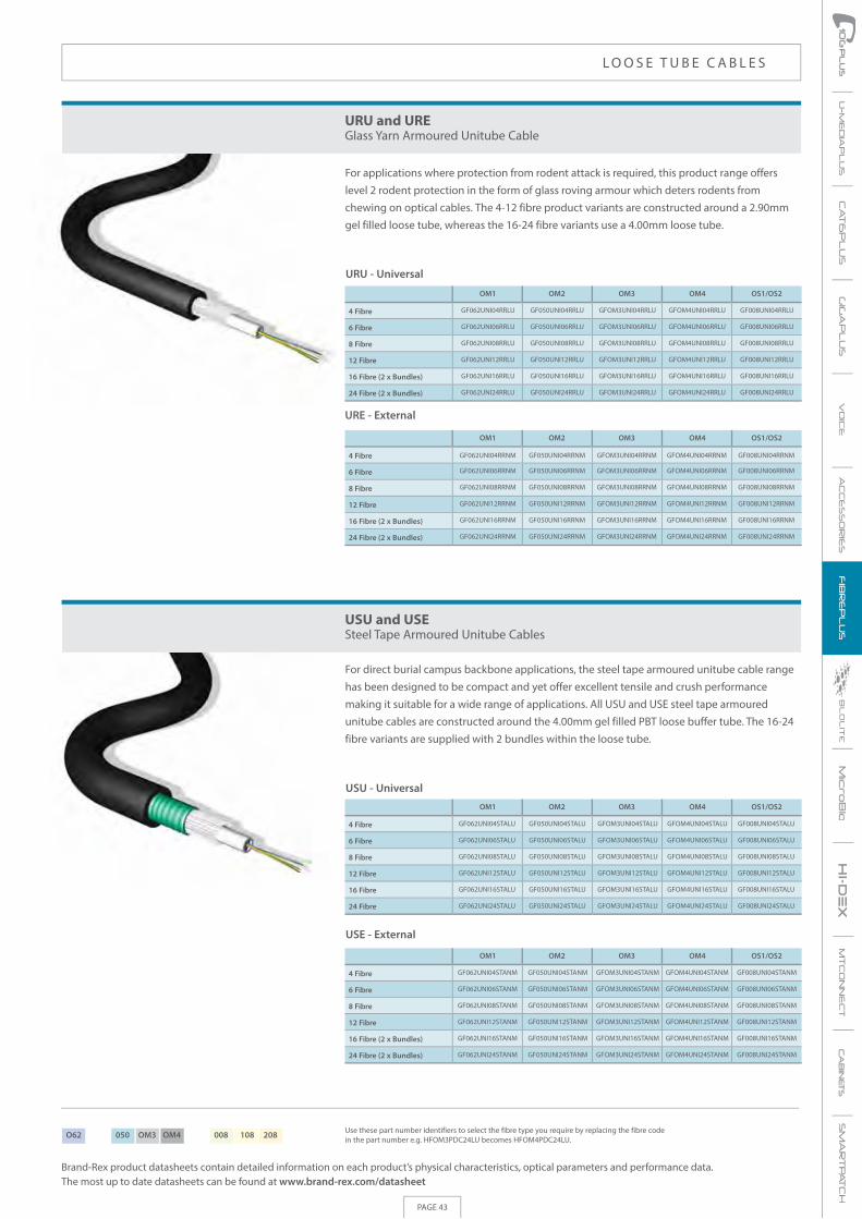
Brand-Rex product datasheets contain detailed information on each product’s physical characteristics, optical parameters and performance data. The most up to date datasheets can be found at www.brand-rex.com/datasheet
PAGE 43
AC
CE
SS
OR
IES
BC
AB
INET
S
For applications where protection from rodent attack is required, this product range offers level 2 rodent protection in the form of glass roving armour which deters rodents from chewing on optical cables. The 4-12 fibre product variants are constructed around a 2.90mm gel filled loose tube, whereas the 16-24 fibre variants use a 4.00mm loose tube.
For direct burial campus backbone applications, the steel tape armoured unitube cable range has been designed to be compact and yet offer excellent tensile and crush performance making it suitable for a wide range of applications. All USU and USE steel tape armoured unitube cables are constructed around the 4.00mm gel filled PBT loose buffer tube. The 16-24 fibre variants are supplied with 2 bundles within the loose tube.
URU and UREGlass Yarn Armoured Unitube Cable
USU and USESteel Tape Armoured Unitube Cables
4 Fibre
6 Fibre
8 Fibre
12 Fibre
16 Fibre (2 x Bundles)
24 Fibre (2 x Bundles)
4 Fibre
6 Fibre
8 Fibre
12 Fibre
16 Fibre
24 Fibre
4 Fibre
6 Fibre
8 Fibre
12 Fibre
16 Fibre (2 x Bundles)
24 Fibre (2 x Bundles)
4 Fibre
6 Fibre
8 Fibre
12 Fibre
16 Fibre (2 x Bundles)
24 Fibre (2 x Bundles)
OM1
OM1
OM1
OM1
OM2
OM2
OM2
OM2
OM3
OM3
OM3
OM3
OM4
OM4
OM4
OM4
OS1/OS2
OS1/OS2
OS1/OS2
OS1/OS2
URU - Universal
USU - Universal
USE - External
URE - External
GF062UNI24RRLU
GF062UNI16RRLU
GF062UNI12RRLU
GF062UNI08RRLU
GF062UNI06RRLU
GF062UNI04RRLU
GF050UNI24RRLU
GF050UNI16RRLU
GF050UNI12RRLU
GF050UNI08RRLU
GF050UNI06RRLU
GF050UNI04RRLU
GFOM3UNI24RRLU
GFOM3UNI16RRLU
GFOM3UNI12RRLU
GFOM3UNI08RRLU
GFOM3UNI06RRLU
GFOM3UNI04RRLU
GFOM4UNI24RRLU
GFOM4UNI16RRLU
GFOM4UNI12RRLU
GFOM4UNI08RRLU
GFOM4UNI06RRLU
GFOM4UNI04RRLU
GF008UNI24RRLU
GF008UNI16RRLU
GF008UNI12RRLU
GF008UNI08RRLU
GF008UNI06RRLU
GF008UNI04RRLU
GF062UNI24RRNM
GF062UNI16RRNM
GF062UNI12RRNM
GF062UNI08RRNM
GF062UNI06RRNM
GF062UNI04RRNM
GF050UNI24RRNM
GF050UNI16RRNM
GF050UNI12RRNM
GF050UNI08RRNM
GF050UNI06RRNM
GF050UNI04RRNM
GFOM3UNI24RRNM
GFOM3UNI16RRNM
GFOM3UNI12RRNM
GFOM3UNI08RRNM
GFOM3UNI06RRNM
GFOM3UNI04RRNM
GFOM4UNI24RRNM
GFOM4UNI16RRNM
GFOM4UNI12RRNM
GFOM4UNI08RRNM
GFOM4UNI06RRNM
GFOM4UNI04RRNM
GF008UNI24RRNM
GF008UNI16RRNM
GF008UNI12RRNM
GF008UNI08RRNM
GF008UNI06RRNM
GF008UNI04RRNM
GF062UNI24STALU
GF062UNI16STALU
GF062UNI12STALU
GF062UNI08STALU
GF062UNI06STALU
GF062UNI04STALU
GF050UNI24STALU
GF050UNI16STALU
GF050UNI12STALU
GF050UNI08STALU
GF050UNI06STALU
GF050UNI04STALU
GFOM3UNI24STALU
GFOM3UNI16STALU
GFOM3UNI12STALU
GFOM3UNI08STALU
GFOM3UNI06STALU
GFOM3UNI04STALU
GFOM4UNI24STALU
GFOM4UNI16STALU
GFOM4UNI12STALU
GFOM4UNI08STALU
GFOM4UNI06STALU
GFOM4UNI04STALU
GF008UNI24STALU
GF008UNI16STALU
GF008UNI12STALU
GF008UNI08STALU
GF008UNI06STALU
GF008UNI04STALU
GF062UNI24STANM
GF062UNI16STANM
GF062UNI12STANM
GF062UNI08STANM
GF062UNI06STANM
GF062UNI04STANM
GF050UNI24STANM
GF050UNI16STANM
GF050UNI12STANM
GF050UNI08STANM
GF050UNI06STANM
GF050UNI04STANM
GFOM3UNI24STANM
GFOM3UNI16STANM
GFOM3UNI12STANM
GFOM3UNI08STANM
GFOM3UNI06STANM
GFOM3UNI04STANM
GFOM4UNI24STANM
GFOM4UNI16STANM
GFOM4UNI12STANM
GFOM4UNI08STANM
GFOM4UNI06STANM
GFOM4UNI04STANM
GF008UNI24STANM
GF008UNI16STANM
GF008UNI12STANM
GF008UNI08STANM
GF008UNI06STANM
GF008UNI04STANM
L O O S E T U B E C A B L E S
Use these part number identifiers to select the fibre type you require by replacing the fibre code in the part number e.g. HFOM3PDC24LU becomes HFOM4PDC24LU.O62 050 OM3 OM4 008 108 208

PAGE 44
Brand-Rex product datasheets contain detailed information on each product’s physical characteristics, optical parameters and performance data. The most up to date datasheets can be found at www.brand-rex.com/datasheet
For direct burial campus backbone applications, the twin sheath universal steel tape armoured unitube cable range has been designed to be compact and yet offer excellent tensile and crush performance making it suitable for a wide range of applications. The 4-12 fibre product variants are constructed around a 2.90mm gel filled loose tube, whereas the 16-24 fibre variants use a 4.00mm loose tube.
For applications where a higher tensile load is required versus that offered by unitube constructions, the universal product range offers compact low fibre count duct grade cable. The product range consists of up to 6 x 2.1mm diameter loose tubes containing up to 4 fibres and solid fillers where required, stranded around a rigid glass non metallic central strength member. A layer of water blocking tape provides interstitial water blocking.
UTU and UTETwin Sheath Steel Tape Armoured Unitube Cables
Universal MDU 01 and External MDE 01Duct Grade Multi Loose Tube Cable
4 Fibre
6 Fibre
8 Fibre
12 Fibre
16 Fibre (2 x Bundles)
24 Fibre (2 x Bundles)
4 Fibre
8 Fibre
12 Fibre
16 Fibre
20 Fibre
24 Fibre
4 Fibre
8 Fibre
12 Fibre
16 Fibre
20 Fibre
24 Fibre
4 Fibre
6 Fibre
8 Fibre
12 Fibre
16 Fibre (2 x Bundles)
24 Fibre (2 x Bundles)
OM1
OM1
OM1
OM1
OM2
OM2
OM2
OM2
OM3
OM3
OM3
OM3
OM4
OM4
OM4
OM4
OS1/OS2
OS1/OS2
OS1/OS2
OS1/OS2
UTU - Universal
MDU 01 - Universal
MDE 01 - External
UTE - External
GF062UNI24LSTALU
GF062UNI16LSTALU
GF062UNI12LSTALU
GF062UNI08LSTALU
GF062UNI06LSTALU
GF062UNI04LSTALU
GF050UNI24LSTALU
GF050UNI16LSTALU
GF050UNI12LSTALU
GF050UNI08LSTALU
GF050UNI06LSTALU
GF050UNI04LSTALU
GFOM3UNI24LSTALU
GFOM3UNI16LSTALU
GFOM3UNI12LSTALU
GFOM3UNI08LSTALU
GFOM3UNI06LSTALU
GFOM3UNI04LSTALU
GFOM4UNI24LSTALU
GFOM4UNI16LSTALU
GFOM4UNI12LSTALU
GFOM4UNI08LSTALU
GFOM4UNI06LSTALU
GFOM4UNI04LSTALU
GF008UNI24LSTALU
GF008UNI16LSTALU
GF008UNI12LSTALU
GF008UNI08LSTALU
GF008UNI06LSTALU
GF008UNI04LSTALU
GF062UNI24NMSTANM
GF062UNI16NMSTANM
GF062UNI12NMSTANM
GF062UNI08NMSTANM
GF062UNI06NMSTANM
GF062UNI04NMSTANM
GF050UNI24NMSTANM
GF050UNI16NMSTANM
GF050UNI12NMSTANM
GF050UNI08NMSTANM
GF050UNI06NMSTANM
GF050UNI04NMSTANM
GFOM3UNI24NMSTANM
GFOM3UNI16NMSTANM
GFOM3UNI12NMSTANM
GFOM3UNI08NMSTANM
GFOM3UNI06NMSTANM
GFOM3UNI04NMSTANM
GFOM4UNI24NMSTANM
GFOM4UNI16NMSTANM
GFOM4UNI12NMSTANM
GFOM4UNI08NMSTANM
GFOM4UNI06NMSTANM
GFOM4UNI04NMSTANM
GF008UNI24NMSTANM
GF008UNI16NMSTANM
GF008UNI12NMSTANM
GF008UNI08NMSTANM
GF008UNI06NMSTANM
GF008UNI04NMSTANM
HF062S24WLU4FT
HF062S20WLU4FT
HF062S16WLU4FT
HF062S12WLU4FT
HF062S8WLU4FT
HF062S4WLU4FT
HF050S24WLU4FT
HF050S20WLU4FT
HF050S16WLU4FT
HF050S12WLU4FT
HF050S8WLU4FT
HF050S4WLU4FT
HFOM3S24WLU4FT
HFOM3S20WLU4FT
HFOM3S16WLU4FT
HFOM3S12WLU4FT
HFOM3S8WLU4FT
HFOM3S4WLU4FT
HFOM4S24WLU4FT
HFOM4S20WLU4FT
HFOM4S16WLU4FT
HFOM4S12WLU4FT
HFOM4S8WLU4FT
HFOM4S4WLU4FT
HF008S24WLU4FT
HF008S20WLU4FT
HF008S16WLU4FT
HF008S12WLU4FT
HF008S8WLU4FT
HF008S4WLU4FT
HF062S24WNM4FT
HF062S20WNM4FT
HF062S16WNM4FT
HF062S12WNM4FT
HF062S8WNM4FT
HF062S4WNM4FT
HF050S24WNM4FT
HF050S20WNM4FT
HF050S16WNM4FT
HF050S12WNM4FT
HF050S8WNM4FT
HF050S4WNM4FT
HFOM3S24WNM4FT
HFOM3S20WNM4FT
HFOM3S16WNM4FT
HFOM3S12WNM4FT
HFOM3S8WNM4FT
HFOM3S4WNM4FT
HFOM4S24WNM4FT
HFOM4S20WNM4FT
HFOM4S16WNM4FT
HFOM4S12WNM4FT
HFOM4S8WNM4FT
HFOM4S4WNM4FT
HF008S24WNM4FT
HF008S20WNM4FT
HF008S16WNM4FT
HF008S12WNM4FT
HF008S8WNM4FT
HF008S4WNM4FT
L O O S E T U B E C A B L E S
Use these part number identifiers to select the fibre type you require by replacing the fibre code in the part number e.g. HFOM3PDC24LU becomes HFOM4PDC24LU.O62 050 OM3 OM4 008 108 208

Brand-Rex product datasheets contain detailed information on each product’s physical characteristics, optical parameters and performance data. The most up to date datasheets can be found at www.brand-rex.com/datasheet
PAGE 45
AC
CE
SS
OR
IES
BC
AB
INET
S
For building and campus backbone applications where higher fibre counts are required, the product range offers a compact duct grade cable. The product range consists of up to 5 x 2.5mm diameter loose tubes containing up to 12 fibres and solid fillers where required, stranded around a rigid glass non metallic central strength member. A layer of water blocking tape provides interstitial water blocking.
For building and campus backbone applications where higher fibre counts are required, the product range offers a compact duct grade cable. The product range consists of up to 6 x 2.5mm diameter loose tubes containing up to 12 fibres and solid fillers where required, stranded around a rigid glass non metallic central strength member. A layer of water blocking tape provides interstitial water blocking.
Universal MDU 06 and External MDE 06Duct Grade Multi Loose Tube Cable
Universal MDU 02 and External MDE 02Duct Grade Multi Loose Tube Cable
12 Fibre
24 Fibre
36 Fibre
48 Fibre
60 Fibre
72 Fibre
72 Fibre
12 Fibre
24 Fibre
36 Fibre
48 Fibre
60 Fibre
OM1
OM1
OM1
OM1
OM2
OM2
OM2
OM2
OM3
OM3
OM3
OM3
OM4
OM4
OM4
OM4
OS1/OS2
OS1/OS2
OS1/OS2
OS1/OS2
MDU 06 - Universal
MDU 02 - Universal
MDE 06 - External
MDE 02 - External
GF062S60WLU
GF062S48WLU
GF062S36WLU
GF062S24WLU
GF062S12WLU
GF050S60WLU
GF050S48WLU
GF050S36WLU
GF050S24WLU
GF050S12WLU
GFOM3S60WLU
GFOM3S48WLU
GFOM3S36WLU
GFOM3S24WLU
GFOM3S12WLU
GFOM4S60WLU
GFOM4S48WLU
GFOM4S36WLU
GFOM4S24WLU
GFOM4S12WLU
GF008S60WLU
GF008S48WLU
GF008S36WLU
GF008S24WLU
GF008S12WLU
GF062S60WNM
GF062S48WNM
GF062S36WNM
GF062S24WNM
GF062S12WNM
GF050S60WNM
GF050S48WNM
GF050S36WNM
GF050S24WNM
GF050S12WNM
GFOM3S60WNM
GFOM3S48WNM
GFOM3S36WNM
GFOM3S24WNM
GFOM3S12WNM
GFOM4S60WNM
GFOM4S48WNM
GFOM4S36WNM
GFOM4S24WNM
GFOM4S12WNM
GF008S60WNM
GF008S48WNM
GF008S36WNM
GF008S24WNM
GF008S12WNM
HF062S72WLU HF050S72WLU HFOM3S72WLU HFOM4S72WLU HF008S72WLU
HF062S72WNM HF050S72WNM HFOM3S72WNM HFOM4S72WNM HF008S72WNM
L O O S E T U B E C A B L E S
Use these part number identifiers to select the fibre type you require by replacing the fibre code in the part number e.g. HFOM3PDC24LU becomes HFOM4PDC24LU.O62 050 OM3 OM4 008 108 208

PAGE 46
Brand-Rex product datasheets contain detailed information on each product’s physical characteristics, optical parameters and performance data. The most up to date datasheets can be found at www.brand-rex.com/datasheet
For building and campus backbone applications where higher fibre counts are required, the product range offers a compact duct grade cable. The product range consists of up to 8 x 2.5mm diameter loose tubes containing up to 12 fibres and solid fillers where required, stranded around a rigid glass non metallic central strength member. A layer of water blocking tape provides interstitial water blocking.
For higher fibre count building and campus backbone applications the product range delivers up to 144 fibres in a compact duct grade construction. The product range consists of up to 12 x 2.50mm loose tubes containing up to 12 fibres and solid fillers where required, stranded around a sheathed rigid glass non metallic central strength member. A layer of water blocking tape provides interstitial water blocking.
Universal MDU 04 and External MDE 04Duct Grade Multi Loose Tube Cable
Universal MDU 03 and External MDE 03Duct Grade Multi Loose Tube Cable
84 Fibre
96 Fibre
108 Fibre
120 Fibre
132 Fibre
144 Fibre
108 Fibre
120 Fibre
132 Fibre
144 Fibre
84 Fibre
96 Fibre
OM1
OM1
OM1
OM1
OM2
OM2
OM2
OM2
OM3
OM3
OM3
OM3
OM4
OM4
OM4
OM4
OS1/OS2
OS1/OS2
OS1/OS2
OS1/OS2
MDU 04 - Universal
MDU 03 - Universal
MDE 03 - External
MDE 04 - External
HF062S84WLU
HF062S96WLU
HF050S84WLU
HF050S96WLU
HFOM3S84WLU
HFOM3S96WLU
HFOM4S84WLU
HFOM4S96WLU
HF008S84WLU
HF008S96WLU
HF062S84WNM
HF062S96WNM
HF050S84WNM
HF050S96WNM
HFOM3S84WNM
HFOM3S96WNM
HFOM4S84WNM
HFOM4S96WNM
HF008S84WNM
HF008S96WNM
HF062S144WLU
HF062S132WLU
HF062S120WLU
HF062S108WLU
HF050S144WLU
HF050S132WLU
HF050S120WLU
HF050S108WLU
HFOM3S144WLU
HFOM3S132WLU
HFOM3S120WLU
HFOM3108WLU
HFOM4S144WLU
HFOM4S132WLU
HFOM4S120WLU
HFOM4108WLU
HF008S144WLU
HF008S132WLU
HF008S120WLU
HF008S108WLU
HF062S144WNM
HF062S132WNM
HF062S120WNM
HF062S108WNM
HF050S144WNM
HF050S132WNM
HF050S120WNM
HF050S108WNM
HFOM3S144WNM
HFOM3S132WNM
HFOM3S120WNM
HFOM3108WNM
HFOM4S144WNM
HFOM4S132WNM
HFOM4S120WNM
HFOM4108WNM
HF008S144WNM
HF008S132WNM
HF008S120WNM
HF008S108WNM
L O O S E T U B E C A B L E S
Use these part number identifiers to select the fibre type you require by replacing the fibre code in the part number e.g. HFOM3PDC24LU becomes HFOM4PDC24LU.O62 050 OM3 OM4 008 108 208

Brand-Rex product datasheets contain detailed information on each product’s physical characteristics, optical parameters and performance data. The most up to date datasheets can be found at www.brand-rex.com/datasheet
PAGE 47
AC
CE
SS
OR
IES
BC
AB
INET
S
For higher fibre count building and campus backbone applications the product range delivers up to 216 fibres in a compact duct grade construction. The product range consists of up to 18 x 2.50mm loose tubes containing up to 12 fibres and solid fillers where required, stranded around a sheathed rigid glass non metallic central strength member. A layer of water blocking tape provides interstitial water blocking.
For applications where protection from rodent attack is required and a higher tensile load is required, the universal MRR product range offers rodent protection in the form of glass roving armour which deters rodents from chewing on optical cables. The product range consists up to 6 x 2.10mm loose tubes containing up to 4 fibres and solid fillers where required, stranded around a rigid glass non metallic central strength member. A layer of water blocking tape provides interstitial water blocking.
Universal MDU 05 and External MDE 05Duct Grade Multi Loose Tube Cable
Universal MRU 01 and External MRE 01Glass Yarn Armoured Rodent Resistant Multi Loose Tube Cable
156 Fibre
168 Fibre
180 Fibre
192 Fibre
204 Fibre
216 Fibre
156 Fibre
168 Fibre
180 Fibre
192 Fibre
204 Fibre
216 Fibre
OM1
OM1
OM1
OM1
OM2
OM2
OM2
OM2
OM3
OM3
OM3
OM3
OM4
OM4
OM4
OM4
OS1/OS2
OS1/OS2
OS1/OS2
OS1/OS2
MDU 05 - Universal
MRU 01 - Universal
MDE 05 - Universal
MRE 01 - External
HF062S192WLU
HF062S180WLU
HF062S168WLU
HF062S156WLU
HF062S204WLU
HF062S216WLU
HF050S192WLU
HF050S180WLU
HF050S168WLU
HF050S156WLU
HF050S204WLU
HF050S216WLU
HFOM3S192WLU
HFOM3S180WLU
HFOM3S168WLU
HFOM3S156WLU
HFOM3S204WLU
HFOM3S216WLU
HFOM4S192WLU
HFOM4S180WLU
HFOM4S168WLU
HFOM4S156WLU
HFOM4S204WLU
HFOM4S216WLU
HF008S192WLU
HF008S180WLU
HF008S168WLU
HF008S156WLU
HF008S204WLU
HF008S216WLU
HF062S192WNM
HF062S180WNM
HF062S168WNM
HF062S156WNM
HF062S204WNM
HF062S216WNM
HF050S192WNM
HF050S180WNM
HF050S168WNM
HF050S156WNM
HF050S204WNM
HF050S216WNM
HFOM3S192WNM
HFOM3S180WNM
HFOM3S168WNM
HFOM3156WNM
HFOM3S204WNM
HFOM3S216WNM
HFOM4S192WNM
HFOM4S180WNM
HFOM4S168WNM
HFOM4156WNM
HFOM4S204WNM
HFOM4S216WNM
HF008S192WNM
HF008S180WNM
HF008S168WNM
HF008S156WNM
HF008S204WNM
HF008S216WNM
HF062S24WRRLU4FT
HF062S20WRRLU4FT
HF062S16WRRLU4FT
HF062S12WRRLU4FT
HF062S8WRRLU4FT
HF062S4WRRLU4FT
HF050S24WRRLU4FT
HF050S20WRRLU4FT
HF050S16WRRLU4FT
HF050S12WRRLU4FT
HF050S8WRRLU4FT
HF050S4WRRLU4FT
HFOM3S24WRRLU4FT
HFOM3S20WRRLU4FT
HFOM3S16WRRLU4FT
HFOM3S12WRRLU4FT
HFOM3S8WRRLU4FT
HFOM3S4WRRLU4FT
HFOM4S24WRRLU4FT
HFOM4S20WRRLU4FT
HFOM4S16WRRLU4FT
HFOM4S12WRRLU4FT
HFOM4S8WRRLU4FT
HFOM4S4WRRLU4FT
HF008S24WRRLU4FT
HF008S20WRRLU4FT
HF008S16WRRLU4FT
HF008S12WRRLU4FT
HF008S8WRRLU4FT
HF008S4WRRLU4FT
HF062S24WRRNM4FT
HF062S20WRRNM4FT
HF062S16WRRNM4FT
HF062S12WRRNM4FT
HF062S8WRRNM4FT
HF062S4WRRNM4FT
HF050S24WRRNM4FT
HF050S20WRRNM4FT
HF050S16WRRNM4FT
HF050S12WRRNM4FT
HF050S8WRRNM4FT
HF050S4WRRNM4FT
HFOM3S24WRRNM4FT
HFOM3S20WRRNM4FT
HFOM3S16WRRNM4FT
HFOM3S12WRRNM4FT
HFOM3S8WRRNM4FT
HFOM3S4WRRNM4FT
HFOM4S24WRRNM4FT
HFOM4S20WRRNM4FT
HFOM4S16WRRNM4FT
HFOM4S12WRRNM4FT
HFOM4S8WRRNM4FT
HFOM4S4WRRNM4FT
HF008S24WRRNM4FT
HF008S20WRRNM4FT
HF008S16WRRNM4FT
HF008S12WRRNM4FT
HF008S8WRRNM4FT
HF008S4WRRNM4FT
4 Fibre
6 Fibre
8 Fibre
12 Fibre
16 Fibre
24 Fibre
4 Fibre
6 Fibre
8 Fibre
12 Fibre
16 Fibre
24 Fibre
L O O S E T U B E C A B L E S
Use these part number identifiers to select the fibre type you require by replacing the fibre code in the part number e.g. HFOM3PDC24LU becomes HFOM4PDC24LU.O62 050 OM3 OM4 008 108 208

PAGE 48
Brand-Rex product datasheets contain detailed information on each product’s physical characteristics, optical parameters and performance data. The most up to date datasheets can be found at www.brand-rex.com/datasheet
For applications where protection from rodent attack and higher fibre counts are required, the universal product range offers rodent protection in the form of glass roving armour which deters rodents from chewing on optical cables. The product range consists up to 6 x 2.50mm loose tubes containing up to 12 fibres and solid fillers where required, stranded around a rigid glass non metallic central strength member. A layer of water blocking tape provides interstitial water blocking.
For applications where protection from rodent attack and higher fibre counts are required, the universal product range offers rodent protection in the form of glass roving armour which deters rodents from chewing on optical cables. The product range consists of up to 8 x 2.50mm loose tubes containing up to 12 fibres and solid fillers where required, stranded around a rigid glass non metallic central strength member. A layer of water blocking tape provides interstitial water blocking.
Universal MRU 02 and External MRE 02Glass Yarn Armoured Rodent Resistant Multi Loose Tube Cable
Universal MRU 04 and External MRE 04Glass Yarn Armoured Rodent Resistant Multi Loose Tube Cable
OM1
OM1
OM1
OM1
OM2
OM2
OM2
OM2
OM3
OM3
OM3
OM3
OM4
OM4
OM4
OM4
OS1/OS2
OS1/OS2
OS1/OS2
OS1/OS2
MRU 02 - Universal
MRU 04 - Universal
MRU 04 - Universal
MRE 02 - External
12 Fibre
24 Fibre
36 Fibre
48 Fibre
60 Fibre
72 Fibre
84 Fibre
96 Fibre
84 Fibre
96 Fibre
12 Fibre
24 Fibre
36 Fibre
48 Fibre
60 Fibre
72 Fibre
HF062S72WRRLU
HF062S60WRRLU
HF062S48WRRLU
HF062S36WRRLU
HF062S24WRRLU
HF062S12WRRLU
HF050S72WRRLU
HF050S60WRRLU
HF050S48WRRLU
HF050S36WRRLU
HF050S24WRRLU
HF050S12WRRLU
HFOM3S72WRRLU
HFOM3S60WRRLU
HFOM3S48WRRLU
HFOM3S36WRRLU
HFOM3S24WRRLU
HFOM3S12WRRLU
HFOM4S72WRRLU
HFOM4S60WRRLU
HFOM4S48WRRLU
HFOM4S36WRRLU
HFOM4S24WRRLU
HFOM4S12WRRLU
HF008S72WRRLU
HF008S60WRRLU
HF008S48WRRLU
HF008S36WRRLU
HF008S24WRRLU
HF008S12WRRLU
HF062S72WRRNM
HF062S60WRRNM
HF062S48WRRNM
HF062S36WRRNM
HF062S24WRRNM
HF062S12WRRNM
HF050S72WRRNM
HF050S60WRRNM
HF050S48WRRNM
HF050S36WRRNM
HF050S24WRRNM
HF050S12WRRNM
HFOM3S72WRRNM
HFOM3S60WRRNM
HFOM3S48WRRNM
HFOM3S36WRRNM
HFOM3S24WRRNM
HFOM3S12WRRNM
HFOM4S72WRRNM
HFOM4S60WRRNM
HFOM4S48WRRNM
HFOM4S36WRRNM
HFOM4S24WRRNM
HFOM4S12WRRNM
HF008S72WRRNM
HF008S60WRRNM
HF008S48WRRNM
HF008S36WRRNM
HF008S24WRRNM
HF008S12WRRNM
HF062S84WRRLU
HF062S96WRRLU
HF050S84WRRLU
HF050S96WRRLU
HFOM3S84WRRLU
HFOM3S96WRRLU
HFOM4S84WRRLU
HFOM4S96WRRLU
HF008S84WRRLU
HF008S96WRRLU
HF062S84WRRNM
HF062S96WRRNM
HF050S84WRRNM
HF050S96WRRNM
HFOM3S84WRRNM
HFOM3S96WRRNM
HFOM4S84WRRNM
HFOM4S96WRRNM
HF008S84WRRNM
HF008S96WRRNM
L O O S E T U B E C A B L E S
Use these part number identifiers to select the fibre type you require by replacing the fibre code in the part number e.g. HFOM3PDC24LU becomes HFOM4PDC24LU.O62 050 OM3 OM4 008 108 208

Brand-Rex product datasheets contain detailed information on each product’s physical characteristics, optical parameters and performance data. The most up to date datasheets can be found at www.brand-rex.com/datasheet
PAGE 49
AC
CE
SS
OR
IES
BC
AB
INET
S
For applications where protection from rodent attack and higher fibre counts are required, the universal product range offers rodent protection in the form of glass roving armour that deters rodents from chewing on optical cables. The product range consists of up to 12 x 2.50mm loose tubes containing up to 12 fibres and solid fillers where required, stranded around a sheathed rigid glass non metallic central strength member. A layer of water blocking tape provides interstitial water blocking.
For applications where protection from rodent attack and higher fibre counts are required, the universal product range offers rodent protection in the form of glass roving armour that deters rodents from chewing on optical cables. The product range consists of up to 18 x 2.50mm loose tubes containing up to 12 fibres and solid fillers where required, stranded around a sheathed rigid glass non metallic central strength member. A layer of water blocking tape provides interstitial water blocking.
Universal MRU 03 and External MRE 03Glass Yarn Armoured Rodent Resistant Multi Loose Tube Cable
Universal MRU 05 and External MRE 05Glass Yarn Armoured Rodent Resistant Multi Loose Tube Cable
OM1
OM1
OM2
OM2
OM3
OM3
OM4
OM4
OS1/OS2
OS1/OS2
MRU 03 - Universal
MRE 03 - External
108 Fibre
120 Fibre
132 Fibre
144 Fibre
108 Fibre
120 Fibre
132 Fibre
144 Fibre
HF062S144WRRLU
HF062S132WRRLU
HF062S120WRRLU
HF062S108WRRLU
HF050S144WRRLU
HF050S132WRRLU
HF050S120WRRLU
HF050S108WRRLU
HFOM3S144WRRLU
HFOM3S132WRRLU
HFOM3S120WRRLU
HFOM3S108WRRLU
HFOM4S144WRRLU
HFOM4S132WRRLU
HFOM4S120WRRLU
HFOM4S108WRRLU
HF008S144WRRLU
HF008S132WRRLU
HF008S120WRRLU
HF008S108WRRLU
HF062S144WRRNM
HF062S132WRRNM
HF062S120WRRNM
HF062S108WRRNM
HF050S144WRRNM
HF050S132WRRNM
HF050S120WRRNM
HF050S108WRRNM
HFOM3S144WRRNM
HFOM3S132WRRNM
HFOM3S120WRRNM
HFOM3S108WRRNM
HFOM4S144WRRNM
HFOM4S132WRRNM
HFOM4S120WRRNM
HFOM4S108WRRNM
HF008S144WRRNM
HF008S132WRRNM
HF008S120WRRNM
HF008S108WRRNM
OM1
OM1
OM2
OM2
OM3
OM3
OM4
OM4
OS1/OS2
OS1/OS2
MRU 05 - Universal
MRE 05 - External
156 Fibre
168 Fibre
180 Fibre
192 Fibre
204 Fibre
216 Fibre
156 Fibre
168 Fibre
180 Fibre
192 Fibre
204 Fibre
216 Fibre
HF062S192WRRLU
HF062S180WRRLU
HF062S168WRRLU
HF062S156WRRLU
HF062S204WRRLU
HF062S216WRRLU
HF050S192WRRLU
HF050S180WRRLU
HF050S168WRRLU
HF050S156WRRLU
HF050S204WRRLU
HF050S216WRRLU
HFOM3S192WRRLU
HFOM3S180WRRLU
HFOM3S168WRRLU
HFOM3S156WRRLU
HFOM3S204WRRLU
HFOM3S216WRRLU
HFOM4S192WRRLU
HFOM4S180WRRLU
HFOM4S168WRRLU
HFOM4S156WRRLU
HFOM4S204WRRLU
HFOM4S216WRRLU
HF008S192WRRLU
HF008S180WRRLU
HF008S168WRRLU
HF008S156WRRLU
HF008S204WRRLU
HF008S216WRRLU
HF062S192WRRNM
HF062S180WRRNM
HF062S168WRRNM
HF062S156WRRNM
HF062S204WRRNM
HF062S216WRRNM
HF050S192WRRNM
HF050S180WRRNM
HF050S168WRRNM
HF050S156WRRNM
HF050S204WRRNM
HF050S216WRRNM
HFOM3S192WRRNM
HFOM3S180WRRNM
HFOM3S168WRRNM
HFOM3S156WRRNM
HFOM3S204WRRNM
HFOM3S216WRRNM
HFOM4S192WRRNM
HFOM4S180WRRNM
HFOM4S168WRRNM
HFOM4S156WRRNM
HFOM4S204WRRNM
HFOM4S216WRRNM
HF008S192WRRNM
HF008S180WRRNM
HF008S168WRRNM
HF008S156WRRNM
HF008S204WRRNM
HF008S216WRRNM
L O O S E T U B E C A B L E S
Use these part number identifiers to select the fibre type you require by replacing the fibre code in the part number e.g. HFOM3PDC24LU becomes HFOM4PDC24LU.O62 050 OM3 OM4 008 108 208

PAGE 50
Brand-Rex product datasheets contain detailed information on each product’s physical characteristics, optical parameters and performance data. The most up to date datasheets can be found at www.brand-rex.com/datasheet
For applications where a higher tensile load is required versus that offered by unitube constructions, this product range offers a compact low fibre count direct burial grade cable. The product range consists of up to 6 x 2.10mm loose tubes containing up to 4 fibres and solid fillers where required, stranded around a rigid glass non metallic central strength member.A layer of water blocking tape provides interstitial water blocking and a layer of corrugated steel tape armour provides additional crush resistance.
For direct burial applications, the single sheathed product range offers up to 72 fibres in a compact and relatively flexible construction. The product range consists of up to 6 x 2.50mm loose tubes containing up to 12 fibres and solid fillers where required, stranded around a rigid glass non metallic central strength member. A layer of water blocking tape provides interstitial water blocking and a layer of steel tape armour provides additional crush resistance.
Universal MSU 01 and External MSE 01Direct Burial Steel Tape Armoured Multi Loose Tube Cable
Universal MSU 02 and External MSE 02Direct Burial Steel Tape Armoured Multi Loose Tube Cable
OM1
OM1
OM1
OM1
OM2
OM2
OM2
OM2
OM3
OM3
OM3
OM3
OM4
OM4
OM4
OM4
OS1/OS2
OS1/OS2
OS1/OS2
OS1/OS2
MSU 01 - Universal
MSU 02 - Universal
MSE 01 - External
MSE 02 - External
4 Fibre
6 Fibre
8 Fibre
12 Fibre
16 Fibre
24 Fibre
12 Fibre
24 Fibre
36 Fibre
48 Fibre
60 Fibre
72 Fibre
12 Fibre
24 Fibre
36 Fibre
48 Fibre
60 Fibre
72 Fibre
4 Fibre
6 Fibre
8 Fibre
12 Fibre
16 Fibre
24 Fibre
HF062S24WSTALU4FT
HF062S20WSTALU4FT
HF062S16WSTALU4FT
HF062S12WSTALU4FT
HF062S8WSTALU4FT
HF062S4WSTALU4FT
HF050S24WSTALU4FT
HF050S20WSTALU4FT
HF050S16WSTALU4FT
HF050S12WSTALU4FT
HF050S8WSTALU4FT
HF050S4WSTALU4FT
HFOM3S24WSTALU4FT
HFOM3S20WSTALU4FT
HFOM3S16WSTALU4FT
HFOM3S12WSTALU4FT
HFOM3S8WSTALU4FT
HFOM3S4WSTALU4FT
HFOM4S24WSTALU4FT
HFOM4S20WSTALU4FT
HFOM4S16WSTALU4FT
HFOM4S12WSTALU4FT
HFOM4S8WSTALU4FT
HFOM4S4WSTALU4FT
HF008S24WSTALU4FT
HF008S20WSTALU4FT
HF008S16WSTALU4FT
HF008S12WSTALU4FT
HF008S8WSTALU4FT
HF008S4WSTALU4FT
HF062S24WSTANM4FT
HF062S20WSTANM4FT
HF062S16WSTANM4FT
HF062S12WSTANM4FT
HF062S8WSTANM4FT
HF062S4WSTANM4FT
HF050S24WSTANM4FT
HF050S20WSTANM4FT
HF050S16WSTANM4FT
HF050S12WSTANM4FT
HF050S8WSTANM4FT
HF050S4WSTANM4FT
HFOM3S24WSTANM4FT
HFOM3S20WSTANM4FT
HFOM3S16WSTANM4FT
HFOM3S12WSTANM4FT
HFOM3S8WSTANM4FT
HFOM3S4WSTANM4FT
HFOM4S24WSTANM4FT
HFOM4S20WSTANM4FT
HFOM4S16WSTANM4FT
HFOM4S12WSTANM4FT
HFOM4S8WSTANM4FT
HFOM4S4WSTANM4FT
HF008S24WSTANM4FT
HF008S20WSTANM4FT
HF008S16WSTANM4FT
HF008S12WSTANM4FT
HF008S8WSTANM4FT
HF008S4WSTANM4FT
HF062S72WSTALU
HF062S60WSTALU
HF062S48WSTALU
HF062S36WSTALU
HF062S24WSTALU
HF062S12WSTALU
HF050S72WSTALU
HF050S60WSTALU
HF050S48WSTALU
HF050S36WSTALU
HF050S24WSTALU
HF050S12WSTALU
HFOM3S72WSTALU
HFOM3S60WSTALU
HFOM3S48WSTALU
HFOM3S36WSTALU
HFOM3S24WSTALU
HFOM3S12WSTALU
HFOM4S72WSTALU
HFOM4S60WSTALU
HFOM4S48WSTALU
HFOM4S36WSTALU
HFOM4S24WSTALU
HFOM4S12WSTALU
HF008S72WSTALU
HF008S60WSTALU
HF008S48WSTALU
HF008S36WSTALU
HF008S24WSTALU
HF008S12WSTALU
HF062S72WSTANM
HF062S60WSTANM
HF062S48WSTANM
HF062S36WSTANM
HF062S24WSTANM
HF062S12WSTANM
HF050S72WSTANM
HF050S60WSTANM
HF050S48WSTANM
HF050S36WSTANM
HF050S24WSTANM
HF050S12WSTANM
HFOM3S72WSTANM
HFOM3S60WSTANM
HFOM3S48WSTANM
HFOM3S36WSTANM
HFOM3S24WSTANM
HFOM3S12WSTANM
HFOM4S72WSTANM
HFOM4S60WSTANM
HFOM4S48WSTANM
HFOM4S36WSTANM
HFOM4S24WSTANM
HFOM4S12WSTANM
HF008S72WSTANM
HF008S60WSTANM
HF008S48WSTANM
HF008S36WSTANM
HF008S24WSTANM
HF008S12WSTANM
L O O S E T U B E C A B L E S
Use these part number identifiers to select the fibre type you require by replacing the fibre code in the part number e.g. HFOM3PDC24LU becomes HFOM4PDC24LU.O62 050 OM3 OM4 008 108 208

Brand-Rex product datasheets contain detailed information on each product’s physical characteristics, optical parameters and performance data. The most up to date datasheets can be found at www.brand-rex.com/datasheet
PAGE 51
AC
CE
SS
OR
IES
BC
AB
INET
S
For direct burial applications, the single sheathed product range offers up to 144 fibres in a compact and relatively flexible construction. The product range consists of up to 12 x 2.50mm loose tubes containing up to 12 fibres and solid fillers where required, stranded around a sheathed rigid glass non metallic central strength member. A layer of water blocking tape provides interstitial water blocking and a layer of corrugated steel tape armour gives additional crush resistance.
For direct burial applications, the single sheathed product range offers up to 96 fibres in a compact and relatively flexible construction. The product range consists of up to 8 x 2.50mm loose tubes containing up to 12 fibres and solid fillers where required, stranded around a rigid glass non metallic central strength member. A layer of water blocking tape provides interstitial water blocking and a layer of steel tape armour provides additional crush resistance.
Universal MSU 04 and External MSE 04Direct Burial Steel Tape Armoured Multi Loose Tube Cable
Universal MSU 03 and External MSE 03Direct Burial Steel Tape Armoured Multi Loose Tube cable
OM1
OM1
OM1
OM1
OM2
OM2
OM2
OM2
OM3
OM3
OM3
OM3
OM4
OM4
OM4
OM4
OS1/OS2
OS1/OS2
OS1/OS2
OS1/OS2
MSU 04 - Universal
MSU 03 - Universal
MSE 04 - External
MSE 03 - External
84 Fibre
96 Fibre
84 Fibre
96 Fibre
108 Fibre
120 Fibre
132 Fibre
144 Fibre
108 Fibre
120 Fibre
132 Fibre
144 Fibre
HF062S84WSTALU
HF062S96WSTALU
HF050S84WSTALU
HF050S96WSTALU
HFOM3S84WSTALU
HFOM3S96WSTALU
HFOM4S84WSTALU
HFOM4S96WSTALU
HF008S84WSTALU
HF008S96WSTALU
HF062S96WSTANM
HF062S84WSTANM
HF050S96WSTANM
HF050S84WSTANM
HFOM3S96WSTANM
HFOM3S84WSTANM
HFOM4S96WSTANM
HFOM4S84WSTANM
HF008S96WSTANM
HF008S84WSTANM
HF062S144WSTALU
HF062S132WSTALU
HF062S120WSTALU
HF062S108WSTALU
HF050S144WSTALU
HF050S132WSTALU
HF050S120WSTALU
HF050S108WSTALU
HFOM3S144WSTALU
HFOM3S132WSTALU
HFOM3S120WSTALU
HFOM3S108WSTALU
HFOM4S144WSTALU
HFOM4S132WSTALU
HFOM4S120WSTALU
HFOM4S108WSTALU
HF008144WSTALU
HF008S132WSTALU
HF008S120WSTALU
HF008S108WSTALU
HF062S144WSTANM
HF062S132WSTANM
HF062S120WSTANM
HF062S108WSTANM
HF050S144WSTANM
HF050S132WSTANM
HF050S120WSTANM
HF050S108WSTANM
HFOM3S144WSTANM
HFOM3S132WSTANM
HFOM3S120WSTANM
HFOM3S108WSTANM
HFOM4S144WSTANM
HFOM4S132WSTANM
HFOM4S120WSTANM
HFOM4S108WSTANM
HF008144WSTANM
HF008S132WSTANM
HF008S120WSTANM
HF008S108WSTANM
L O O S E T U B E C A B L E S
Use these part number identifiers to select the fibre type you require by replacing the fibre code in the part number e.g. HFOM3PDC24LU becomes HFOM4PDC24LU.O62 050 OM3 OM4 008 108 208

PAGE 52
Brand-Rex product datasheets contain detailed information on each product’s physical characteristics, optical parameters and performance data. The most up to date datasheets can be found at www.brand-rex.com/datasheet
For direct burial applications, the single sheathed product range offers up to 216 fibres in a compact and relatively flexible construction. The product range consists of up to18 x 2.50mm loose tubes containing up to 12 fibres and solid fillers where required, stranded around a sheathed rigid glass non metallic central strength member. A layer of water blocking tape provides interstitial water blocking and a layer of corrugated steel tape armour gives additional crush resistance.
For applications where a higher tensile load is required versus that offered by unitube constructions, the universal product range offers a compact low fibre count direct burial grade cable. The product range consists of up to 6 x 2.10mm loose tubes containing up to 4 fibres and solid fillers where required, stranded around a rigid glass non metallic central strength member. A layer of water blocking tape provides interstitial water blocking and the LSHF or PE inner sheath and a layer of corrugated steel tape armour provide additional crush resistance.
Universal MSU 05 and External MSE 05Direct Burial Steel Tape Armoured Multi Loose Tube cable
Universal MTU 01 and External MTE 01Twin Sheath Steel Tape Armoured Multi Loose Tube Cable
For direct burial applications, the single sheathed product range offers up to 216 fibres in a compact and relatively flexible construction. The product range consists of up to18 x 2.50mm loose tubes containing up to 12 fibres and solid fillers where required, stranded around a sheathed rigid glass non metallic central strength member. A layer of water blocking tape provides interstitial water blocking and a layer of corrugated steel tape armour gives additional crush resistance.
OM1
OM1
OM2
OM2
OM3
OM3
OM4
OM4
OS1/OS2
OS1/OS2
MSU 05 - Universal
MSE 05 - External
156 Fibre
168 Fibre
180 Fibre
192 Fibre
204 Fibre
216 Fibre
156 Fibre
168 Fibre
180 Fibre
192 Fibre
204 Fibre
216 Fibre
HF062S192WSTALU
HF062S180WSTALU
HF062S168WSTALU
HF062S156WSTALU
HF062S216WSTALU
HF062S204WSTALU
HF050S192WSTALU
HF050S180WSTALU
HF050S168WSTALU
HF050S156WSTALU
HF050S216WSTALU
HF050S204WSTALU
HFOM3S192WSTALU
HFOM3S180WSTALU
HFOM3S168WSTALU
HFOM3S156WSTALU
HFOM3S216WSTALU
HFOM3S204WSTALU
HFOM4S192WSTALU
HFOM4S180WSTALU
HFOM4S168WSTALU
HFOM4S156WSTALU
HFOM4S216WSTALU
HFOM4S204WSTALU
HF008S192WSTALU
HF008S180WSTALU
HF008S168WSTALU
HF008S156WSTALU
HF008S216WSTALU
HF008S204WSTALU
HF062S192WSTANM
HF062S180WSTANM
HF062S168WSTANM
HF062S156WSTANM
HF062S216WSTANM
HF062S204WSTANM
HF050S192WSTANM
HF050S180WSTANM
HF050S168WSTANM
HF050S156WSTANM
HF050S216WSTANM
HF050S204WSTANM
HFOM3S192WSTANM
HFOM3S180WSTANM
HFOM3S168WSTANM
HFOM3S156WSTANM
HFOM3S216WSTANM
HFOM3S204WSTANM
HFOM4S192WSTANM
HFOM4S180WSTANM
HFOM4S168WSTANM
HFOM4S156WSTANM
HFOM4S216WSTANM
HFOM4S204WSTANM
HF008S192WSTANM
HF008S180WSTANM
HF008S168WSTANM
HF008S156WSTANM
HF008S216WSTANM
HF008S204WSTANM
OM1
OM1
OM2
OM2
OM3
OM3
OM4
OM4
OS1/OS2
OS1/OS2
MTU 01 - Universal
MTE 01 - External
4 Fibre
8 Fibre
12 Fibre
16 Fibre
20 Fibre
24 Fibre
4 Fibre
8 Fibre
12 Fibre
16 Fibre
20 Fibre
24 Fibre
HF062S24WLSTALU4FT
HF062S20WLSTALU4FT
HF062S16WLSTALU4FT
HF062S12WLSTALU4FT
HF062S8WLSTALU4FT
HF062S4WLSTALU4FT
HF050S24WLSTALU4FT
HF050S20WLSTALU4FT
HF050S16WLSTALU4FT
HF050S12WLSTALU4FT
HF050S8WLSTALU4FT
HF050S4WLSTALU4FT
HFOM3S24WLSTALU4FT
HFOM3S20WLSTALU4FT
HFOM3S16WLSTALU4FT
HFOM3S12WLSTALU4FT
HFOM3S8WLSTALU4FT
HFOM3S4WLSTALU4FT
HFOM4S24WLSTALU4FT
HFOM4S20WLSTALU4FT
HFOM4S16WLSTALU4FT
HFOM4S12WLSTALU4FT
HFOM4S8WLSTALU4FT
HFOM4S4WLSTALU4FT
HF008S24WLSTALU4FT
HF008S20WLSTALU4FT
HF008S16WLSTALU4FT
HF008S12WLSTALU4FT
HF008S8WLSTALU4FT
HF008S4WLSTALU4FT
HF062S16WNMSTANM4FT
HF062S12WNMSTANM4FT
HF062S24WNMSTANM4FT
HF062S20WNMSTANM4FT
HF062S8WNMSTANM4FT
HF062S4WNMSTANM4FT
HF050S24WNMSTANM4FT
HF050S20WNMSTANM4FT
HF050S16WNMSTANM4FT
HF050S12WNMSTANM4FT
HF050S8WNMSTANM4FT
HF050S4WNMSTANM4FT
HFOM3S24WNMSTANM4FT
HFOM3S20WNMSTANM4FT
HFOM3S16WNMSTANM4FT
HFOM3S12WNMSTANM4FT
HFOM3S8WNMSTANM4FT
HFOM3S4WNMSTANM4FT
HFOM4S24WNMSTANM4FT
HFOM4S20WNMSTANM4FT
HFOM4S16WNMSTANM4FT
HFOM4S12WNMSTANM4FT
HFOM4S8WNMSTANM4FT
HFOM4S4WNMSTANM4FT
GF008S24WNMSTANM4FT
HF008S20WNMSTANM4FT
HF008S16WNMSTANM4FT
HF008S12WNMSTANM4FT
HF008S8WNMSTANM4FT
HF008S4WNMSTANM4FT
L O O S E T U B E C A B L E S
Use these part number identifiers to select the fibre type you require by replacing the fibre code in the part number e.g. HFOM3PDC24LU becomes HFOM4PDC24LU.O62 050 OM3 OM4 008 108 208

Brand-Rex product datasheets contain detailed information on each product’s physical characteristics, optical parameters and performance data. The most up to date datasheets can be found at www.brand-rex.com/datasheet
PAGE 53
AC
CE
SS
OR
IES
BC
AB
INET
S
For direct burial applications, the twin sheathed product range offers up to 72 fibres in a compact and relatively flexible construction. The product range consists of up to 6 x 2.50mm loose tubes containing up to 12 fibres and solid fillers where required, stranded around a rigid glass non metallic central strength member. A layer of water blocking tape provides interstitial water blocking and a layer of corrugated steel tape armour gives additional crush resistance.
For direct burial applications, the twin sheathed product range offers up to 96 fibres in a compact and relatively flexible construction. The product range consists of up to 8 x 2.50mm loose tubes containing up to 12 fibres and solid fillers where required, stranded around a rigid glass non metallic central strength member. A layer of water blocking tape provides interstitial water blocking and a layer of corrugated steel tape armour gives additional crush resistance.
Universal MTU 02 and External MTE 02Twin Sheath Steel Tape Armoured Multi Loose Tube Cable
Universal MTU 04 and External MTE 04Twin Sheath Steel Tape Armoured Multi Loose Tube Cable
OM1
OM1
OM2
OM2
OM3
OM3
OM4
OM4
OS1/OS2
OS1/OS2
MTU 02 - Universal
MTE 02 - External
OM1
OM1
OM2
OM2
OM3
OM3
OM4
OM4
OS1/OS2
OS1/OS2
MTU 04 - Universal
MTE 04 - External
12 Fibre
16 Fibre
24 Fibre
48 Fibre
60 Fibre
72 Fibre
12 Fibre
16 Fibre
24 Fibre
48 Fibre
60 Fibre
72 Fibre
84 Fibre
96 Fibre
84 Fibre
96 Fibre
HF062S72WLSTALU
HF062S60WLSTALU
HF062S48WLSTALU
HF062S36WLSTALU
HF062S24WLSTALU
HF062S12WLSTALU
HF050S72WLSTALU
HF050S60WLSTALU
HF050S48WLSTALU
HF050S36WLSTALU
HF050S24WLSTALU
HF050S12WLSTALU
HFOM3S72WLSTALU
HFOM3S60WLSTALU
HFOM3S48WLSTALU
HFOM3S36WLSTALU
HFOM3S24WLSTALU
HFOM3S12WLSTALU
HFOM4S72WLSTALU
HFOM4S60WLSTALU
HFOM4S48WLSTALU
HFOM4S36WLSTALU
HFOM4S24WLSTALU
HFOM4S12WLSTALU
HF008S72WLSTALU
HF008S60WLSTALU
HF008S48WLSTALU
HF008S36WLSTALU
HF008S24WLSTALU
HF008S12WLSTALU
HF062S72WNMSTANM
HF062S60WNMSTANM
HF062S48WNMSTANM
HF062S36WNMSTANM
HF062S24WNMSTANM
HF062S12WNMSTANM
HF050S72WNMSTANM
HF050S60WNMSTANM
HF050S48WNMSTANM
HF050S36WNMSTANM
HF050S24WNMSTANM
HF050S12WNMSTANM
HFOM3S72WNMSTANM
HFOM3S60WNMSTANM
HFOM3S48WNMSTANM
HFOM3S36WNMSTANM
HFOM3S24WNMSTANM
HFOM3S12WNMSTANM
HFOM4S72WNMSTANM
HFOM4S60WNMSTANM
HFOM4S48WNMSTANM
HFOM4S36WNMSTANM
HFOM4S24WNMSTANM
HFOM4S12WNMSTANM
HF008S72WNMSTANM
HF008S60WNMSTANM
HF008S48WNMSTANM
HF008S36WNMSTANM
HF008S24WNMSTANM
HF008S12WNMSTANM
For direct burial applications, the twin sheathed product range offers up to 96 fibres in a compact and relatively flexible construction. The product range consists of up to 8 x 2.50mm loose tubes containing up to 12 fibres and solid fillers where required, stranded around a rigid glass non metallic central strength member. A layer of water blocking tape provides interstitial water blocking and a layer of corrugated steel tape armour gives additional crush resistance.
MTU 04 - Universal
84 Fibre
96 Fibre
HF062S96WNMSTANM
HF062S84WNMSTANM
HF050S96WNMSTANM
HF050S84WNMSTANM
HFOM3S96WNMSTANM
HFOM3S84WNMSTANM
HFOM4S96WNMSTANM
HFOM4S84WNMSTANM
HF008S96WNMSTANM
HF008S84WNMSTANM
HF062S84WLSTALU
HF062S96WLSTALU
HF050S84WLSTALU
HF050S96WLSTALU
HFOM3S84WLSTALU
HFOM3S96WLSTALU
HFOM4S84WLSTALU
HFOM4S96WLSTALU
HF008S84WLSTALU
HF008S96WLSTALU
L O O S E T U B E C A B L E S
Use these part number identifiers to select the fibre type you require by replacing the fibre code in the part number e.g. HFOM3PDC24LU becomes HFOM4PDC24LU.O62 050 OM3 OM4 008 108 208

PAGE 54
Brand-Rex product datasheets contain detailed information on each product’s physical characteristics, optical parameters and performance data. The most up to date datasheets can be found at www.brand-rex.com/datasheet
For direct burial applications, the twin sheathed product range offers up to 144 fibres in a compact and relatively flexible construction. The range consists of up to 12 x 2.50mm loose tubes containing up to 12 fibres and solid fillers where required, stranded around a sheathed rigid glass non metallic central strength member. A layer of water blocking tape provides interstitial water blocking and a layer of corrugated steel tape armour gives additional crush resistance.
For direct burial applications, the twin sheathed product range offers up to 216 fibres in a compact and relatively flexible construction. The range consists of up to 18 x 2.50mm loose tubes containing up to 12 fibres and solid fillers where required, stranded around a sheathed rigid glass non metallic central strength member. A layer of water blocking tape provides interstitial water blocking and a layer of corrugated steel tape armour gives additional crush resistance.
Universal MTU 03 and External MTE 03Twin Sheath Steel Tape Armoured Multi Loose Tube Cable
Universal MTU 05 and External MTE 05Twin Sheath Steel Tape Armoured Multi Loose Tube Cable
OM1
OM1
OM2
OM2
OM3
OM3
OM4
OM4
OS1/OS2
OS1/OS2
MTU 03 - Universal
MTE 03 - External
108 Fibre
120 Fibre
132 Fibre
144 Fibre
108 Fibre
120 Fibre
132 Fibre
144 Fibre
HF062S144WLSTALU
HF062S132WLSTALU
HF062S120WLSTALU
HF062S108WLSTALU
HF050S144WLSTALU
HF050S132WLSTALU
HF050S120WLSTALU
HF050S108WLSTALU
HF008144WLSTALU
HF008S132WLSTALU
HF008S120WLSTALU
HF008S108WLSTALU
HFOM3S144WLSTALU
HFOM3S132WLSTALU
HFOM3S108WLSTALU
HFOM3S120WLSTALU
HFOM4S144WLSTALU
HFOM4S132WLSTALU
HFOM4S108WLSTALU
HFOM4S120WLSTALU
HF062S144WNMSTANM
HF062S132WNMSTANM
HF062S120WNMSTANM
HF062S108WNMSTANM
HF050S144WNMSTANM
HF050S132WNMSTANM
HF050S120WNMSTANM
HF050S108WNMSTANM
HFOM3S144WNMSTANM
HFOM3S132WNMSTANM
HFOM3S120WNMSTANM
HFOM3S108WNMSTANM
HFOM4S144WNMSTANM
HFOM4S132WNMSTANM
HFOM4S120WNMSTANM
HFOM4S108WNMSTANM
HF008144WNMSTANM
HF008S132WNMSTANM
HF008S120WNMSTANM
HF008S108WNMSTANM
For direct burial applications, the twin sheathed product range offers up to 216 fibres in a compact and relatively flexible construction. The range consists of up to 18 x 2.50mm loose tubes containing up to 12 fibres and solid fillers where required, stranded around a sheathed rigid glass non metallic central strength member. A layer of water blocking tape provides interstitial water blocking and a layer of corrugated steel tape armour gives additional crush resistance.
156 Fibre
168 Fibre
180 Fibre
192 Fibre
204 Fibre
216 Fibre
156 Fibre
168 Fibre
180 Fibre
192 Fibre
204 Fibre
216 Fibre
OM1
OM1
OM2
OM2
OM3
OM3
OM4
OM4
OS1/OS2
OS1/OS2
MTU 05 - Universal
MTE 05 - External
HF062S192WLSTALU
HF062S180WLSTALU
HF062S168WLSTALU
HF062S156WLSTALU
HF062S216WLSTALU
HF062S204WLSTALU
HF050S192WLSTALU
HF050S180WLSTALU
HF050S168WLSTALU
HF050S156WLSTALU
HF050S216WLSTALU
HF050S204WLSTALU
HFOM3S192WLSTALU
HFOM3S180WLSTALU
HFOM3S156WLSTALU
HFOM3S168WLSTALU
HFOM3S216WLSTALU
HFOM3S204WLSTALU
HFOM4S192WLSTALU
HFOM4S180WLSTALU
HFOM4S156WLSTALU
HFOM4S168WLSTALU
HFOM4S216WLSTALU
HFOM4S204WLSTALU
HF008192WLSTALU
HF008S180WLSTALU
HF008S168WLSTALU
HF008S156WLSTALU
HF008S216WLSTALU
HF008S204WLSTALU
HF062S192WNMSTANM
HF062S132WNMSTANM
HF062S168WNMSTANM
HF062S156WNMSTANM
HF062S216WNMSTANM
HF062S204WNMSTANM
HF050S192WNMSTANM
HF050S132WNMSTANM
HF050S168WNMSTANM
HF050S156WNMSTANM
HF050S216WNMSTANM
HF050S204WNMSTANM
HFOM3S192WNMSTANM
HFOM3S132WNMSTANM
HFOM3S168WNMSTANM
HFOM3S156WNMSTANM
HFOM3S216WNMSTANM
HFOM3S204WNMSTANM
HFOM4S192WNMSTANM
HFOM4S132WNMSTANM
HFOM4S168WNMSTANM
HFOM4S156WNMSTANM
HFOM4S216WNMSTANM
HFOM4S204WNMSTANM
HF008192WNMSTANM
HF008S168WNMSTANM
HF008S168WNMSTANM
HF008S156WNMSTANM
HF008S216WNMSTANM
HF008S204WNMSTANM
L O O S E T U B E C A B L E S
Use these part number identifiers to select the fibre type you require by replacing the fibre code in the part number e.g. HFOM3PDC24LU becomes HFOM4PDC24LU.O62 050 OM3 OM4 008 108 208

Brand-Rex product datasheets contain detailed information on each product’s physical characteristics, optical parameters and performance data. The most up to date datasheets can be found at www.brand-rex.com/datasheet
PAGE 55
AC
CE
SS
OR
IES
BC
AB
INET
S
Brand-Rex is pleased to offer a FibrePlus cable for specialist applications. The UFS Fire Survival cable is used in areas where critical data transmission must continue when the building structure in which it is installed is on fire. For this reason its use in large public buildings such as datacentres, airports, railway stations, stadia and onshore/ offshore industrial structures is becoming increasingly common.
The use of the cable in building management, fire and security systems means that these vital systems will remain functional in the event of a real life incident which requires an emergency evacuation.
As a company that is driven by our customers needs, Brand-Rex will always be happy to offer specialist products to order based on your own specification.
This includes complex requirements ranging from cables for extreme environments to simple requirements such as composite cables, custom sheath colours or printing. Please enquire about our customised cable service.
S P E C I A L E N V I R O N M E N T C A B L E
In today’s business environment the secure backup of business critical systems in the event of an emergency is a pre-requisite. The UFS 01 Fire Survival cable is used in areas where critical data transmission must continue when the building or structure in which it is installed is on fire. For this reason its use in large public buildings such as datacentres, airports, railway stations, stadia and onshore/offshore industrial structures is becoming increasingly common. The use of the cable in building management, fire and security systems means that these vital systems will remain functional in the event of a real life incident which requires an emergency evacuation.
Universal UFS 01Unitube Fire Survival Cable
OM1 OM2 OM3 OM4 OS1/OS2
4 Fibre
8 Fibre
12 Fibre
16 Fibre
24 Fibre
In today’s business environment the secure backup of business critical systems in the event of an emergency is a pre-requisite. The UFS 01 Fire Survival cable is used in areas where critical data transmission must continue when the building or structure in which it is installed is on fire. For this reason its use in large public buildings such as datacentres, airports, railway stations, stadia and onshore/offshore industrial structures is becoming increasingly common. The use of the cable in building management, fire and security systems means that these vital systems will remain functional in the event of a real life incident which requires an emergency evacuation.
EF062UNI24LSTALUFS
EF062UNI16LSTALUFS
EF062UNI12LSTALUFS
EF062UNI8LSTALUFS
EF062UNI4LSTALUFS
EF050UNI24LSTALUFS
EF050UNI16LSTALUFS
EF050UNI12LSTALUFS
EF050UNI8LSTALUFS
EF050UNI4LSTALUFS
EFOM3UNI24LSTALUFS
EFOM3UNI16LSTALUFS
EFOM3UNI12LSTALUFS
EFOM3UNI8LSTALUFS
EFOM3UNI4LSTALUFS
EFOM4UNI24LSTALUFS
EFOM4UNI16LSTALUFS
EFOM4UNI12LSTALUFS
EFOM4UNI8LSTALUFS
EFOM4UNI4LSTALUFS
EF008UNI24LSTALUFS
EF008UNI16LSTALUFS
EF008UNI12LSTALUFS
EF008UNI8LSTALUFS
EF008UNI4LSTALUFSAcid Gas Emissions: PassSmoke Index: PassFire: (IEC 60331-25) Pass (90 mins @ 750°C)
(BSEN50200 -2000) Pass PH120, BS 8434-2 Pass, IEC 60332-3-24 Pass, IEC 60332-1-2 Pass
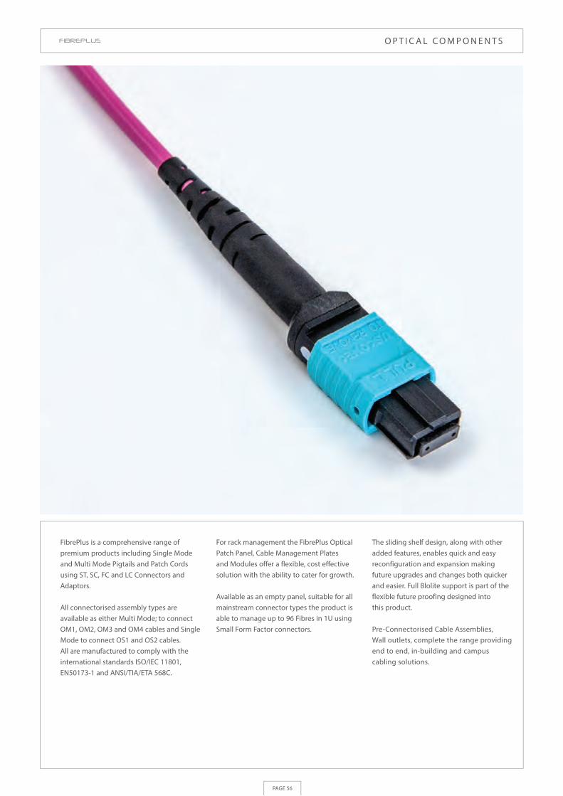
PAGE 56
FibrePlus is a comprehensive range of premium products including Single Mode and Multi Mode Pigtails and Patch Cords using ST, SC, FC and LC Connectors and Adaptors.
All connectorised assembly types are available as either Multi Mode; to connect OM1, OM2, OM3 and OM4 cables and Single Mode to connect OS1 and OS2 cables. All are manufactured to comply with the international standards ISO/IEC 11801, EN50173-1 and ANSI/TIA/ETA 568C.
For rack management the FibrePlus Optical Patch Panel, Cable Management Plates and Modules offer a flexible, cost effective solution with the ability to cater for growth.
Available as an empty panel, suitable for all mainstream connector types the product is able to manage up to 96 Fibres in 1U using Small Form Factor connectors.
The sliding shelf design, along with other added features, enables quick and easy reconfiguration and expansion making future upgrades and changes both quicker and easier. Full Blolite support is part of the flexible future proofing designed into this product.
Pre-Connectorised Cable Assemblies, Wall outlets, complete the range providing end to end, in-building and campus cabling solutions.
O P T I C A L C O M P O N E N T S

Brand-Rex product datasheets contain detailed information on each product’s physical characteristics, electrical parameters and performance data. The most up to date datasheets can be found at www.brand-rex.com/datasheet
PAGE 57
AC
CE
SS
OR
IES
BC
AB
INET
S
Manufactured to comply with: ISO/IEC 11801,EN50173 -1, ANSI TIA/EIA 568.C
Manufactured to comply with: ISO/IEC 11801,EN50173 -1, ANSI TIA/EIA 568.C
FC - FC Duplex
LC - SC Duplex
LC - ST Duplex
LC - LC Duplex
MT-RJ - SC Duplex
SC - SC Duplex
SC - ST Duplex
ST - ST Duplex
HOPFC062010FC291
HOPLC062010SC293
HOPLC062010ST293
HOPLC062010LC293
HOPMJ062010SC292
HOPSC062010SC291
HOPSC062010ST291
HOPST062010ST291
HOPFC062020FC291
HOPLC062020SC293
HOPLC062020ST293
HOPLC062020LC293
HOPMJ062020SC292
HOPSC062020SC291
HOPSC062020ST291
HOPST062020ST291
HOPFC062030FC291
HOPLC062030SC293
HOPLC062030ST293
HOPLC062030LC293
HOPMJ062030SC292
HOPSC062030SC291
HOPSC062030ST291
HOPST062030ST291
HOPFC062050FC291
HOPLC062050SC293
HOPLC062050ST293
HOPLC062050LC293
HOPMJ062050SC292
HOPSC062050SC291
HOPSC062050ST291
HOPST062050ST291
1m 2m 3m 5m
62.5/125 OM1 Multi Mode Optical Patch Cords
50/125 OM2 Multi Mode Optical Patch Cords
For use in permanent connections between transmission equipment and patch panels or interconnect / cross connect between panels. Patch cords are pre-constructed with connectors. These include small form factors such as LC and MT-RJ as well as SC, FC and ST. Based on 2.80mm sub units (1.9mm SFF) these cables are sheathed with LSHF material making them suitable for internal use.
For use in permanent connections between transmission equipment and patch panels or interconnect / cross connect between panels. Patch cords are pre-constructed with connectors. These include small form factors such as LC and MT-RJ as well as SC, FC and ST. Based on 2.80mm sub units (1.9mm SFF) these cables are sheathed with LSHF material making them suitable for internal use.
1m 2m 3m 5m
FC - FC Duplex
LC - SC Duplex
LC - ST Duplex
LC - LC Duplex
SC - SC Duplex
SC - ST Duplex
ST - ST Duplex
HOPFC050010FC291
HOPLC050010SC293
HOPLC050010ST293
HOPLC050010LC293
HOPSC050010SC291
HOPSC050010ST291
HOPST050010ST291
HOPFC050020FC291
HOPLC050020SC293
HOPLC050020ST293
HOPLC050020LC293
HOPSC050020SC291
HOPSC050020ST291
HOPST050020ST291
HOPFC050030FC291
HOPLC050030SC293
HOPLC050030ST293
HOPLC050030LC293
HOPSC050030SC291
HOPSC050030ST291
HOPST050030ST291
HOPFC050050FC291
HOPLC050050SC293
HOPLC050050ST293
HOPLC050050LC293
HOPSC050050SC291
HOPSC050050ST291
HOPST050050ST291
O P T I C A L C O M P O N E N T S
For use in permanent connections between transmission equipment and patch panels or interconnect / cross connect between panels. Patch cords are pre-constructed with connectors. These include small form factors such as LC and MT-RJ as well as SC, FC and ST. Based on 2.80mm sub units (1.9mm SFF) these cables are sheathed with LSHF material making them suitable for internal use.
Note: Image shows an LC-LC duplex assembly
Note: Image shows an LC-LC duplex assembly

Brand-Rex product datasheets contain detailed information on each product’s physical characteristics, electrical parameters and performance data. The most up to date datasheets can be found at www.brand-rex.com/datasheet
PAGE 58
Manufactured to comply with: ISO/IEC 11801, EN50173 -1, ANSI TIA/EIA 568B
Manufactured to comply with: ISO/IEC 11801,EN50173 -1, ANSI TIA/EIA 568.C
FC - FC Duplex
LC - SC Duplex
LC - ST Duplex
LC - LC Duplex
LC-LC Duplex Uniboot (BI)*
SC - SC Duplex
SC - ST Duplex
ST - ST Duplex
1m 2m 3m 5m
50/125 OM3 Multi Mode Optical Patch Cords
50/125 OM4 Multi Mode Optical Patch Cords
For use in permanent connections between transmission equipment and patch panels or interconnect / cross connect between panels. Patch cords are pre-constructed with connectors. These include small form factors such as LC and MT-RJ as well as SC, FC and ST. Based on 2.80mm sub units (1.9mm SFF) these cables are sheathed with LSHF material making them suitable for internal use.
For use in permanent connections between transmission equipment and patch panels or interconnect / cross connect between panels. Patch cords are pre-constructed with connectors. These include small form factors such as LC and MT-RJ as well as SC, FC and ST. Based on 2.80mm sub units (1.9mm SFF) these cables are sheathed with LSHF material making them suitable for internal use.
1m 2m 3m 5m
FC - FC Duplex
LC - SC Duplex
LC - ST Duplex
LC - LC Duplex
SC - SC Duplex
SC - ST Duplex
ST - ST Duplex
HOPFCOM3010FC251
HOPLCOM3010SC253
HOPLCOM3010ST253
HOPLCOM3010LC253
BOPLCOM3010LC257
HOPSCOM3010SC251
HOPSCOM3010ST251
HOPSTOM3010ST251
HOPFCOM3020FC251
HOPLCOM3020SC253
HOPLCOM3020ST253
HOPLCOM3020LC253
BOPLCOM3020LC257
HOPSCOM3020SC251
HOPSCOM3020ST251
HOPSTOM3020ST251
HOPFCOM3030FC251
HOPLCOM3030SC253
HOPLCOM3030ST253
HOPLCOM3030LC253
BOPLCOM3030LC257
HOPSCOM3030SC251
HOPSCOM3030ST251
HOPSTOM3030ST251
HOPFCOM3050FC251
HOPLCOM3050SC253
HOPLCOM3050ST253
HOPLCOM3050LC253
BOPLCOM3050LC257
HOPSCOM3050SC251
HOPSCOM3050ST251
HOPSTOM3050ST251
HOPFCOM4010FC271
HOPLCOM4010SC273
HOPLCOM4010ST273
HOPLCOM4010LC273
HOPSCOM4010SC271
HOPSCOM4010ST271
HOPSTOM4010ST271
HOPFCOM4020FC271
HOPLCOM4020SC273
HOPLCOM4020ST273
HOPLCOM4020LC273
HOPSCOM4020SC271
HOPSCOM4020ST271
HOPSTOM4020ST271
HOPFCOM4030FC271
HOPLCOM4030SC273
HOPLCOM4030ST273
HOPLCOM4030LC273
HOPSCOM4030SC271
HOPSCOM4030ST271
HOPSTOM4030ST271
HOPFCOM4050FC271
HOPLCOM4050SC273
HOPLCOM4050ST273
HOPLCOM4050LC273
HOPSCOM4050SC271
HOPSCOM4050ST271
HOPSTOM4050ST271
O P T I C A L C O M P O N E N T S
For use in permanent connections between transmission equipment and patch panels or interconnect / cross connect between panels. Patch cords are pre-constructed with connectors. These include small form factors such as LC and MT-RJ as well as SC, FC and ST. Based on 2.80mm sub units (1.9mm SFF) these cables are sheathed with LSHF material making them suitable for internal use.
For use in permanent connections between transmission equipment and patch panels or interconnect / cross connect between panels. Patch cords are pre-constructed with connectors. These include small form factors such as LC and MT-RJ as well as SC, FC and ST. Based on 2.80mm sub units (1.9mm SFF) these cables are sheathed with LSHF material making them suitable for internal use.
Note: Image shows an LC-LC duplex assembly
Note: Image shows an LC-LC duplex assembly * Bend Insensitive Uniboot patch cord

Brand-Rex product datasheets contain detailed information on each product’s physical characteristics, electrical parameters and performance data. The most up to date datasheets can be found at www.brand-rex.com/datasheet
PAGE 59
AC
CE
SS
OR
IES
BC
AB
INET
S
Manufactured to comply with: ISO/IEC 11801,EN50173 -1, ANSI TIA/EIA 568.C
Manufactured to comply with: ISO/IEC 11801,EN50173 -1, ANSI TIA/EIA 568.C
1m
1m
2m
2m
3m
3m
5m
5m
Single Mode Optical Patch Cords
Single Mode and Multi Mode Optical Pigtails
For use in permanent connections between transmission equipment and patch panels or interconnect / cross connect between panels. Patch cords are pre-constructed with connectors. These include small form factors such as LC, SC, FC and ST. Based on 2.80mm sub units (1.9mm SFF) these cables are sheathed with LSHF material making them suitable for internal use.
For use in permanent connections between patch panels and incoming cables / single blown fibres. Pigtails are pre-constructed with connectors. Connector options include small form factors such as LC as well as SC, FC and ST. Based on 900µm tight buffered cores (600µm SFF) and suitable for internal use only inside suitable Fibre Management Systems.
OM1
OM1
OM2
OM2
OM3
OM3
OM4
OM4
OMS1/OS2
OMS1/OS2
HOPFC008010FC201
HOPLC008010SC203
HOPLC008010ST203
HOPLC008010LC203
HOPSC008010SC201
HOPSC008010ST201
HOPST008010ST201
HOPAC008010AC201
HOPAL008010AC203
HOPAL008010AL203
HOPUC008010UC201
HOPUL008010UC203
HOPUL008010UL203
HOPFC008020FC201
HOPLC008020SC203
HOPLC008020ST203
HOPLC008020LC203
HOPSC008020SC201
HOPSC008020ST201
HOPST008020ST201
HOPAC008020AC201
HOPAL008020AC203
HOPAL008020AL203
HOPUC008020UC201
HOPUL008020UC203
HOPUL008020UL203
HOPFC008030FC201
HOPLC008030SC203
HOPLC008030ST203
HOPLC008030LC203
HOPSC008030SC201
HOPSC008030ST201
HOPST008030ST201
HOPAC008030AC201
HOPAL008030AC203
HOPAL008030AL203
HOPUC008030UC201
HOPUL008030UC203
HOPUL008030UL203
HOPFC008050FC201
HOPLC008050SC203
HOPLC008050ST203
HOPLC008050LC203
HOPSC008050SC201
HOPSC008050ST201
HOPST008050ST201
HOPAC008050AC201
HOPAL008050AC203
HOPAL008050AL203
HOPUC008050UC201
HOPUL008050UC203
HOPUL008050UL203
FC - FC Duplex
LC - SC Duplex
LC - ST Duplex
LC - LC Duplex
SC - SC Duplex
SC - ST Duplex
ST - ST Duplex
SC/APC-SC/APC Duplex*
LC/APC-SC/APC Duplex
LC/APC-LC/APC Duplex
SC/UPC-SC/UPC Duplex*
LC/UPC-SC/UPC Duplex
LC/UPC-LC/UPC Duplex
FC - 1 metre
SC - 1 metre
ST - 1 metre
LC - 1 metre
SC/APC - 1 meter
LC/APC - 1 meter
SC/UPC - 1 meter
LC/UPC - 1 meter
FC - 2 metre
SC - 2 metre
ST - 2 metre
LC - 2 metre
MT-RJ - 2 metre
SC/APC - 2 meter
LC/APC - 2 meter
SC/UPC - 2 meter
LC/UPC - 2 meter
HOTFC062001
HOTSC062001
HOTST062001
HOTLC062001
-
-
-
-
HOTFC062002
HOTSC062002
HOTST062002
HOTLC062002
HOTMJ062502
-
-
-
-
HOTFC050001
HOTSC050001
HOTST050001
HOTLC050001
-
-
-
-
HOTFC050002
HOTSC050002
HOTST050002
HOTLC050002
HOTMJ050502
-
-
-
-
HOTFCOM3001
HOTSCOM3001
HOTSTOM3001
HOTLCOM3001
-
-
-
-
HOTFCOM3002
HOTSCOM3002
HOTSTOM3002
HOTLCOM3002
HOTMJOM3502
-
-
-
-
HOTFC008001
HOTSC008001
HOTST008001
HOTLC008001
HOTAC008001
HOTAL008001
HOTUC008001
HOTUL008001
HOTFC008002
HOTSC008002
HOTST008002
HOTLC008002
-
HOTAC008002
HOTAL008002
HOTUC008002
HOTUL008002
HOTFCOM4001
HOTSCOM4001
HOTSTOM4001
HOTLCOM4001
-
-
-
-
HOTFCOM4002
HOTSCOM4002
HOTSTOM4002
HOTLCOM4002
HOTMJOM4502
-
-
-
-
O P T I C A L C O M P O N E N T S
For use in permanent connections between transmission equipment and patch panels or interconnect / cross connect between panels. Patch cords are pre-constructed with connectors. These include small form factors such as LC, SC, FC and ST. Based on 2.80mm sub units (1.9mm SFF) these cables are sheathed with LSHF material making them suitable for internal use.
FC - FC Duplex
LC - SC Duplex
Note: Image shows an LC-LC duplex assembly Single Mode Optical Patch Cords
Single Mode O *= also available as 10m ptical Patch Cords
Pigtail OM4
Pigtail SM
Pigtail OM3

Brand-Rex product datasheets contain detailed information on each product’s physical characteristics, electrical parameters and performance data. The most up to date datasheets can be found at www.brand-rex.com/datasheet
PAGE 60
FibrePlus - Unloaded Panels & Panel Options
The FibrePlus 1U fibre 19” Optic Patch Panels have been designed to optimise both the internal fibre management but also to add greater fibre density. Constructed from mild steel with a powder coated paint finish the panels are available in Black or Grey. The Patch Panels offers a flexible and highly versatile solution for optical splicing and patching. The panel’s shallow depth allows it to be installed within the majority of standard racks and wall mounted enclosures. The integrated design features ensure that even once installed panels can be readily re-configured to accommodate the changing needs of today’s high speed networks.
FPCC1SXXX24ST2
FPCC1SXXX24DC2
FPCC1SXXX48DC2
FPCC1SXXX48SC2
FPCFMKIT001
30-0301-5
BPEST101-100
BPESC101-100
BPESC301-100
30-4800-09
Unloaded Optical for up to 24 ST or FC adaptors - Black
Unloaded Optical for up to 12 SC Duplex or LC Quad adaptors - Black
Unloaded Optical for up to 24 SC Duplex or LC Quad adaptors - Black
Unloaded Optical for up to 24 SC Simplex, MT-RJ & LC Duplex adaptors - Black
Fibre management kit including loops and 24 way splice bridge
Adaptor collar for 3mm Straight connector
ST/FC Blanking Plugs (Black) - Pack 100
SC Simplex Blanking Plug (also suitable for LC & MT -RJ) (Black) - Pack 100
SC Duplex Blanking Plug (also suitable for LC Quad) (Black) - Pack 100
25mm Manifold Gland
Part NumberDescription
O P T I C A L C O M P O N E N T S
FibrePlus - Part Loaded Patch Panels
The FibrePlus 19” 1U fibre Optic Patch Panels have been designed to optimise both the internal fibre management but also to add greater fibre density. Constructed from mild steel with a powder coated paint finish the panels are available in Black or Grey. The Patch Panels offers a flexible and highly versatile solution for optical splicing and patching. The panel’s shallow depth allows it to be installed within the majority of standard racks and wall mounted enclosures. The integrated design features ensure that even once installed panels can be readily re-configured to accommodate the changing needs of today’s high speed networks.
Description
ST Single Mode
ST Multi Mode
FC Single Mode
SC Duplex - Single Mode
SC Duplex - Multi Mode
SC Simplex Single Mode
SC Simplex Multi Mode
LC Duplex Single Mode
LC Duplex Multi Mode
LC Quad Single Mode
LC Quad Multi Mode
FPCC1SXSM04ST2
FPCC1SXMM04ST2
FPCC1SXSM04FC2
FPCC1SXSM08DC2
FPCC1SXMM08DC2
FPCC1SXSM04SC2
FPCC1SXMM04SC2
FPCC1SXSM08LC2
FPCC1SXMM08LC2
-
-
4 Adaptor
FPCC1SXSM06ST2
FPCC1SXMM06ST2
FPCC1SXSM06FC2
FPCC1SXSM12DC2
FPCC1SXMM12DC2
FPCC1SXSM06SC2
FPCC1SXMM06SC2
FPCC1SXSM12LC2
FPCC1SXMM12LC2
-
-
6 Adaptor
FPCC1SXSM08ST2
FPCC1SXMM08ST2
FPCC1SXSM08FC2
FPCC1SXSM16DC2
FPCC1SXMM16DC2
FPCC1SXSM08SC2
FPCC1SXMM08SC2
FPCC1SXSM16LC2
FPCC1SXMM16LC2
-
-
8 Adaptor
FPCC1SXSM12ST2
FPCC1SXMM12ST2
FPCC1SXSM12FC2
FPCC1SXSM24DC2
FPCC1SXMM24DC2
FPCC1SXSM12SC2
FPCC1SXMM12SC2
FPCC1SXSM24LC2
FPCC1SXMM24LC2
-
-
12 Adaptor
FPCC1SXSM16ST2
FPCC1SXMM16ST2
FPCC1SXSM16FC2
FPCC1SXSM32DC2
FPCC1SXMM32DC2
FPCC1SXSM16SC2
FPCC1SXMM16SC2
FPCC1SXSM32LC2
FPCC1SXMM32LC2
-
-
16 Adaptor
FPCC1SXSM24ST2
FPCC1SXMM24ST2
FPCC1SXSM24FC2
FPCC1SXSM48DC2
FPCC1SXMM48DC2
FPCC1SXSM24SC2
FPCC1SXMM24SC2
FPCC1SXSM48LC2
FPCC1SXMM48LC2
FPCC1SXSM96LC2
FPCC1SXMM96LC2
24 Adaptor

Brand-Rex product datasheets contain detailed information on each product’s physical characteristics, electrical parameters and performance data. The most up to date datasheets can be found at www.brand-rex.com/datasheet
PAGE 61
AC
CE
SS
OR
IES
BC
AB
INET
S
High Density Fibre Management Panel
The High Density Fibre Management Panel offers the ultimate solution for management of fibre in Data Centres and telecoms rooms. The panel combines a robust metal frame with precision injection moulded plastic to deliver a flexible and secure construction while still offering fully integrated and flexible fibre management. The 1U 48 LC port patch panel facilitates patch cord routing directly into the rack vertical side management, thus increasing rack density and easing undue stresses on the cords. It is designed to pivot and hinge providing the control and security of a fixed panel but also allowing for increased access and usability.
O P T I C A L C O M P O N E N T S
Part NumberDescription
High Density Fibre Management Panel, 48 LC Ports, 1U Dual cassette, part loaded with
12 x Quad LC Multi-mode adaptors & glands - Black
High Density Fibre Management Panel, 48 LC Ports, 1U Dual cassette, part loaded with
12 x Quad LC Single-mode adaptors & glands - Black
FPCPC1XMM48LC2
FPCPC1XSM48LC2
FibrePlus Dual Pivoting Patch Panel
The 48 �bre universal dual pivoting patch panel provides easy segregation of �bres, perfect for separating services. The unique design o�ers features, such as the swivel function in a universal 19” size, normally only found in bespoke solutions. It is simple to manage and o�ers easy access in the event of moves, adds or changes.
The dual cassette design pivots from the left and right allowing the patch cords to exit the panel from the two sides giving fast access to the �bre management whilst maintaining a �xed cable entry point. Easy to install lightweight and robust construction, the transparent cover protects the �bre and allows quick and easy access.
Part NumberDescription
19” Optical Dual Pivoting Panel (1U)- populated with Single-Mode flangeless LC Quad adaptors
19” Optical Dual Pivoting Panel (1U)- populated with Multi-Mode flangeless LC Quad adaptors
19” Optical Dual Pivoting Panel (1U) – unpopulated
TCCPC1SM48LC2
TCCPC1MM48LC2
TCCPC1XXXXXX2
45mm x 45mm and 50mm x 50mm Faceplate Modules
The Brand-Rex range of 45 x 45 Fibre faceplate modules is designed for use in installation poles, wall trunking and back boxes. Configurations are available for Euro style 45 x 45mm faceplates and UK style 50 x 50mm versions offering a versatile solution.
Part NumberDescription
FPCANGLCMM3
FPCANGLCSM3
FPCANGL4MM3
FPCANGL4SM3
FPCANGDCMM3
FPCANGDCSM3
FPCANGLCMM3UK
FPCANGLCSM3UK
FPCANGL4MM3UK
FPCANGL4SM3UK
FPCANGDCMM3UK
FPCANGDCSM3UK
MMCWDOUNI031
MMCDGBB44002
MMCWDOUNI030
MMCSGBB44001
45w x 45 mm Fibre Faceplate Module LC Duplex Multi Mode
45 x 45 mm Fibre Faceplate Module LC Duplex Single Mode
45 x 45 mm Fibre Faceplate Module LC Quad Multi Mode
45 x 45 mm Fibre Faceplate Module LC Quad Single Mode
45 x 45 mm Fibre Faceplate Module SC Duplex Multi Mode
45 x 45 mm Fibre Faceplate Module SC Duplex Single Mode
50 x 50 mm Fibre Faceplate Module LC Duplex Multi Mode
50 x 50 mm Fibre Faceplate Module LC Duplex Single Mode
50 x 50 mm Fibre Faceplate Module LC Quad Multi Mode
50 x 50 mm Fibre Faceplate Module LC Quad Single Mode
50 x 50 mm Fibre Faceplate Module SC Duplex Multi Mode
50 x 50 mm Fibre Faceplate Module SC Duplex Single Mode
86 x 147 mm Double Gang Modular Faceplate
44 mm Deep Double Gang UK Back Box
86 x 86mm Single Gang Modular Faceplate
44mm Deep Back Box
FPCANGL4MM3UK
FPCANGDCMM3UK

Brand-Rex product datasheets contain detailed information on each product’s physical characteristics, electrical parameters and performance data. The most up to date datasheets can be found at www.brand-rex.com/datasheet
PAGE 62
Description
SC Simplex AdaptorSC Adaptors comprise of a polymer outer body and inner assembly fitted with a precision alignment sleeve. Multimode with metal sleeve. Single mode with ceramic sleeve.
O P T I C A L C O M P O N E N T S
SC Optical Connectors
SC Simplex and Duplex ConnectorsSC multimode and single mode connector kits comprise of a one piece SC body with precision ceramic ferrule, crimp, sleeve, colour coded outer shroud, 2 x colour coded 3mm strain relief boots and a 0.9mm boot. SC Duplex connector kits comprise of 2 simplex connectors mounted in a two piece polymer clip and 2 x colour coded 3mm strain relief boots.
SC Duplex AdaptorSC Duplex adaptors comprise of a polymer outer body and an inner assembly fitted with a precision alignment sleeve. Multimode with metal sleeve. Single mode with ceramic sleeve.
Connector Adaptor
BHCSCMM001
BHCSCSM001
BHCDCMM001
BHCDCSM001
SC - MultiMode (Beige)
SC - Single Mode (Blue)
SC Duplex - Multi Mode (Beige)
SC Duplex - Single Mode (Blue)
FOCSCEPMM001
FOCSCEPSM001
FOCDCEPMM001
FOCDCEPSM001
Description
ST AdaptorST adaptors comprise of a nickel plated zinc die cast body with a precision alignment sleeve. They are both standard and double ‘D’ hole compatible. Multimode with metal sleeve. Single mode with ceramic sleeve.
ST, FC Optical Connectors
ST ConnectorST connector kits comprise of a nickel plated zinc coupling body with a precision ceramic ferrule, crimp sleeve, 2 x colour coded 3mm strain reliefs and a 0.9mm boot.
FC AdaptorFC adaptors comprise of a nickel plated brass body that is fitted with a precision alignment sleeve. They are standard single and double ‘D’ hole compatible.
Connector Adaptor
FOCSTEPMM001
FOCSTEPSM001
FOCFCEPSM001
BHCSTMM001
BHCSTSM001
BHCFCSM001
ST - Multi Mode
ST Single Mode
FC-PC Single Mode

Brand-Rex product datasheets contain detailed information on each product’s physical characteristics, electrical parameters and performance data. The most up to date datasheets can be found at www.brand-rex.com/datasheet
PAGE 63
AC
CE
SS
OR
IES
BC
AB
INET
S
Description
O P T I C A L C O M P O N E N T S
LC Optical Connectors
Connector Adaptor
The range of Brand-Rex SFF (Small Form Factor) connectivity solutions are reliable and robust, quality products. SFF connectors are duplex fibre connectors which have a footprint similar to RJ-45's, offering the system integrator / installer an improved patching density, saving valuable rack space. The products can be used at the panel or in the work area supporting both backbone fibre and fibre to the desk solutions. Brand-Rex offers a choice of leading, de-facto, SFF connectors, the MT-RJ and the LC.
LC Connector:LC multimode and single mode connector kits comprise of a precision ferrule, crimp sleeve, colour coded outer shroud, 2 x colour coded 2.0mm strain reliefs (..001) or a 0.9mm (..002) boot.
LC Duplex Adaptor:LC adaptors (BHCLCXM001) comprise of a polymer body with a a precision alignment sleeve. They have the outer dimensions of a simplex SC style adaptor.
LC Quad Adaptor:LC adaptors (BHCL4XM001) comprise of a polymer body with precision alignment sleeves. They have the outer dimensions of a duplex SC style adaptor.
FOCLCEPMM001
FOCLCEPSM001
FOCLSEPMM001
FOCLSEPSM001
FOCLSEPMM002
FOCLSEPSM002
-
-
-
BHCLCMM001
BHCLCSM001
-
-
-
-
BHCL4MM001
BHCL4SM001
BHCMJXX001
LC Multimode (Duplex) (Beige)
LC Single Mode (Duplex) (Blue)
LC Multimode (Simplex) (Beige)
LC Single Mode (Simplex) (Blue)
LC Multimode (Simplex Pigtail) (Beige)
LC Single Mode (Simplex Pigtail) (Blue)
LC Multimode (Quad) Beige
LC Single Mode (Quad) (Blue)
MT RJ adaptor

Brand-Rex product datasheets contain detailed information on each product’s physical characteristics, electrical parameters and performance data. The most up to date datasheets can be found at www.brand-rex.com/datasheet
PAGE 64
KeyQuick® Mechanical Splice is an innovative, quick and easy to use mechanical splice. The full field termination solution includes mechanical splice and splice holders as well as universal connectors and is designed to offer installers a fast, accurate and user friendly splicing process.
Secure LC Patch Cord System
The Secure Lock system comprises of a secure patch cord, blank adaptor plug and extraction tool. The Secure LC patch cord prevents unauthorised port access or changes as it can only be removed using a unique keyed extraction tool, making it ideal for creating a secure area within Data centres and IT networks. The Duplex LC patch cords will plug into any industry compliant Duplex and Quad adaptors or active interfaces. The locking plug closes off ports, restricting access and offering dust protection. When fitted, the plug can only be removed with the correct the tool. The keyed extraction tool unlocks and releases the connectors from ports. Keys are available for custom applications and can be customised to only release the same coloured LC connector or blank adapter plug.
O P T I C A L C O M P O N E N T S
* zzz= connector colour - Red (001), Black (002), White (003), Green (005), Yellow (006), Grey (008), Orange (009), Aqua (051).** Part is also available for custom applications with Key colour matched to the connector colour
1m
2m
3m
5m
1m
2m
3m
5m
1m
2m
3m
5m
n/a
n/a
OLPLC008010LCzzz
OLPLC008020LCzzz
OLPLC008030LCzzz
OLPLC008050LCzzz
OLPLCOM3010LCzzz
OLPLCOM3020LCzzz
OLPLCOM3030LCzzz
OLPLCOM3050LCzzz
OLPLCOM4010LCzzz
OLPLCOM4020LCzzz
OLPLCOM4030LCzzz
OLPLCOM4050LCzzz
OLCLCBLK-xxx
OLCLCTOOL-015
LC Duplex Single Mode Secure Patch Cord
LC Duplex Single Mode Secure Patch Cord
LC Duplex Single Mode Secure Patch Cord
LC Duplex Single Mode Secure Patch Cord
LC Duplex OM3 Multimode Secure Patch Cord
LC Duplex OM3 Multimode Secure Patch Cord
LC Duplex OM3 Multimode Secure Patch Cord
LC Duplex OM3 Multimode Secure Patch Cord
LC Duplex OM4 Multimode Secure Patch Cord
LC Duplex OM4 Multimode Secure Patch Cord
LC Duplex OM4 Multimode Secure Patch Cord
LC Duplex OM4 Multimode Secure Patch Cord
Secure Patch Cord Blank Adaptor Plug
Secure Patch Cord Master Extraction Key (Violet)**
Part Number*LengthDescription
Before connection
KeyQuick® Mechanical Splice
Part NumberDescription
KeyQuick® Mechanical Splice 250µm, 900µm
KeyQuick® Mechanical Splice Holder
FPCMS001
FPCMSH06
Splice HolderAfter connection
KeyQuick® KQ10 Field Installable Connectors
KeyQuick® Field Installable KQ10 Connectors offer an innovative solution for onsite connector terminations. The SC connectors are ideal for backbone, horizontal and FTTH applications, offering an easy, fast, accurate and user friendly connector splicing process.
Part NumberDescription
Before connection After connection
KeyQuick® SC APC Single Mode Connector - Universal G652D
KeyQuick® SC UPC Single Mode Connector - Universal G652D
KeyQuick® SC UPC Multimode Connector - Universal 62.5/125
KeyQuick® SC UPC Multimode Connector - Universal 50/125 OM3
KeyQuick® SC UPC Multimode Connector - Universal 50/125 OM4
FOCACFT008001
FOCUCFT008001
FOCUCFT062001
FOCUCFTOM3001
FOCUCFTOM4001

PAGE 65
AC
CE
SS
OR
IES
BC
AB
INET
SC
AB
INET
S
Customer requirements in the ever-advancing communications market continues to grow, stretching scarce bandwidth resources and truly testing the performance of today’s networks.
In choosing cabling system solutions, whether for small, medium or large multi site locations, server farms or co-location datacentres, network planners have some serious issues to consider. Among these is the decision as to which type and mix of fibre to install to allow for network expansion and upgrades which has been a dilemma for many years.
In the past, industry practice has been to install ‘dark fibre’ to meet future demands, however, this strategy is by no means risk-free as unterminated, untested fibres may not be fit for purpose when the time comes to light the fibres in the future. Fortunately there is a simple and cost effective solution - Brand-Rex Air Blown Fibre Systems offer solutions for both Internal and External applications with their market leading Blolite and MicroBlo. The use of Air Blown Fibre Systems gives complete freedom from risk by pre-installing a ducting route and then blowing in the fibre element (and paying for it) only when required.
The Blolite system was one of the first Air Blown Fibre systems, it is also regarded as the 'industry standard' Air Blown Fibre System. The Blolite system is very versatile with backbone and / or fibre to the desk links and can even allow for long distance links of up to 1km. Blolite is easily installed, by using compressed air, there is no disruption to the workplace, Blolite fibres are simply terminated and are compatible with all standard optical connectors.
Blolite is also extremely reliable, with a zero failure rate since the first installations in 1988 - truly an 'insurance policy' for high speed networks. It is no surprise that major users such as Manchester Airport, IBM, Ericsson, GlaxoSmithKline (GSK), the British MoD, Aerospatiale, Pfizer and even the US Navy have taken advantage of the system.
A I R B L O W N F I B R E S Y S T E M S

Brand-Rex product datasheets contain detailed information on each product’s physical characteristics, electrical parameters and performance data. The most up to date datasheets can be found at www.brand-rex.com/datasheet
PAGE 66
Blolite Internal MultiDucts
To facilitate the installation of Blolite single blown fibres a range of multi-way MicroDucts into which Blolite fibres can be blown are availible. The internal range of these MicroDucts are constructed with the standard Blolite MicroDuct surrounded with a layer of polyester tape and a LSHF outer sheath making them suitable for internal applications.
A I R B L O W N F I B R E S Y S T E M S
Microduct size = 3/2.1mm
Microduct size = 5/3.5mm
Microduct size = 8/6mm
Part Number
Part Number
Part Number
Description
Description
Description
1w 3/2.1mm (PO)-I
4w 3/2.1mm (PO)-I
7w 3/2.1mm (PO)-I
12w 3/2.1mm (PO)-I
19w 3/2.1mm (PO)-I
BL01IN0321
BL04IN0321
BL07IN0321
BL12IN0321
BL19IN0321
5.0
9.3
11.7
15.2
17.7
Diameter (mm)
Diameter (mm)
Diameter (mm)
BL01IN0535
BL02IN0535
BL04IN0535
BL07IN0535
BL12IN0535
BL19IN0535
1w 5/3.5mm (LSHF)-I
2w 5/3.5mm (LSHF)-I
4w 5/3.5mm (LSHF)-I
7w 5/3.5mm (LSHF)-I
12w 5/3.5mm (LSHF)-I
19w 5/3.5mm (LSHF)-I
5.0
7.5 x 13.0
15.2
18.6
24.0
29.6
BL01IN0806
BL02IN0806
BL04IN0806
BL07IN0806
BL12IN0806
8.0
10.5 x 19.0
23.0
27.6
36.0
1w 8/6mm (LSHF)-I
2w 8/6mm (LSHF)-I
4w 8/6mm (LSHF)-I
7w 8/6mm (LSHF)-I
12w 8/6mm (LSHF)-I
Blolite Single Blown Fibre Elements
The Blolite system offers a complete range of high quality single mode and multimodeoptical fibres, with a blowable coating and fibre, is strippable with standard tools and iscompatible with standard connector types. Blolite fibre is available in twelve standard coloursand is supplied on plastic spools in 2km or 4km lengths for installation into Blolite 3mm, 5mmand 8mm MicroDuct by trained and licensed Blolite installers using the IM2000 blow head.
OM1 OM2 OM3 OS1/OS2OM4
White
Black
Blue
Orange
Green
Red
Grey
Yellow
Brown
Violet
Pink
Turquoise
10-0101-03
10-0101-05
10-0101-06
10-0101-07
10-0101-08
10-0101-09
10-0101-10
10-0101-11
10-0101-12
10-0101-13
10-0101-14
10-0101-15
10-0005-03
10-0005-05
10-0005-06
10-0005-07
10-0005-08
10-0005-09
10-0005-10
10-0005-11
10-0005-12
10-0005-13
10-0005-14
10-0005-15
10-0003-03
10-0003-05
10-0003-06
10-0003-07
10-0003-08
10-0003-09
10-0003-10
10-0003-11
10-0003-12
10-0003-13
10-0003-14
10-0003-15
10-0200-03
10-0200-05
10-0200-06
10-0200-07
10-0200-08
10-0200-09
10-0200-10
10-0200-11
10-0200-12
10-0200-13
10-0200-14
10-0200-15
10-0004-03
10-0004-05
10-0004-06
10-0004-07
10-0004-08
10-0004-09
10-0004-10
10-0004-11
10-0004-12
10-0004-13
10-0004-14
10-0004-15

Brand-Rex product datasheets contain detailed information on each product’s physical characteristics, electrical parameters and performance data. The most up to date datasheets can be found at www.brand-rex.com/datasheet
PAGE 67
AC
CE
SS
OR
IES
BC
AB
INET
SC
AB
INET
S
Blolite Direct Intall MultiDucts
To facilitate the installation of Blolite single blown fibres a range of multi-way MicroDucts into which Blolite fibres can be blown are available. The external range of these MultiDucts are constructed with the standard Blolite MicroDuct surrounded with a layer of Polyester tape and a Polyethylene outer sheath making them suitable for direct install applications.
Part Number
Part Number
Description
Description
Diameter (mm)
Diameter (mm)
Microduct size = 5/3.5mm
Microduct size = 8/6mm
7.5
7.5 x 13.0
15.2
18.6
24.0
29.6
BL01DI0535
BL02DI0535
BL04DI0535
BL07DI0535
BL12DI0535
BL19DI0535
1w 5/3.5mm (LSHF)-O
2w 5/3.5mm (LSHF)-O
4w 5/3.5mm (LSHF)-O
7w 5/3.5mm (LSHF)-O
12w 5/3.5mm (LSHF)-O
19w 5/3.5mm (LSHF)-O
10.5
10.5 x 19.0
23.0
27.6
36.0
1w 8/6mm (LSHF)-O
2w 8/6mm (LSHF)-O
4w 8/6mm (LSHF)-O
7w 8/6mm (LSHF)-O
12w 8/6mm (LSHF)-O
BL01DI0806
BL02DI0806
BL04DI0806
BL07DI0806
BL12DI0806
OM1 OM2 OM3
OM3
OS1/OS2OM4
OM4
2-12 Fibre Blown Micro Cable
Microduct cabling systems are popular solutions for building flexibility into a network, they can be populated when needed and leave spare capacity for future growth. The ability to defer initial installation costs is a key advantage of an air blown cable installation over traditional cable installations. The MicroBlo air blown loose tube microduct cable is available with fibre counts from 2 to 12 in a 2.5 mm diameter package. The cable has been specifically designed and developed for improved installation efficiency in pre-installed 5/3.5 mm microducts using existing air blown installation techniques.
A I R B L O W N F I B R E S Y S T E M S
2 fibre
4 fibre
6 fibre
8 fibre
12 fibre
HF062BMC2WNM3
HF062BMC4WNM3
HF062BMC6WNM3
HF062BMC8WNM3
HF062BMC12WNM3
HF050BMC2WNM3
HF050BMC4WNM3
HF050BMC6WNM3
HF050BMC8WNM3
HF050BMC12WNM3
HFOM3BMC2WNM3
HFOM3BMC4WNM3
HFOM3BMC6WNM3
HFOM3BMC8WNM3
HFOM3BMC12WNM3
HFOM4BMC2WNM3
HFOM4BMC4WNM3
HFOM4BMC6WNM3
HFOM4BMC8WNM3
HFOM4BMC12WNM3
HF008BMC2WNM3
HF008BMC4WNM3
HF008BMC6WNM3
HF008BMC8WNM3
HF008BMC12WNM3
12-72 Fibre Blown Micro Cable
Microduct cabling systems are popular solutions for building flexibility into a network, they can be populated when needed and leave spare capacity for future growth. The ability to defer initial installation costs is a key advantage of an air blown cable installation over traditional cable installations.
The MicroBlo air blown loose tube microduct cable is available with �bre counts from 12 to 72 in a 6.0 mm diameter package. The micro cable is constructed of a non metallic, resin bonded glass central strength member and high density polyethylene sheath. The cable has been speci�cally designed and developed for improved installation e�ciency in pre-installed 10/8 mm microducts using existing air blown installation techniques. Dry water blocking technology ensures the cable cores are fully water blocked.
OM1 OM2 OS1/OS2
12 fibre
24 fibre
36 fibre
48 fibre
60 fibre
72 fibre
HF062BMC12WNM6
HF062BMC24WNM6
HF062BMC36WNM6
HF062BMC48WNM6
HF062BMC60WNM6
HF062BMC72WNM6
HF050BMC12WNM6
HF050BMC24WNM6
HF050BMC36WNM6
HF050BMC48WNM6
HF050BMC60WNM6
HF050BMC72WNM6
HFOM3BMC12WNM6
HFOM3BMC24WNM6
HFOM3BMC36WNM6
HFOM3BMC48WNM6
HFOM3BMC60WNM6
HFOM3BMC72WNM6
HFOM4BMC12WNM6
HFOM4BMC24WNM6
HFOM4BMC36WNM6
HFOM4BMC48WNM6
HFOM4BMC60WNM6
HFOM4BMC72WNM6
HF008BMC12WNM6
HF008BMC24WNM6
HF008BMC36WNM6
HF008BMC48WNM6
HF008BMC60WNM6
HF008BMC72WNM6

Brand-Rex product datasheets contain detailed information on each product’s physical characteristics, electrical parameters and performance data. The most up to date datasheets can be found at www.brand-rex.com/datasheet
PAGE 68
Up to 96 Fibre Micro Cable
Microduct cabling systems are popular solutions for building flexibility into a network, they can be populated when needed and leave spare capacity for future growth. The ability to defer initial installation costs is a key advantage of an air blown cable installation over traditional cable installations. The MicroBlo air blown loose tube microduct cable is available with fibre counts of 84 and 96 fibres in a 7.0mm diameter package. The cable has been specifically designed and developed for improved installation efficiency in pre-installed 12 /9.4 mm microducts using existing air blown installation techniques. Dry water blocking technology ensures the cable cores are fully water blocked.
Microduct cabling systems are popular solutions for building flexibility into a network, they can be populated when needed and leave spare capacity for future growth. The ability to defer initial installation costs is a key advantage of an air blown cable installation over traditional cable installations. The MicroBlo air blown loose tube microduct cable is available with fibre counts of 84 and 96 fibres in a 7.0mm diameter package. The cable has been specifically designed and developed for improved installation efficiency in pre-installed 12 /9.4 mm microducts using existing air blown installation techniques. Dry water blocking technology ensures the cable cores are fully water blocked.
84 fibre
96 fibres
HF062BMC84WNM8
HF062BMC96WNM8
HF050BMC84WNM8
HF050BMC96WNM8
HFOM3BMC84WNM8
HFOM3BMC96WNM8
HFOM4BMC84WNM8
HFOM4BMC96WNM8
HF008BMC84WNM8
HF008BMC96WNM8
OM1 OM2 OM3 OS1/OS2OM4
MicroBlo Direct Install Protected MicroDucts
Microduct cabling systems are popular solutions for building flexibility into a network, they can be populated when needed and leave spare capacity for future growth. The ability to defer initial installation costs is a key advantage of an air blown cable installation over traditional cable installations.
To facilitate the installation of MicroBlo Microcables, a range of Protected Microducts (multiways) into which Microcables can be blown are available. The Direct Install range of Protected Microducts are constructed with standard individual microducts with a PE sheathing for installation into existing duct and sub-ducting infrastructure.
Microduct size = 5/3.5mm Outer diameter/Bore
Microduct size = 10/8mm Outer diameter/Bore
Microduct size = 12/10mm Outer diameter/Bore
Part Number
Part Number
Part Number
Description
Description
Description
Diameter (mm)
Diameter (mm)
Diameter (mm)
MB01DI0535
MB02DI0535
MB04DI0535
MB07DI0535
MB12DI0535
MB19DI0535
5
11.5
13.6
16.5
21.5
26.5
1W 5/3.5mm
2W 5/3.5mm
4W 5/3.5mm
7W 5/3.5mm
12W 5/3.5mm
19W 5/3.5mm
10
21.5
25.6
31.5
41.5
1W 10/8mm
2W 10/8mm
4W 10/8mm
7W 10/8mm
12W 10/8mm
MB01DI1008
MB02DI1008
MB04DI1008
MB07DI1008
MB12DI1008
1W 12/10mm
2W 12/10mm
4W 12/10mm
7W 12/10mm
MB01DI1210
MB02DI1210
MB04DI1210
MB07DI1210
12
25.5
30
37.5

Brand-Rex product datasheets contain detailed information on each product’s physical characteristics, electrical parameters and performance data. The most up to date datasheets can be found at www.brand-rex.com/datasheet
PAGE 69
AC
CE
SS
OR
IES
BC
AB
INET
SC
AB
INET
S
MicroBlo Direct Burial Protected MicroDucts
Microduct cabling systems are popular solutions for building flexibility into a network, they can be populated when needed and leave spare capacity for future growth. The ability to deferinitial installation costs is a key advantage of an air blown cable installation over traditional cable installations.
To facilitate the installation of MicroBlo Microcables, a range of Protected Microducts (multiways) into which Microcables can be blown are available. The Direct Burial range of Protected Microducts are constructed with thick wall, direct burial individual microducts with an overall HDPE sheathing making them suitable for direct burial applications.
Part Number
Part Number
Part Number
Description
Description
Description
Diameter (mm)
Diameter (mm)
Diameter (mm)
1W 7/3.5mm
2W 7/3.5mm
4W 7/3.5mm
7W 7/3.5mm
12W 7/3.5mm
19W 7/3.5mm
24W 7/3.5mm +1W 14/10mm
MB01DB0735
MB02DB0735
MB04DB0735
MB07DB0735
MB12DB0735
MB19DB0735
MB24DB0735
Microduct size = 7/3.5mm Outer diameter/Bore
7
15.5
18.4
22.5
29.5
36.5
43
1W 12/8mm
2W 12/8mm
4W 12/8mm
7W 12/8mm
MB01DB1208
MB02DB1208
MB04DB1208
MB07DB1208
Microduct size = 12/8mm Outer diameter/Bore
12
25.5
30
37.5
1W 14/10mm
2W 14/10mm
4W 14/10mm
7W 14/10mm
MB01DB1410
MB02DB1410
MB04DB1410
MB07DB1410
Microduct size = 14/10mm Outer diameter/Bore
14
29.5
35
43.5

Brand-Rex product datasheets contain detailed information on each product’s physical characteristics, electrical parameters and performance data. The most up to date datasheets can be found at www.brand-rex.com/datasheet
PAGE 70
MicroBlo Indoor Protected MicroDucts
Microduct cabling systems are popular solutions for building flexibility into a network, they can be populated when needed and leave spare capacity for future growth. The ability to defer initial installation costs is a key advantage of an air blown cable installation over traditional cable installations.
To facilitate the installation of Microblo Microcables, a range of Protected Microducts (multiways) into which Microcables can be blown are available. The Indoor range of Protected Microducts are constructed with Low Smoke Halogen Free microduct which are sheathed with an overall LSHF protective layer. This product is ideal for providing access into a building and can be simply joined to a DI or DB Microduct to allow the cable to be blown straight from outside into the building.
Part Number
Part Number
Part Number
Description
Description
Description
Diameter (mm)
Diameter (mm)
Diameter (mm)
MB01IN0535
MB02IN0535
MB04IN0535
MB07IN0535
MB12IN0535
MB19IN0535
Microduct size = 5/3.5mm Outer diameter/Bore
5
11.5
13.6
16.5
21.5
26.5
1W 10/8mm
2W 10/8mm
4W 10/8mm
7W 10/8mm
12W 10/8mm
MB01IN1008
MB02IN1008
MB04IN1008
MB07IN1008
MB12IN1008
Microduct size = 10/8mm Outer diameter/Bore
10
21.5
25.6
31.5
41.5
1W 12/10mm
2W 12/10mm
4W 12/10mm
7W 12/10mm
MB01IN1210
MB02IN1210
MB04IN1210
MB07IN1210
Microduct size = 12/10mm Outer diameter/Bore
12
25.5
30
37.5
1W 5/3.5mm
2W 5/3.5mm
4W 5/3.5mm
7W 5/3.5mm
12W 5/3.5mm
19W 5/3.5mm

Brand-Rex product datasheets contain detailed information on each product’s physical characteristics, electrical parameters and performance data. The most up to date datasheets can be found at www.brand-rex.com/datasheet
PAGE 71
AC
CE
SS
OR
IES
BC
AB
INET
S
Within MicroBlo and Blolite a range of plastic bodied pneumatic tube connectors are used for tube routing. The connectors have a variety of forms and are all rated for the maximum working pressure of 10 Bar. The connectors are installed with a simple push-pull technique and can be re-used several times.
For Part numbers see next page.
Blolite and MicroBlo Microduct Connectivity
3mm Straight ConnectorFor connecting 2 equal size microducts.
Straight Connector (push-pull mechanism) For connecting 2 equal size microducts.
End PlugFor blocking a straight connector when a later connection is required.
Bulkhead ConnectorFor attaching a microduct to a panel or wall box.
Straight Screw Connector (Screw mechanism)For connecting 2 equal size microducts and eliminating movement at joint.
End StopFor blocking of the end of a redundant tube or temporary sealing.
Gas Blocking ‘T’For use with resin to provide a gas blocking seal where required.
8mm - 5mm ReducerTo reduce from 8mm - 5mm MicroDuct at termination point.
Dust CapFor preventing the ingress of dust during installation.
Termination Splitter / Stem ConverterFor use at the end of a duct route to divert fibres into different termination points.

Brand-Rex product datasheets contain detailed information on each product’s physical characteristics, electrical parameters and performance data. The most up to date datasheets can be found at www.brand-rex.com/datasheet
PAGE 72
50-0506-00
Straight - Push/Pull
Straight - Screw Retention
End Stop
Connector End Plug
Bulkhead Mounted
Connector
Dust Cap
Gas Blocking ‘T’ Piece
8mm to 5mm Reducer
Standard to Direct Burial
mating connector
Termination Fibre Diverter
8mm to 5mm Stem
Converter
Water Blocking Straight
30-0301-00
-
30-0304-00
-
-
30-0307-05
-
-
-
-
-
-
Connector Type 3/2.1 mm 5/3.5 mm 7/3.5 mm 8/6 mm 10/8 mm 12/8 mm 12/9.4 mm 14/9.4 mm
30-0501-00
30-0502-00
30-0504-00
30-0505-09
30-0506-09
30-0507-05
30-0508-00
30-5801-00
-
-
30-5810-05
30-0503-00
30-0721-00
30-0704-00
30-0707-05
30-5701-00
(7/3.5mm to 5/3.5mm)
-
-
-
30-0801-00
30-0802-00
30-0804-00
30-0805-09
-
30-0807-05
30-0808-00
-
-
30-0809-05
-
-
30-1001-00
-
30-1004-00
-
-
30-1007-05
-
-
-
-
-
30-1003-00
30-1221-00
-
30-1204-00
-
-
30-1207-05
-
-
30-0201-00
(12/8mm to 10/8mm)
-
-
-
301201-00
-
30-1204-00
-
-
30-1207-05
-
-
-
-
-
30-1203-00
30-1421-00
-
30-1404-00
-
-
30-1407-05
-
-
30-2401-00 (14/9.4mm
to 12/9.4mm)
-
-
-
Blolite and MicroBlo Microduct Connectivity
Tools
Radial Tube Cutter
Duct Stripping Tool 4.5mm - 29.00mm
Duct Stripping Tool 19.0mm - 40.00mm
Duct Stripping Tool Spare Blades (54-0300-00)
Duct Testing Kit
50-0506-00
54-0100-00
54-0201-00
54-0202-00

PAGE 73
AC
CE
SS
OR
IES
BC
AB
INET
SC
AB
INET
S
HIGH DENSITY – DESIGN EXCELLENCE
HI-DEX is an ultra high performance, pre-terminated, modular, Optical Fibre cabling system based on MT ferrule connector technology.
This product set is ideally suited for installation in the data centre where multiple, point to point, fibre connections between distribution racks and equipment racks can be quickly and efficiently installed and where an upgrade path to multi lane higher speed transmissions is required.
This extensive suite of products provides future proofing for multi-gigabit fibre channel infiniband and Ethernet technologies.
HI-DEX benefits:
• Unrivaled Accessibility
• Superior Performance
• Maximised Density
• Super Fast Deployment
• Future Proofed Technology
HI-DEX is assembled with standards compliant component products which are designed and manufactured to conform to the requirements of the structured wiring cabling and data centre standards:
• ISO/IEC 11801:2002 & amendements 1 & 2
• EN 50173-1,TIA 568C series cabling standards
• Data Centre IEC 24764, EN 50173-5 and TIA 942
The use of premium grade fibre, low loss LC and low loss MTP® elite connectors allows the designer the flexibility to configure multi-connector links and travel longer distances while still maintaining the challenging optical budget for higher speed Ethernet applications.
H I - D E X S Y S T E M

Brand-Rex product datasheets contain detailed information on each product’s physical characteristics, electrical parameters and performance data. The most up to date datasheets can be found at www.brand-rex.com/datasheet
PAGE 74
Panel Set
24 Fibre Cassettes
The HI-DEX panel set is based around a 19” 1U panel which can accommodate up to six interchangeable cassettes. The cassettes are mounted on sliding runners which allow each cassette to be brought forward independently of the others, providing unrestricted access to every port. The subdivision of the cassettes facilitates the routing of patchcords to both sides of the panel in order to simplify the management of the patchcords. The addition of a bridge piece ties each row together to provide single-sided routing where required. The front door protects the patches when not in use and provides generous labelling space on both the front and rear faces.
HI-DEX closed cassettes provide 24 fibre MTP-to-LC patches per cassette, giving a maximum density of 144 LC fibres in 1U. HI-DEX closed cassettes have two 12-fibre MTP adaptors on the rear and 12 LC duplex adaptors on the front. The LC adaptors feature an integrated shutterwhich provides both dust and laser protection. The HI-DEX cassette features printed port identification in addition to a supplementary patch labelling area. Innovative B-polarity cassettes provide alpha and beta configurations within a single unit which is flipped to transition between alpha and beta configurations.
Part Number
Part Number
Description
Description
HI-DEX 19” 1U Panel in Black
HI-DEX 19” 1U Panel in Grey
HI-DEX 19” 1U Cable Manager in Black
HI-DEX 19” 1U Cable Manager in Grey
HI-DEX 1U Finger Managment in Black
HI-DEX 1U Finger Managment In Grey
HI-DEX 2x12 MTP-LC OM4 Cassette in Grey B Polarity
HI-DEX 2x12 MTP-LC OM3 Cassette in Grey B Polarity
HI-DEX 2x12 MTP-LC APC Cassette in Grey B Polarity
HI-DEX 2x12 MTP-LC SM Cassette in Grey B Polarity
HI-DEX 2x12 MTP-LC OM4 Cassette in Grey B Polarity
HI-DEX 2x12 MTP-LC OM3 Cassette in Grey B Polarity
HI-DEX 2x12 MTP-LC APC Cassette in Grey B Polarity
HI-DEX 2x12 MTP-LC SM Cassette in Grey B Polarity
HDXPNL2
HDXPNL8
HDXM1U2
HDXM1U8
HDXMNF2
HDXMNF8
HDXBBTMLCOM424
HDXBBTMLCOM324
HDXBBTMALC10824
HDXBBTMLC10824
HDXACTMLCOM424
HDXACTMLCOM324
HDXACTMAL10824
HDXACTMLC10824
H I - D E X S Y S T E M
Example Part No: HDXBBTMLCOM424 HI-DEX 24-Fibre B-Polarity OM4 MTP® (With Pins) to LC Cassette
Polarity Choices Ordering Information
Product Set Cable Type Polarity MTP Adaptor Type LC Adaptor Type Fibre Count
HDX = HI-DEXAC = A and C Polarity
BB = B PolarityTM = MTP
Adaptor with PinsLC = UPC LCAL = APC LC
OM3OM4108
24
Open Cassettes
HI-DEX open cassettes provide 24 fibre LC presentation or 144 fibre MTP presentation in a single cassette, giving a maximum density of 144 LC fibres or 864 MTP fibres in 1U. Available in single mode and both OM3 and OM4 multimode, HI-DEX open cassettes can be configured with opposed or aligned MTP adaptors or UPC or APC LC adaptors. HI-DEX open cassettes provide an added element of cable management.
Part NumberDescription
HI-DEX Opposed Key MTP Open Cassette in Grey
HI-DEX Aligned Key MTP Open Cassette in Grey
HI-DEX Singlemode LC Open Cassette in Grey
HI-DEX OM3 LC Open Cassette in Grey
HI-DEX OM4 LC Open Cassette in Grey
HI-DEX Blank Open Cassette in Grey
HDXOCAM144
HDXOCBM144
HDXOCLC10824
HDXOCLCOM324
HDXOCLCOM424
HDXOCBLK

Brand-Rex product datasheets contain detailed information on each product’s physical characteristics, electrical parameters and performance data. The most up to date datasheets can be found at www.brand-rex.com/datasheet
PAGE 75
AC
CE
SS
OR
IES
BC
AB
INET
SC
AB
INET
S
S T, orS TM (with pins)
MTP® connector
Compact = C
Cable Type Cable assembly polarity scheme MTP® Low Loss connector Cable performance
ABC
T, orTM (with pins)
OM3 orOM4, or
108*
Length (m)No of �bres(1)
12 2448
ZZZ Z
* SMF terminations are angled polished
Part Number Breakdown
Zero U Accessories
The HI-DEX product range includes additional accessory panels which extend the use of HI-DEX beyond traditional U-based racks.
Part NumberDescription
HI-DEX Side Rack Consolidation Point in Black (3 cassettes)
HI-DEX Cable Tray Consolidation Point in Black (3 cassettes)
HI-DEX 3U Hanging Rack Frame in Black
HI-DEX 3U Under Floor Frame in Black
HDXZSR2
HDXZCT2
HDXZHR2
HDXZUF2
MTP to MTP Cable Assemblies
Breakout Cable Assemblies
Cable assemblies are made up of 12 fibre LSHF jacketed cables terminated at both ends in MTP Low Loss connectors which can be loomed together to offer increased fibre counts of 24 and 48 fibres. The assemblies can be used as backbone or horizontal cable interconnections between distribution racks and are available in a range of performance levels to suit the needs of the network. Cable assemblies are supplied in standard lengths of 1, 3, 5, 10, 20, 30, 50 and 100m. Custom lengths are also available on request. The assemblies are delivered as coils in lengths up to 50m long and on reels in lengths over 50m. Singlemode cables are yellow; multimode are either aqua (OM3) or heather-violet (OM4).
The micro-distribution cables used in the cable array assemblies are smaller and lighter than conventional optical cable products. This o�ers the added bene�ts of reducing the space taken in pathways, lightening loads in trays, and minimising the possibility of adversely a�ecting cooling under-�oor air �ows by creating air dams in cable pathways. MTP® Hybrid breakout units are made up of 12 �bres LSHF jacketed cables terminated at one end in pinned MTP® Low Loss uniboot connectors. This passes through a bifurcation unit, to LC duplex low loss connectors (high precision SM tolerance versions) terminated to 2mm OD simplex cables. These are used to connect equipment in racks to MTP® terminated backbone cables. The assemblies are available in OM3, OM4 and OS2 performance grade �bre.
H I - D E X S Y S T E M
HT - MTP without pins
HTM - MTP with pins
MTP® Low Loss connector with pins(2)
LC
Duplex Low Loss connector Cable performance Number of �bres
OM3 or
OM4 or
108
12
Overall length (m)(1)
ZZZ
(1) breakout unit legs are a standard 1m long, (2) SMF terminations are angled polished
Product Part Numbers
Example Part Number: STCBTOM4120050 = Pre-Terminated MTP-MTP assembly (unpinned), B polarity, OM4 12 fibre, 5m overall length
Example Part Number: HTMLCOM412020 = Pre-Terminated MTP-LC uni-boot breakout assembly (pinned), OM4 12 fibre, 2m overall length

PAGE 76
MT Connect is a high performance, pre-terminated, modular, Optical Fibre cabling system based on MT ferrule connector technology. MT ferrule is the building block of the system, it accommodates up to 12 fibres in a single ferrule. The array is made of a precision moulded thermoplastic and uses metal guide pins, precise housing dimensions and keying to ensure fibre alignment and maintenance of polarity when mating. The housing uses a push-pull latching mechanism, with audible click, to ensure proper connection.
Our product set may be used in the general office to speed the installation of backbone cabling links, in horizontal fibre to the desk or in the datacentre where multiple,
point to point, fibre connections between distribution racks and equipment racks can be quickly and efficiently installed, maintained and changed as required.
The MT Connect system has unique advantages over conventional optical fibre cabling:
• Pre-terminated cables with 12 fibres per connector ensure faster installation of multiple fibre links.
• Smaller diameter cables saving space in pathways and racks giving more space for air circulation.
• Modular construction suited to the move, add and change environment and simple, fast maintenance and repair.
• End to end link performance and product quality assured by factory termination of connectors.
MT Connect is available in OM3, OM4 or OS1 performance grade cabling and comprises a set of parts which enable any configuration of link to be simply and quickly built.
M T C O N N E C T P R E - T E R M I N AT E D F I B R E S Y S T E M S

Brand-Rex product datasheets contain detailed information on each product’s physical characteristics, electrical parameters and performance data. The most up to date datasheets can be found at www.brand-rex.com/datasheet
PAGE 77
AC
CE
SS
OR
IES
BC
AB
INET
S
These modular panel assemblies are used to terminate backbone cables at the distributor or equipment outlet ends and also to interface to patch cords or equipment cords.
The 1U panel �ts into standard 19” racks and accommodates up to 4 plug in units. LGX cassettes, MTP® adaptor plates, LC 24 �bre faceplates or blanking plates or 5 port Snap-in-Jack faceplates are available as units.
The 3U panel �ts into standard 19” racks and accommodates up to 288 �bres using up to 12 cassettes to o�er a high density solution. The panel can also accommodate 5 port Snap-in-Jack faceplates to o�er a versatile hybrid con�guration. Cable management is attached on to the front of the panel to act as a support for the cabling with the �xed labelling tray, located on the front of the panel.
The panels are ideal for data centre installations where multiple point to point �bre connections between distribution racks and racks can be installed, maintained and changed quickly and e�ciently.
The MTP® system is simple and �exible and can accommodate up to 96 LC connections per U using LGX cassettes, or up to 288 connections per U using MTP® adaptor plates.
LGX cassettes are available in high performance OM3, enhanced OM4 and OS1/OS2 types.
Panel Assemblies
Part Number
Part Number
Description
Description
M T C O N N E C T P R E - T E R M I N AT E D F I B R E S Y S T E M S
M T P
19” 1U 4 Module MTP® Panel
19” 3U 12 Module MTP® Panel
24 fibre OM3 Cassette, 24 Low Loss LC’s & 2 pinned MTP Adaptors
24 fibre OM4 Cassette , 24 Low Loss LC’s & 2 pinned MTP Adaptors
24 fibre single mode Cassette
12 fibre OM3 Cassette,12 Low Loss LC’s & 1 pinned MTP Adaptor
12 fibre OM4 Cassette,12 Low Loss LC’s & 1 pinned MTP Adaptor
12 fibre O08/OS2 Cassette,12 Low Loss LC’s & 1 pinned MTP Adaptor
5 Port Snap-in-Jack Faceplate for RJ45 jacks*
6 Way MTP® Adapter Faceplate
Blank Faceplate
24 Fibre LC Adapter Faceplate - SingleMode
24 Fibre LC Adapter Faceplate - MultiMode
MTPHD2
MTPHD3U122
SCAHDTMLCOM3242
SCAHDTMLCOM4242
SCAHDTMLC008242
SCAHDTMLCOM3122
SCAHDTMLCOM4122
SCAHDTMLC008122
MTFHD5SIJ2
STFHDM62
MTFHDBLK2
MTFHDLCSM2
MTFHDLCMM2
5 Port Snap-in-Jack Faceplate Compatibility Chart
Augmented Category 6 Shielded Tool free jack
Category 6 Shielded Tool free jack
Category 6 Unshielded Tool free jack
AC6JAKS000DC
C6CJAKS000DC
C6CJAKU002

Brand-Rex product datasheets contain detailed information on each product’s physical characteristics, electrical parameters and performance data. The most up to date datasheets can be found at www.brand-rex.com/datasheet
PAGE 78
M T P
M T P
MTP® Hybrid breakout units are made up of 12 �bres LSHF jacketed cables terminated at one end in pinned MTP® Low Loss connectors, through a bifurcation unit, to LC duplex low loss connectors (high precision SM tolerance versions) terminated to 2mm OD simplex cables.
These are used to connect equipment in racks to MTP® terminated backbone cables. The assemblies are available in OM3, enhanced OM4 and OS1/OS2 performance grade. Breakout Assemblies are also available with staggered leg lengths for ease of installation where the legs of the breakout assembly are tailored to �t; the part number then becomes a unique reference for the type of breakout required.
Please see examples below for ordering information.
Example Part Number: STMLCOM312025 = Pre-Terminated MTP-LC duplex breakout assembly (pinned), OM3 12 �bre, 2.5m overall length
Breakout Assemblies
M T C O N N E C T P R E - T E R M I N AT E D F I B R E S Y S T E M S
(1) breakout unit legs are a standard 1m long (2) SMF terminations are angled polished
ST, orSTM (with pins)
MTP® Low Loss connector with pins(2)
LC
Duplex Low Loss connector Cable performance Number of �bres
12
Overall length (m)(1)
ZZZ
Product Part Numbers
OM3OM4108
Cable assemblies are made up of 12 �bre LSHF jacketed cables terminated at both ends in MTP® Low Loss connectors (without pins). They are ideal for use as back bone or horizontal cable interconnections between distribution racks.
The assemblies are available in OM3, enhanced OM4, and OS1/OS2 to suit the needs of every network.
The cable assemblies are available in standard lengths of 1, 3, 5, 10, 20, 30, 50 and 100m. Custom engineered lengths are also available on request. The assemblies are delivered as coils in lengths up to 50m and on reels in lengths over 50m.
Single mode cables are yellow.
OM3 Multimode cables are aqua.
OM4 Multimode cables are heather violet.
Cable Assemblies
S T, orS TM (with pins)
MTP® connector
Compact = C
Cable Type Cable assembly polarity scheme MTP® Low Loss connector Cable performance
ABC
T, orTM (with pins)
OM3, orOM4, or
108*
Length (m)No of �bres(1)
122448
ZZZ Z
* SMF terminations are angled polished
Part Number Breakdown
Example Part Number: STCBTOM4120050 = Pre-Terminated MTP-MTP assembly (unpinned), B polarity, OM4 12 fibre, 5m overall length

Brand-Rex product datasheets contain detailed information on each product’s physical characteristics, electrical parameters and performance data. The most up to date datasheets can be found at www.brand-rex.com/datasheet
PAGE 79
AC
CE
SS
OR
IES
BC
AB
INET
S
Modular panel assemblies are used to terminate backbone cables at the distributor or the equipment outlet ends and also to interface to patch cords or equipment cords.
The 1U panel �ts into standard 19” racks and accommodates up to 4 plug in units. LGX boxes, MPO adaptor plates , 5 Port Snap-in-Jack faceplates and blanking plates are available as units.
The system is simple and �exible and accommodates up to 288 �bre terminations in 1U. Up to 24 quad LC connections per U can be provided using LGX modules. Or, up to 288 connections per U can be achieved using 4 of the 6 way MPO adaptor plates.
The LGX boxes are available in high performance OM3, OM4 or OS1 (108) types.
MPO hybrid breakout unit is made up a 12 �bre LSHF jacketed cable terminated at one end in MPO connectors, through a bifurcation unit, to SC or LC connectors terminated on 2mm OD simplex cables. These are used to connect equipment in racks to MPO terminated backbone cables. The assemblies are available in OM3, OM4 or OS1 (108) performance grade
Ordering Information: The assemblies are available in standard lengths of 2m & 3m as standard. Custom engineered lengths are also available on request. The assemblies are delivered as coils.
Example Part Number: MTMLCOM31203 = Pre-Terminated MPO-LC assembly (pinned), OM3 12 �bre, 3m overall length
Panel Assemblies
Breakout Assemblies
M T C O N N E C T P R E - T E R M I N AT E D F I B R E S Y S T E M S
5 Port Snap-in-Jack Faceplate Compatibility Chart
Part Number
Part Number
Description
Description
19” Panel with four apertures on the front face for clipping in modules, blanks or adaptor plates
19” Panel with twelve apertures in the front face for clipping in modules, blanks or adapter plates
LGX ‘clip in’ module with a pinned MPO at the rear, 12 LCs on the front face, OM3 performance
LGX ‘clip in’ module with 2 pinned MPOs at the rear, 24 LCs on the front face, OM3 performance
LGX ‘clip in’ module with a pinned MPO at the rear, 12 LCs on the front face, OM4 performance
LGX ‘clip in’ module with 2 pinned MPOs at the rear, 24 LCs on the front face, OM4 performance
LGX ‘clip in’ module with a pinned MPO at the rear, 12 LCs on the front face, OS1 performance
LGX ‘clip in’ module with 2 pinned MPOs at the rear, 24 LCs on the front face, OS1 performance
Adaptor Plate - clip in, with 6 ‘type A’ ‘key up’ to ‘key down’ MPO/MTP adaptors
Blanking Plate - clip in, to cover open apertures on the panel front face
5 Port Snap-in-Jack Faceplate for RJ45 Jacks*
MTPHD2
MTPHD3U122
MTC AHD ML OM3 122
MTC AHD ML OM3 242
MTC AHD ML OM4 122
MTC AHD ML OM4 242
MTC AHD ML 008 122
MTC AHD ML 008 242
STFHDM62
MTFHDBLK2
MTFHD5SIJ2
Augmented Category 6 Shielded Tool free jack
Category 6 Shielded Tool free jack
Category 6 Unshielded Tool free jack
AC6JAKS000DC
C6CJAKS000DC
C6CJAKU002
MTM
MPO Connector with pins
LC or SC
Duplex Connector Cable performance Number of �bres
OM3 or
OM4 or
108
12
Overall length (m)(1)
ZZ
(1) Breakout unit legs are a standard 1m long.
Part Number Breakdown:
M P O
M P O

Brand-Rex product datasheets contain detailed information on each product’s physical characteristics, electrical parameters and performance data. The most up to date datasheets can be found at www.brand-rex.com/datasheet
PAGE 80
M P O
An MPO cable assembly is made up of 12 �bre LSHF jacketed cable terminated at both ends in MPO connectors (without pins). These are used as backbone or horizontal cable interconnections between distribution racks. The assemblies are available in a range of performance levels (OM3, OM4 or OS1 (108) types) and in di�erent lengths to suit the needs of the network.
Ordering Information:
Assemblies are available in standard lengths of 1, 3, 5, 10, 20, 30, 50 and 100m. Custom engineered lengths are also available on request. Assemblies are delivered as coils in lengths up to 50m long and on reels in lengths over 50m.
Singlemode cables are yellow.
OM3 Multi mode cables are aqua.
OM4 Multi mode cables are heather violet.
Cable Assemblies
M T C O N N E C T P R E - T E R M I N AT E D F I B R E S Y S T E M S
MT or
MTM (with pins)
MPO Connector
MT or
MTM (with pins)
MPO Connector
C = compact cable
Cable type Cable Assembly Cable performance Number of �bres(1)
ABC
OM3, or
OM4, or
108
12
ZZZ
length (m)
(1) Other numbers of fibres are available on request, e.g. 8 ways. In 8 fibre assemblies fibre positions 1, 2, 3, 4 & 9, 10, 11, 12
are normally terminated in the12 way array connector.
Part Number Breakdown:
Example Part Number: MTCCMTOM312010 = Pre-Terminated MPO-MPO assembly (unpinned), C polarity, OM3 12 fibre, 10m overall length

PAGE 81
AC
CE
SS
OR
IES
BC
AB
INET
S
D ATA C E N T R E C A B I N E T S A N D R A C K S
The Brand-Rex datacentre cabinets and racks range offers the ultimate solution for management of fibre and copper in datacentres and telecoms rooms. The unique, flexible and effective range is the ideal solution to support the mission critical applications of the modern day Data Centre.
These ground breaking solutions have been designed, in conjunction with customers, with an emphasis on minimising on-site installation times, improving accessibility to cabling and to providing modularity to enhance the overall operational flexibility.
The High Density Solutions are designed to solve the problems of today’s networking environment, providing unique working and cabling accessibility to completely transform cabinet installation layouts, onsite installation and on-going system management.

Brand-Rex product datasheets contain detailed information on each product’s physical characteristics, electrical parameters and performance data. The most up to date datasheets can be found at www.brand-rex.com/datasheet
PAGE 82
Bolt Together Kit
Cage Nut Kit (inc.M6 Pan Head Screws, Washers, Nuts)
17’’ 1U Blanking Panel
17’’ 2U Blanking Panel
17’’ 5U Blanking Panel
High Density Fibre Cabinet (HDFC) Plain Steel Back Panel 45U x 900mm Wide - Black
Floor Fixing Kit for HDC Racks (Concrete Floor)
High Density Fibre Management Panel, 48 LC Ports, 1U Dual cassette,
part loaded with 12 x Quad LC Multi-mode adaptors & glands - Black
High Density Fibre Management Panel, 48 LC Ports, 1U Dual cassette,
part loaded with 12 x Quad LC Single-mode adaptors & glands - Black
High Density Fibre Management Panel, 48 LC Ports, 1U Dual cassette, part loaded with
12 x Quad LC Single-mode adaptors (BHCL4SM001) & 48 x Simplex 900μm 008/125 PIGTAIL
LC Easy Strip 2m (HOTLC008302) - Black
High Density Fibre Management Panel, 48 LC Ports, 1U Dual cassette, part loaded with
12 x Quad LC Multi-mode adaptors (BHCL4MM001) & 48 x LC OM3 50/125 Pigtail
Easy Strip 2m (HOTLCOM3302) - Black
DRCKITBT001
DRCKITBT001
DRCKITCN001
DRCBPL1U172
DRCBPL2U172
DRCBPL5U172
DRCBPL45U09SS2
FPCPC1XMM48LC2
FPCPC1XSM48LC2
FPCPC100848LC2
FPCPC1OM348LC2
Part Number
Part NumberPart Number
Description
DescriptionDescription
Configuration 1 - Stand Alone HDFC – 1 x Standard High Density Fibre Cabinet (HDFC) Frame DRCRAK45U0905FX2 - 45U x 900mm (W) x 500mm (D) - Black
(Including Double Doors, Side Panels, Top Panel, U Label, Document Wallet)
Configuration 2 - ‘Back to Back’ HDFC – 2 x Standard High Density Fibre Cabinet (HDFC) Frame DRCRAK45U0905FX2 - 45U x 900mm (W) x 500mm (D) – Black
(Including Double Doors, Side Panels, Top Panels, Centre Panels, Baying Kits, U Labels, Document Wallets)
Configuration 3 - ‘Side to Side’ HDFC – 2 x Standard High Density Fibre Cabinet (HDFC) Frame DRCRAK45U0905FX2 - 45U x 900mm (W) x 500mm (D) - Black
(Including Double Doors, Side Panels, Top Panels, Bolt together Kits, U Labels, Document Wallets)
Configuration 4 - ‘Back to Back’ and ‘Side to Side’ HDFC – 4 x Standard High Density Fibre Cabinet (HDFC) Frame DRCRAK45U0905FX2 - 45U x 900mm (W) x 500mm (D) - Black
(Including Double Doors, Side Panels, Top Panels, Centre Panels, Baying Kits, Bolt Together Kits, U Labels, Document Wallets)
Configuration 5 - ‘Back to Back’ HDC and HDFC Frame – 1 x Standard High Density Fibre Cabinet (HDFC) Frame DRCRAK45U0905FX2 and 1 x Standard HDC Frame DRCRAK45U0905A2 - Black
(Including Double Doors, Side Panels, Top Panels, Centre Panels, Baying Kits, U Labels, Document Wallets)
DRCRAK45U0905F12
DRCRAK45U0905F22
DRCRAK45U0905F32
DRCRAK45U0905F42
DRCRAK45U0905H52
Standard High Density Fibre Cabinet (HDFC) 17” Frame -
45U x 900mm (W) x 500mm (D) - Black
Standard High Density Fibre Cabinet (HDFC) 17” Frame -
45U x 900mm (W) x 500mm (D) - Black
High Density Fibre Cabinet (HDFC) Double Steel Doors -
45U x 900mm Wide x 500mm (D) - Black
High Density Fibre Cabinet (HDFC) Double Steel Vented Doors -
45U x 900mm Wide x 500mm (D) - Black
High Density Fibre Cabinet (HDFC) Plain Steel Door -
45U x 900mm Wide x 500mm (D) - Black
1 set of High Density Fibre Cabinet (HDFC) Plain Side Panels -
45U x 500mm Deep - Black (1 side only-2 Required for L&R)
High Density Fibre Cabinet (HDFC) Brush Top Panel 900mm Wide x 500mm Deep - Black
Self Adhesive Unit Height Labels - Bottom to Top (1-47)
High Density Fibre Cabinet (HDFC) Back to Back Baying Kits (Pair) -
Black (includes 2 for top & bottom)
High Density Fibre Cabinet (HDFC) 45U Centre Side Panel - Black
Document Wallet
DRCRAK45U0905F2
DRCRAK45U0905FX2
DRCDOR45U09DS2
DRCDOR45U09DVS2
DRCDOR45U09SS2
DRCSPL45U05DS2
DRCTPL45U0509B2
DRCLBL47U001
DRCKITBB001
DRCSPL45U04SS2
DRCACCDW001
Individual parts and accessories
High Density Fibre Management CabinetHigh Density Fibre Management Cabinet
The Brand-Rex High Density Fibre Cabinet and Panel o�ers the ultimate solution for management of �bre in datacentres and telecoms rooms. The 17inch frame solution is designed with an emphasis on minimising on-site installation times, accessibility to cabling and modularity to enhance its operational �exibility.

Brand-Rex product datasheets contain detailed information on each product’s physical characteristics, electrical parameters and performance data. The most up to date datasheets can be found at www.brand-rex.com/datasheet
PAGE 83
AC
CE
SS
OR
IES
BC
AB
INET
S
Access HDC Frame - 45U x 900mm W x 500mm D - Black (including pallet, 2 x 150mm cable tray)
HDC Double Steel Doors 45U x 900mm W - Black
HDC Plain Steel Door 45U x 900mm W - Black
1 set of HDC Plain Side Panels 45U x 500mm D - Black
HDC Plain Top Panel 900mm W x 500mm D - Black
3U Cable Trough Cable Trough - Black
3U Cable Trough Channel Extender - Black
Self Adhesive Unit Height Labels - Bottom to Top (1-47)
HDC 45U x 150mm W Cable Tray
HDC Back to Back Baying Bracket
HDC 45U Centre Side Panel - Black
1 x Earth Kit
Document Wallet
Pack of 10 Twist and Lock Cable Management Support Arms
HDC, 2 Bay Back to Back Computer Floor Plinth
Bolt Together Kit
HDC Double Steel Doors, unique lock, 45U x 900mm Wide - Black
HDC Plain Steel Back Panel 45U x 900mm Wide - Black
HDC Double Steel Vented Doors, 45U x 900mm Wide - Black
HDC 2 Way Fan Panel 900mm Wide x 500mm Deep - Black c/w 2m Mains Lead
HDC Double Brush Top Panel 900mm Wide x 500mm Deep - Black
3U Cable Trough Base - Black
HDC 45U x 300mm Wide Cable Tray
Pack of 10 Twist and Lock Cable Management Support Arms With Enhanced End Caps
Cage Nut Kit (inc.M6 Pan Head Screws, Washers, Nuts)
Floor Fixing Kit for HDC/HDFC Racks (Concrete Floor)
DRCRAK45U0905A2
DRCDOR45U09DS2
DRCDOR45U09SS2
DRCSPL45U05DS2
DRCTPL45U0509SS2
DRCCT3U0402
DRCCTCE3U0402
DRCLBL47U001
DRCTRY45U015SP
DRCKITBB001
DRCSPL45U04SS2
DRCKITER001
DRCACCDW001
DRCACCCM001
DRCFPBB152
DRCKITBT001
DRCDOR45U09DUS2
DRCBPL45U09SS2
DRCDOR45U09DVS2
DRCFANTP0209AS2
DRCTP45U0509DB2
DRCCTB3U0402
DRCTRY45U030SP
DRCACCCM002
DRCKITCN001
DRCKITFLR001
High Density Copper Cabling Cabinet
Configuration 1 - Stand Alone HDC Frame - 45U x 900mm Wide x 500mm Deep - Black (Including pallet AND All BR recommended Accessories - Double Doors, Side Panels, Top Panel, Through
Troughs, Twist and locks, Earth Kit, U Label, Document Wallet)
Configuration 2 - ‘Back to Back’ HDC Frame – 2 x Standard HDC Frame DRCRAK45U0905A2 - 45Ux900mmx500mm - Black (Including pallet AND All BR recommended Accessories- Double
Doors, Side Panels, Top Panels, Through Troughs, Twist and locks, Earth Kits, U Labels, Document Wallets, Baying Kits)
Configuration 3 - ‘Side to Side’ HDC Frame - 2 x Standard HDC Frame DRCRAK45U0905A2 - 45Ux900mmx500mm - Black (Including pallet AND All BR recommended Accessories- Double Doors,
Side Panels, Top Panels, Through Troughs, Twist and locks, Earth Kits, U Labels, Document Wallets, Bolt Together Kits)
Configuration 4 - ‘Back to Back’ and ‘Side to Side’ HDC Frame - 4 x Standard HDC Frame DRCRAK45U0905A2 - 45Ux900mmx500mm - Black (Including pallet AND All BR recommended
Accessories- Double Doors, Side Panels, Top Panels, Through Troughs, Twist and locks, Earth Kits, U Labels, Document Wallets, Bolt Together Kits, Baying kits)
Configuration 5 - ‘Back to Back’ HDC and HDFC Frame -1 x Standard HDFC Frame DRCRAK45U0905FX2 – 45Ux900mmx500mm - Black AND 1 x Standard HDC Frame DRCRAK45U0905A2 -
45Ux900mmx500mm Black (Including Double Doors, Side Panels, Top Panels, Centre Panels, Baying Kits, Bolt Together Kits, U Labels, Document Wallets)
DRCRAK45U0905C12
DRCRAK45U0905C22
DRCRAK45U0905C32
DRCRAK45U0905C42
DRCRAK45U0905H52
Part NumberDescription
The High Density Copper Cabling Cabinet o�ers the ultimate solution for management of cross-connect cabling in datacentres and telecoms rooms. The cabinet o�ers the ability to create a preferred enclosure design con�guration that �ts the needs of today’s working environment. To tailor a solution to your requirements simply begin with the basic frame and subsequently add doors, side panels and top panels as required. The range also has a comprehensive array of accessories to suit all applications. If you have any problems please contact our expert customer service team for technical assistance.

Brand-Rex product datasheets contain detailed information on each product’s physical characteristics, electrical parameters and performance data. The most up to date datasheets can be found at www.brand-rex.com/datasheet
PAGE 84
Part NumberDescription
High Density Distribution Equipment Rack (DER)
Part NumberDescription
1 Set of twin Plain side panels, (BlackSteel),42U high, 875mm deep
1 Set of twin Plain side panels, (Black Steel),42U high, 1000mm deep
1 Set of twin Plain side panels, (Black Steel),42U high, 1200mm deep
42U x 75mm Cable Tray
42U x 150mm Cable Tray
Fan tray lead 13 AMP
Fan tray lead IEC
Fan tray lead Schuko
2 Way Fan Tray (230VAC) Top Panel 600mm wide, Black Steel, Includes 2M Long 13A
Mains Lead
2 Way Fan Tray (230VAC) Top Panel 800mm wide, Black Steel, Includes 2M Long 13A
Mains Lead
1 x 6 Way switched UK Power Distribution Unit
1 x 6 Way switched IEC Power Distribution Unit
1 x 6 Way switched EU Schuko Power Distribution Unit
1 x 8 Way switched UK Power Distribution Unit
1 x 8 Way switched IEC Power Distribution Unit
1 x 8 Way Vertical switched EU Schuko Power Distribution Unit
1 x 10 Way Vertical switched EU Schuko Power Distribution Unit
1 x 12 Way Vertical switched EU Schuko Power Distribution Unit
1 x 8 Way Surge Protected Schuko Power Distribution Unit
1 x 12 Way Surge Protected Schuko Power Distribution Unit
19’’ 1U Quick Fit Blanking Panel
19’’ 2U Quick Fit Blanking Panel
19’’ 5U Quick Fit Blanking Panel
Quick Fit 19” Fixed Shelf 450mm deep
Quick Fit 19” Fixed Shelf 550mm deep
Quick Fit 19” Fixed Shelf 650mm deep
Quick Fit 19” Fixed Shelf 750mm deep
Universal Quick Fit 19” Sliding Shelf 450mm deep
Universal Quick Fit 19” Sliding Shelf 600mm deep
Universal Quick Fit 19” Sliding Shelf 750mm deep
1U 19” Front Mounted Cantilever Shelf 190mm deep
2U 19” Front Mounted Cantilever Shelf 400mm deep
DER, Standard Plinth Kit, 600 x 1000mm
DER, Standard Plinth Kit, 800 x 875mm
DER, Standard Plinth Kit, 800 x 1000mm
DER, Standard Plinth Kit, 800 x 1200mm
1 x Earth Kit
Configuration 1 - Stand Alone DER Frame - Black, 42U, 600x1000, c/w Standard Corner
Plates ,Jacking Feet, 19” Rails, Vented Steel Doors, Plain Side Panels, Top Panel (Split
-2xPlain Panels 1xVented Panel), Earth Kit. Black Panels c/w Black Trim
Configuration 2 - Stand Alone DER Frame - Black 42U, 800x875 c/w Standard Corner
Plates ,Jacking Feet, 19” Rails, Vented Steel Doors, Plain Side Panels, Top Panel (Split
-2xPlain Panels 1xVented Panel), Earth Kit. Black Panels c/w Black Trim
Configuration 3 - Stand Alone DER Frame -Black 42U, 800x1000 c/w Standard Corner
Plates ,Jacking Feet, 19” Rails, Vented Steel Doors, Plain Side Panels, Top Panel (Split
-2xPlain Panels 1xVented Panel), Earth Kit. Black Panels c/w Black Trim
Configuration 4 - Stand Alone DER Frame -Black 42U, 800x1200 c/w Standard Corner
Plates ,Jacking Feet, 19” Rails, Vented Steel Doors, Plain Side Panels, Top Panel (Split
-2xPlain Panels 1xVented Panel), Earth Kit. Black Panels c/w Black Trim
Black Rack 42U, 600x1000 Frame c/w Standard Corner Plates ,Jacking Feet, 19” Rails, No
Doors, No Side Panels, Top Panel (Split -2xPlain Panels 1xVented Panel) Black Panels c/w
Black Trim
Black Rack, 42U 800x875 Frame c/w Standard Corner Plates ,Jacking Feet, 19” Rails, No
Doors, No Side Panels, Top Panel (Split -2xPlain Panels 1xVented Panel) Black Panels c/w
Black Trim
Black Rack 42U, 800x1000 Frame c/w Standard Corner Plates ,Jacking Feet, 19” Rails, No
Doors, No Side Panels, Top Panel (Split -2xPlain Panels 1xVented Panel) Black Panels c/w
Black Trim
Black Rack 42U, 800x1200 Frame c/w Standard Corner Plates ,Jacking Feet, 19” Rails, No
Doors, No Side Panels, Top Panel (Split -2xPlain Panels 1xVented Panel) Black Panels c/w
Black Trim
Solid Steel Door (Hinged Left) 42U high, Black Panels & Black Trims 600mm
Solid Steel Door (Hinged Left) 42U high, Black Panels & Black Trims 800mm
Vented Steel Door (Hinged Left) 42U high, Black Panels & Black Trims 600mm
Vented Steel Door (Hinged Left) 42U high, Black Panels & Black Trims 800mm
Double Vented Steel Door 42U high, Black Panels & Black Trims 600mm wide
Double Vented Steel Door 42U high, Black Panels & Black Trims 800mm wide
Glass Door (Hinged Left) 42U high, Black Panels & Black Trims 600mm wide
Glass Door (Hinged Left) 42U high, Black Panels & Black Trims 800mm wide
Double Glass Door 42U high, Black Panels & Black Trims 600mm wide
Double Glass Door 42U high, Black Panels & Black Trims 800mm wide
Plain Steel Back Panel 42U x 600mm Wide - Black
Plain Steel Back Panel 42U x 800mm Wide - Black
1 x Heavy Duty Castor Kit
Pack of 10 Twist and Lock Cable Management Support Arms
Pack of 10 Twist and Lock Cable Management Support Arms With Enhanced End Caps
Bolt Together Kit
DRCRAK42U0610D12
DRCRAK42U0808D22
DRCRAK42U0810D32
DRCRAK42U0812D42
DRCTRY42U015SP
DRCLEDA-020
DRCLEDB-020
DRCLEDC-020
DRCFANTP0206AS2
DRCFANTP0208AS2
DRCPDU1U06AS
DRCPDU1U06BS
DRCPDU1U06CS
DRCPDU1U08AS
DRCPDU1U08BS
DRCPDUV08CS
DRCPDUV10CS
DRCPDUV12CS
DRCPDUSP8CS
DRCPDUSP12CS
DRCBPL1U2-QF
DRCBPL2U2-QF
DRCBPL5U2-QF
DRCSHF1U0452-QF
DRCSHF1U0552-QF
DRCSHF1U0652-QF
DRCSHF1U0752-QF
DRCSHF1U0452-QFS
DRCSHF1U0602-QFS
DRCSHF1U0752-QFS
DRCSHF1U0192
DRCSHF2U0402
DRCSPK0610
DRCSPK0808
DRCSPK0810
DRCSPK0812
DRCKITER001
DRCKITCH001
DRCACCCM001
DRCACCCM002
DRCKITBT001
DRCRAK42U0610A2
DRCRAK42U0808A2
DRCRAK42U0810A2
DRCRAK42U0812A2
DRCDOR42U06SS2
DRCDOR42U08SS2
DRCDOR42U06SV2
DRCDOR42U08SV2
DRCDOR42U06DV2
DRCDOR42U08DV2
DRCDOR42U06SG2
DRCDOR42U08SG2
DRCDOR42U06DG2
DRCDOR42U08DG2
DRCBPL42U06SS2
DRCBPL42U08SS2
DRCSPL42U08DS2
DRCSPL42U10DS2
DRCSPL42U12DS2
DRCTRY42U008SP
The Distribution Equipment Rack (DER) provides increased accessibility and has a flexible modular design that can be configured to suit small, corporate and internet datacentres. The DER set can be configured as an open frame to manage the cabling at the distributors or as a closed cabinet to safely secure servers and storage equipment. The designs are modular and flexible.
The logic of the modular, flexible systems are the key benefits of this best in class cable and equipment management system range. Features also include vented and glass door options, side panels and top panels with cable access. These cabinets have an unparalleled level of flexibility, providing the end user with the right cabinet for the right application.

Brand-Rex product datasheets contain detailed information on each product’s physical characteristics, electrical parameters and performance data. The most up to date datasheets can be found at www.brand-rex.com/datasheet
PAGE 85
AC
CE
SS
OR
IES
BC
AB
INET
S
Part NumberDescription
Open Entry Rack 30U - 2 Post Frame
Open Entry Rack 45U - 2 Post Frame
Configuration 1 - includes 1 x 30U OER, 2 x Open Entry Rack 6” Single Sided High Density Cable Management 30U
Configuration 2 – includes 1 x 45U OER, 2 x Open Entry Rack 6” Single Sided High Density Cable Management 45U
6” Single Sided High Density Cable Management 30U
6” Single Sided High Density Cable Management 45U
1U 19’’ Finger Cable Management Bar
19’’ Finger Cable Management Bar
3U 19’’ Finger Cable Management Bar
Cable Management Spools
DRCFRMOER30UA2
DRCFRMOER45UA2
DRCFRMOER30U12
DRCFRMOER45U22
DRCSSCM30U2
DRCSSCM45U2
DRCFRM1UCM2
DRCFRM2UCM2 2U
DRCFRM3UCM2
DRCACCCMS001
D ATA C E N T R E C A B I N E T S A N D R A C K S
High Density Open Entry Rack
The Open Entry Rack (OER) o�ers a simple, modular and easy-to-install system that can also be applied to small, corporate and internet datacentre environments. It can be used stand-alone or in multiples. It is an ideal solution for the main distribution area. The modular and scaleable design of the OER o�ers numerous options and solutions to deal with issues of cable access and routing that are common to today’s high data rate networks and high performance cabling. It o�ers the user a simple, modular and easy-to-install system featuring smart, e�ective cable management options and built-in �exibility to cope with copper or optical cabling.
The combination of completely interchangeable cable retention gates, doors, �ngers and accessories allows the user to customise OER to adapt his or her own speci�c needs. Also, recon�guration and modi�cation of the OER system is done easily in the �eld after the system is installed, which makes the OER a great choice for cable management needs now, and in the future.

PAGE 86
In today’s world of high speed connectivity the importance of Information Communication Technology (ICT) services is business critical. The introduction of best practice standards for this service management and with the dependency on the availability of information continually increasing, businesses are required to be proactive in relation to these ever changing developments.
At the core of any IT Service Management framework are the configuration, change and incident management processes. The accuracy and quality of the information contained within the main configuration is vital in ensuring the effectiveness, efficiency and quality of all associated applications.
Traditionally, configuration management is one of the most difficult disciplines to implement due to the manual effort needed to maintain accurate records of the constant changes to the IT infrastructure. The management of changes is also highly critical, as service delivery managers must know the exact implications of carrying out any changes before they take place.
SmartPatch has been designed with these challenges in mind. It is a solution that is universally recognised for the ultimate levels of flexibility, efficiency and network security it provides.
The system provides simple and controlled management and recording of common network changes such as those forced by office moves and terminal additions.
SmartPatch also gives multi-site businesses the tools to effectively monitor and manage all sites from a central location.
System Benefits
• Reduced Cost and Increased Effectiveness of IT Operations
• A Platform for High Availability
• Network Management Services
• Improved Customer Responsiveness
• Improved Information Quality
• Enhanced Physical Security
I N T E L L I G E N T I N F R A S T R U C T U R E M A N A G E M E N T S O L U T I O N S

Brand-Rex product datasheets contain detailed information on each product’s physical characteristics, electrical parameters and performance data. The most up to date datasheets can be found at www.brand-rex.com/datasheet
PAGE 87
AC
CE
SS
OR
IES
BC
AB
INET
SC
AB
INET
S
Part NumberDescription
SmartPatch Advanced Scanner Hardware
The SmartPatch Network Scanner from Brand-Rex connects the Intelligent patching panels to the SmartPatch connectivity management software. The network scanner can be mounted as a 1U device or in a zero “U” configuration. The SmartPatch Network Scanner is suitable for installation in equipment racks or cabinets for use with all approved Brand-Rex IPS panels.
IPSRTU1U2
IPSRTU0U2
1U Network Scanner - Black
Zero U Network Scanner - Black
I N T E L L I G E N T I N F R A S T R U C T U R E M A N A G E M E N T S O L U T I O N S
Description
The SmartPatch Network Scanner from Brand-Rex connects the Intelligent patching panels to the SmartPatch connectivity management software. The network scanner can be mounted as a 1U device or in a zero “U” configuration. The SmartPatch Network Scanner is suitable for installation in equipment racks or cabinets for use with all approved Brand-Rex IPS panels.
Part NumberDescription
SmartPatch Intelligent Copper Patch Panels
SmartPatch IPS Copper Patch Panels offer 24 ports per 1U and include integrated cable management features. The intelligent ready panel can be loaded with an RFID antenna, providing the ability to monitor and record the patching status. This information is communicated back to the software via a network scanner. The LED’s above each port are used to trace connectivity or to offer patching guidance to the engineer.
IPSPNLX24SIJ2M-X
IPSPNLX24SIJ2M
1U 24 SIJ Inline Copper panel (IMS Ready) - Black
1U 24 SIJ Inline Copper panel (IMS) - Black
Description
SmartPatch Intelligent Copper Patch Panels
SmartPatch IPS Copper Patch Panels offer 24 ports per 1U and include integrated cable management features. The intelligent ready panel can be loaded with an RFID antenna, providing the ability to monitor and record the patching status. This information is communicated back to the software via a network scanner. The LED’s above each port are used to trace connectivity or to offer patching guidance to the engineer.
1U 24 SIJ Inline Copper panel (IMS Ready) - Black
1U 24 SIJ Inline Copper panel (IMS) - Black
Part NumberDescription
SmartPatch Intelligent Fibre Panels
The SmartPatch 1U fibre 19” Optic Patch Panels have been designed to optimise both the internal fibre management but also to add greater fibre density. The Patch Panel offers a flexible and highly versatile solution for optical splicing and patching. The integrated design features ensure that even once installed panels can be readily reconfigured to accommodate the changing needs of today’s high speed networks. The intelligent ready panel can be loaded with an RFID antenna, providing the ability to monitor and record the patching status. This information is communicated back to the software via a network scanner. The LED’s above each port are used to trace connectivity or to offer patching guidance to the engineer.
1U 48f LC Duplex Multimode Fibre panel IMS Ready (MM) - Black
1U 48f LC Duplex Single mode Fibre panel IMS Ready (SM) - Black
1U 48f LC Duplex Multimode Fibre panel IMS (MM) - Black
1U 48f LC Duplex Single mode Fibre panel IMS (SM) - Black
IPSC1SXMM48LC2-X
IPSC1SXSM48LC2-X
IPSC1SXMM48LC2
IPSC1SXSM48LC2

Brand-Rex product datasheets contain detailed information on each product’s physical characteristics, electrical parameters and performance data. The most up to date datasheets can be found at www.brand-rex.com/datasheet
PAGE 88
The SmartPatch Intelligent Patching System (IPS) RFID antenna kit for Copper and Fibre allows customers to migrate from the Brand-Rex ready solution to fully intelligent panels.
A specially designed fibre clip transforms standard Brand-Rex patch cords into intelligent cords fully integrating them into the SmartPatch system. These clips can be mounted easily at any stage in the process even if the live connections are already established. Within the clip a powerful unique RFID tag is integrated which can store additional information including length, measurement reports, location, etc.
SmartPatch IPS Retrofit Antenna
SmartPatch Retrofit RFID Clip for Fibre Patch Cord
I N T E L L I G E N T I N F R A S T R U C T U R E M A N A G E M E N T S O L U T I O N S
Part Number
Part Number
Description
Description
Copper Antenna KIT – Black
Fibre Antenna KIT with Jump Lead – Black
RFID Clip LC Fibre Patch Cord Clip - Transparent
IPSATTRFID001
IPSATTRFID002
IPSPCCLPLCD
The unique retrofit clip forms the key in connecting your standard 8 wire patch leads to the SmartPatch intelligent patching system. This clip is compatible with Brand-Rex Cat6Plus and 10GPlus screened cords providing the system with intelligent information. These clips can be mounted easily at any stage in the process even if the live connections are already established. Within the clip a powerful and unique RFID tag is integrated which can store additional information such as, length, measurement reports, location, etc.
SmartPatch Retrofit RFID Clip for Copper Patch Cord
Part NumberDescription
RFID Copper Patch Cord Clip 10GPlus - Blue IPSPCCHB004

Brand-Rex product datasheets contain detailed information on each product’s physical characteristics, electrical parameters and performance data. The most up to date datasheets can be found at www.brand-rex.com/datasheet
PAGE 89
AC
CE
SS
OR
IES
BC
AB
INET
SC
AB
INET
S
The connectivity management software can be utilised as a standalone offering to support your End to End infrastructure or combined with the intelligent patching system to fully support Data Centre, outside plant or office network management. The software element of CMS not only allows the monitoring and management of physical connectivity, the availability of a fully transparent API means the benefits of accurate, real time information can also be integrated into the most commonly available networks, facilities, configurations and helpdesk management applications.
In medium to large networks, maintaining a high level of information on single or multiple locations can be difficult. The CMS makes it easy to enter, update and understand the connectivity availability of the network. The user friendly interface ensures an effortless and rapid ability to establish and inspect connections within splice enclosures, patch panels, optical network devices and passive optic network (PON) splitters used in FTTx applications. The flexibility of the software allows IT managers to establish a named cable path from one part of the network to another.
Even though it encompasses many elements such as copper, fibre, splices and ports, this named circuit can be managed as a single entity within the network, and can include point-to-point connectivity between the central office, NOC or POP and a customer site. The Connectivity Management Software also allows maps, drawing files or .pdf/images to be imported ensuring the user can customise the network relative to specific area and location requirements.
Connectivity Management interface enables users to:
• Generate and maintain campus map layouts
• Design and manage your campus backbone cabling
• Visualise the paths of cables through a campus
• Easily manage fibre backbone availability
• Manage cabling and assets in manholes
• Manage fibre splicing and air blown fibre
• Generate routes for new cables
Connectivity Management Software (CMS)
I N T E L L I G E N T I N F R A S T R U C T U R E M A N A G E M E N T S O L U T I O N S
Patch panel switchand outlet availability
Equipment room rack elevations Easily locate network assets
Equipmentroom
rack spaceavailability
Identify usersand spare
network assets
Cable duct availability andcampus routes
Manage assetsswitches, NAS,virtual LAN’s
virtual servers
Analogue anddigital phone
circuits
Data Circuits
CMSMANAGEMENT
Description Part Number
SmartPatch enhanced software - Server-In-house-20 racks IPSSWSVR20R Basic Requirement*
SmartPatch enhanced software - Server - In-house - Racks Expansion to 30 racks (10 racks expansion) IPSSWSVRA1RE
Extension package possibilities
when using IPSSWSVR20R as the
basic requirement
SmartPatch enhanced software - Server - In-house - Racks Expansion from 31 to 390 racks (10 racks expansion from 31 to 390 racks) IPSSWSVRA2RE
SmartPatch enhanced software - Server-In-house - Racks Expansion from 391 racks (10 racks expansion from 391 racks) IPSSWSVRA3RE
SmartPatch Managed Ports 500 ports IPSSWSVRA5P
Description Part Number
SmartPatch enhanced software - Server - In-house - Feature Upgrade to 30 racks IPSSWSVRA1RFUUpgrade package possibilities
when using IPSSWSVR20R as the
basic requirement
SmartPatch enhanced software - Server - In-house - Feature Upgrade from 31 to 390 racks (10 racks expansion from 31 to 390 racks) IPSSWSVRA2FU
SmartPatch enhanced software - Server - In-house - Feature Upgrade from 391 racks (10 racks expansion from 391 racks) IPSSWSVRA3FU
CMS software (In-house)
Feature upgrade CMS software (In-house)
FullIMS
IMSready
Software only
Retro�t (IPS)
+
+
=
Opt
iona
l ent
ry p
oint
s
Standard Patch Cords
RFID Patch Cord Clip
CMS Software
CMS Software
RFID Patch Panel Antenna
FibreCopper FibreCopper
IMS ready Patch Panels
FibreCopper
IMS Patch Cords
FibreCopper
IMS Patch Panels

Brand-Rex product datasheets contain detailed information on each product’s physical characteristics, electrical parameters and performance data. The most up to date datasheets can be found at www.brand-rex.com/datasheet
PAGE 90
The often daily moves, adds and changes in the enterprise align the network equipment with user needs and ensure they are supporting disciplined process management. The software provides a solution to easily manage assets and connectivity from equipment rooms and Data Centre floors to the workspace environment while also efficiently supporting the physical network.
Providing a powerful solution for the management of Data Centre floors, racks, IT assets, energy resources and end-to-end cabling - assisting the user to:
• Manage end user space in collocation Data Centre
• Manage and plan rack space usage and power consumption
• Manage the lifecycle of Data Centre assets
• Manage Data Centre floor space
• Manage the impact of loss of power and network connectivity
• Manage ‘Moves’, ‘Adds’ and ‘Changes’ efficiently
• Data mine assets and connectivity for engineering and management reporting
I N T E L L I G E N T I N F R A S T R U C T U R E M A N A G E M E N T S O L U T I O N S
Description Part Number
SmartPatch enhanced software - Server - In-house - GIS integration IPSSWSVRGISI System integration possibilities
when using IPSSWSVR20R as the
basic requirement
SmartPatch enhanced software - In-house - Switch Data Synchronization Bridge IPSSWSVRSDIB
SmartPatch enhanced software - Server - In-house - Data Integration Bridge IPSSWSVRDIB
CMS bridge software (In-house)
Description Part Number
SmartPatch enhanced software - Service Agreement IPSSWSVRSAE
CMS support
Description Part Number
SmartPatch enhanced software - Software as a Service - 20 racks annual contract IPSSWSVR20R-CA Basic Requirement*
SmartPatch enhanced software - Software as a Service - expansion to 30 racks annual contract (10 racks expansion SaaS) IPSSWSVRA1RE-CAExtension package possibilities
when using IPSSWSVR20R-CA
as the
basic requirement
SmartPatch enhanced software - Software as a Service - Expansion from 31 to 390 racks (10 racks expansion SaaS) IPSSWSVRA2RE-CA
SmartPatch enhanced software - Software as a Service - Expansion from 391 racks (10 racks expansion SaaS) IPSSWSRVA3RE-CA
SmartPatch Manage Managed Ports software - Software as a Service 500 ports year contract IPSSWSVRA5P-CA
Description Part Number
Bus connector Crimp Tool IPSCRTOOL2
HF RFID writer / reader IPSRFIDRW2
CMS software (SaaS)
Connectors and Tools
Description Part Number
SmartPatch enhanced software - Software as a Service - Feature Upgrade to 30 racks annual contract IPSSWSVRA1RFU-CA Upgrade package possibilities
when using IPSSWSVR20R-CA as
the basic requirement
SmartPatch enhanced software - Software as a Service - Feature Upgrade from 31 to 390 racks annual contract (10 racks expansion SaaS) IPSSWSVRA2FU-CA
SmartPatch enhanced software - Software as a Service - Feature Upgrade from 391 racks annual contract (10 racks expansion SaaS) IPSSWSRVA3FU-CA
Description Part Number
SmartPatch enhanced software - Software as a Service - Manage SaaS GIS integration annual contract IPSSWSVRGISI-CA System integration possibilities
when using IPSSWSVR20R-CA as
the basic requirement
SmartPatch enhanced software - Software as a Service - Switch Data Synchronisation Bridge annual contract IPSSWSVRSDIB-CA
SmartPatch enhanced software - Software as a Service - Data Integration Bridge IPSSWSVRDIB-CA
Feature upgrade CMS software (SaaS)
Feature Upgrade CMS bridge software (SaaS)
* Restricted to 12 user-de�ned attributes, 10 reports, 20 work orders, 2 resources and does not include access to the API other than via the standard bridges. Feature upgrade up to 30 racks. Unrestricted user-de�ned attributes, reports, work orders, resources, 3D visualization and full access to the API.

N O T E S
........................................................................................................................................................................................................................................................................................ ...................................................................................................................................................................................................................
..................................................................... ........................................................................................................................................................................................................................................................................................ ............................................................................................................................................
............................................................................................................................................ ........................................................................................................................................................................................................................................................................................ .....................................................................
................................................................................................................................................................................................................... .......................................................................................................................................................................................................................................................................................
. ........................................................................................................................................................................................................................................................................................ .................................................................................................................................................................................................................
....................................................................... ........................................................................................................................................................................................................................................................................................ ...........................................................................................................................................
............................................................................................................................................. ........................................................................................................................................................................................................................................................................................ ....................................................................
.................................................................................................................................................................................................................... ........................................................................................................................................................................................................................................................................................
........................................................................................................................................................................................................................................................................................ ....................................................................................................................................................................................................................
.................................................................... ........................................................................................................................................................................................................................................................................................ ..............................................................................................................................................
.......................................................................................................................................... ........................................................................................................................................................................................................................................................................................ ........................................................................
................................................................................................................................................................................................................ ........................................................................................................................................................................................................................................................................................ ..
...................................................................................................................................................................................................................................................................................... ......................................................................................................................................................................................................................
.................................................................. ........................................................................................................................................................................................................................................................................................ ...............................................................................................................................................
......................................................................................................................................... ........................................................................................................................................................................................................................................................................................ .........................................................................
............................................................................................................................................................................................................... ........................................................................................................................................................................................................................................................................................ ...
..................................................................................................................................................................................................................................................................................... .......................................................................................................................................................................................................................
................................................................. ........................................................................................................................................................................................................................................................................................ ...............................................................................................................................................
......................................................................................................................................... ........................................................................................................................................................................................................................................................................................ .........................................................................
............................................................................................................................................................................................................... .............................................................................................................................................................................................................................................................................................
.......................................................................................................................................................................................................... ........................................................................................................................................................................................................................................................................................ ........
................................................................................................................................................................................................................................................................................ ............................................................................................................................................................................................................................
............................................................ ........................................................................................................................................................................................................................................................................................ ......................................................................................................................................................
.................................................................................................................................. ........................................................................................................................................................................................................................................................................................ ................................................................................


L i t e r a t u r e R e f : S T R U C T U R E D C A B L I N G C ATA LO G U E / E N / 3 0 1 / 1 6
The information contained in this document is valid and correct at the time of issue.However, we reserve the right to modify details without notice in the light of subsequent Standard / Specification changes and ongoing technical developments.© Brand-Rex Limited 2016
Brand-Rex is a leading technology company who design, develop and manufacture innovative fibre and high-end
copper connectivity solutions for the network infrastructure cabling market and high performance cables for extreme
environment applications.
operating territories
brand-rex head officeviewfield industrial estate
glenrothes, fifeKY6 2RS
united kingdom
tel: +44 (0) 1592 772124 fax: +44 (0) 1592 775314
brand-rex asia pacific17/F prosperity centre
77-81 container port roadkwai chunghong kong
tel: +852 (0) 3620 2602 fax: +852 (0) 3621 0018
brand-rex central and eastern europe
tel: +420 (0) 222 363 657
brand-rex france120, rue jean jaurès
92 300 levallois perretfrance
tel: +33 (0) 1 70 98 78 25 fax: +33 (0) 1 70 98 78 36
brand-rex germanystorkower str.115
10407 berlingermany
tel: +49 (0) 30-290278-399 fax: +49 (0) 30-290278-397
brand-rex india, middle east & africa
aspect tower - business bayoffice No. 2206 zone b
PO Box 123908dubai
united arab emirates
tel: +971 (0) 4 454 8644 fax: +971 (0) 4 451 8660
brand-rex italy via giovanni da udine, 34
20156 milano italy
tel: +39 (0) 02 3809 3711 fax: +39 (0) 02 30412014
brand-rex italy viale di trastevere, 248
00153 romaitaly
tel: +39 (0) 06 8360 0665
brand-rex nordic ekbacksvägen 28168 69 bromma
sweden
tel: +46 (0) 70 770 9302
brand-rex denmark tel: +45 (0) 24 26 25 44
brand-rex finland tel: +358 (0) 407 229 229
brand-rex sweden tel: +46 (0) 70 626 87 03
brand-rex portugallagoas park edifício 8 – piso 0
2740-244 porto salvoportugal
tel: +351 (0) 21 421 4133 fax: +351 (0) 21 421 4135
brand-rex russia tel: +7 499 7097066
brand-rex spainavda puente cultural
10 edif a, pt 1 puerta 1 28702 san sebastián de los reyes
spain
tel: +34 (0) 914 905 919 fax: +34 (0) 916 573 331
brand-rex uk72 cannon street
londonEC4N 6AE
united kingdom
tel: +44 (0) 207 489 7637 fax: +44 (0) 207 113 2239
brand-rex high performance solutions
west bridgewater streetleigh, lancashire
WN7 4HBunited kingdom
tel: +44 (0) 1942 265500 fax: +44 (0) 1942 265576