Embed Size (px)
Citation preview

Structure and bonding in boron carbide: The invincibility of
imperfectionsw
Musiri M. Balakrishnarajan,z Pattath D. Pancharatna and Roald Hoffmann*
Received (in Montpellier, France) 18th December 2006, Accepted 8th February 2007
First published as an Advance Article on the web 27th February 2007
DOI: 10.1039/b618493f
Boron carbide, usually described as B4C, has the mysterious ability to accommodate a large
variation in carbon composition (to as much as B10C) without undergoing a basic structural
change. We systematically explore how the bonding varies with carbon concentration in this
structure and the origin of the fundamental electron deficiency of the phase. As the carbon
concentration is reduced, we find that the exo-polyhedral BEq–C bonds of the icosahedra in the
structure become increasingly engaged in multiple bonding, and the repulsive steric interactions
between the bulky B12 units surrounding the carbon atom are reduced. The short bond lengths
observed within the three-atom yC–B–Cx chains are then due to substantial p-bonding, whilethe carbon deficiency weakens its s-framework significantly. We conclude that the idealized
framework of boron carbide has to expel some electrons in order to maximize its bonding;
disorder in the structure is an inevitable consequence of this partial oxidation. The localization of
electronic states arising from the disorder leads to the semiconducting nature of boron carbide
throughout its composition range.
Introduction
The hardest substances are all covalent solids, mainly based on
carbon, boron and nitrogen.1 Boron carbide, long known,2
with an extreme hardness of about 30 GPa,3 is inferior only to
diamond and cubic-BN, but is less expensive and easier to
prepare. At temperatures above 1200 1C its hardness is
reported to even exceed that of diamond.4 Coupled with its
high thermodynamic stability (m.p. B2500 1C),5 low density
(2.5 g cm�3) and remarkable chemical inertness,5 boron
carbide serves as an ideal choice for a variety of important
applications.
Among boron-rich materials, boron carbide has become the
most extensively used technically;6 it is being used in abrasive/
shielding materials that sustain extreme conditions, such as
light weight armor, and in nuclear reactors as a neutron
absorber. It is also a promising material in high efficiency
direct thermoelectric conversion7 and in special purpose doped
semiconductors8 (though, so far, all doped boron carbides are
only p-type semiconductors). The possibility of making super-
conducting materials9 and solid state neutron detectors10
based on the boron carbide family is also being explored.
Unfortunately, fundamental aspects of the bonding in
boron carbide and the important structural changes caused
by varying the carbon concentration are still not clearly
understood. In fact, until now, even the detailed structure of
boron carbide was not known unambiguously. In this inves-
tigation, we present an in-depth theoretical analysis of bond-
ing in boron carbide, in an attempt to explain and resolve in a
chemically meaningful manner many of the lingering questions
and ambiguities about this fascinating material. Furthermore,
we compare the bonding in a closely related stoichiometric
structure, LiB13C2, where the covalent network is isomorphic
to B13C2.11
The structure and electron counting
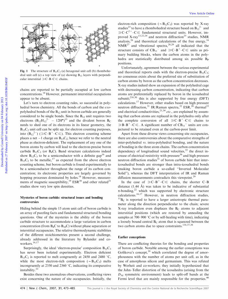
In its idealized, most symmetric form, the structure of boron
carbide is usually described in a rhombohedral unit cell (space
group R-3m) that contains one icosahedral B12 unit and one
linear yC–B–Cx chain, corresponding to the ideal composi-
tion B13C2. The B12 units are composed of crystallographically
distinct boron atoms BEq (Equatorial) and BP (Polar) in a D3d
environment. These B12 units are interconnected by carbon
atoms through their BEq atoms, forming layers, while the B12
units of the adjacent layers are linked through interpolyhedral
BP–BP bonds. Besides these two kinds of boron atoms in the
icosahedron, there is a unique boron (BC) that connects the
two carbon atoms of the adjacent layers, forming the short
linear yC–B–Cx chain. Fig. 1 depicts the hexagonal (z = 2)
and rhombohedral (z = 1) forms of B13C2, along with a top
view of the structure.
That structure is the ideal archetype, but boron carbide
actually exists over a widely varying compositional range
B12+xC3�x (0.06 o x o 1.7).12 Owing to the similarity of
boron and carbon in electron density and nuclear cross-section
(11B and 12C), both X-ray and neutron diffraction studies are
not very successful in unambiguously assigning the exact site
occupancies. It is generally agreed that the carbon and BP sites
(Fig. 1) exhibit mixed occupancies to varying degrees, depend-
ing on the carbon concentration.13 Besides, the three-atom
Department of Chemistry and Chemical Biology, Baker Laboratory,Cornell University, Ithaca, NY 14853, USA. E-mail:[email protected] The HTML version of this article has been enhanced with additionalcolour images.z Present address: Department of Chemistry, Pondicherry University,Pondicherry 605 014, India.
This journal is �c the Royal Society of Chemistry and the Centre National de la Recherche Scientifique 2007 New J. Chem., 2007, 31, 473–485 | 473
PAPER www.rsc.org/njc | New Journal of Chemistry
Dow
nloa
ded
by C
orne
ll U
nive
rsity
on
04 F
ebru
ary
2013
Publ
ishe
d on
27
Febr
uary
200
7 on
http
://pu
bs.r
sc.o
rg |
doi:1
0.10
39/B
6184
93F
View Article Online / Journal Homepage / Table of Contents for this issue
chains are reported to be partially occupied at low carbon
concentrations.14 However, permanent interstitial occupations
appear to be absent.
Let’s turn to electron counting rules, so successful in poly-
hedral boron chemistry. All the bonds of carbon and the exo-
polyhedral bonds of the B12 unit in boron carbide are generally
considered to be single bonds. Since the B12 unit requires two
electrons (B12H122� � 12H�)15 and the divalent boron BC
needs to shed one of its electrons in its linear geometry, the
B13C2 unit cell can be split up, for electron counting purposes,
into (B122�) (yC–B+–Cx). This electron counting scheme
places a net �1 charge on B13C2; hence we refer to the neutral
phase as electron-deficient. The replacement of any one of the
boron atoms by carbon will lead to the electron-precise boron
carbide B12C3 (or B4C). Band structure calculations indeed
show B12C3 to be a semiconductor with a definite gap16 and
B13C2 to be metallic,17 as expected from the above electron
counting scheme, but boron carbide is found experimentally to
be a semiconductor throughout the range of its carbon con-
centration; its electronic properties are largely governed by
hopping processes dominated by holes.18 However, measure-
ments of magnetic susceptibility,19 ESR20 and other related21
studies show very low spin densities.
Mysteries of boron carbide: structural issues and bonding
controversies
Hiding behind the simple 15 atom unit cell of boron carbide is
an array of puzzling facts and fundamental structural/bonding
questions. One of the mysteries is the ability of the boron
carbide structure to accommodate a large variation in carbon
concentration (from B4C to B10C) without phase separation or
interstitial occupancies. The relative thermodynamic stabilities
of the different stoichiometries present a second challenge,
already addressed in the literature by Bylander and co-
workers.16,17
Surprisingly, the ideal ‘electron-precise’ composition B12C3
has never been isolated experimentally. Electron deficient
B13C2 is reported to melt congruently at 2450 and 2480 1C,
while the most electron-rich composition (BB12C3) melts
incongruently at 2350 and 2360 1C, indicating its comparative
instability.22
Besides these two anomalous observations, conflicting views
exist concerning the nature of site occupancies. Initially, the
electron-rich composition (BB12C3) was reported by X-ray
studies23 to have a rhombohedral structure based on B122� and
yC–C2+–Cx fundamental structural units. However, im-
proved X-ray13,22,24 and neutron diffraction25 studies, NMR
analysis,26 and theoretical calculations of the free energy,16
NMR27 and vibrational spectra,28,29 all indicated that the
structure consists of CB11� and yC–B+–Cx units as pri-
mary building blocks, where the carbon atoms in the poly-
hedra are statistically distributed among six possible BP
positions.
Unfortunately, agreement between the various experimental
and theoretical reports ends with the electron-precise B12C3;
no consensus exists about the preferred site of substitution of
carbon atoms by boron as the carbon concentration decreases.
X-ray studies indeed show an expansion of the polyhedral cage
with decreasing carbon concentration, indicating that carbon
atoms are preferentially replaced by boron in the icosahedral
subunit;25b,30 this is also supported by free energy (DFT)
calculations.17 However, other studies based on high pressure
neutron diffraction,31 IR/Raman spectra,32 ESR,20 thermal33
and electrical conductivities,21,34 etc., are explained by assum-
ing that carbon atoms are replaced in the polyhedra only after
the complete conversion of all yC–B+–Cx chains to
yB–B+–Cx. A significant number of CB11� units are con-
jectured to be retained even at the carbon-poor limit.
Apart from these diverse views concerning site occupancies,
there are also controversies about the comparative strengths of
inter-polyhedral vs. intra-polyhedral bonding, and the nature
of bonding in the three atom chains. The carbon concentration
dependency of longitudinal sound velocities,35 the direct in-
crease of electrical resistivity with pressure36 and high pressure
neutron diffraction studies31 of boron carbide hint that inter-
icosahedral bonds are stronger than intra-icosahedral bonds
(making boron carbide a so-called ‘‘Inverted Molecular
Solid’’), whereas the DFT interpretation of IR and Raman
diffusion measurements contradicts this viewpoint.29
In the case of yC–B+–Cx chains, the shorter C–B
distance (1.44 A) was taken to be indicative of substantial
p-bonding,22 which was supported by electronic structure
calculations.16,17 However, in neutron diffraction studies,11BC is reported to have a larger anisotropic thermal para-
meter along the direction perpendicular to the chain; severe
X-ray irradiation even displaces the BC atoms to adjacent
interstitial positions (which are restored by annealing the
samples at 700–900 1C or by self-healing with time), indicating
a loosely bound central BC atom that is squeezed between the
two carbon atoms due to space constraints.13b,37,38
Earlier conceptions
There are conflicting theories for the bonding and properties
of boron carbide. Notable among the earlier conceptions was
Golikova’s concept,39 which correlated the degree of amor-
phousness with the number of atoms per unit cell, as in the
case of amorphous silicon and germanium. This was refuted
by Werheit and co-workers; they initially hypothesized that
the Jahn–Teller distortion of the icosahedra (arising from the
D3d symmetric environment) leads to split-off bands at the
Fermi level that are mainly responsible for the properties.40
Fig. 1 The structure of B13C2 (a) hexagonal unit cell (b) rhombohe-
dral unit cell (c) a top view of (a) showing B12 layers with perpendi-
cular interstitial yC–B–Cx chains.
474 | New J. Chem., 2007, 31, 473–485 This journal is �c the Royal Society of Chemistry and the Centre National de la Recherche Scientifique 2007
Dow
nloa
ded
by C
orne
ll U
nive
rsity
on
04 F
ebru
ary
2013
Publ
ishe
d on
27
Febr
uary
200
7 on
http
://pu
bs.r
sc.o
rg |
doi:1
0.10
39/B
6184
93F
View Article Online

However, in their recent reports, this hypothesis was taken
back on the grounds that the computed HOMO–LUMO gap
of 1.5 eV for the Jahn–Teller-distorted neutral B12H12 con-
siderably exceeds the distance between the actual valence and
the split-off band.14 Furthermore, such a split-off band, if it
exists, implies extended states, while the interpretation of
transport properties requires the localization of states. Re-
cently, the same group reported, albeit qualitatively, that the
valence electron deficiency arising from the reduction of
carbon concentration correlates with the vacancies and anti-
site defects.14
Some experimentalists endorse the bipolaron model pro-
posed by Emin38,41 for explaining electronic transport in
boron carbides. Based on the fact that the spin density of
boron carbide is two orders of magnitude lower than the
concentration of charge carriers, i.e., holes, Emin proposed
that the charge carriers are paired-up to form small spinless
bipolarons, similar to the Cooper pairs in superconducting
materials. To explain the formation of bipolarons, the model
assumes that the yC–B+–Cx chains of the ideal B12C3 are
replaced by neutral yB–B+–Cx chains upon carbon reduc-
tion until all the yC–B+–Cx chains are exhausted. This
substitution deprives the CB11 polyhedral units of their re-
quirement for additional electrons. Emin proposed that two
such neutral CB11 units may disproportionate: 2CB11 -
CB11� + CB11
+ leading to the formation of CB11+, which
is the chemical equivalent of a bipolaron. This model success-
fully explained several properties of boron carbide, but the
implications of this model on structure and bonding are
inconsistent with all the theoretical studies reported so far,
and also with several other experimental reports as well.14,40
Clearly, there are many questions (and models) around
boron carbide. We see three as fundamental: (1) Why does
boron carbide refuse to be electron-precise? (2) How does
electron deficiency-induced partial occupation of the valence
bands affect the chemical bonding in the material? (3) How are
electron deficiency and disorder in site occupancies related?
Our attempts to answer these questions also reveal how the
seemingly conflicting models proposed earlier nevertheless
selectively describe well some aspects of the nature of boron
carbide.
We have chosen the most symmetric composition B13C2 and
employed a deconstructive approach. The structure is broken
into molecular fragments and is assembled back into sub-
lattices, all along inquiring into the evolution of the molecular
orbitals of the fragments into bands of the extended structure.
Computational methodology
Geometrical optimization of the selected molecular models are
done using the Gaussian 98 suite of programs42 at the density
functional-based B3LYP/6-31G* level of theory;43 frequency
calculations characterize the nature of the stationary points.
For arriving at the equilibrium geometries of the extended
structures, we employ the DFT-based VASP program.44 This,
together with the extended Huckel45 (eH)-based YAeHMOP
suite of programs,46 is used for computing the band structures
and density of states. We employ eH COOP47 (Crystal Orbital
Overlap Population) analysis as the primary tool for exploring
the nature of bonding. In the VASP calculations, we chose
ultrasoft pseudopotentials based on the projector-augmented
wave method48 using the local density approximation,49 which
is ideal for arriving at equilibrium geometries. All these
calculations are well-converged with respect to the chosen
cut-off energy and k-point sampling (by the Monkhurst–Pack
scheme50). The energies of the MOs for the molecules (as well
as those of the fragments) used in the interaction diagrams are
derived from eH calculations.
Results and discussion
Molecular models
We start with the most symmetric B12(CBC) form (B13C2) and
construct molecular models that closely simulate the bonding
environment of the fragments in the boron carbide structure.
Fig. 2 shows the D3d symmetric bonding environment of the
B12 and yC–B–Cx units in B13C2. The upper and lower
triangles of BP atoms in the B12 unit are connected to other
distinct B12 units. The central six BEq atoms form a distorted
hexagon (resembling the chair form of cyclohexane) and are
connected to yC–B–Cx units.
Modelling the B12 environment
It has long been suspected that the varying carbon concentra-
tion of boron carbide has an electronic origin. To see how this
might happen, we analyze the nature of the MOs of B12 units,
yC–B–Cx chains and the interactions among them. For the
B12 unit, we ignore the 12 MOs formed by the outward-
pointing sp hybrids of the boron atoms, as they are mostly
involved in exo-polyhedral s-bonds and should lie, as a group,
lower in energy.51 Among the MOs formed from the rest of the
12 sp hybrids that point towards the center of the icosahedra
and the 24 tangential p-orbitals, only the 13-most bonding
MOs are filled to give B122�. They transform as ag + t1u +
hg + gu in an ideal icosahedral symmetry; these are the n + 1
(n = 12) skeletal MOs of the Wade Model.52 Of these, the
lowest ag is of pure radial character and the HOMO, gu, arises
purely from the tangential p-orbitals. The remaining t1u and hghave substantial radial-tangential mixing.53
We anticipate that the valence bands of boron carbide arise
from the HOMOs (Highest Occupied Molecular Orbitals) of
B12 units interacting either with the frontier MOs of
yC–B–Cx chains or with the adjacent B12 units. These
interactions will be predominantly of p-type because the
HOMOs of the B12 units are mainly tangential. We have
constructed two molecular models to mimic these
Fig. 2 The bonding environment of B12 units and C–B–C units in
B13C2.
This journal is �c the Royal Society of Chemistry and the Centre National de la Recherche Scientifique 2007 New J. Chem., 2007, 31, 473–485 | 475
Dow
nloa
ded
by C
orne
ll U
nive
rsity
on
04 F
ebru
ary
2013
Publ
ishe
d on
27
Febr
uary
200
7 on
http
://pu
bs.r
sc.o
rg |
doi:1
0.10
39/B
6184
93F
View Article Online

p-interactions. The first model has six fluorine atoms con-
nected to the BEq atoms, modelling –B–Cx interactions; in
the second model they are at the BP positions to mimic the B12
units. Fluorine is selected as a substituent due to its small size
and to bring into focus the p-interactions. The p-interactionwill be moderate in the model, as the p-type lone pairs of
fluorine are low in energy and quite contracted. In the real
structure, the p-interaction may be larger.
To start, we explore the nature of these p-interactionsbetween the B12 skeletal MOs (as in icosahedral B12H12
2�)
and the fluorine substituents using eH calculations. Fig. 3
shows the perturbation of the thirteen skeletal bonding orbi-
tals (filled) of icosahedral B12H122� by fluorine atoms, upon
axial and equatorial substitutions, leading to B12F6H62� iso-
mers. The energies of the MOs were obtained from eH
calculations using standard bond lengths close to those ob-
served experimentally. (B–B = 1.79, B–F = 1.39 and B–H =
1.20 A).
Due to the reduced D3d symmetry of the substituted sys-
tems, the multi-fold degeneracies of the MOs in the icosahe-
dral B12 are lost. The four-fold degenerate gu HOMO of
B12H122� (Ih) splits into a1u + a2u + eu in D3d. These MOs
will have antibonding interactions with the appropriate com-
bination of fluorine lone pairs. Their in-phase combinations lie
low in energy, and are mostly of fluorine character due to the
higher electronegativity of fluorine. However, their out-of-
phase combinations, which are predominantly concentrated
on the boron atoms of the polyhedron, are destabilized with
respect to B12H122�. Removal of electrons from this system
would result in p-bonding between the polyhedra and fluorine
atoms.
The splitting of the HOMO is the same for both isomers, as
they belong to the same point group. However, the ordering of
the levels reverses between the isomers. Since rationalization
of this MO ordering is critical in determining whether BP or
BEq are involved in partial multiple bonds in the electron-
deficient boron carbide, we look in detail at the nodal proper-
ties of the four MOs of the B122� unit in a D3d environment.
Seen along the C3 axis, they are drawn in Fig. 4.
To describe the nodal properties of these MOs, we focus
separately on the top and bottom triangle of BP atoms, and
then their interactions with the central distorted hexagonal
ring. The a2u MO is all-bonding between the BP atoms, while
the interactions between the central BEq atoms are antibond-
ing due to the distortion of the hexagon (as the side view of the
central hexagon in Fig. 4b shows). The BEq–BEq overlap in the
a2u MO is s-antibonding and p-bonding; p dominating. In the
case of a1u, the situation is reversed. This MO is antibonding
between BP atoms, but the BEq atoms are bonding with each
other. In both MOs, the interaction of the central hexagon
with the triangular BP atoms of the top and bottom is bonding;
the difference is in the nature of the interaction, i.e., a2u has
strong end-on s-overlap while a1u has p-type. The magnitude
of the AO coefficients at each atom also differs substantially,
depending on the nature of the interactions (not shown in the
Fig. 4). In a2u, the coefficients are larger for BP atoms. On the
contrary, in the a1u MO, the coefficients are large on the BEq
atoms. The doubly degenerate eu MO has mixed character-
istics of both of these MOs in different regions of the skeleton.
The size of the orbital coefficients allows us to understand
how the substitution of six fluorine atoms at equatorial and
axial positions brings about the order reversal in the splitting
of the hg set of the icosahedra. p-Interactions in fluorine
substitution at the polar positions destabilize a1u most, as this
MO has concentrated more at the BP positions; conversely,
equatorial fluorine substitution exerts maximum destabiliza-
tion on a2u.
To understand how electron deficiency affects the bonding,
we have removed two electrons from both of these fluorinated
models and optimized the neutral B12H6F6 geometries at the
B3LYP/6-31G* level of theory. The calculated bond lengths of
the two isomers are given in Fig. 5, along with the B12F122�
geometry for comparison. The B12 skeleton undergoes sub-
stantial deformation, different in nature for the isomers.
Fig. 3 The perturbation of skeletal MOs of icosahedral B12H122� by
the substitution of fluorine atoms at the equatorial and polar sites.
Fig. 4 (a) The D3d MOs derived from the HOMO (hg) of B122�
polyhedra. (b) A side view of the central hexagon fragment of the
a2u MO.
476 | New J. Chem., 2007, 31, 473–485 This journal is �c the Royal Society of Chemistry and the Centre National de la Recherche Scientifique 2007
Dow
nloa
ded
by C
orne
ll U
nive
rsity
on
04 F
ebru
ary
2013
Publ
ishe
d on
27
Febr
uary
200
7 on
http
://pu
bs.r
sc.o
rg |
doi:1
0.10
39/B
6184
93F
View Article Online

Compared to the B–B bond length of 1.79 A in the electron-
precise B12F122�, the BP–BP distances of the equatorially-
substituted neutral B12F6H6 are shortened to 1.73 A, while
in the polar isomer they are elongated to 1.99 A.
The computed LUMO of both isomers of the neutral
B12H6F6 (Fig. 6) shows the expected antibonding p-interac-tions between the B12 skeleton and the six fluorine atoms.
Partial B–F multiple bonding, delocalized over all the B–F
bonds of the skeleton, is implied. The observed B–F distance
of 1.33 A in both isomers is shorter than the singly-bonded
B–F distance (1.39 A) computed for the electron-precise
B12F122�. Since electrons are removed from a MO that is
bonding within the B12 skeleton, the strengthening of the exo-
B–F bonds also results in a weakening of the polyhedral B–B
bonding.
Frequency calculations characterize both of these B12F6H6
isomers as stationary points on their potential energy surface;
so perhaps these molecules can be made. Substitution of
chlorine atoms in place of fluorine atoms also gives similar
results.
The ability of B12 units to engage in exo-polyhedral multiple
bonding has been suggested in recent work.54–57 In our earlier
theoretical studies on polyhedral boranes, we have shown that
the polyhedral cages can shed two or more electrons, even with
two electronegative substituents such as O, N–H, S, etc.56
Further evidence for their easy oxidation comes from experi-
mental studies on persubstituted systems.54,57 Hawthorne et al.
have shown that B12(OCH2Ph)122� readily loses its extra two
electrons, and the symmetry of the B12 cage is lowered from Ihto D3d due to Jahn–Teller distortion,54 similar to the geometry
of the equatorial B12F6H6 isomer.
Returning to the consequences for the boron carbide pro-
blem, the results from the two molecular models indicate that
electron deficiency in boron carbide (due to the decrease in
carbon concentration) may lead to exohedral p-bonding be-
tween adjacent B12 units at the BP sites, or between the B12 unit
and theyC–B–Cx chains at the BEq sites. This would lead to
strong exo-polyhedral bonds at the expense of polyhedral
bonding. These B12F6H6 isomers might serve as realistic
chemical models of bipolarons, formed by the exo-multiple
bonded B12 units in boron carbide, models that perhaps are
chemically more meaningful than the controversial CB11+
polyhedra predicted earlier.38 In the next section, we inquire
how electron deficiency affects the nature of bonding in the
three-atom chains.
Modelling the CBC environment
As described earlier, each carbon atom of the linear
yC–B+–Cx chain is surrounded by three B12 units in a
staggered orientation, forming a D3d symmetric environment.
To retain the important nonbonding p-interactions between
the B12 units and the C–B–C chains, we now model the B12
units by fluorine atoms. This leads us to a F3C–B+–CF3
molecular model.
The MOs of D3d F3C–B+–CF3 can be constructed in a
number of ways, either from the interaction of CB+C units
and 6 F atoms or from two CF3 radicals and a B+. The latter
approach is more informative and is shown in Fig. 7.
The C–B distances are kept at 1.44 A (as observed in the
experimental B13C2 structure) and the C–F distances are kept
at a standard 1.30 A. The two HOMOs of F3C–B+–CF3 are
of a1g and a2u symmetry, and are C–B bonding but B–F
Fig. 7 The interaction diagram between the two CF3 fragments (left)
with the central boron cation (B+, right), resulting in the C–B
s-bonding.
Fig. 5 DFT-optimized geometries of fluorine-substituted isomers.
Fig. 6 The LUMO of equatorial and polar isomers of the neutral
B12F6H6 obtained from DFT calculations.
This journal is �c the Royal Society of Chemistry and the Centre National de la Recherche Scientifique 2007 New J. Chem., 2007, 31, 473–485 | 477
Dow
nloa
ded
by C
orne
ll U
nive
rsity
on
04 F
ebru
ary
2013
Publ
ishe
d on
27
Febr
uary
200
7 on
http
://pu
bs.r
sc.o
rg |
doi:1
0.10
39/B
6184
93F
View Article Online

p-antibonding, with some B–F s-bonding as well. Electron
deficiency will result in the removal of electrons from the a2uMO; as a result, the C–B s-bonds will be weakened, but therewill be slight p-bonding between the carbon and fluorine
atoms.
The computed Mulliken overlap population (OP) value in
BC2F6+ is 0.77 for C–B and 0.51 for C–F bonds by eH
calculations. After the removal of two electrons (BC2F63+),
the OP changes to 0.42 for the C–B bonds and 0.56 for the
C–F bonds. The effects seen are those expected.
Fig. 8 shows the optimized geometry of the F3C–B+–CF3
molecule at a B3LYP/6-31G* level of theory, along with the
shape of the a2u HOMO. The computed C–B distance of
1.59 A is longer than the C–B bond length of 1.44 A observed
in boron carbide. Assuming that the elongation of C–B bonds
in our model is due to pronounced destabilizing p-interactionsfrom the fluorine atoms, we replaced the fluorine atoms by
hydrogens, where such interactions are completely absent. The
optimized geometry of H3C–B+–CH3 has a C–B distance of
1.48 A, still somewhat longer than the observed 1.44 A in
boron carbide.
Frequency calculations indicate that F3C–B+–CF3 is a
minimum on the potential energy surface. However, the
geometry optimization of this molecule after removing two
more electrons fails to converge; both CF3 fragments are
completely detached from the central boron atom.
It is clear that electron deficiency lengthens the C–B–C
chain. It has been suggested that the 1.44 A C–B distance in
boron carbide is shortened as a consequence of ‘‘squeezing’’ of
the C–B+–C chain by the constraints of its bonding to
the B12 icosahedra.38 The observed flattening of the carbon
tetrahedra (bond angles BEq–C–BEq = 1171 and BC–C–BEq =
991) in the experimental structure of boron carbide also
supports this viewpoint.13 However, such ‘‘squeezing’’ of
single bonds is rare elsewhere in chemistry58 and we are
loathed to accept it here. It is possible that the short BC–C
distance is a result of crystallographic disorder of the type
indicated schematically in Fig. 9 below. Since there are six
such crystallographically-equivalent positions in the local
D3d symmetry of the CBC chain, this disorder may be the
cause of the large thermal ellipsoids observed in the diffraction
studies.13
In one X-ray structural study of a boron-rich boron carbide,
it was reported that a quarter of the C–B–C chains were
replaced by a B4 ring incorporating two of the six B atoms
in Fig. 9, together with the two C atoms, replaced by B.37b
To bend CF3–B+–CF3 from 1801 to 1501 takes only 7.5
kcal mol�1.
In the next section we investigate the nature of the inter-
actions between the various fragments in boron carbide by eH
calculations.
Fitting the fragments together: conflicting conclusions
So far, our MO analysis, using B12F6H6 isomers as models,
indicates that electron deficiency in boron carbide may lead to
exo-polyhedral multiple bonding, either between two adjacent
B12 units or between B12 units and CBC chains. Our
F3C–B+–CF3 model implied that exo-polyhedral multiple
bonding is likely between B12 and CBC units. Combining
these two results, it seems likely that such partial multiple
bonding is at work between B12 and CBC units. What would
be needed is for the HOMOs of these two fragments to interact
and the electrons to be removed from the resulting antibond-
ing combination. But do these fragment frontier MOs have
appropriate symmetry to interact?
To answer this question, we use another simple molecular
model, one which simulates the interaction between the
C–B–C chains and the B12 units. Fig. 10 depicts the bonding
environment around the carbon atom, which is the nerve
center for the formation of exo-polyhedral multiple bonds.
The simplest model of this environment is HC(BH)3, where the
–B12 units are replaced by [–B–H] groups and where
yC–B+–Cx is replaced by a C–H bond. Since the a1u and
a2u frontier MOs of the B12 units are filled, tangential
p-orbitals, modelling of the B12 units requires charged
[–B–H]3� groups, where the two unhybridized p-orbitals of
the boron atom are filled. Therefore, the net charge of the
model molecule will be HC(BH)39�.
We need, thus, the orbitals of HC(BH)39�, which may be
constructed from CH and [BH]39�. For the [BH]3
9� fragment,
the MOs arising from the three inward-pointing sp hybrids
and two sets of tangential p-orbitals form nine MOs, drawn
schematically in Fig. 11. The MOs constructed from the
tangential (Fig. 11a) and p-type (Fig. 11b) p-orbitals simulate
the two different frontier MOs, a1u and a2u, of the B12 unit,
respectively, and have to be filled. The three radial MOs then
contain the three electrons left (Fig. 11c), and are set up to
form the C–B s-bonds upon interaction with the C–H unit.
From our knowledge of main group overlapping, we reason
that the splitting of energy levels will be most pronounced in
the radial set, followed by the tangential orbitals, while the
p-set should have the smallest splitting in the group.
The interaction between this [–B–H]39� fragment and the
C–H group in a C3v environment is illustrated in Fig. 12. The
C–B bond lengths are kept at 1.60 A, as reported in the X-ray
structure of B13C2. All the MOs shown in the diagram for
HC(BH)39� are filled. The HOMO of this molecule, a2,
Fig. 9 A disorder that is possibly responsible for the short B–C
distance in the C–B–C unit. The displacement has been exaggerated
for clarity.
Fig. 8 The DFT-optimized geometry of BC2F6+ and its HOMO.
478 | New J. Chem., 2007, 31, 473–485 This journal is �c the Royal Society of Chemistry and the Centre National de la Recherche Scientifique 2007
Dow
nloa
ded
by C
orne
ll U
nive
rsity
on
04 F
ebru
ary
2013
Publ
ishe
d on
27
Febr
uary
200
7 on
http
://pu
bs.r
sc.o
rg |
doi:1
0.10
39/B
6184
93F
View Article Online

corresponds to the most antibonding combination of in-plane
tangential p-orbitals of the three boron atoms. None of the
MOs of the C–H fragment has a2 symmetry; hence, this MO
remains nonbonding. This implies that removal of electrons
from this MO will not lead to exo-polyhedral multiple bond-
ing. Despite it having no interactions with the central C–H
group, this MO is the HOMO of the molecule, indicating that
the antibonding interactions between non-bonded boron
atoms are not insignificant, even when they are separated by
2.70 A. The overlap of one tangential p-orbital with the other
two at this distance is computed to be 0.19 by eH calculations.
Note that the a2 MO of the HC(BH)39�model simulates the
out-of-phase combination of the three a1u MOs from the B12
units around the carbon. Similarly, the a1 MO in the
HC(BH)39� model simulates the most bonding combination
of the three a2u MOs of the B12 units around the carbon. In
boron carbide, the interaction of the tangential set (Fig. 11b)
will be even more pronounced because in the a1u MO of B12
units there are bigger coefficients at BEq than in the p-typeMOs (Fig. 11a), which lead to the a2u orbitals of the poly-
hedra. Hence, it is very unlikely that the antibonding combi-
nation of a2u MOs with carbon will rise above their a1ucounterparts in the extended boron carbide structure. This
implies that if a unique ‘split-off’ valence band exists in boron
carbide (as we suggested earlier), it will be made up from a1u-
type B12 orbitals rather than a2u-type. To find out what
actually happens, we have looked at the 2D lattice.
Interactions in a 2D B12C2 lattice
We next construct a 2D model, one that has a layer of B12H6
units connected through C–H groups. As shown in Fig. 13, the
model is a hexagonal lattice that has one B12 and two HCxunits in its primitive cell. To be electron-precise, this model
requires two electrons per unit cell.
The band structure for this 2D polymer is obtained from eH
calculations, using components of the experimental geometry
of the B13C2 structure,13 and is given in Fig. 14. The colors of
the bands follow that of the B12 MOs in Fig. 3; the bands are
assigned with an assumption that, at G (Brillouin zone center,
G), the energy level pattern of the B12 unit in the extended
network is similar to that at the molecular level. The valence
band structure of B12H6(CH)22� exhibits a series of almost flat
energy bands, with little variation in energy; this is a sign of
localization. There is a band gap (B5.3 eV) at 54 electrons,
i.e., a �2 charge.
Fig. 10 The bonding environment of carbon in boron carbide and its
molecular model HC(BH)39�
.
Fig. 11 A schematic illustration of the MOs generated by (a) p (b)
tangential and (c) radial sp hybrids of a D3d [–BH]9� fragment.
Fig. 12 Interaction of MOs between the (BH)39� fragment (C3v) with
a CH group at the center. MOs of dissimilar symmetry are shown in
distinct colors.
Fig. 13 The structure of a 2D model B12H6(CH)2.
This journal is �c the Royal Society of Chemistry and the Centre National de la Recherche Scientifique 2007 New J. Chem., 2007, 31, 473–485 | 479
Dow
nloa
ded
by C
orne
ll U
nive
rsity
on
04 F
ebru
ary
2013
Publ
ishe
d on
27
Febr
uary
200
7 on
http
://pu
bs.r
sc.o
rg |
doi:1
0.10
39/B
6184
93F
View Article Online

As we outlined above, our interest is in electron-deficient
structures relative to this electron count. At the top of the
valence band is a band very slightly split-off (by B0.23 eV)
from the other bands. This band would be vacated in electron-
deficient neutral B12H10(CH)2. The COOP curves (Fig. 15)
indicate that in this band, there is intra-polyhedral BEq–BEq
bonding; there is also BP–BEq bonding and some BP–BP
antibonding. As we have seen earlier, these features—BP–BP
antibonding and BEq–BEq bonding—are characteristic of the
a1u HOMO of the B12 unit (Fig. 4 and Fig. 6). This suggests
that the top band arises from this MO.
We anticipated that this high-lying MO should be nonbond-
ing with the C–H group modelling CBC (see previous discus-
sion), as discussed above. Surprisingly, however, the COOP
curve shows the split-off band to be BEq–C bonding. This is
possibly due to mixing-in of some antibonding B12 MOs. The
implication is that the BEq–C bond will be weakened by the
removal of electrons from the electron-precise composition, in
contradiction to our expectations of BEq–C antibonding in this
band. Indeed, the BEq–C curve shows some antibonding
character, but this occurs below the Fermi level of the neutral
B12H6(CH)2. Only intrapolyhedral BP–BP bonds will be
strengthened by removing electrons from the electron-precise
compound. The COOP between the BEq atoms of the adjacent
B12 units (dotted line in Fig. 15) shows that in this region of
energy, there is significant antibonding character between
these atoms, even though they are 2.7 A apart.
We wondered if replacement of the yC–B+–Cx chains by
a simple C–H group in the model 2D polymer might be the
reason why BEq–C antibonding emerges well below the Fermi
level. Hence, we did another calculation, replacing the C–H
groups with yC–B+–CH3 groups in the model structure.
However, the valence band structure and the nature of the
COOP curves (not shown here) remain mostly unchanged.
While these models are instructive, it is clear that their
description of the bonding in boron carbide is not complete.
Bulk calculations on boron carbide
The range of carbon concentrations in boron carbide can be
ideally viewed as being between B12C3 and B14C; as many as
two carbon atoms are replaced by boron atoms (though both
extremes of this variation are not experimentally character-
ized). This amounts to a total variation of two electrons per
rhombohedral unit cell. Hence, we chose the most symmetric
B13C2 (B12CBC) composition and studied the effect on its
bonding of adding or removing one electron from the unit cell.
The addition of one electron, i.e., B13C2�1, simulates the
electron-precise B12C3 composition, while removing one elec-
tron, as in B13C2+1, simulates the carbon poor extreme of
B14C. Structural optimization of these charged unit cell mod-
els permit the studying of the electronic variation with full
preservation of lattice symmetry.
Fig. 14 The band structure of the 2D polymer B12H6(CH)2.
Fig. 15 (a) COOP curves for various bonds in B12H6(CH)2. Different types of bonds and their COOP curves are shown in distinct colors. (b) An
enlarged view of the COOP curves around the Fermi.
480 | New J. Chem., 2007, 31, 473–485 This journal is �c the Royal Society of Chemistry and the Centre National de la Recherche Scientifique 2007
Dow
nloa
ded
by C
orne
ll U
nive
rsity
on
04 F
ebru
ary
2013
Publ
ishe
d on
27
Febr
uary
200
7 on
http
://pu
bs.r
sc.o
rg |
doi:1
0.10
39/B
6184
93F
View Article Online

In our study of B13C2 with +1, 0 and �1 charges, we used a
plane-wave cut-off energy of 500 eV with a k-point separation
of about 0.027 A�1 (8 � 8 � 8 mesh). Since boron carbide is
reported to have negligible spin density over its range of
carbon substitution, we chose do to all the calculations with-
out spin polarization. The results of the geometry optimization
are given in Table 1. The optimized geometric parameters of
B13C2 are comparable to experimental reports. We did not do
a direct comparison between experimental and computed
structural parameters since, in all the experimental reports,
there is ambiguity about the carbon concentration and mixed
occupancies.
Boron carbides of varying carbon concentration (i.e., the
carbon-rich B12C3, the high symmetric B13C2 and the boron-
rich B14C) are modelled by anionic B13C21�, neutral B13C2 and
cationic B12C31+, respectively. Ideally, geometry optimization
of these model systems should reveal the strengthening and
weakening of different bonds with increasing carbon concen-
tration, i.e., weakened bonds will be elongated and strength-
ened bonds will be shortened. However, due to the difference
in total molecular charge for the same atomic composition
(B13C21+, B13C2, B13C2
1�), the unit cell expands with the
addition of more electrons, elongating all the bonds. However,
the variation in bond angles around carbon still remains a
good indicator of changes in the bonding environment. As we
move from B13C21� to B13C2
1+, the ideally sp3-hybridized
carbon tends to be sp2-hybridized. The BEq–C–BEq bond angle
increases from 116.561 in B13C21� to 118.351 in B13C2
1+,
whereas the BEq–C–Bc bond angle is reduced from 100.821
to 97.441. This clearly indicates the formation of multiple
bonding between BEq and C, and the weakening of the
s-bond between C and Bc.
To compare the bond distances, we computed (see the last
column of Table 1) an ‘‘adjusted variation’’ by adding 0.06 A
(the average effect on every bond of subtracting two electrons).
Judging by the adjusted variation, on moving from the
electron-precise B13C2�1 to the electron-deficient B13C2
+1,
the exo-polyhedral C–BEq bonds should be shortened by
0.04 A, while the C–BC bond length of the C–B–C chains
should elongate by 0.05 A, indicative of bond weakening. The
exo BP–BP bonds are also compressed by 0.01 A, though this is
not as pronounced as for BEq–C. These trends also indicate
that exo-polyhedral multiple bonding is indeed present,
formed preferentially between BEq–C rather than BP–BP.
Within the polyhedra, the maximum adjusted variation
(�0.04 A) is observed between BP–BP bonds, as in the case
of our model calculations with B12F6H6. Since the removal of
electrons leads to the shortening of this bond, this case appears
to be related to the equatorial isomer of B12F6H6—another
indication that exo-polyhedral multiple bonds are preferen-
tially formed at the equatorial sites (BEq–C). However, the
trend in the B–B bond length variations observed in our
molecular models is not exactly reflected in the extended
structure calculations. This may be due to the increased
constraints of the translational symmetry in boron carbide,
absent in the molecular models, which have more degrees of
freedom to relax their bond lengths. Or it may just be that
the bonding in boron carbide is more complex than what
is expected from the simple molecular models discussed
earlier.
We have also analyzed the Crystal Orbital Overlap Popula-
tion (COOP) curves generated from eH calculations on the
DFT-optimized structure of B13C2. The different types of
bonds in B13C2 and their COOP curves are given in Fig. 16.
Table 1 Optimized geometric parameters (distances in A, angles in 1) of boron carbide from DFT calculations
Parameter B13C2�1 B13C2 B13C2
+1 Variationa Adjusted variationb
Cell length (a) 5.26 5.13 4.99 �0.27Rhombohedral angle 65.19 66.08 67.29 +2.1a 1.77 1.75 1.70 �0.07 �0.01b 1.82 1.76 1.72 �0.10 �0.04c 1.81 1.80 1.78 �0.03 +0.03d 1.81 1.77 1.75 �0.06 0.00e 1.77 1.77 1.76 �0.01 +0.05f 1.64 1.59 1.54 �0.10 �0.04g 1.44 1.43 1.43 �0.01 +0.05BEq–C–BEq 116.56 117.3 118.35BEq–C–Bc 100.82 99.57 97.44
a For two electrons. b Variation +0.06 A. See text for explanation.
This journal is �c the Royal Society of Chemistry and the Centre National de la Recherche Scientifique 2007 New J. Chem., 2007, 31, 473–485 | 481
Dow
nloa
ded
by C
orne
ll U
nive
rsity
on
04 F
ebru
ary
2013
Publ
ishe
d on
27
Febr
uary
200
7 on
http
://pu
bs.r
sc.o
rg |
doi:1
0.10
39/B
6184
93F
View Article Online

The COOP curves for all the bonds, except C–BEq and
intrapolyhedral BP–BP bonds, are bonding throughout the
window shown, up to the Fermi level of B13C2�1. However,
near the Fermi level, unlike the case of the model 2D polymer,
the COOP curve for BEq–C shows significant antibonding
character. Hence, moving from electron-precise B13C2�1 to-
wards electron-poor B13C2+1 results in exo-polyhedral multi-
ple bonding at BEq sites, while some of the polyhedral bonds
are weakened.
The band structure of B13C2, computed from DFT calcula-
tions, is given, along with the eH bands, in Fig. 17. Calcula-
tions for the boron carbide system with one electron less or
more are identical to the eH method, and not that different
from each other by DFT. This is why we show only the
calculation for the neutral species, corresponding to the mid-
dle of the three Fermi levels shown.
While the electron-precise B13C2�1 is a semiconductor,
B13C2 and B13C2+1 are metallic, as expected. The DFT band
structures appear very similar to the bands obtained from
eH calculations, which supports the close fit of the default
eH parameters with the DFT results. Unlike the case of
the band structure of the 2D model B12H6(CH)2, there is no
split-off band at the Fermi level for the electron-deficient
B13C2+1.
Inspection of the eigenvalues at G show that only the top
two bands are truly degenerate. We believe that these two
bands arise primarily from the out-of-phase combination of
the eu MO of the B12 unit with the carbon atoms of the
surrounding C–B–C chains. Recall that this degenerate eu set
has mixed characteristics of MOs a1u and a2u of the B12 unit,
and is completely missing in our simplistic HC(BH)39� model.
This is the reason why the molecular models lead to ambig-
uous conclusions when considered separately. There is evi-
dence of exo-polyhedral multiple bonding between B12 units
and C–B–C chains elsewhere in the Brillouin zone.
Disorder and semiconductivity
Putting together all the pieces of partial information from
various molecular models of the idealized system, we can now
investigate the origins of disorder and the semiconducting
properties of samples of varying carbon concentration. The
analysis of bonding in the idealized, most symmetric, form of
boron carbide clearly shows that the deficiency of electrons is
encouraged by the antibonding character between the B12
units and C–B–C chains near the Fermi level. The higher
stability of carbon-deficient B13C2 over the electron-precise
B12C3 can be justified on this basis.
Fig. 16 COOP curves for the various bonds in boron carbide. Different bonds and their corresponding COOP curves are colored uniquely. The
interaction between the BEq atoms of adjacent B12 units is shown in dotted lines. The close-up picture around the Fermi is shown in a separate
window.
Fig. 17 The band structures of B13C2 from (a) DFT and (b) eH
calculations. Since the band structure of the charged B13C2�1 and
B13C2+1 are nearly identical, their corresponding Fermi levels are
shown as dotted lines on the same plot.
482 | New J. Chem., 2007, 31, 473–485 This journal is �c the Royal Society of Chemistry and the Centre National de la Recherche Scientifique 2007
Dow
nloa
ded
by C
orne
ll U
nive
rsity
on
04 F
ebru
ary
2013
Publ
ishe
d on
27
Febr
uary
200
7 on
http
://pu
bs.r
sc.o
rg |
doi:1
0.10
39/B
6184
93F
View Article Online

However, even at the B13C2 composition, the removal of
one electron does not completely remove the antibonding
between the B12 and C–B–C chain substructures. The COOP
curves (Fig. 16) show that a significant amount of antibonding
character between BP and C is retained. Since electrons can
only be removed by replacing carbon with boron in boron
carbide, further reduction must involve the replacement of
carbon atoms in the C–B–C chains, which is what led to the
antibonding interactions in the first place. To escape from this
internal conflict, the boron carbide structure resorts to dis-
order, particularly at the carbon sites. The replacement of
carbon atoms by boron in the C–B–C chains is also energeti-
cally unfavorable for exo-s-bonds, because of the greater
bond strength of C–B vs. B–B bonds. So, for any boron
carbide sample, partial replacement of carbon by boron atoms
leads to disorder. B/C disorder is also stabilizing for entropic
reasons. As this disorder leads to the localization of electronic
states,14 boron carbide remains a semiconductor, even when
the carbon concentration is varied significantly.
Structure and bonding in LiB13C2
LiB13C2 crystallizes in an orthorhombic unit cell with the
space group Imma, and the covalent network is isomeric to
B4C, comprising the same B12 and C–B–C units. The Li ions
occupy the voids, donating the electrons required by the
covalent network. However, the B12 unit in LiB13C2 is less
symmetric when compared to B4C as it has three distinct
boron atoms. While the six BEq atoms remain the same, the
six BP atoms form two groups—four of them, which we call
strained borons (BS), are distinct from the other two (BA). As
in B4C, BEq atoms are bonded to the C–B–C chains while BS
and BA are involved in inter-linkages with other B12 units. The
difference between BS and BA lies in that the exo-bonded B
atom makes an angle of 154.61 with the centroid (X–BS–BS),
while it is almost linear in the case of BA (X–BA–BA 176.81).
Another marked difference from B4C is in the inclination of
the C–B–C chains towards the B12 unit. While in B4C, the
BEq–C–BC angle tends to be perpendicular (99.61), in LiB13C2
it has an average value of 107.91. This is facilitated by a
bending of the BC atoms (C–Bc–C 174.81) in LiB13C2, which is
perfectly linear in B4C. Hence, the carbon atoms are closer to
sp3 hybridization, with an average angle around the B12s of
110.51 (BEq–C–BEq). The bonding environment around B12
and its extension in a 3D lattice is shown in Fig. 18.
Fig. 18(a) gives the bonding environment around B12, which
is identical to that in B4C. However the layer structure of the
B12 units can be perceived in a somewhat different way, owing
to the tilting of C–B–C bonds. Thus, as shown in Fig. 18(b),
different B12 layers are connected through the BA–BA bond,
and the bonding within the layer comes from BS, in addition to
the common C–B–C chains.
An eH-based band structure and the COOP of some
important bonds in the B/C sub lattice of LiB13C2 is given in
Fig. 19. Like in B4C, the BEq–C bond is antibonding just below
the Fermi level. A VASP calculation is done on the neutral
system with Li ions removed, which will be then isomorphic
and isoelectronic to the existing B13C2. It is found to be less
stable than B13C2 by 25.6 kcal mol�1 per formula unit.
Optimization of LiB13C2 by a negative charge instead of an
Li ion, i.e., B13C21� (isoelectronic to B13C2
1� discussed ear-
lier), dissociates the structure. Li seems to be vital in stabilizing
the B/C covalent network intact. Presumably the covalent
network in boron carbide is stronger than that of LiB13C2,
irrespective of the electronic variations.
Fig. 18 (a) The bonding environment around B12 and (b) the unit cell
of LiB13C2.
Fig. 19 The band structure and COOP curves of B/C sub lattice in LiB13C2. The COOPs of various bonds are colored differently.
This journal is �c the Royal Society of Chemistry and the Centre National de la Recherche Scientifique 2007 New J. Chem., 2007, 31, 473–485 | 483
Dow
nloa
ded
by C
orne
ll U
nive
rsity
on
04 F
ebru
ary
2013
Publ
ishe
d on
27
Febr
uary
200
7 on
http
://pu
bs.r
sc.o
rg |
doi:1
0.10
39/B
6184
93F
View Article Online

Conclusion
A detailed quantum chemical investigation of the structure
and bonding in boron carbide has been presented. In electron-
precise boron carbide (B12C3), the frontier bands are charac-
terized by significant p-antibonding interactions between the
BEq–C atoms, and also around the inter-polyhedral BEq–BEq
region. This leads to instability, for which the system tries to
compensate by decreasing the carbon concentration. Hence, in
different samples of boron carbide, the carbon concentration
varies significantly. Removal of electrons results in strong exo-
polyhedral BEq–C bonds, but also weakens the polyhedral
bonds and s-bonds of the C–B–C chains. We think that the
semiconducting behavior of boron carbide over its range of
carbon compositions is due to carbon substitutional disorder,
which in turn leads to localized states. The seemingly myster-
ious experimental observations of the properties and structure
of boron carbide can be understood and interpreted from this
viewpoint. Our calculations show that the bonding in the B/C
covalent network is stronger in boron carbide than in the
electron-precise boron carbide network that has been realized
in LiB13C2.
Acknowledgements
We are grateful to the National Science Foundation for its
support of the research at Cornell through grant CHE-
0204841.
References
1 I. J. McColm, Ceramic Hardness, Plenum Press, New York, 1990.2 R. R. Ridgway, J. Electrochem. Soc., 1934, 66, 117.3 (a) A. Lipp and K. Schwetz, Ber. Dtsch. Keram. Ges., 1975, 52,335; (b) H. Werheit, A. Leithe-Jasper, T. Tanaka, H. W. Rotterand K. A. Schwetz, J. Solid State Chem., 2004, 177, 575.
4 (a) R. Telle, in Structure and Properties of Ceramics, ed. M. V.Swain, Materials Science and Technology, vol. 11, VCH, Wein-heim, 1994, pp. 173–266; (b) R. Telle, Chem. Unserer Zeit, 1988,22, 93.
5 W. Jeintschko and R. P. R.-D. Hoffmann, in Handbook ofCeramic Materials, ed. R. Riedel, Wiley-VCH, New York,2000, pp. 3–40.
6 K. A. Schwetz and A. Lipp, Boron Carbide, Boron Nitride andMetal Borides, , in Ullmann’s Encyclopedia of Industrial Chem-istry, Verlag Chemie, Weinheim, 1985, pp. 295.
7 H. Werheit, Mater. Sci. Eng., B, 1995, 29, 228.8 S. D. Hwang, D. Byun, N. J. Janno and P. A. Dowben, Appl.Phys. Lett., 1996, 68, 1495.
9 M. Calendra, N. Vast and F. Mauri, Condensed Matter, LosAlamos National Laboratory Preprint Archive, 2003, http://xxx.lanl.gov/pdf/cond-mat/0312200.
10 D. Emin and T. L. Aselage, J. Appl. Phys., 2005, 95, 013529.11 N. Vojteer and H. Hillebrecht, Angew. Chem., Int. Ed., 2006, 45,
165.12 D. Gosset and M. Colin, J. Nucl. Mater., 1991, 183, 161.13 (a) U. Kuhlmann, H. Werheit and K. A. Schwetz, J. Alloys
Compd., 1992, 189, 249; (b) G. H. Kwei and B. Morosin, J. Phys.Chem., 1996, 100, 8031.
14 (a) R. Schmechel and H. Werheit, J. Phys.: Condens. Matter,1999, 11, 6803; (b) R. Schmechel and H. Werheit, J. Solid StateChem., 2000, 154, 61.
15 H. C. Longuet-Higgins and M. de V. Roberts, Proc. R. Soc.London, Ser. A, 1955, 230, 110.
16 D. M. Bylander, L. Kleinman and S. Lee, Phys. Rev. B: Condens.Matter, 1990, 42, 1394.
17 (a) D. M. Bylander and L. Kleinman, Phys. Rev. B: Condens.Matter, 1991, 43, 1487; (b) S. Lee, D. M. Bylander, S. W. Kim andL. Kleinman, Phys. Rev. B: Condens. Matter, 1992, 45,3248.
18 (a) L. Zuppiroli, N. Papandreou and R. Kormann, J. Appl. Phys.,1991, 70, 246; (b) C. Wood and D. Emin, Phys. Rev. B: Condens.Matter, 1984, 29, 4582.
19 L. J. Azevedo, E. L. Venturini, D. Emin and C. Wood, Phys. Rev.B: Condens. Matter, 1985, 32, 7970.
20 O. Chauvet, D. Emin, L. Forro, T. L. Aselage and L. Zuppiroli,Phys. Rev. B: Condens. Matter, 1996, 53, 14450.
21 T. L. Aselage, D. Emin, S. S. McCready and R. V. Duncan, Phys.Rev. B: Condens. Matter, 1998, 81, 2316.
22 J. L. Hoard and R. E. Hughes, in The Chemistry of Boron and ItsCompounds, ed. E. L. Muetterties, Wiley, New York, 1967, pp. 25.
23 (a) G. S. Zhadnov and N. G. Sevast’yanov, C. R. Acad. Sci.URSS, 1941, 32, 432; (b) H. K. Clark and J. L. Hoard, J. Am.Chem. Soc., 1943, 65, 2115.
24 A. C. Larsen and D. T. Cromer, Acta Crystallogr., Sect. A: Cryst.Phys., Diffr., Theor. Gen. Cryst., 1972, 28, S53.
25 (a) K. L. Walters and G. L. Green, Quarterly Status Report on theAdvanced Plutonium Fuels Program, Los Alamos Scientific La-boratory, Los Alamos, 1970, pp. 14; (b) A. Kirfel, A. Gupta andG. Will, Acta Crystallogr., Sect. B: Struct. Crystallogr. Cryst.Chem., 1979, 35, 1052.
26 T. M. Duncan, J. Am. Chem. Soc., 1984, 106, 2270.27 F. Mauri, N. Vast and C. J. Pickard, Phys. Rev. Lett., 2001, 87,
085506.28 (a) K. Shirai and S. Emura, J. Phys.: Condens. Matter, 1996, 8,
10919; (b) K. Shirai and S. Emura, J. Solid State Chem., 1997,133, 93.
29 (a) R. Lazzari, N. Vast, J. M. Besson, S. Baroni and A. DalCorso, Phys. Rev. Lett., 1999, 83, 3230; (b) N. Vast, J. M. Besson,S. Baroni and A. Dal Corso, Comput. Mater. Sci., 2000, 17, 127.
30 A. C. Larsen, in Boron Rich Solids, ed. D. Emin, T. Aslage, C. L.Beckel, I. A. Howard and C. Wood, AIP, New York, 1986,pp. 109.
31 R. J. Nelmes, J. S. Loveday, R. M. Wilson, W. G. Marchall, J. M.Besson, S. Klotz, G. Hamel, T. L. Aselage and S. Hull, Phys. Rev.Lett., 1995, 74, 2268.
32 (a) H. J. Becher and F. Thevenot, Z. Anorg. Allg. Chem., 1974,410, 274; (b) D. R. Tallant, T. L. Aselage, A. N. Campbell and D.Emin, Phys. Rev. B: Condens. Matter, 1989, 40, 5649; (c) T. L.Aselage, D. R. Tallant and D. Emin, Phys. Rev. B: Condens.Matter, 1997, 56, 3122.
33 C. Wood, D. Emin and P. E. Gray, Phys. Rev. B: Condens.Matter, 1985, 31, 6811.
34 (a) T. L. Aselage, D. Emin and S. S. McCready, Phys. StatusSolidi B, 2000, 218, 255; (b) T. L. Aselage, D. Emin and S. S.McCready, Phys. Rev. B: Condens. Matter, 2001, 64, 054302.
35 (a) D. Emin, in Physics and Chemistry of Carbides, Nitrides andBorides, ed. R. Freor, Kluwer Acadamic Publishers, The Nether-lands, 1991, pp. 691; (b) J. Gieske, T. L. Aselage and D. Emin, inBoron Rich Solids, ed. D. Emin, T. L. Aselage, A. C. Switendick,B. Morosin and C. L. Beckel, AIP, New York, 1991, pp. 376.
36 G. A. Samara, D. Emin and C. Wood, Phys. Rev. B: Condens.Matter, 1985, 32, 2315.
37 (a) C. W. Tucker, Jr and P. Senio, Acta Crystallogr., 1955, 8, 371;(b) H. L. Yakel, Acta Crystallogr., Sect. B: Struct. Crystallogr.Cryst. Chem., 1975, 31, 1797.
38 D. Emin, Phys. Rev. B: Condens. Matter, 1988, 38, 6041.39 (a) O. A. Golikova, Phys. Status Solidi A, 1979, 51, 11; (b) O. A.
Golikova, in Novel Refract. Semicond. Symp. 1987, ed. D. Emin,T. L. Aselage and C. Wood, Pittsburg, PA, 1987, vol. 97, pp. 177.
40 (a) R. Franz and H. Werheit, Europhys. Lett., 1989, 9, 145; (b) R.Franz and W. Werheit, AIP Conf. Proc., 1990, 231, 29.
41 D. Emin, Phys. Today, 1982, 35, 34.42 M. J. Frisch, G. W. Trucks, H. B. Schelegel, P. M. W. Gill, B. G.
Johnson, M. A. Robb, J. R. Cheeseman, T. Keith, G. A.Peterson, J. A. Montgomery, K. Raghavachari, M. A. Al-Laham,V. G. Zakrzewski, J. V. Oritz, J. B. Foresman, J. Cioslowsky, B.B. Stefenov, A. Nanayakkara, M. Callacombe, C. Y. Peng, P. Y.Ayala, W. Chen, M. W. Wong, J. L. Andres, E. S. Replogle, R.Gomberts, R. L. Martin, D. J. Fox, J. S. Binkley, D. J. Defrees,J. Baker, J. P. Stewart, M. Head-Gordon, C. Gonzalez and
484 | New J. Chem., 2007, 31, 473–485 This journal is �c the Royal Society of Chemistry and the Centre National de la Recherche Scientifique 2007
Dow
nloa
ded
by C
orne
ll U
nive
rsity
on
04 F
ebru
ary
2013
Publ
ishe
d on
27
Febr
uary
200
7 on
http
://pu
bs.r
sc.o
rg |
doi:1
0.10
39/B
6184
93F
View Article Online

J. A. Pople, GAUSSIAN 98 (Version 5.2), Gaussian Inc.,Pittsburg, PA, USA, 1995.
43 (a) B3LYP is Becke’s three-parameter hybrid method with a LYPcorrelation functional: A. D. Becke, J. Chem. Phys., 1993, 98,5648; (b) C. Lee, W. Yang and R. G. Parr, Phys. Rev. B: Condens.Matter, 1988, 37, 785; (c) S. H. Vosko, L. Wilk and M. Nusair,Can. J. Phys., 1980, 58, 1200; (d) P. J. Stephens, F. J. Delvin, C. F.Chabalowski and M. J. Frisch, J. Phys. Chem., 1994, 98,11623.
44 (a) G. Kresse and J. Hafner, Phys. Rev. B: Condens. Matter, 1993,47, 558; (b) G. Kresse and J. Hafner, Phys. Rev. B: Condens.Matter, 1994, 49, 14251; (c) G. Kresse and J. Hafner, Phys. Rev.B: Condens. Matter, 1996, 54, 11169.
45 R. Hoffmann, J. Chem. Phys., 1963, 39, 1397.46 G. A. Landrum and W. V. Glassy, YAeHMOP (Version 3.01).
(Freely available at http://yaehmop.sourceforge.net).47 R. Hughbanks and R. Hoffmann, J. Am. Chem. Soc., 1983, 105,
3528.48 G. Kresse and J. Hafner, Phys. Rev. B: Condens. Matter, 1999, 59,
1758.49 J. P. Perdew and Z. Zunger, Phys. Rev. B: Condens. Matter, 1981,
23, 5048.
50 H. J. Monkhurst and J. Pack, Phys. Rev. B: Solid State, 1976, 13,5188.
51 In reality there will be exo-polyhedral and polyhedral orbitalmixing to the extent symmetry allows it.
52 (a) K. Wade, Chem. Commun., 1971, 792; (b) K. Wade, Adv.Inorg. Chem. Radiochem., 1976, 18, 1.
53 M. M. Balakrishnarajan, R. Hoffmann, P. D. Pancharatna and E.D. Jemmis, Inorg. Chem., 2003, 42, 4650.
54 T. Peymann, C. B. Knobler, S. I. Khan and M. F. Hawthorne,Angew. Chem., Int. Ed., 2001, 40, 1664.
55 (a) M. L. McKee, Inorg. Chem., 2002, 41, 1299; (b) M. L. McKee,Inorg. Chem., 1999, 38, 321; (c) L. A. Boyd, W. Clegg, R. C. B.Copley, M. G. Davidson, M. A. Fox, T. G. Hibbert, J. A. K.Howard, A. Mackinnon, R. J. Peace and K. Wade,Dalton Trans.,2004, 2786.
56 (a) M. M. Balakrishnarajan and R. Hoffmann, Angew. Chem.,Int. Ed., 2003, 42, 3777; (b) M. M. Balakrishnarajan and R.Hoffmann, Inorg. Chem., 2004, 43, 27.
57 M. Baudler, K. Rockstein and W. Ochlert, Chem. Ber., 1991, 124,1149.
58 D. R. Huntley, G. Markopoulos, P. M. Donovan, L. T. Scott andR. Hoffmann, Angew. Chem., Int. Ed., 2005, 45, 7549.
This journal is �c the Royal Society of Chemistry and the Centre National de la Recherche Scientifique 2007 New J. Chem., 2007, 31, 473–485 | 485
Dow
nloa
ded
by C
orne
ll U
nive
rsity
on
04 F
ebru
ary
2013
Publ
ishe
d on
27
Febr
uary
200
7 on
http
://pu
bs.r
sc.o
rg |
doi:1
0.10
39/B
6184
93F
View Article Online


![INDEX []€¦ · BORON CARBIDE 42 BORON NITRIDE 34 BRINELL 22 BURNT REFRACTORIES 30 CALCIUM ALUMINATE 2 ... TITANIUM DIOXIDE 26 TITANIUM SLAG 39 TUNDISH SLAG 40 TUNGSTEN CARBIDE 42](https://img.dokumen.tips/doc/110x75/60670eb2f72be5794e2aa264/index-boron-carbide-42-boron-nitride-34-brinell-22-burnt-refractories-30-calcium.jpg)

![Characterization of Corrosion on Outdoor-Exposed …Numerous MMC components with continuous or discontinuous reinforcing fibers and particulates (silicon carbide [SiC], boron carbide](https://img.dokumen.tips/doc/110x75/5fda7789168d495b6511f914/characterization-of-corrosion-on-outdoor-exposed-numerous-mmc-components-with-continuous.jpg)