Embed Size (px)
Citation preview

9
ГОДИШНИК НА УНИВЕРСИТЕТА ПО АРХИТЕКТУРА, СТРОИТЕЛСТВО И ГЕОДЕЗИЯ
СОФИЯ
Том 51 2018
Брой 2
Volume Issue
ANNUAL OF THE UNIVERSITY OF ARCHITECTURE, CIVIL ENGINEERING AND GEODESY
SOFIA
Получена: 17.11.2017 г.
Приета: 04.12.2017 г.
STRUCTURAL STRENGTH EVALUATION BY NON-DESTRUCTIVE
TESTS OF RC SLAB STRUCTURE AND ANALYSIS OF
THE FAILURE CAUSES OF CONCRETE ROOF SLABS
I. Markov1, M. Al Zuhaili
2
Keywords: concrete structures, field tests, load tests, core test, in situ tests, concrete
slabs
ABSTRACT
The main objective of this paper is to evaluate the safety and serviceability of an
existing structural system by Structural Strength Evaluation by Non-Destructive Tests for
Reinforced concrete (RC) Slabs Structure, and Analysis of the failure causes of (RC) roof
slabs.
In this paper, three cases are studied on roof slabs (two-way slab, one-way joist slab
system) of three villas in Kuwait.These villas were built in 2017, 2007 and 1997, respectively.
Weakness in the strength of the concrete and the deflection in the roofs is observed, as
well as appearance of cracks in some of the slabs and in some of the beams.
The tests (load test, core test) are carried out according to ACI-318 so as to make known
that they match the strength of the existing concrete and if it is safe or not.
In the end of the paper the tests gave good results to assess the safety of the structure.
Two main reasons for the failure of two slabs are found, the first is poor implementation by the
contracting company and non-compliance with the required technical specifications, and the
second reason is fault in the design and weakness in the supervision executed by the
engineering consulting.
1 Ivan Markov, Prof. Dr. Eng., Head of Dept. “Structural Mechanics”, UACEG, 1 H. Smirnenski Blvd.,
Sofia 1046, e-mail: [email protected] 2 Mohammad Al Zuhaili, PhD student, Dept. “Structural Mechanics”, UACEG, 1 H. Smirnenski Blvd.,
Sofia 1046, e-mail: [email protected]

10
1. Introduction
The need to improve the ability of an existing building to withstand external loads arises
usually from the evidence of damage and poor behavior during a finishing period or after.
It can be known also from calculations or by test or other methods what is the bearing of
buildings for additional load that have been damaged in other places.
The method of repair and strengthening would naturally depend very largely on the
actual forces in the building as well as the structural scheme and materials used for the
construction of the building in the first instance, the technology that is visible to adopt quickly
and on the amount of funds that can be assigned to the task, usually very limited.
Some methods like splints and bandages, wire mesh with gunite, epoxy injection, etc.,
have already been tried and applied in a few countries for repairing as well as strengthening
damaged buildings. For that it is very important to evaluate the exact bearing strength for each
structural member by Non-Destructive Tests, which is relevant for a variety of reasons like the
poor implementation by the Contracting Company and non-compliance with the required
technical specifications, as well as fault in design and weakness in supervision by the
Engineering Consulting Office.
This paper describes an on-site evaluation of several roof slabs in three villas, the first
of which is one-way joist slab and the second and third are two-way solid slabs, in order to
introduce the principles and results of the method of load testing in the context of potential
projects. These case studies represent an ideal test.
The first structure has weakness and deflection equal to 7.00 cm in the mid span of slab
(12.00*10.50 m) which happened after the removal of the scaffold before carrying any load
(finish and live load), whereas the second and third structures present deflection in the center
of slabs and diffuse cracks in the top and bottom surface of slabs and beams (6.00*5.00 m) and
another slabs dimensions (6.90*5.25 m, 6.00*6.20 m).
This paper focuses on determining the load level for each structure and finding out the
causes of the failure. Special considerations are related to the design and the implementation of
the conduct of this type of load test and core test is presented and discussed. Also, its focus is
on the evaluation criteria and their significance, limitations and applicability.
2. Literature Review
Load testing of concrete structures in the United States is a century old tradition with
one of the earliest well-documented cases found in the 1890s Birkmire 1894 [1].
The American Concrete Institute began formalizing load test procedures for concrete
structures in 1920 [2] ACI 1920 [3]. At that time, the evaluation criteria for passing the load
test focused on maximum deflection under sustained load combined with the recovery of
deflection after the test load was removed. Subsequent Codes ACI 1936 defined the deflection
evaluation criterion as a function of the span length squared and divided by the total depth of
the member cross section [1]. This form of the deflection criterion is still in effect ACI 2005.
Notable investigations into load testing of concrete structures documenting the practice of the
last decades can be found in the literature of Fitz Simons and Longinow 1975, RILEM 1984,
Bungey 1989 [1, 4 – 7].
The load test method is a relatively recent development and therefore only a limited
number of reported case studies exist: Gold and Nanni 1998, Nanni and Gold 1998a,b,
Mettemeyer and Nanni 1999, Galati et al. 2004, Casadei et al. 2005 [8, 9].

11
This method attempts to make use of advances in technology e.g. equipment,
instrumentation and analytical tools to provide a safe and reliable procedure for structural
evaluation consistent with contemporary construction and engineering practices and social
needs.
3. Objectives of the Paper
The objectives of this paper are:
To evaluate the structural efficiency of the building;
To do development of in-situ evaluation methods for RC structures;
To reach the real failure causes of the roof slabs and other structural elements;
To verify the appropriate treatment work for the existing cracks and deflection;
To collect the data that is necessary to perform the researches in the future;
To provide analysis of the experimental results to professionals with evidence of
the validity of in-situ assessment;
To know the effect development of construction technology over a two-decade
period in the building materials and methods of construction.
4. First Case: Villa in Mishref Suburb in 2017
4.1. Description of the Building
The first case was built in Kuwait city in 2016 (Fig. 1, 2, 3) on an area of 400 m2 of
land, consisting of four floors: basement, ground, first and second. The building was built of
Reinforced concrete (RC). The structural system consists of columns and beams and slabs.
There are two types of roof slabs used in the building, the first one is solid slabs and the
second is one-way joist slab. That is usually used for wide spaces such as halls that are
performed without columns in the middle of it. In this case we will focus on two slabs of the
building that have clear crack and deflection problems; the first and second floor roofs are a
one-way joist slab system RC concrete.
4.2. Preliminary Investigations
The following summarizes the preliminary assessment of the structure and the sources
for the information used in designing the load tests.
4.2.1. Structural Geometry and Material Characteristics
The structural geometry including columns locations and members sizes was
determined from the engineering drawings attached, the slabs of the roof are two types, as we
mentioned before. The second type of the slabs is one-way joist slab, the Dim. of the slab is (12.00*10.50*0.50 m) (length x width x thickness) and the section of design rib is shown in
Fig. 2.
The material characteristics were provided by consulting the design office. The
specifications indicated a compressive strength of concrete of 300 kg/cm2, and minimum yield
strength for the mild reinforcement of the steel is 4000 kg/cm2.

12
4.2.2. Initial Observation and Visual Inspection
A visual inspection was carried out to inspect the condition of the existing building
structural elements, and then if needed to identify the method of loading and the slab to be
loaded.
Figure 1. First and Second Floor Roof Slabs plan Figure 2. Rib Section R1(As Designed)
Figure 3. Elevation of building
From the visual inspection, clear cracks were found on the first and second roof slabs of
the building. However, no significant cracks were found on other structural members.
At the roof of the basement and the ground floor there was no notice of a deflection of the
slab or what is alleged to worry; on the contrary, in the roof slabs of the first and second floors
deflection was apparent with the naked eye in the joist and edge beam and when measured was
about 6 – 7 cm in the middle of the span. Also, cracks appeared in the joists and beam in
addition to the vibration of the slab, therefore it was important to check the safety of the
construction of the roof, which required carrying loading test for both slabs (Fig. 4) (One-way
joist system with a 12.00 m length, 0.50 m thickness, static load test).
One way joist slab
Dim. (12.00*10.50*0.50 m)

13
4.3. Description of the Load Test
4.3.1 Load Test Configurations
The load tests were performed in a down load method; in particular, by distributing the
load of the concrete blocks on the whole area of the slab in uniform manner with known
weight to check the reaction on the slab.
Figure 4. Slab and edge beam with 6 – 7 cm deflection in the middle of the span
4.3.2. Deflection Measurement
Deflection measurement was taken in 5 different locations for by installing dial
gauges, so a significant portion of the floor was monitored during the load test. Deflection
measurements were taken with part from 100 of millimeter mounted on tripods on the level
below the slab being tested. The five dial gauges were installed at the points G1 to G5 and the
dial gauge no.1 (G1) is located at the middle of the slab as shown in Fig. 5.
Figure 5. Location of Dial Gauges and crack of F.F.S
Frist Floor Roof
slab
Edge Beam
Exist Deflection
Edge Beam Cracks
One way joist
slab
(12.00*10.50*0.50 m)

14
4.3.3. Simulation of Distributed Loading
The design loads were simulated by means of concrete blocks (30*20*15 cm) (length x
width x height) and the sample weight equal to 15 kg for each block was relatively easy to
install and control for the structure under investigation. For this purpose, this load is exactly
similar to the finish and live load because it is uniformly distributed on the whole area of the
slab equality.
The concrete blocks are distributed exactly like real load, the effects of the design load
are similar to the load test. This gives the very good response of the slab system and allows
using lighter equipment with low cost. The load test of the slabs was done in phases.
4.4. Testing Procedure
The next section shows the conceptual steps followed in order to:
determine the value of the total test load magnitude during a preparatory phase;
obtain the continuous structural assessment during the load test performance;
and,
obtain the real-time calibration of the test load according to the continuous
assessment of the boundary conditions through the measurement of selected
structural parameters.
4.4.1. Load Test Protocols
From the American Concrete Institute (ACI) standard, two variables are considered for
the principle evaluation and they are:
1) Dead load effect such as weight of slab and finish load;
2) Live load effect.
By this way, the total load (weight) that is applied on the tested deck slab can be
calculated as suggested by ACI- 318/318R [11, 12].
4.4.2. Load Calculation
Following the Building Code Requirements for Structural Concrete ACI 318/318 [12]
The Value test load shall be calculated.
Total Load = 0.85*(1.4*Dead load + 1.7*Live load)
Test load
0.85*(1.4 1.7 )W DL LL (1)
D.L i . e . Dead load Contain 1. Finishes. + 2. Services and ceiling
L.L i.e. Live Load expected.
D. L. Calculation, Finishes Floor Layers (tile2.5cm + mortar2.5cm +fill 12cm)
Tile 2.5cm U.W.=2.2T/m3) Mortar 2.5cm (U.W. =2.2 T/m Fill 12cm Th. (U.W.=1.7T/m
3)
*For Two Slabs First and Second Floor Roof:
1- Finishes Floor (tile2.5cm + mortar2.5cm +fill 12cm)
= 0.025*2200+0.025*2200+.10*1700 = 0.280 Ton/m2
2- Services and ceiling = 0.050 +0.50 = 0.100 Ton/m2
Total dead load = 0.280 + 0.100 = 0.380 Ton/m2
Live Load = 0.2 x 1= 0.200 Ton/m2
Total Test load W = 0.85*(1.4*0.380 + 1.7*0.200) = 0.740 Ton/m2

15
4.4.3. Load Configuration
The load was applied to the slab uniformly distributed on the whole area. The intensity
of the applied load as it was determined in three layers of blocks, and the total load of these
three layers equals the exactly calculated test load so the same effect in terms of negative
moment resulting from the factored, uniformly-distributed load
One square meter contains 16.5 block *15 kg = 247 kg/m2/layer.
Three layers 3*247 kg/m2= 741 kg/m
2 # 0.740 Ton/m
2.
The ACI requirements and standards for the structural using condition must be
considered and limited by two variables that are [10, 11, 12]:
1) Maximum Deflection and
2) Rebound Deflection or Residual Deflection.
According to ACI 318/318R, the maximum deflection and the rebound deflection are
2
max / 20000L h
(2)
max
/ 4rwbound
, (3)
where: Δmax is the Maximum Deflection;
Δ rebound is the Rebound Deflection or Residual Deflection;
L is length of slab on the short side, and h is thickness of slab.
4.4.4. Load Testing Procedure
Procedure for load testing
1. Install the dial gauges no.1 to 5 (G1 – G5) onto the slab structure for five points
that are located as shown in Fig. 5 and the dial gage no.3 (G1) is installed at the
middle of the slab. The dial gage installation uses the magnetic base (Fig. 6).
2. Record all initial deflections and the temperature prior to the testing.
3. Increase the load (Concrete Block Weight) step by step from 0%, 25%, 50%,
75%, and 100% of the maximum test load and each load step is held for 1 hour
(for this deck slab structure, the design maximum live load equals 200 kg/m2).
4. Except the maximum test load (100%) that has to maintain 24 hours.
5. After 24 hours, the test load is decreased step by step from 0%, 50%, 75% and
100% of the maximum test and each released load step is held for 1 hour.
6. After releasing all test loads, it is maintained for 24 hours.

16
5. First Floor Roof Slab
Figure 6. Dial Gauges Installation in F.F.S and Magnetic Holder
5.1. Calculation of Maximum Allowable Deflection:
Slab Dimension = 12.0 m x 10.5 m x 0.5 m (thickness)
Criteria I: Max Allowable Deflection: According to ACI 318
Note: Slab Span = 10.50 m, Thickness = 0.50 m
∆max = L2 / (20000*h) = (10500)2 / (2000*500) =11.025 mm. (2)
Maximum Measured Deflection ∆meas. = 20.66 mm.
∆meas. = 20.66 mm < ∆max = 11.025 mm.
Criteria II: Rebound Recovery Allowable Deflection: ∆r max ≤ ∆ max/4 Acc. to ACI 318.
5.2. Testing Results
The results from the load test are shown by tables and charts as in Table 1 respectively.
Table 1. Dial Gauges Readings
Dial Gauge Reading (mm) G1 G2 G3 G4 G5
1 Load 0% 4.5 1.16 5.84 2.59 6.07
2 Load 25% (Stage 1) 7.5 3.32 10.5 6.3 8.24
3 Load 50% (Stage 2) 13.85 5.31 17.5 12.9 15.36
4 Load 75% (Stage 3) 24.22 9.3 26.5 21.5 24.48
5 Max. Measurement dif. 19.72 8.14 20.66 18.91 18.41
During the 3rd stage of loading the excessive deflection was measured, cracks appeared in
the slab and edge beam, it became wider for that we stopped the increase of the load (Fig. 7)
Dial Gauge Reading (mm) Gr1 Gr2 Gr3 Gr4 Gr5
1 Released Load 0% 24.22 9.3 26.5 22 24.48
2 Released Load 25% 17.37 6.61 19.75 14 19.11
3 Released Load 50% 13.74 5 15.24 10 15.89
4 Released Load 75% 9.7 2.85 10.35 6 11.6
Net Deflection after Released Load 14.52 6.45 16.15 16 12.88
Dial Gauge Recovery Reading % 74% 79% 78% 82% 70%

17
Table 2. Testing Deflection (Δmax and Δrebound) and
Allowable Rebound Deflections
Dial Gauge No. ∆max ∆rmax ∆max/4 Result
G1 19.72 5.20 4.93 Unverified
G2 8.14 1.69 2.04 Verified
G3 20.66 4.51 5.165 Verified
G4 18.91 3.38 4.73 Verified
G5 18.41 5.53 4.60 Unverified
Refering to tables 1 and 2, it is clear that gauges no.G1 and G5 are unverified
Note: 1. All maximum deflections (Δmax) from the testing must be less than the
calculated deflection that equals to 11.025 mm.
2. The rebound deflections must be less than the calculated rebound deflections that
are shown in the last column of Table 2.
Figure 7. Cracks at the edge beam and F.F.S
5.3. Analysis of Load Test Results
The graph in Fig. 8 shows the relationships between the maximum deflection of the
slab deflection for the dial gauge No.1 (G1) is 19.72 mm and the rebound deflection is
5.20 mm. For the dial gauge No.5 (G5), the maximum slab deflection is 18.41 mm and the
rebound deflection is 5.35 mm. From the load test results, all maximum deflections (Δmax)
from the testing must be less than the calculated deflection that is 11.025 mm (calculated from
Equation (2)) and the rebound deflections must be less than the calculated rebound deflections
that are shown in the last column of Table 2 as well.
This slab has been suggested for demolition because the maximum deflection is more
than the allowable as per equation (2) (11.025 mm) and also before applying all of the load as
well as many cracks have appeared.
i
n
Beam
C
ccBE
AM
Crack in Beam
in
Beam
CccB
EAM
Crack in Beam Crack in
Beam
i
n
B
e
a
m
C
c
c
B
E
A
M
in
Bea
m
CccB
EAM
Crack in Slab
in
Beam
CccB
EAM
Crack in Slab in
B
e
a
m
C
c
c
B
E
A
M

18
Figure 8. Relationships between Defl.(G), Rebound Defl.(Gr) and Max. Load Percent G1-G5
“Structural member tested (First Floor Roof Slab) does not satisfy Criteria I or Criteria II”
6. Second Floor Roof Slab:
Fig. 9 is showing the location of the Dial Gauges on the plan of the second floor slab.
Figure 9. Location of the Dial Gauges on the plan of SFR
6.1. Load Calculation
In this case the same procedures: test load in the first floor roof slab (4.3), (4.4):
Total Test load W = 0.740 Ton/m2
Three layers 3*247 kg / m2= 741 kg/ m
2 # 0.740 Ton/m
2
6.2. Calculation of Maximum Allowable Deflection
Same of (5.1): ∆max= L2 / (20000*h) = (10500)
2 / (2000*500) = 11.025 mm
Maximum Measured Deflection ∆meas. = 20.66 mm.
∆meas. = 20.66 mm < ∆max = 11.025 mm
Def
lect
ion
(m
m)

19
6.3. Testing Results
A) Maximum Allowable Deflection: The results from the testing (both the maximum
and rebound deflections) must be compared with the allowable maximum and rebound
deflections that are calculate from Equation (2) and (3), respectively, as shown in Table 3.
Table 3. Dial Gauges Readings
Dial Gauge Reading (mm) G1 G2 G3 G4 G5
1 LLoad 0% 4.25 7.92 8.43 8.02 0.44
2 Load 25% (Stage 1) 10.82 17.61 18.4 11.45 3.02
3 Load 50% (Stage 2) 17.3 25.4 25.94 15.04 5.78
4 Load 75% (Stage 3) 20.81 29.71 29.91 17.86 6.26
5 Load 100% (Stage 4) 20.81 30.00 30.55 18.31 6.53
6 Max. Measurement difl. 16.56 22.08 22.12 10.29 6.09
Result Unverified Unverified Unverified Verified Verified
Table 4. Testing Deflection (Δmax and Δ
rebound) and Allowable Rebound Defl.
Dial Gauge Reading (mm) Gr1 Gr2 Gr3 Gr4 Gr5
1 Load 100% held for 24 hours 20.81 30 30.55
No
Nee
d
No
Nee
d
2 Released Load 25% 17 25.5 25.9
3 Released Load 50% 14.5 21.4 22.8
4 Released Load 75% 12 18 20
5 Released Load 100% held for 24h 10.44 16.75 17.62
Net Deflection after Released Load 10.36 13.25 12.93
Dial Gauge Recovery Reading% 63% 60% 58%
B) Rebound Recovery Allowable Deflection:
Refering to Tables 4 and 5 it is clear that gauges No. G1 – G3 are unverified.
Table 5. Testing Deflection (Δmax and Δrebound) and Allowable Rebound Deflections ACI
Dial Gauge No. ∆max ∆rmax ∆max/4 Result
G1 16.56 6.19 4.14 Unverified
G2 22.08 8.83 5.52 Unverified
G3 22.12 9.19 5.53 Unverified
G4 No need because it is verified from the first criteria (A)
G5 No need because it is verified from the first criteria(A)

20
0
10
20
30
40
0 % 2 5 % 5 0 % 7 5 % 1 0 0 %
G1 G2 G3 Gr1 Gr2 Gr3
Figure 10. Relationship between Defl. (G), Rebound Defl. (Gr) and Max. Load Percentage
6.4. Analysis of Load Test Results
The graph in Fig. 10 shows the relationships between the maximum deflection of the
slab, the dial gauges No.1 and 3 (G1, G3), which is 16.56 – 22 mm, and the rebound deflection,
which is 6.19 – 9.19 mm. But there is no need for G4 and G5 to check the rebound deflection
because it is verified from the first criteria.
From the load test results, all maximum deflections (Δmax ) from the testing must be
less than the calculated deflection that is 11.025 mm (calculated from Equation (2)) and the
rebound deflections must be less than the calculated rebound deflections that are shown in the
last column of Table 4 as well. This slab has been suggested for demolition because the
maximum deflections are more than allowable as per equation 2 (11.025 mm) and the rebound
deflections still exist in the slab structure as shown in Table 4.
7. Cutting, Demolition and Removal of Slabs
After the experimental results that appeared in the load test the slabs were unsafe,
according to the first and second procedures of the ACI-318, so the Engineering Consulting
Office decided to demolish and remove both slabs, roof I and roof II.
The demolition and removal work was carried out. The slabs and adjacent concrete
slabs were supported to ensure that the adjacent construction elements were not affected by the
cracking and demolition process.
A plan has been made to cut the concrete of the slab, taking into account the distance of
the surrounding slab, to remove it calmly and carefully, and to maintain the existing reinforcing
steel to bond with the new reinforcement steel length of 1.30 meters as shown in Fig. 11.
Upon completion of the demolition and removal, important things were found out:
* The total thickness of the executed slab ranges from 43 to 45 cm.
* The thickness of the slab is variable of the slab and varies from one place to
other.
* The thickness of the concrete slab above the ribs ranges from 8 to 12 cm.
* The reinforcement is complying with the design which is 6 # 16 per rib.
* Concrete is weak in some places and positions of the slab.
* Distribution of ribs, molds, and interstitial spaces between ribs is irregular and
unequal.
Def
lect
ion
(mm
)

21
Figure 11. Reinforced concrete slabs after cutting
8. Design Checking
Reference to the ACI 318-05 codes for the design of the one-way joist slab system of
the rib in one direction shows that the thickness limits for this type of slabs is not less than
L / 16 i.e. for the case study the required thickness is equal to 1200/16 = 75 cm at least and thus
the design is not identical to the ACI 318-05 codes (Tab. 6).
Figure 12. Table 6. Min. thickness of the rib (R1)
Measuring of thickness of
the rib (R1) slab
9. Verification of implementation
The measurement of thickness of concrete slabs after cutting showed it is 43 cm (Fig. 12)
less than the thickness required as according to ACI 318, which equals L/16 = 75 cm (Tab. 6).
Moreover, it does not match the thickness of the original design which is done by
consulting the engineering office and is equal to 50 cm. Also, the thickness of the concrete slab
above the ribs does not correspond to the thickness of the design, which is 15 cm as shown in
Fig. 2, 12. Furthermore, poor implementation can be seen in the removal of the scaffold before
the specified time or not tying the supporting stent to it. In addition, the summer temperature
increase generates cracks in the upper slab resulting from shrinking and creep [7].
10. Study and Analysis
From the mentioned above, it is found out:

22
1) Weakness of structural design carried out by the Engineering Consulting Office
in terms of the dimensions of the rib section that does not comply with the ACI-
318 requirements.
2) Defect in the implementation as the rib section of the performance and its
dimensions does not match the rib design section.
3) Bad distribution of ribs and empty molds as well as unequal distance between
them.
4) Change in the thickness of the slab from one place to another.
5) Contractor's Failure to apply the technical conditions and specifications for the
execution of the concrete works, e.g. there are gaps and voids in the concrete.
6) The strength of the reinforcement bars is not tested.
7) The concrete was not tested and may be weak because the results showed
weakness in some places during the cutting and removal.
11. Second Case: Villa in Suburb Bayan in 2007
11.1. General Description of the Building
This study is carried out to assess the integrity of the structural system of the completed
building in the Bayan area. The information and data available are architectural and structural
drawings, as well as the results of concrete core tests. The building consists of a basement, a
ground floor, the first and the second floors. The building was built of reinforced concrete, and
the walls were built of bricks (Fig. 13, 14).
Figure 13. General view of the building Figure14. Ground floor roof slab
11.2. Optical inspection results
The cracks were distributed at the positive and negative moment regions. The deflection
was in the center of the slabs. The testing (core test) was of slabs and beam to assess the
strength of the existing concrete and look for reasons if it fails. A detailed optical inspection
was carried out to identify the apparent structural defects and to compare the dimensions of the
structural elements executed on the site as well as what is required by the structural design
drawings for some elements of the building:

23
1) There were inclined cracks in some of the beams, B17, CB1and CB5 in the
ground roof.
2) There were cracks at the bottom at some of the slabs in the ground roof (Fig. 15, 16).
3) There were changes in the color of the concrete slab roof in different places.
4) There are vertical cracks in the B3 beam (Fig. 15, 16).
5) Concrete core samples were taken from different parts of the building. The
results show that the compressive strength of the concrete of the beam CB5 is
130 kg/cm2
and 140 kg/cm2 for the B18 and for the ground floor roof is
168 kg/cm2. The results indicate a weak concrete.
Figure 15. Ground floor roof slab (location of cracks and core test sample)
Figure 16. Cracks at the beam and slab
11.3. Concrete tests
Concrete core samples were taken from various places in the building (five samples:
three from the beams and two from the ground roof slab) to determine the ability of the
concrete to bear the compressive strength of the concrete and its quality, as well as to measure
Crack in Slab
Crack in Slab
Crack in Slab
Crack in Slab
Crack in beam
Location of core test

24
the actual strength of the concrete. They were examined 24 hours after the extraction. The
following table shows the detailed results of the concrete samples (Fig. 17, Tab. 7).
11.4. Concrete strength: concrete core tests
The specifications of the building stipulate that the compressive strength of the concrete
for the slabs and beams should be not less than 250 kg/cm2 and for the columns 300 kg/cm
2.
The results were 208, 130, 205 kg/cm2 in the beams and 168, 170 kg/cm
2 in the slab.
The knowledge that the two samples CB3 and GS1 contain bars of reinforcement,
which significantly affect the impact on the result, can be taken into consideration when using
the results of the tests and the structural analysis .The strength decrease of the GB2 beam
reaches 130 kg/cm2, about 52% of the required strength (Tab. 7, 8). The results show that the
average strength of the beam and slabs samples is 188 kg/cm2, which is equivalent to 75% of
the imposed design strength of 250 kg/cm2. It is also noted that three samples are less than 75%
of the design strength imposed (Tab. 7, 8).
Table 7. Results of the core test
No Specimen GB1 GB2 GB3 GS-I GS-2
1 - Identification of the specimen: Beam Beam Beam Slab Slab
2 - Location: Axes: E/6 G/7 E/5 CIS H/S-6
3 - Average diameter (mm): 99.3 99.3 99.3 99.3 99.3
4 - Core Weight (gm)' 2380 2312 2435 1693 1707
5 - Density of specimen (kg/m2): 2190 2144 2240 2197 2157
6 - Maximum load of failure (KN): 133.3 82.1 130.0 114.7 115.8
7 - Cross-sectional area (mm): 7744 7744 7744 7744 7744
8 - Measured compressive strength (N/mm2): 17.2 10.6 16.8 114.8 115.8
9 - Correction factor: 0.95 0.96 0.96 0.89 0.89
10 Compressive strength (N/mm2): 16.4 10.2 16.1 13.2 13.4
11 - Estimated insitu cube strength (N/mm2): 20.4 12.7 20.1 16.5 16.7
12 - Estimated in-situ cube strength (kg/cm2): 208 130 205 168 170
According to para. 5.6.5.4 of ACI-318 the specifications are as follows: concrete is
considered constructively valid if the core test samples are provided with the following two
conditions:
1) The strength average of three samples is not less than 85% of the design strength of
the concrete;
2) There are no samples whose strength is less than 75% of the design strength of the
concrete.
The results of the tests indicate that these conditions are not met in the ground roof slab.
The cause of the concrete weakness was due to the design of the concrete mixture also
by the company; supplying the concrete by increasing the water or due to bad curing of the
concrete by the contractor company. It is necessary to verify the slabs in other ways, such as a
load test (Fig. 17).

25
Table 8. Analysis of core test results
No Strength of core test (kg/cm2) GB1 GB2 GB3 GS1 GS2
1 Strength design value 250
2 Min. Computing = 0.85* Fc 212.5
3 Average Strength 181.83
4 Strength Not Less Than 0.75*Fc 187.5
5 Test Reading (insitu) 208 130 205 168 170
6 Result Verified Unverified Verified Unverified Unverified
0
50
100
150
200
250
1 2 3 4 5
test avarag
Figure 17. Strength of core test, Average, Min., Not less
11.5. Study and Analysis
It is clear from the study that the thickness of the slabs is sufficient as well as the
reinforcing steel of the slabs in both directions and the absence of an upper reinforcement steel,
resulting in cracks around the slabs and the sides of the beams as there is no reinforcing in the
corners of the slabs causing additional cracks. The reduction of the cross-sectional reinforcing
steel in the B11 and the CB5 beam was also shown to be unsafe due to the design and the
weakness of the concrete, resulting in clear cracks. It is noted from the design that the slabs are
designed as simple support and should be designed as continuous slabs with the knowledge
that the reinforcing steel is properly positioned and properly designed.
It was observed in the beams that ACI-318 code was not followed when the upper
reinforcing steel was not extended to 22% of the length of the larger beam in the adjacent
beam.
11.6. Conclusions and Recommendations
The study shows that the structural elements in the building need supporting and
strengthening to enable the building to carry out the structural role required to ensure the
structural safety required for the building. The repair process should be designed for defective
structural elements by a consulting engineering firm specializing in repairs.
Beams and slabs in each landing should be repaired by a specialized company and
engineering supervision.
Str
eng
th o
f S
pec
imen
Kg
/cm
2
GB1 GB2 GB3 GS-I GS-2

26
12. Third Case: Villa in Suburb Salmiya in 1997
12.1. General description of the building
The study was conducted for an existing building (villa) in the Salmiya area which was
built in 1997. The information and data available are architectural and structural drawings, as
well as the results of concrete core tests and load test. The building consists of a basement, a
ground floor, a first and second floor, and a roof with two rooms. The building was completed
with the construction of the structure (Fig. 18). From the observation and visual inspection of
the building, there are many damages and defects in the structural elements:
Figure 18. Ground Floor Roof Slabs plan
12.2. Optical inspection results
Beams:
1 – The air conditioning openings are near to the beams support points (at the high shear
points), causing fractures and cracks in these places (Fig. 19).
2 – The concrete cover of the steel reinforcing of the beams is insufficient as the stirrups
steel reinforcing have appeared from the bottom of the beam.
3 – There are cracks around most of the air conditioning openings in the beams.
4 – Nesting and voids (honeycomb) in concrete.
5 – There are inclined cracks in some beams and lack of straightness (Fig. 19).
6 – Adhesion of the bars of steel reinforcing in the some beams, which prevents the
passage of concrete, causing a lack of cohesion between concrete and steel.
Figure 19. Cracks in these beams
S
8 S
5
S
9
Crack in beam Core Location

27
Slabs:
1 – The presence of water in many areas in most of the slabs, indicating the presence of
cracks and deep fractures on the whole thickness of the slab.
2 – There are cracks and cracks up in some places to display 2 mm.
3 – There is a large deflection in the floors of the first floor (roof of the ground floor) up
to 5 cm in slabs S5, S8 and S9 in addition to the presence of deep and numerous cracks on the
perimeter of the slab, which sometimes reach the full thickness of the slab.
Thirteen concrete core test samples were taken from all parts of the building to verify
the quality and safety of the concrete in all floors, taking into consideration that they are
distributed so that each floor and all structural elements are represented and the following Tab.
9 shows this:
Table 9: Results of the core test
No. Place of Sample Type &Axis Number Cubic Strength (kg/cm2 )
1 Basement slab roof Beam-C B15 153
2 Basement slab roof Beam-D B15 128
3 Basement slab roof Beam-3-4 B16 161
4 Basement slab roof Slab-E-F,6-7 S4 140
5 Ground slab roof Beam-D B9 162
6 Ground slab roof Beam-6 B14 179
7 Ground slab roof Slab-B-C,5-6 S3 187
8 Ground slab roof Slab-B-D,6-8 S9 175
9 Ground slab roof Slab-D-F,2-3 S5 172
10 First slab roof Beam-D B9 233
11 First slab roof Beam-8 CB8 175
12 First slab roof Slab-D-F,6-8 S8 142
13 First slab roof Slab-D-F,2-3 S5 113
12.3. Concrete strength: concrete core tests
As mentioned above in the previous case and para. 5.6.5.4 of ACI-318 specifications
conditions of core test concrete, from the results of the tests we conclude the following:
1. The average concrete strength of the basement roof slab is 67.2% of the design value
and the least value is equivalent to 59% of the design value, so the concrete is considered
failure.
2. The average concrete strength of the ground roof slab is less than 82% of the design
value, so the concrete is considered failure.
3. The average concrete strength for the first roof slab is equivalent to 76.4% of the
design value and the smaller value is 52% of the design value, so the concrete is considered
failure.
The thickness of the roof slabs was measured in the concrete core test samples and
compared with the design thickness according to the drawings and it was found less than 10%.

28
12.4. Study and Analysis
A structural analysis of the core test results and comparison with the structural design
provided by the Engineering Consulting Office shows:
1 – Beams: The reinforcement ratio of some beams is greater than the permissible.
Reinforcement ratio according to ACI-318 makes the method of failure surprising
(Brittle mode of failure) in the case of increasing the stresses of the structural elements (Tab. 10).
2 – Slabs: In the ground and first floor the slabs S5, S8 and S9 are structurally unsafe
(Tab. 11).
Table 10: Analysis of the core test results
Strength of core test (kg/cm2) B15-C B15-D B16 S5 S9
1 Min. Computing =0.85* Fc 0.85*250 = 212.5
2 Average Strength (153+128+161) / 3=147.33 > 212.5 (187+175+172)/3=178
3 Strength Not Less Than0.75*Fc 0.75*250 = 187.5
4 Test Reading (in-situ) 153 128 161 172 175
5 Result Unverified Unverified Unverified Unverified Unverified
12.5. Load test
The loading test for the roof slabs of the ground floor was carried out by the
Government Inspection Center of the Ministry of Public Works – Kuwait, 20/10/1997. The
results are as follows:
Table 11. Analysis of the load test results
No Statement Slab1 Slab2 Slab3
1 Identification of the specimen & Location S5 S8 S9
2 Dimensions (m): 6.05*5.8 5.25*4.6 4.50*4.0
3 Thickness (cm): 18 14 14
4 Dead Load: 1) Own Weight (Kg/m2) 450 350 350
5 2) Covering Load (Finishing) (Kg/m2) 200
6 Total Dead Load (TDL) (Kg/m2) 650 550 550
7 Live Load (Kg/m2) 250
8 Total Load (Kg/m2) = 0.85*(1.4D.L+1.7L.L) 1134.75 1015.75 1015.75
9 Test Load = Total Load – TDL (Kg/m2) 484.75 465.75 465.75
10 Max. Allowable Deflection = L2/20000*T(mm) 9.34 5.7 7.56
11 Max. Measured Deflection (mm) 8.27 5.05 6.95
12 Remarks: This slab as required by ACI-318 Satisfy Satisfy Satisfy
Cracks have been developed in one side at the test and small cracks also at opposite
side.
29
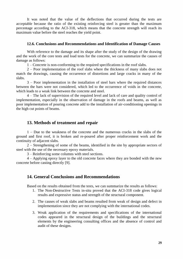
It was noted that the value of the deflections that occurred during the tests are
acceptable because the ratio of the existing reinforcing steel is greater than the maximum
percentage according to the ACI-318, which means that the concrete strength will reach its
maximum value before the steel reaches the yield point.
12.6. Conclusions and Recommendations and Identification of Damage Causes
With reference to the damage and its shape after the study of the design of the drawing
and the work of the core tests and load tests for the concrete, we can summarize the causes of
damage as follows:
1 – Concrete is non-conforming to the required specifications in the roof slabs.
2 – Poor implementation of the roof slabs where the thickness of many slabs does not
match the drawings, causing the occurrence of distortions and large cracks in many of the
slabs.
3 – Poor implementation in the installation of steel bars where the required distances
between the bars were not considered, which led to the occurrence of voids in the concrete,
which leads to a weak link between the concrete and steel.
4 – The lack of supervision of the required level and lack of care and quality control of
implementation, especially in the observation of damage in the roofs and beams, as well as
poor implementation of pouring concrete add to the installation of air-conditioning openings in
the high cut points of beams.
13. Methods of treatment and repair
1 – Due to the weakness of the concrete and the numerous cracks in the slabs of the
ground and first roof, it is broken and re-poured after proper reinforcement work and the
continuity of adjacent slabs.
2 – Strengthening of some of the beams, identified in the site by appropriate sectors of
steel with the use of the necessary epoxy materials.
3 – Reinforcing some columns with steel sections.
4 – Applying epoxy layer to the old concrete faces where they are bonded with the new
concrete before casting directly [9].
14. General Conclusions and Recommendations
Based on the results obtained from the tests, we can summarize the results as follows:
1. The Non-Destructive Tests in-situ proved that the ACI-318 code gives logical
results and expressive status and strength of the structural component.
2. The causes of weak slabs and beams resulted from weak of design and defect in
implementation since they are not complying with the international codes.
3. Weak application of the requirements and specifications of the international
codes appeared in the structural design of the buildings and the structural
elements by the engineering consulting offices and the absence of control and
audit of these designs.

30
4. Weak supervision and checking on the construction contracting companies to
apply the technical conditions appeared in design and strict compliance with the
drawings and technical specifications of the construction and buildings.
5. The repairing works of the structures are not useful because existing cracks and
deflections exceeded the allowable limit during the test. In addition, the
appearance of cracks and deflections in the slabs and the presence of vibrations
was dangerous in some of the slabs and some of the beams.
6. We recommend that the contractors selected for a project should be classified
professionally and registered in the committee of construction industry.
7. The results showed that two decades later the development of the construction
technology from design or implementation was little.
REFERENCES
1. Galati, N., et al. In-situ Evaluation of Two Concrete Slab Systems. I: Load
Determination and Loading Procedure. Journal of Performance of Constructed Facilities, 2008.
22(4): p. 207-216.
2. Goble, G. G. Geotechnical Related Development and Implementation of Load and
Resistance Factor Design (LRFD) Methods. Vol. 276. 1999: Transportation Research Board.
3. Galati, N., T. Alkhrdaji. In Situ Evaluation of Structures Using Load Testing, in
Forensic Engineering 2009: Pathology of the Built Environment. 2010. p. 657-667.
4. Mettemeyer, M., A. Nanni. Center for Infrastructure Engineering Studies.
5. Luping, T., L.-O. Nilsson. Rapid Determination of the Chloride Diffusivity in
Concrete by Applying an Electric Field. Materials Journal, 1993. 89(1): p. 49-53.
6. Ridge, A. R., P. H. Ziehl. Evaluation of Strengthened Reinforced Concrete Beams:
Cyclic Load Test and Acoustic Emission Methods. ACI Structural Journal, 2006. 103(6): p.
832.
7. Abdulahad, E. Developing a National System for the Investigation of the Structures
in Symposium of the Bulgarian Construction Chamber Bulgaria. 2014: Sofia, Bulgaria.
8. Illidge, F. A. B. Acoustic Emission Techniques and Cyclic Load Testing for Integrity
Evaluation of Self-compacting Normal and Self-compacting Lightweight Prestressed Concrete
Girders. 2010, University of South Carolina.
9. Abdulahad, E. Essence and Issues Affecting the Operation of the National Service of
Operational Reliability, in Symposium of the Bulgarian Construction Chamber, Bulgaria 2014:
Sofia, Bulgaria.
10. Committee, A. Institute, and I.O.f. Standardization. Building Code Requirements for
Structural Concrete (ACI 318-08) and Commentary. 2008. American Concrete Institute.
11. Committee, A. Building Code Requirements for Structural Concrete (ACI 318-14)
and Commentary. ACI, Farmington Hills, United States, 2014.
12. ACI Committee 318. American Concrete Institute, Building Code Requirements for
Structural Concrete and Commentary, (ACI 318-95). 1995.

31
ОЦЕНКА НА НОСИМОСПОСОБНОСТТА НА
СТОМАНОБЕТОННИ ПЛОЧИ ПО БЕЗРАЗРУШИТЕЛНИ МЕТОДИ
И АНАЛИЗ НА ПРИЧИНИТЕ ЗА ТЯХНОТО РАЗРУШЕНИЕ
И. Марков1, М. Ал Зухайли2
Ключови думи: стоманобетонни конструкции, полеви тестове, изпитвания на
натоварването, ядрен тест, in situ тестове, бетонни плочи
РЕЗЮМЕ
Основната цел на настоящата статия е да се направи оценка на безопасността и
експлоатационните качества на съществуващата структурна система чрез структурна
оценка на якостта чрез безразрушителни тестове за структурата на плочи от стоманобе-
тонни конструкции и анализ на причините за отказ на покривните плочи (RC).
В тази статия са разгледани три случая на покривни плочи (двупосочна плоча,
еднопосочна плоча) от три вили в Кувейт. Тези вили са построени през 2017, 2007 и 1997 г.,
съответно.
Наблюдава се слабост в якостта на бетона и отклонението на покривите, а в някои
от плочите и някои от гредите се появяват пукнатини.
Тестовете (изпитване на натоварване, ядрен тест) бяха проведени съгласно ACI-
318, за да се знае, че съответстват на якостта на съществуващия бетон и дали е безопасно
или не.
В края на статията тестовете дадоха добри резултати, за да се оцени носимоспо-
собността на стоманобетоновата конструкцията. Съществуват две основни причини за
дефекти на две плочи: първо – некачествено изпълнение от страна на възложителя и
несъответствието с изискваните технически спецификации, а втората причина са изчис-
лителни грешки и недобър контрол от страна на строителния надзор.
1 Иван Марков, проф. д-р инж., кат. „Строителна механика“, УАСГ, бул. „Хр. Смирненски“ № 1,
1046 София, e-mail: [email protected] 2 Мохамед Ал Зухайли, докторант, кат. „Строителна механика“, УАСГ, бул. „Хр. Смирненски“
№ 1, 1046 София, e-mail: [email protected]