Embed Size (px)
Citation preview

-1- Structural Stability and Factor of Safety Assessment Ponds 1N, 1S, 2S, and 3S - Will County Station
CEC Project 312-192.0230 September 2021
STRUCTURAL STABILITY AND FACTOR OF SAFETY ASSESSMENT ASH PONDS 1N, 1S, 2S, AND 3S, WILL COUNTY STATION
SEPTEMBER 2021
This Structural Stability and Factor of Safety Assessment report has been prepared pursuant to the coal combustion residuals (CCR) rule codified in Title 35 of the Illinois Administrative Code, Section 845.440(a) effective as of April 21, 2021 for North Ash Pond 1 and South Ash Pond 1, South Ash Pond 2, and South Ash Pond 3 (herein referred to as Pond(s) 1N, 1S, 2S, and 3S) at Will County Station in Romeoville, Illinois (Station). The purpose of this project is to perform the initial structural stability and factor of safety assessments for the ponds by a licensed professional engineer. Civil & Environmental Consultants, Inc. (CEC) completed this structural stability and factor of safety assessment as described in the following sections.
REGULATION REQUIREMENTS - SECTIONS 845.450 AND 845.460
In accordance with Sections 845.450 and 845.460, owners or operator of a CCR impoundment are required to conduct initial and annual structural stability assessments to document whether the design, construction, operation, and maintenance of the CCR surface impoundment is consistent with recognized and generally accepted engineering practices for the maximum volume of CCR and CCR wastewater which can be impounded; and to conduct an initial and annual safety factor assessment for each CCR surface impoundment and document whether the calculated factors of safety for each CCR surface impoundment achieve the minimum safety factors specified for the critical cross section of the embankment.
SITE CONDITIONS
Ponds 1N, 1S, 2S, and 3S are located at Will County Station, 529 East 135th Street in Romeoville, Will County, Illinois and situated south of 135th Street between the Des Plaines River and the Chicago Sanity and Ship Canal, see Figure 1. Basic information for each of the ponds are provided in Table 1. The ponds are of similar construction, size, and age. Each pond is constructed with a concrete weir spillway along the west half. Gravel access roads are located along the sides of the ponds.
Table 1 - Ash Pond Construction
Pond ID Year of Original Construction
Dimension (ft x ft)
Depth (ft)
Capacity (ft3) Status
Pond 1N 1977 167 x 333 7 520,000 Closed Pond 1S 1977 300 x 195 7 460,000 Closed Pond 2S 1977 350 x 178 7 510,000 Active Pond 3S 1977 234 x 322 7 530,000 Inactive

-2- Structural Stability and Factor of Safety Assessment Ponds 1N, 1S, 2S, and 3S - Will County Station
CEC Project 312-192.0230 September 2021
Based on information provided by Station personnel, the ponds were originally constructed in 1977, and have not undergone significant changes in the geometry. The original operation was designed to receive bottom ash via sluicing with wastewater treated in the wastewater treatment plant and discharged to the Chicago Sanitary and Ship Canal through the permitted National Pollutant Discharge Elimination System Outfall 002.
Ponds 1N and 1S were closed after the shutdown of Unit 1 and Unit 2, respectively. Pond 2S is still active, and at the time of our inspection, Pond 3S was inactive. The ponds are inspected weekly by the environmental specialist including checking the water level in the ponds.
STRUCTURAL STABILITY ASSESSMENT - SECTION 845.450
The following sections describe the structural stability assessment.
3.1 Stable Foundation and Abutments - Section 845.450(a)(1)
This assessment indicates the soils forming the pond foundations are stable. Soils data from soil boring logs and monitoring well logs within the vicinity of the ponds show the foundations consist of random sandy clay and gravel fill over weathered limestone bedrock. Inspection of the ponds did not show signs of distress due to settlement of the underlying foundation soils.
The ponds are partially incised and supported by earthen embankments. These type of basins constructed with earthen berms do not require abutments, and therefore consideration of abutment design, construction, and operation is not required.
3.2 Adequate Slope Protection - Section 845.450(a)(2)
Ponds 1N, 1S, 2S, and 3S are constructed with concrete overflows on the south end of each pond and the earthen bottom and sidewalls are protected with Poz-o-Pac liner. Additionally, Ponds 2S and 3S are also protected with a flexible membrane liner that provides adequate protection of the interior slopes against surface erosion, wave action, and adverse effects of sudden drawdown. From our inspection, Pond 2S has a protective layer comprised of concrete filled flexible reinforcement grid which is placed over a 6-inch warning layer, 12-inch cushion layer, and a 60 mil textured flexible membrane liner; while Pond 3S has been lined with flexible membrane liner. Our inspection of the ponds showed no signs of erosion.
3.3 Dike Compaction - Section 845.450(a)(3)
As-built construction documents for the initial construction of the ponds are unavailable. It would be standard practice for the dikes to be mechanically compacted to a density sufficient to withstand the range of loading conditions in the ponds. This is supported by the consideration that the ponds have been in operation since the 1977, and that the station has no record of observed distresses or

-3- Structural Stability and Factor of Safety Assessment Ponds 1N, 1S, 2S, and 3S - Will County Station
CEC Project 312-192.0230 September 2021
repairs. Furthermore, the initial inspection of the dikes did not shows signs of distress that would be indicative of improperly placed and/or loosely compacted soils.
3.4 Downstream Slope Protection - Section 845.450(a)(4)
Consistent with Section 845.430, the basin slope protection consists of a combination of riprap and vegetative cover over the downstream slopes. Inspection shows the slope protection is maintained; protective against surface erosion, wave action, and adverse effect of rapid drawdown. At the time of inspection, the woody vegetation was observed on the downstream slope. Grassy vegetation did not exceed 12 inches in height.
3.5 Spillway - Section 845.450(a)(5)
Although each of the ponds are constructed with a concrete overflow connected to the on-site wastewater treatment plant, the ponds have not been designed or constructed with a spillway. Section 845.450 specifies a single spillway or a combination of spillways configured as specified in Subsection (a)(5)(A), and that the combined capacity of all spillways must be designed, constructed, operated, and maintained to adequately manage flow during and following the peak discharge from the event specified in Subsection (a)(5)(B). Not having an spillway is considered a deficiency in accordance with the Section 845.450(a)(5). Our inspection shows the ponds have been constructed and operated without incident since 1977, without any spillway, and that water levels are maintained at the level of the overflow.
3.6 Structural Integrity of Hydraulic Structures - Section 845.450(a)(6)
Although each of the ponds are constructed with a concrete overflow connected to the wastewater treatment plant, the pipe leading from the overflow is either a 36-inch (Ponds 2S and 3S) or 48-inch (Ponds 1N and 1S) diameter pipe that passes through earthen embankment. At the time of our inspection, the water flowed into the pipe and evidence showing the structural integrity of the pipe free of significant deterioration, deformation, distortion, bedding deficiencies, sedimentation, and debris could not be made. At the time of this report, inspection reports for the overflow were unavailable.
3.7 Down Stream Slopes Adjacent To Water Bodies - Section 845.450(a)(7)
The Des Plaines River is downstream of the ponds and a stability analysis was performed for both a low pool and rapid draw down condition. The stability analysis shows that the embankment is designed and constructed to maintain stability during both low pool and rapid draw down conditions.

-4- Structural Stability and Factor of Safety Assessment Ponds 1N, 1S, 2S, and 3S - Will County Station
CEC Project 312-192.0230 September 2021
3.8 Structural Stability Assessment Deficiencies
Structural deficiencies associated with the ponds were not identified during this initial structural stability assessment. Inspection records for the pipe were unavailable. Although our inspection did not identify distress that would suggest the existence of a structural deficiency, the overflow pipe should be inspected in accordance with Section 845.450(a)(6).
3.9 Annual Inspection Requirement
In completing the initial structural stability assessment, the ponds were inspected for signs of distress that would have the potential to disrupt operation and safety. No signs of distress that would have the potential to disrupt operation and safety of the ponds were identified. This inspection can suffice for the 2021 inspection.
SAFETY FACTOR ASSESSMENT - SECTION 845.460
In accordance with Section 845.460, the owner or operator of a CCR surface impoundment must conduct initial and annual safety factor assessments for each CCR surface impoundment and document whether the calculated factors of safety for each CCR surface impoundment achieve the minimum safety factors specified for the critical cross section of the embankment. The critical cross section is the cross section anticipated to be the most susceptible of all cross sections to structural failure based on appropriate engineering considerations, including loading conditions. The safety factor assessments must be supported by appropriate engineering calculations.
4.1 Slope Stability Methodology
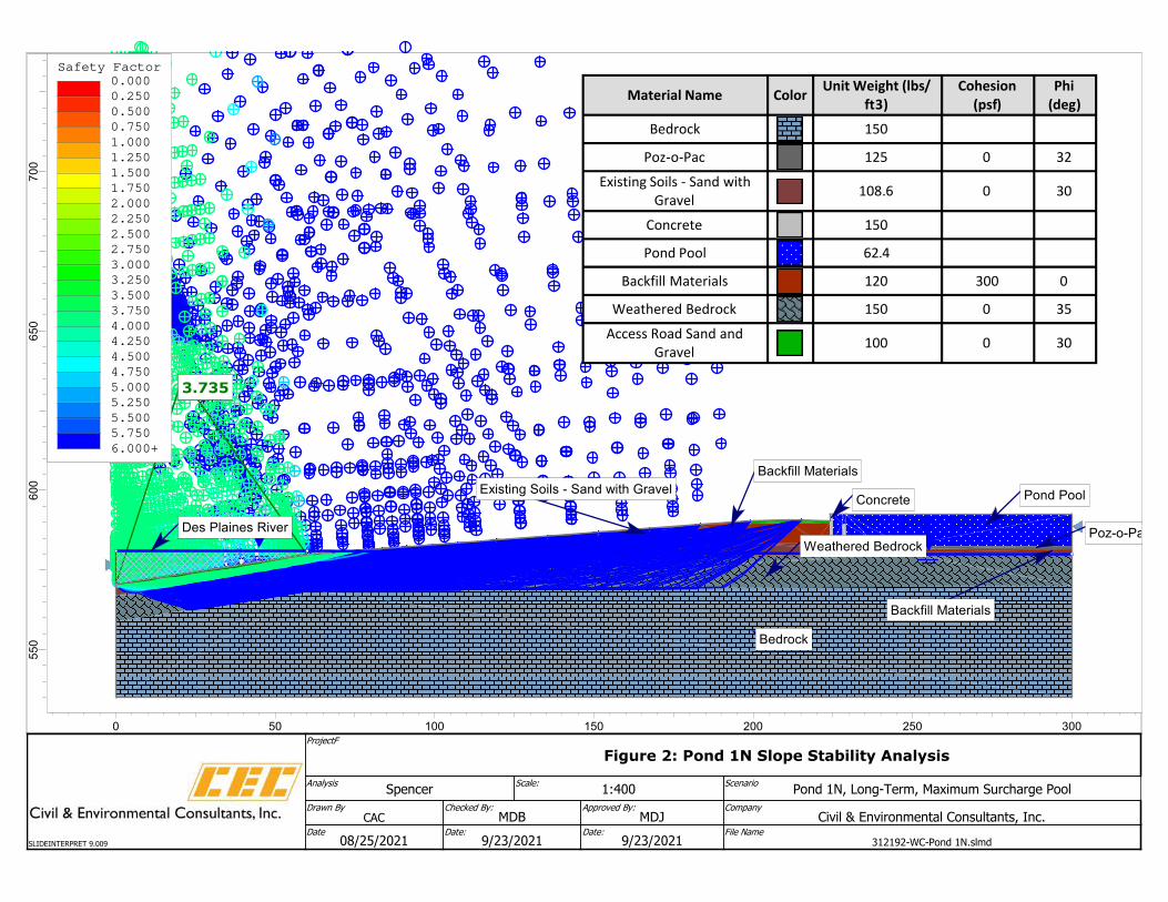
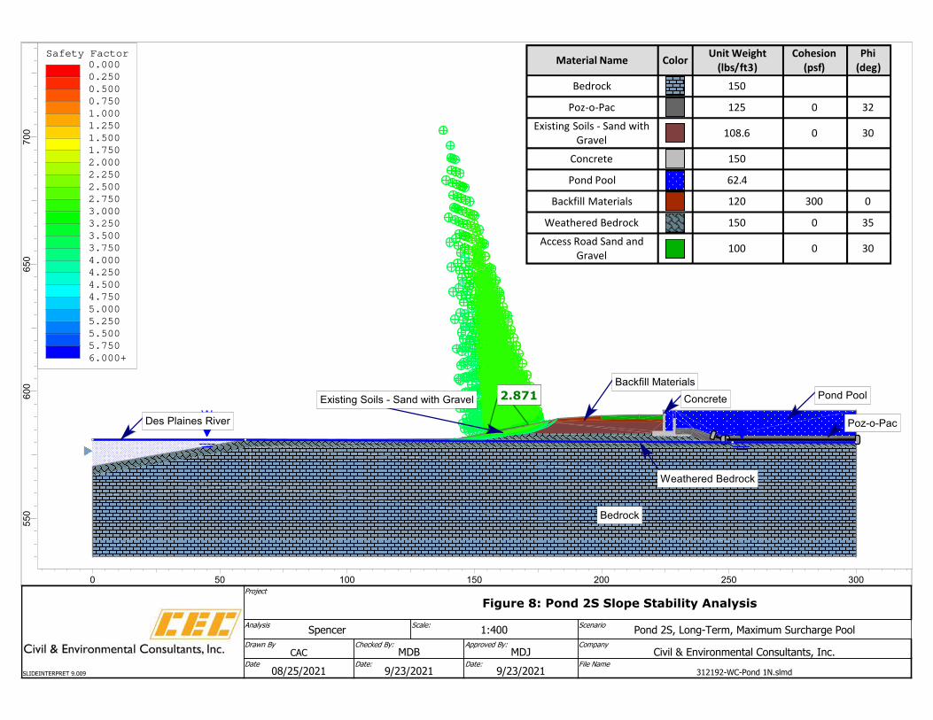
Slope stability software Slide2 was used to calculate the minimum factor of safety for each pond at Cross Section 1N-1N, 1S-1S, 2S-2S, and 3S-3S, respectively. The program uses 2D limit equilibrium methods to determine the minimum factor of safety against slope instability. The auto-refine, non-circular search method with optimization was used utilizing Spencer’s method to calculate the factor of safety for each design criteria scenario, as discussed below. For each section analyzed, the program searches for the sliding surface that procures the lowest factor of safety which is defined as the ratio of the shear forces and moment resisting movement along the sliding surface to the forces and moments driving the instability.
Soil data provided by the station personnel was used to develop soil properties for the slope stability analysis. The data shows the soil materials in the vicinity of the ponds consists of up to approximately 5 feet of random clay fill overlying weathered and unweathered limestone bedrock.
4.2 Slope Stability Analysis - Section 845.460
Four cases were analyzed to satisfy the safety factor assessment as per Section 845.460(a)(2) through (a)(4).

-5- Structural Stability and Factor of Safety Assessment Ponds 1N, 1S, 2S, and 3S - Will County Station
CEC Project 312-192.0230 September 2021
4.2.1 Static, Long-Term - Section 845.460(a)(2)
The static, long-term condition with the maximum surcharge loading on the embankment was evaluated. The static, long-term analysis included a pool elevation at 592.5 feet mean sea level and a groundwater elevation at 580.5 feet mean sea level.
4.2.2 Static, Maximum Storage Pool - Section 845.460(a)(3)
The static, long-term, maximum storage pool condition with the maximum surcharge loading on the embankment was evaluated. The static, long-term analysis included a pool elevation set at the lowest points of the embankment crest, 589.5 feet mean sea level, and a groundwater elevation at 580.5 feet mean sea level.
4.2.3 Seismic - Section 845.460(a)(4)
Seismic analysis was performed by incorporating pseudo static seismic loading scenarios in the long-term global stability analysis calculations. A pseudo-static seismic horizontal load was applied to the long-term maximum storage pool loading condition model.
The seismic factor of safety is defined in the proposed CCR regulations as “the factor of safety (safety factor) determined using analysis under earthquake conditions using the peak ground acceleration (PGA) for a seismic event with a 2% probability of exceedance in 50 years, equivalent to a return period of approximately 2,500 years, based on the U.S. Geological Survey (USGS) seismic hazard maps for seismic events with this return period for the region where the CCR surface impoundment is located”.
4.2.4 Liquefaction - Section 845.460(a)(5)
For dikes constructed of soils susceptible to liquefaction, the calculated liquefaction factor of safety must equal or exceed 1.20. Soils with potential for liquefaction typically consist of poorly drained fine-grained soils. Soil boring data indicate that the embankment and foundation soils consist of random sandy clay and gravel fill over shallow weathered limestone bedrock. These soil types are not susceptible to liquefaction. Additionally, the Poz-o-Pac liner system makes it unlikely the embankment would become saturated or inundated. Because the likelihood of liquefaction and associated shear strength loss of the embankment soils is very low, the liquefaction condition is represented by the static factor of safety analysis and a separate analysis was not performed.
4.3 Factor of Safety Assessment Results
Results of the slope stability analysis for the critical cross section of the ponds are summarized in Table 2, below, and presented in Figures 1 through 13. The results meet the factor of safety requirements presented in 845.460(a)(2) through (4).

-6- Structural Stability and Factor of Safety Assessment Ponds 1N, 1S, 2S, and 3S - Will County Station
CEC Project 312-192.0230 September 2021
Table 2: Safety Factor Results - Ponds 1N, 1S, 2S, and 3S
Loading Condition Required FS
Calculated Factor of safety 1N 1S 2S 3S
Static, Long-Term 845.460(a)(2) 1.50 3.76 2.87 2.87 3.48
Static, Maximum Storage Pool 845.460(a)(3) 1.40 3.76 2.87 2.87 3.48
Seismic 845.460(a)(4) 1.00 1.89 1.77 2.11 2.56
Liquefaction 845.460(a)(5) 1.20 >1.20 >1.20 >1.20 >1.20
LIMITATIONS AND CERTIFICATION
This initial Structural Stability and Factor of Safety Assessment report was prepared to meet the requirements of Sections 845.450 and 845.460 of the Illinois Administrative Code draft Title 35 Subtitle G Subchapter I Subchapter j Coal Combustion Waste Surface Impoundments, and was prepared under the direction of Mr. M. Dean Jones, P.E.
By affixing my seal to this, I do hereby certify to the best of my knowledge, information, and belief that the information contained in this report is true and correct. I further certify I am licensed to practice in the State of Illinois and that it is within my professional expertise to verify the correctness of the information. I am aware that there are significant penalties for submitting false information, including the possibility of fines and imprisonment.
Signature:
Name: M. Dean Jones, P.E.
Date of Certification: September 23, 2021
Illinois Professional Engineer No.: 062-051317
Expiration Date: November 30, 2021
Enclosure: Figures

FIGURES

2S
2S
3S
1S
1N
1N
3S
1S
DATE: DWG SCALE:
DRAWN BY: CHECKED BY: APPROVED BY:
PROJECT NO:
FIGURE NO.:
SITE PLAN WITH CROSS-SECTIONS
312-192.02301"=100'SEPTEMBER 2021CAC CAC MDJ*
1
MIDWEST GENERATION LLCWILL COUNTY STATION
PONDS 1N, 1S, 2S, AND 3S SLOPE STABILITYROMEOVILLE, WILL COUNTY, ILLINOIS
1230 East Diehl Road, Suite 200 - Naperville, IL 60563630-963-6026 · 877-963-6026
www.cecinc.com
NORTH
1N 1N
REFERENCES
LEGEND
MW-10 APPROXIMATE EXISTINGMONITORING WELL LOCATION(PATRICK, 2010)
APPROXIMATE SOIL BORINGLOCATION (KPRG, 2005)
WC-GT-2
SLOPE STABILITY CROSS SECTION
MW-11 APPROXIMATE EXISTINGMONITORING WELL LOCATIONKPRG, 2015)
*HAND SIGNATURE ON FILE
3.7353.7353.7353.735
W W
Bedrock
Weathered Bedrock
Pond Pool
Poz-o-Pac
Backfill Materials
Existing Soils - Sand with GravelConcrete
Des Plaines River
Backfill Materials
Phi
(deg)
Cohesion
(psf)
Unit Weight (lbs/
ft3)ColorMaterial Name
150Bedrock
320125Poz-o-Pac
300108.6Existing Soils - Sand with
Gravel
150Concrete
62.4Pond Pool
0300120Backfill Materials
350150Weathered Bedrock
300100Access Road Sand and
Gravel
Safety Factor
0.000
0.250
0.500
0.750
1.000
1.250
1.500
1.750
2.000
2.250
2.500
2.750
3.000
3.250
3.500
3.750
4.000
4.250
4.500
4.750
5.000
5.250
5.500
5.750
6.000+
70
06
50
60
05
50
0 50 100 150 200 250 300
ScenarioPond 1N, Long-Term, Maximum Surcharge Pool
Scale:1:400
AnalysisSpencer
CompanyCivil & Environmental Consultants, Inc.
Checked By:MDB
Approved By:MDJ
Drawn ByCAC
File Name312192-WC-Pond 1N.slmd
Date:9/23/2021
Date:9/23/2021
Date08/25/2021
ProjectF
Figure 2: Pond 1N Slope Stability Analysis
SLIDEINTERPRET 9.009
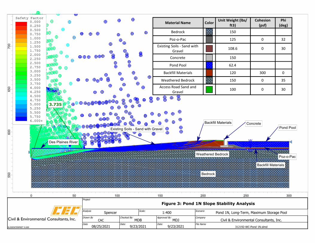
3.7353.7353.7353.735
W W
Bedrock
Weathered Bedrock
Pond Pool
Backfill Materials
Poz-o-Pac
Backfill Materials
Existing Soils - Sand with Gravel
Concrete
Des Plaines River
Phi
(deg)
Cohesion
(psf)
Unit Weight (lbs/
ft3)ColorMaterial Name
150Bedrock
320125Poz-o-Pac
300108.6Existing Soils - Sand with
Gravel
150Concrete
62.4Pond Pool
0300120Backfill Materials
350150Weathered Bedrock
300100Access Road Sand and
Gravel
Safety Factor
0.000
0.250
0.500
0.750
1.000
1.250
1.500
1.750
2.000
2.250
2.500
2.750
3.000
3.250
3.500
3.750
4.000
4.250
4.500
4.750
5.000
5.250
5.500
5.750
6.000+
70
06
50
60
05
50
0 50 100 150 200 250 300
ScenarioPond 1N, Long-Term, Maximum Storage Pool
Scale:1:400
AnalysisSpencer
CompanyCivil & Environmental Consultants, Inc.
Checked By:MDB
Approved By:MDJ
Drawn ByCAC
File Name312192-WC-Pond 1N.slmd
Date:9/23/2021
Date:9/23/2021
Date08/25/2021
Project
Figure 3: Pond 1N Slope Stability Analysis
SLIDEINTERPRET 9.009

1.8901.8901.8901.890
W W
Phi (deg)Cohesion
(psf)
Unit Weight (lbs/
ft3)ColorMaterial Name
150Bedrock
320125Poz-o-Pac
300108.6Existing Soils - Sand with
Gravel
150Concrete
62.4Pond Pool
0300120Backfill Materials
350150Weathered Bedrock
300100Access Road Sand and Gravel
Bedrock
Weathered Bedrock
Pond Pool
Poz-o-Pac
Backfill Materials
Existing Soils - Sand with Gravel Concrete
Des Plaines River
0.069
Safety Factor
0.000
0.250
0.500
0.750
1.000
1.250
1.500
1.750
2.000
2.250
2.500
2.750
3.000
3.250
3.500
3.750
4.000
4.250
4.500
4.750
5.000
5.250
5.500
5.750
6.000+
70
06
50
60
05
50
0 50 100 150 200 250 300
ScenarioPond 1N, Long-Term, Maximum Storage Pool - Seismic
Scale:1:400
AnalysisSpencer
CompanyCivil & Environmental Consultants, Inc.
Checked By:MDB
Approved By:MDJ
Drawn ByCAC
File Name312192-WC-Pond 1N.slmd
Date:9/23/2021
Date:9/23/2021
Date08/25/2021
Project
Figure 4: Pond 1N Slope Stability Analysis
SLIDEINTERPRET 9.009

2.8712.8712.8712.871
W W
Phi
(deg)
Cohesion
(psf)
Unit Weight (lbs/
ft3)ColorMaterial Name
150Bedrock
320125Poz-o-Pac
300108.6Existing Soils - Sand with
Gravel
150Concrete
62.4Pond Pool
0300120Backfill Materials
350150Weathered Bedrock
300100Access Road Sand and Gravel
Bedrock
Weathered Bedrock
Pond Pool
Poz-o-Pac
Backfill Materials
Existing Soils - Sand with GravelConcrete
Des Plaines River
Safety Factor
0.000
0.250
0.500
0.750
1.000
1.250
1.500
1.750
2.000
2.250
2.500
2.750
3.000
3.250
3.500
3.750
4.000
4.250
4.500
4.750
5.000
5.250
5.500
5.750
6.000+
70
06
50
60
05
50
0 50 100 150 200 250 300
ScenarioPond 1S, Long-Term, Maximum Surcharge Pool
Scale:1:400
AnalysisSpencer
CompanyCivil & Environmental Consultants, Inc.
Checked By:MDB
Approved By:MDJ
Drawn ByCAC
File Name312192-WC-Pond 1N.slmd
Date:9/23/2021
Date:9/23/2021
Date08/25/2021
Project
Figure 5: Pond 1S Slope Stability Analysis
SLIDEINTERPRET 9.009

2.8712.8712.8712.871
W W
Phi (deg)Cohesion (psf)Unit Weight (lbs/
ft3)ColorMaterial Name
150Bedrock
320125Poz-o-Pac
300108.6Existing Soils - Sand with
Gravel
150Concrete
62.4Pond Pool
0300120Backfill Materials
350150Weathered Bedrock
300100Access Road Sand and Gravel
Bedrock
Weathered Bedrock
Pond Pool
Poz-o-Pac
Backfill Materials
Existing Soils - Sand with GravelConcrete
Des Plaines River
Safety Factor
0.000
0.250
0.500
0.750
1.000
1.250
1.500
1.750
2.000
2.250
2.500
2.750
3.000
3.250
3.500
3.750
4.000
4.250
4.500
4.750
5.000
5.250
5.500
5.750
6.000+
70
06
50
60
05
50
0 50 100 150 200 250 300
ScenarioPond 1S, Long-Term, Maximum Storage Pool
Scale:1:400
AnalysisSpencer
CompanyCivil & Environmental Consultants, Inc.
Checked By:MDB
Approved By:MDJ
Drawn ByCAC
File Name312192-WC-Pond 1N.slmd
Date:9/23/2021
Date:9/23/2021
Date08/25/2021
Project
Figure 6: Pond 1S Slope Stability Analysis
SLIDEINTERPRET 9.009

1.7701.7701.7701.770
W W
Phi
(deg)
Cohesion
(psf)
Unit Weight (lbs/
ft3)ColorMaterial Name
150Bedrock
320125Poz-o-Pac
300108.6Existing Soils - Sand with
Gravel
150Concrete
62.4Pond Pool
0300120Backfill Materials
350150Weathered Bedrock
300100Access Road Sand and
Gravel
Bedrock
Weathered Bedrock
Pond Pool
Poz-o-Pac
Backfill MaterialsExisting Soils - Sand with Gravel
ConcreteDes Plaines River
0.069
Safety Factor
0.000
0.250
0.500
0.750
1.000
1.250
1.500
1.750
2.000
2.250
2.500
2.750
3.000
3.250
3.500
3.750
4.000
4.250
4.500
4.750
5.000
5.250
5.500
5.750
6.000+
70
06
50
60
05
50
0 50 100 150 200 250 300
ScenarioPond 1S, Long-Term, Maximum Storage Pool - Seismic
Scale:1:400
AnalysisSpencer
CompanyCivil & Environmental Consultants, Inc.
Checked By:MDB
Approved By:MDJ
Drawn ByCAC
File Name312192-WC-Pond 1N.slmd
Date:9/23/2021
Date:9/23/2021
Date08/25/2021
Project
Figure 7: Pond 1S Slope Stability Analysis
SLIDEINTERPRET 9.009
2.8712.8712.8712.871
W W
Bedrock
Weathered Bedrock
Pond Pool
Poz-o-Pac
Backfill Materials
Existing Soils - Sand with Gravel Concrete
Des Plaines River
Phi
(deg)
Cohesion
(psf)
Unit Weight
(lbs/ft3)ColorMaterial Name
150Bedrock
320125Poz-o-Pac
300108.6Existing Soils - Sand with
Gravel
150Concrete
62.4Pond Pool
0300120Backfill Materials
350150Weathered Bedrock
300100Access Road Sand and
Gravel
Safety Factor
0.000
0.250
0.500
0.750
1.000
1.250
1.500
1.750
2.000
2.250
2.500
2.750
3.000
3.250
3.500
3.750
4.000
4.250
4.500
4.750
5.000
5.250
5.500
5.750
6.000+
70
06
50
60
05
50
0 50 100 150 200 250 300
ScenarioPond 2S, Long-Term, Maximum Surcharge Pool
Scale:1:400
AnalysisSpencer
CompanyCivil & Environmental Consultants, Inc.
Checked By:MDB
Approved By:MDJ
Drawn ByCAC
File Name312192-WC-Pond 1N.slmd
Date:9/23/2021
Date:9/23/2021
Date08/25/2021
Project
Figure 8: Pond 2S Slope Stability Analysis
SLIDEINTERPRET 9.009

2.8712.8712.8712.871
W W
Phi
(deg)
Cohesion
(psf)
Unit Weight
(lbs/ft3)ColorMaterial Name
150Bedrock
320125Poz-o-Pac
300108.6Existing Soils - Sand
with Gravel
150Concrete
62.4Pond Pool
0300120Backfill Materials
350150Weathered Bedrock
300100Access Road Sand and
Gravel
Bedrock
Weathered Bedrock
Pond Pool
Poz-o-Pac
Backfill MaterialsExisting Soils - Sand with Gravel
Concrete
Des Plaines River
Safety Factor
0.000
0.250
0.500
0.750
1.000
1.250
1.500
1.750
2.000
2.250
2.500
2.750
3.000
3.250
3.500
3.750
4.000
4.250
4.500
4.750
5.000
5.250
5.500
5.750
6.000+
70
06
50
60
05
50
0 50 100 150 200 250 300
ScenarioPond 2S, Long-Term, Maximum Storage Pool
Scale:1:400
AnalysisSpencer
CompanyCivil & Environmental Consultants, Inc.
Checked By:MDB
Approved By:MDJ
Drawn ByCAC
File Name312192-WC-Pond 1N.slmd
Date:9/23/2021
Date:9/23/2021
Date08/25/2021
Project
Figure 9: Pond 2S Slope Stability Analysis
SLIDEINTERPRET 9.009
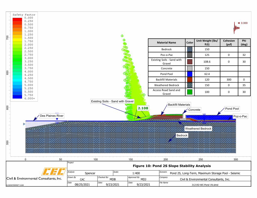
2.1082.1082.1082.108
W W
Phi
(deg)
Cohesion
(psf)
Unit Weight (lbs/
ft3)ColorMaterial Name
150Bedrock
320125Poz-o-Pac
300108.6Existing Soils - Sand with
Gravel
150Concrete
62.4Pond Pool
0300120Backfill Materials
350150Weathered Bedrock
300100Access Road Sand and
Gravel
Bedrock
Weathered Bedrock
Pond Pool
Poz-o-Pac
Backfill MaterialsExisting Soils - Sand with Gravel
Concrete
Des Plaines River
0.069
Safety Factor
0.000
0.250
0.500
0.750
1.000
1.250
1.500
1.750
2.000
2.250
2.500
2.750
3.000
3.250
3.500
3.750
4.000
4.250
4.500
4.750
5.000
5.250
5.500
5.750
6.000+
70
06
50
60
05
50
0 50 100 150 200 250 300
ScenarioPond 2S, Long-Term, Maximum Storage Pool - Seismic
Scale:1:400
AnalysisSpencer
CompanyCivil & Environmental Consultants, Inc.
Checked By:MDB
Approved By:MDJ
Drawn ByCAC
File Name312192-WC-Pond 1N.slmd
Date:9/23/2021
Date:9/23/2021
Date08/25/2021
Project
Figure 10: Pond 2S Slope Stability Analysis
SLIDEINTERPRET 9.009
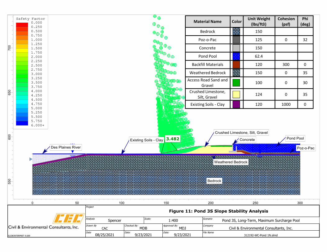
3.4823.4823.4823.482
W W
Phi
(deg)
Cohesion
(psf)
Unit Weight
(lbs/ft3)ColorMaterial Name
150Bedrock
320125Poz-o-Pac
150Concrete
62.4Pond Pool
0300120Backfill Materials
350150Weathered Bedrock
300100Access Road Sand and
Gravel
350124Crushed Limestone,
Silt, Gravel
01000120Existing Soils - Clay
Bedrock
Weathered Bedrock
Pond Pool
Poz-o-Pac
Crushed Limestone, Silt, Gravel
Existing Soils - Clay Concrete
Des Plaines River
Safety Factor
0.000
0.250
0.500
0.750
1.000
1.250
1.500
1.750
2.000
2.250
2.500
2.750
3.000
3.250
3.500
3.750
4.000
4.250
4.500
4.750
5.000
5.250
5.500
5.750
6.000+
70
06
50
60
05
50
0 50 100 150 200 250 300
ScenarioPond 3S, Long-Term, Maximum Surcharge Pool
Scale:1:400
AnalysisSpencer
CompanyCivil & Environmental Consultants, Inc.
Checked By:MDB
Approved By:MDJ
Drawn ByCAC
File Name312192-WC-Pond 1N.slmd
Date:9/23/2021
Date:9/23/2021
Date08/25/2021
Project
Figure 11: Pond 3S Slope Stability Analysis
SLIDEINTERPRET 9.009

3.5093.5093.5093.509
W W
Phi
(deg)
Cohesion
(psf)
Unit Weight (lbs/
ft3)ColorMaterial Name
150Bedrock
320125Poz-o-Pac
150Concrete
62.4Pond Pool
0300120Backfill Materials
350150Weathered Bedrock
300100Access Road Sand and Gravel
350124Crushed Limestone, Silt,
Gravel
01000120Existing Soils - Clay
Bedrock
Weathered Bedrock
Pond Pool
Crushed Limestone, Silt, Gravel
Concrete
Existing Soils - Clay
Poz-o-Pac
Backfill Materials
Des Plaines River
Safety Factor
0.000
0.250
0.500
0.750
1.000
1.250
1.500
1.750
2.000
2.250
2.500
2.750
3.000
3.250
3.500
3.750
4.000
4.250
4.500
4.750
5.000
5.250
5.500
5.750
6.000+
70
06
50
60
05
50
0 50 100 150 200 250 300
ScenarioPond 3S, Long-Term, Maximum Storage Pool
Scale:1:400
AnalysisSpencer
CompanyCivil & Environmental Consultants, Inc.
Checked By:MDB
Approved By:MDJ
Drawn ByCAC
File Name312192-WC-Pond 1N.slmd
Date:9/23/2021
Date:9/23/2021
Date08/25/2021
Project
Figure 12: Pond 3S Slope Stability Analysis
SLIDEINTERPRET 9.009

2.5742.5742.5742.574
W W
Phi
(deg)
Cohesion
(psf)
Unit Weight (lbs/
ft3)ColorMaterial Name
150Bedrock
320125Poz-o-Pac
150Concrete
62.4Pond Pool
0300120Backfill Materials
350150Weathered Bedrock
300100Access Road Sand and
Gravel
350124Crushed Limestone, Silt,
Gravel
01000120Existing Soils - Clay
Bedrock
Weathered Bedrock
Pond PoolCrushed Limestone, Silt, Gravel
Existing Soils - Clay
Backfill Materials
Poz-o-Pac
Des Plaines River
0.069
Safety Factor
0.000
0.250
0.500
0.750
1.000
1.250
1.500
1.750
2.000
2.250
2.500
2.750
3.000
3.250
3.500
3.750
4.000
4.250
4.500
4.750
5.000
5.250
5.500
5.750
6.000+
70
06
50
60
05
50
0 50 100 150 200 250 300
ScenarioPond 3S, Long-Term, Maximum Storage Pool - Seismic
Scale:1:400
AnalysisSpencer
CompanyCivil & Environmental Consultants, Inc.
Checked By:MDB
Approved By:MDJ
Drawn ByCAC
File Name312192-WC-Pond 1N.slmd
Date:9/23/2021
Date:9/23/2021
Date08/25/2021
Project
Figure 13: Pond 3S Slope Stability Analysis
SLIDEINTERPRET 9.009