Embed Size (px)
Citation preview

Pertanika J. Sci. & Techno!. 12(1): 103 - \13 (2004)ISSN: 0128-7680
© Universiti Putra Malaysia Press
Structural Response of Initially Loaded RC Beam toDifferent Retrofitting Techniques
Waleed A. Thanoon, M. S. Jaafar, J. Noorzaei,Mohd Razali Abdul Kadir & Thamer A. MohamedCivil Engineering Department, Faculty oj Engineering,
Universiti Putra Malaysia, 43400 UPM, Serdang, Selangor, Malaysia
Received: 18 November 2002
ABSTRAGr
Penambahan bilangan struktur konkrit yang rosak telah menggariskan peripentingnya memajukan teknik baik pulih yang boleh diterima. Kertas inimembentangkan kajian ke atas keIakuan struktur rasuk konkrit tetulang yangdibaik pulih dengan dua kaedah yang berbeza. Teknik pertama menggunakanCFRP sebagai pengukuh, sementara sistem prategasan luaran digunakan sebagaiteknik kedua. Spesimen dikenakan beban awal sehingga dua pertiga daripadabeban muktamad yang dijangka. Beban kemudian dilepaskan dan rasuk-rasuktersebut dibaik pulih dengan CFRP atau prategasan luaran. Spesimen dikenakandengan beban sehingga ke tahap gaga\. Respons struktur telah ditinjauberkenaan kelakuan retakan, hubungan beban-pesongan, kemuluran, agihanterikan, beban muktamad dan ragam kegagalan. Keputusan menunjukkanrespons yang serupa pada kedua-dua teknik tersebut. Oleh itu, konsep rekabentuk kenyal yang digunakan untuk konkrit prategasan boleh digunakanuntuk reka bentuk konkrit dengan CFRP.
ABSTRAGr
The increase in the large number of distressed reinforced concrete structureunderscores the importance of developing acceptable retrofitting techniques.This study investigates the structural behaviour of full scale reinforced concretebeams strengthened by two different techniques. The first technique used isthe strengthening of the beam by CFRP, while the second technique used is theexternal pre-stressing. The specimens were initially loaded to two-thirds of theirpredicted ultimate flexural capacity. They were then unloaded and strengthenedwith either CFRP or external prestressing. The beams were subsequentlysubjected to incremental loads until failure. The structural response of thetested specimens had been found in terms of their cracking behaviour, loaddeflection relationship, ductility, strain, distribution, ultimate load and failuremechanism. The results indicate similar structural response in both retrofittingtechniques at the ultimate range. Hence the concept of elastic design used inprestressed concrete members may be used for reinforced concrete membersstrengthened with CFRP.
Keywords: Loaded RC beam, retrofitting techniques, CFRP, structural response
INTRODUCTION
The repair of structurally deteriorated reinforced concrete structures becomesnecessary as the structural element ceases to provide satisfactory strength and
Waleed A. Thanoon, M. S. Jaafar, J. Noor/-aei, Mohd Ra7..ali Abdul Kadir & Thamer A. Mohamed
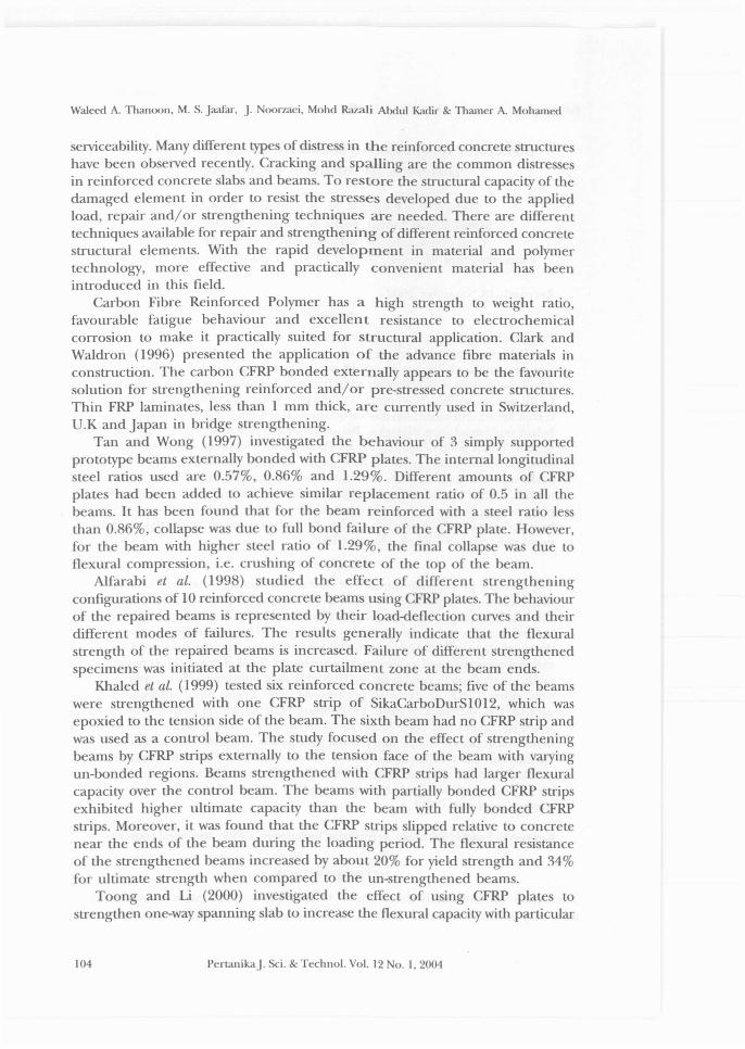
serviceability. Many different types of distress in the reinforced concrete structureshave been observed recently. Cracking and spalling are the common distressesin reinforced concrete slabs and beams. To restore the structural capacity of thedamaged element in order to resist the stresses developed due to the appliedload, repair and/or strengthening techniques are needed. There are differenttechniques available for repair and strengthening of different reinforced concretestructural elements. With the rapid development in material and polymertechnology, more effective and practically convenient material has beenintroduced in this field.
Carbon Fibre Reinforced Polymer has a high strength to weight ratio,favourable fatigue behaviour and excellent resistance to electrochemicalcorrosion to make it practically suited for structural application. Clark andWaldron (1996) presented the application of the advance fibre materials inconstruction. The carbon CFRP bonded externally appears to be the favouritesolution for strengthening reinforced and/or pre-stressed concrete structures.Thin FRP laminates, less than 1 mm thick, are currently used in Switzerland,U.K and Japan in bridge strengthening.
Tan and Wong (1997) investigated the behaviour of 3 simply supportedprototype beams externally bonded with CFRP plates. The internal longitudinalsteel ratios used are 0.57%, 0.86% and 1.29%. Different amounts of CFRPplates had been added to achieve similar replacement ratio of 0.5 in all thebeams. It has been found that for the beam reinforced with a steel ratio lessthan 0.86%, collapse was due to full bond failure of the CFRP plate. However,for the beam with higher steel ratio of 1.29%, the final collapse was due toflexural compression, i.e. crushing of concrete of the top of the beam.
Alfarabi et al. (1998) studied the effect of different strengtheningconfigurations of 10 reinforced concrete beams using CFRP plates. The behaviourof the repaired beams is represented by their load-deflection curves and theirdifferent modes of failures. The results generally indicate that the flexuralstrength of the repaired beams is increased. Failure of different strengthenedspecimens was initiated at the plate curtailment zone at the beam ends.
Khaled et at. (1999) tested six reinforced concrete beams; five of the beamswere strengthened with one CFRP strip of SikaCarboDurS1012, which wasepoxied to the tension side of the beam. The sixth beam had no CFRP strip andwas used as a control beam. The study focused on the effect of strengtheningbeams by CFRP strips externally to the tension face of the beam with varyingun-bonded regions. Beams strengthened with CFRP strips had larger flexuralcapacity over the control beam. The beams with partially bonded CFRP stripsexhibited higher ultimate capacity than the beam with fully bonded CFRPstrips. Moreover, it was found that the CFRP strips slipped relative to concretenear the ends of the beam during the loading period. The flexural resistanceof the strengthened beams increased by about 20% for yield strength and 34%for ultimate strength when compared to the un-strengthened beams.
Toong and Li (2000) investigated the effect of using CFRP plates tostrengthen one-way spanning slab to increase the flexural capacity with particular
104 PertanikaJ. Sci. & Technol. Vol. 12 No. 1,2004

Slructural Response of Initially Loaded RC Beam to Different Retrofitting Techniques
emphasis on the cracking behaviour at working load. All the CFRP strengthenedspecimens exhibited large increase in load-earrying capacity ranging from 60%to 140 %.
In the externally post tensioning pre-stressing strengthening technique, apre-stressing strand or bar is used to apply a predetermined compressive force.To get effective results, the developed cracks are initially treated beforeapplying the pre-stressing force so that there will be minimum loss in energyrequired to close the cracks (Raina 1994).
Emmons (1994) describes the use of external post-tensioned prestressingmethods for increasing the flexural capacity of reinforced concrete members.External post-tensioning prestressing provides for immediate and activeparticipation in both dead and live load distributions
Tan and Ng (1997) investigate the structural response of 6 reinforcedconcrete T beams strengthened using external prestressing tendons. The studyfocuses on the effect of tendon configuration and the number and location ofthe deviators into the structural response. Test results indicate that the provisionof a deviator at the section of maximum deflection led to satisfactory serviceload behaviour and a higher load carrying capacity compared to the case whereno deviators were provided. Moreover, the configuration of the tendon has asignificant effect on the structural response of the strengthened beams.
According to ACI Committee-224 (1993), the external post-tensioning is adesirable solution when a major portion of a member must be strengthened orwhen the cracks that have formed must be closed. Adequate anchorage mustbe provided for the pre-stressing steel, and care is needed so that the problemwill not merely migrate to another part of the structure. The effects of thetensioning force (including those of eccentricity) on the stress within thestructure should be carefully analysed.
To date, the effect of many parameters on the structural behaviour of thestrengthened structural elements using CFRP strips and external pre-stressingis still not clear especially in the absence of codal requirements and clearlydefined design specifications. The main goal of this paper is to investigateexperimentally the effectiveness of using CFRP strips in strengthening reinforcedconcrete beams compared to external pre-stressing concrete beams. The studyprovides insight on the overall structural behaviour and ductility.
EXPERIMENTAL PROGRAM AND STRENGTHENING TECHNIQUE
Three full scale reinforced concrete beams have been cast, cured and tested.The beams have a span of 3.2m with rectangular cross section having dimensionof 130mm by 250mm (width x depth). The steel reinforcement in the beamconsists of 2YlO (steel ratio= 0.48%). The steel has characteristic strength of 460N/mm2• The 28-day cube compressive strength,fn/ of the concrete used is 30 N/mm2
•
All the specimens are tested under two-point load. Initially, two beamspecimens are loaded to two-thirds of their predicted ultimate load capacity.Subsequently, the load was released and the specimens were removed from the
PertanikaJ. Sci. & Techno\. Vo\. 12 No. I, 2004 105

Waleed A. Thanoon, M. S. Jaafar, J. NoorLaei, Mohd Razali Abdul Kadir & Thamer A. Mohamed
testing frame for strengthening. The other specimens (control specimen) areloaded until failure. The specimens are re-tested after allowing a suitable curingperiod till failure.
The structural response of each specimen in terms of deflection, stiffness,cracking load, ultimate load, and failure patterns are analysed. A 50 mm wideand 12 mm thick carbon fibre strip (CFRP) have been externally bonded to thesoffit of the specimen at the tension face of the reinforced concrete beam usingSikadur30 epoxy adhesive (bonding agent). The carbon fibre strip has beenplaced at the central part of the beam specimens. The tensile strength of thecarbon fibre strip is 2800 N/mm2
• Its modulus of elasticity = 165000 N/mm2 andthe density is 1.5 g/cm~. The main characteristic of the Sikadur30 epoxy ispresented in Table 1.
The third beam was strengthened externally by using 7 mm pre-stressingwires at both sides of the beam. To maintain the cable profile during theapplication of load, two deviators have been fixed at a distance equal to L/3from each end of the beam using steel angle section fixed using two steel bolts.In addition, two 10 mm steel plates are fixed at the ends of the beam to anchorthe pre-stressing wires. Both wires were pre-stressed until 75% of their ultimatestrength ~m=1570 N/mm2
). Mter initial loading, the developed cracks aretreated before applying the pre-stressing force using epoxy to minimize the lossin the pre-stressing force required to close the cracks.
TABLE ICharacteristic of the sikadur30 epoxy
Characteristics
Sag flowCompressive strengthTensile strengthShear strengthE-modulus (Static)ShrinkageGlass transition point
Guide Values
3 - 5mm at 35°C75 - 100 N/mm2
20 - 30 N/mm2
15 - 20 N/mm2
8000 - 16000 N/mm2
0.04 - 0.08%50°C - 70°C
STRUCTURAL RESPONSE
Cracking Load & Patterns
The initial cracking loads for the control specimen and strengthened beamspecimens are shown in Fig. 1. The strengthening of the beam by bondingCarbon Fibre Strip (CFRP) at its bottom will not alter the cracking load. Thenumber of cracks observed in the strengthened specimen with CFRP isapproximately equal to the number of cracks in the control specimen at serviceload. However, with the increase of the applied load, the number of cracksincreased in the strengthened specimens.
106 PertanikaJ. Sci. & Technol. Vol. 12 No. 1,2004

SU'uctural Response of Initially Loaded RC Beam to Different Retrofitting Techniques
10
16
14 .
z12~ 10~100-'g>8:i:~ 6u
4 '
2 i
0
B1 B2
Beam Specimens
B3
BI Control BeamB2 Beam with CFRPB3 Beam with Prestressing
o
Fig. 1: Cracking load for the tested specimens
Beam specimens strengthened with external pre-stressing wires show thehighest cracking load due to the development of compressive stress in concretebecause of the external pre-stressing (50% increase in the cracking load hasbeen observed). In the range of service load, the width of the cracks observedin beam B3 are smaller than those observed in Bl and B2. However with furtherincrease in the applied loads, the crack width increases and becomes wider ascompared to Bl and B2. The crack patterns for the three beam specimens areshown in Fig. 2.
(a) Control Beam, BI
(b) Beam with CFRP, B2
(e) Beam with External Pre-stressing, B3
Fig. 2: Crack patterns for different beam specimens
PertanikaJ. Sci. & Techno\. Vol. 12 No. 1,2004 107

Wa1eed A. Thanoon, M. S. Jaafar, J. Noort.aei, Mohd Razali Abdul Kadir & Thamer A. Mohamed
Fig. 3 shows the variation of crack width with the applied load for beamspecimens. The widths of the cracks observed in the strengthened specimensare smaller compared to the cracks width in the control specimen. When theapplied load was equal to 32 kN (before the failure of the control beam) acrack width of 0.64 mm, 0.18 mm and 0.8 mm have been observed in thecontrol beam, the beam strengthened with CFRP and the beam strengthenedwith external pre-stressing respectively. The beam strengthened with CFRPshows the smallest crack width compared to other beam specimens.
~Control Beam (B1)
___ Beam with CFRP (B2)
---.- Beam B3 (External Pre-stressing)
70
60
50
.-..z:
40..::0:"-'"0
'"Q...l 30
20
10
0
0.0 0.5 1.0 1.5 2.0 2.5 3.0 3.5Crack width (mm)
Fig. 3: Variation oj crack width with the applied load
Deflection at Mid-Span
The variation of deflection at mid-span of the three beam specimens with theapplied load is shown in Fig. 4. It can be seen from this figure that thebehaviour of the strengthened beams differs from the control specimen. Oncethe steel yielded in the control specimen, very little additional load caused verylarge displacement. This is because the strength after cracking relies mainly onthe tension steel. However, for the beam strengthened with the CFRP strips, theload continued to increase with the deflection at a high rate. Initially all thespecimens show similar initial stiffness. However, after two-thirds of the ultimateload, the strengthened specimens exhibit different levels of ductility patterncompared to the control beam. The deflections decreased for the strengthenedbeams compared to the control beam by 50% at yielding and 58% at failureload, which indicates less ductile behaviour. The load-deflection curves of thestrengthened beams are quite similar.
108 PertanikaJ. Sci. & Techno!. Vo!. ~ 2 No. 1,2004

Structural Response of Initially Loaded RC Beam to Different Retrofitting Techniques
o
o
o
o
-.- control beam___ CFRP method
-.- Beam B3 (External Pre-stressing)
-5.0 15.0 35.0 55.0 75.0Deflection (mm)
Fig. 4: Load.-deJormation characteristic JOT beam specimens
Ultimate Load
The strengthened beam specimens exhibited a significant increase in theflexural capacity over the control specimens. Fig. 5 shows the ultimate failureloads for all the tested specimens. The increase in strength found in B2 and B3are 71.5% and 62.8% respectively. This indicates that both beam specimensshow similar increase in strength when strengthened by CFRP strips andexternal pre-stressing wires.
70
6060 - 57
-50
Z~." 40 35III0..J
.!! 30IIIE,.,5
B1 Control Beam20B2 Beam With CFRP
10 B3 Beam withPrestressing
0B1 B2 B3
Beam Specimens
Fig. 5: Ultimate load. Jor the tested specimens
PertanikaJ. Sci. & Techno!' Vo!. 12 No. 1,2004 109

Waleed A. Thanoon, M. S. Jaafar, j. Nool7.aei, Mohd Razali Abdl\1 Kadir & Thamer A. Mohamed
Strain Distrilmtion
Fig. 6 shows the variation of the concrete compressive strain at the mid-span ata distance of 25mm below the top fibre of the reinforced concrete beamspecimens with the applied load. The strengthened beam specimens exhibitmuch lower concrete strain at a much higher load level. In the un- strengthenedspecimens, the concrete strain increased rapidly after the yielding of steelreinforcements. Large strains have been observed at the moment of failure,while for strengthened beams, the concrete strains immediately before failureare still lower than ultimate concrete strain.
The reduction in the concrete compressive strain (and hence stress) observedin the strengthened beam specimens are 80% and 71 % compared to thecontrol specimen. Moreover, the measured compressive strain in the concreteat failure in the strengthened specimens is much less than the ultimateconcrete strain 3500 micro strain.
700600500400300200100
70 ~1------ --------------------,1
60 J II
501
~ 40 ~ Ii~ i..J -- B1-Control Beam I
20 I.. B2-BeamwithrnFP ::::-J
10o~---.-------.---__.,_-.........--B-3-_Be._a-m-W-ith::::al A-e-stressing
oCompressive Strain (micro-strain)
Hg. 6: Variation oj the concrete compressive strain at the mid-spanat a distance oj 25 mm below the top fibre
The variation of the tensile strain in the steel reinforcement in the controlbeam-Bl, CFRP strip in B3 and prestressing steel in B2 with the applied loadis shown in Fig. 7. The maximum measured strain in the CFRP strips in B2 andpre-stressing wire in B3 at failure are 4011 and 5772 micro strain respectively.Both of these strains are well below the ultimate strain of 17000 micro-strain forthe CFRP strip and 7650 micro strain for pre-stressing wire. This is in agreementwith the fact that B2 failed by shear peeling failure mode at CFRP strip-<:oncreteinterface.
Failure Modes and Mechanism
In the control beam specimen (Bl), the cracks started at the tension sides andincreased in width and length with the increase of the applied load. Theneutral axis location is shifted upwards until the concrete strain reaches its
110 Perlanikaj. Sci. & Technol. Vol. 12 No. 1,2004

Structural Response of Initially Loaded RC Beam to Different Retrofitting Techniques
70
60
50
~ 40'tlIII 300~
20
10
00
•III
III
200 400 600
__ B1-Control Beam
B2-Beam w irh CFRP
_ B3-Beam w ith External Prestressing
800 1000 1200 1400 1600 1800
Tensile Strain (micro-strain)
Fig. 7: Variation oj the tensile strain at the mid-span in the steel reinforcement,prestressing steel (md em·p strip
ultimate value. At this stage, the steel reinforcement is yielded which quickly ledto compressive crushing of concrete. This failure mechanism is a typical ductilefailure observed in under-reinforced concrete sections. Fig. 8 shows the crackpattern of the beam specimens at failure.
For the beam specimen with CRPF, the theoretical analysis using straincompatibility method according to the BS8110 indicates that the beam canresist a total load of 87.2k before the concrete crushed in the strengthenedbeam. At this load, both steel and CFRP layers have reached their yieldingstresses. The addition of CFRP increases the tensile area of the reinforcementand hence the beam is over-reinforced and fails in compression. However, fromthe experimental results, the strengthened beam fails at a load of 60 k due tothe separation of both the Sika paste and CFRP strip from the concrete at thestrip ends after showing large deflection. The failure was sudden and occurredimmediately after the peeling of the CFRP strips.
For the beam strengthened with external pre-stressing wires, the theoreticalcalculations using BS8110 indicate the beam can resist an ultimate load of 54kN which is very close to the experimental value.
CONCLUSIONS
The structural behaviour of reinforced concrete beam strengthened by CFRPstrip and external pre-stressing wires have been investigated. Within theserviceability range of load, strengthening the beam with external pre-stressingwires will delay the occurrence of cracking because of the development ofcompressive stresses due to pre-stressing. However, as the applied load increases,the crack width increases and the strengthened beam with CFRP exhibit muchlower crack width compared to those observed in the beam strengthened byexternal pre-stressing wires. Bonding CFRP with the concrete will control andreduce the crack width.
PertanikaJ. Sci. & Techno!' Vo!. 12 o. 1.2004 III

Waleed A. Thanoon, M. S. Jaafar, J. Noort.aei, Mohd Razali Abdul Kadir & Thamer A. Mohamed
Fig. 8: Failure mode of tested specimens
112 PertanikaJ. Sci. & Technol. Vol. 12 No. 1,2004

Structural Response of Initially Loaded RC Beam lO Different Retrofitting Techniques
Both strengthening techniques show similar structural response within theultimate range of loading. The ultimate failure load found was approximatelydouble the failure load of the un-strengthened beam. However, both techniqueslead to brittle failure under much higher applied load and lower deflectioncompared to the un-strengthened beam specimen. The concept of prestressingmight be used for the design of reinforced concrete beams strengthened withCFRP.
REFERENCES
ACI 224.1R-93. Causes, evaluation & repair of cracks in concrete.
At.FARABI SHARIF, C. J. AtSUIAIMANI, I. A. BASU BUt., M. H. BAMCH and B. N. CHAEB. 1998.Strengthening of initially loaded reinforced concrete beams with using FRP plates.ACI Structural journal (March-Apl-il 1994): 160-168.
EMMONS P. H. 1994. Concrete Repair and Maintenance. R.S. Means Inc.
J. K. ClARKE and P. WALDRON. 1996. The reinforcement of concrete structures withadvanced composites. The Structural Engineer 74(17/3) Sept.
KHAt.ED A. SoUDKJ and ANDREW LAWRENCE. 1999. Behaviour of R.C. beams strengthenedwith partially bonded carbon fibre reinforced polymer strip. Research Report,Department of Civil Engineering, University of Waterloo, Canada.
KIANl...HwEE TA and CHEE-KHoo NG. 1997. Effects of Deviators and Tendon Configurationon Behaviour of Externally Prestressed Beams. ACI Structural journal JanuaryFebruary.
KIANG HWEE TA and NAM-YUEN WONG. 1994. Behaviour of R.C. beams externally bondedwith FRP plates. Research report. Department of Civil Engineering, The NationalUniversity of Singapore.
TA , K. H. and N. Y. WONG. 1997. Behaviour of RC beams externally bonded with FRPplate. Report, Dept. of Civil Engineering, National University of Singapore.
Too G K. CHAN and LI XIAOA . 2000. Improving crack behaviour of one-way slabs withcarbon fibre plates. In Proceeding of the 411
• Asia-Pacific Structural Engineering andConstruction, Conference 2: 351-358, Sept 13-15, Kuala Lumpur.
RAINA V. K. 1994. Concrete Bridges. Tata MacCraw-Hill.
Structural Use of Concrete. 1997. BS81 10 British Standard Institution, U.K.
PertanikaJ. Sci. & Techno\. Vo\. 12 No. 1,2004 113