Embed Size (px)
Citation preview

NASA Contractor Report XXXXXX
,t
Grant NAG1-1376
STRUCTURAL QUALIFICATIONOF COMPOSITE .AIRFRAMES
Keith T. Kedward and John E. McCarty
Department of Mechanical and Environmental Engineering
University of California at Santa Barbara
Santa Barbara, CA 93106-5070
August 1995
z_ _ _ _ I'_'_7
National Aeronautics and
Space Administration
Langley Research Center
Hampton, Virginia 23681-000I
https://ntrs.nasa.gov/search.jsp?R=19990004100 2018-05-22T17:37:25+00:00Z
ABSTRACT
The development of fundamental approaches for predicting failure and elongation
characteristics of fibrous composites are summarized in this document. The research
described includes a statistical formulation for individual fiber breakage and
fragmentation and clustered fiber breakage, termed maerodefects wherein the aligned
composite may represent a structural component such as a reinforcing bar element, a
rebar. Experimental work conducted in support of the future exploitation of aligned
composite rebar elements is also described. This work discusses the experimental
challenges associated with rebar tensile test evaluation and describes initial numerical
analyses performed in support of the experimental program.
Contents
1.0 INTRODUCTION ......................................................................
2.0 EXPERIMENTAL PROGRAM ON STRENGTH ................................
2.1 Ultimate Strength and Elongation of MMC Systems ........................
2.2 Ultimate Strength and Elongation of PMC Systems .........................
3.0 THEORETICAL DEVELOPMENT OF STRENGTH AND DUCTILITY..
3.1 Model for Fiber Fragmentation ................................................
3.2 Failure by a Mode I Crack .......................................................
3.3 Failure by Bundle Pullout ........................................................
3.4 Local Load-Sharing Model ......................................................
3.5 Failure by Clustering of Two Breaks ..........................................
4.0 STRESS REDISTRIBUTION IN COMPONENTS ...............................
4.1 Observed Mechanical Behavior .................................................
4.2 Consequences in Design ................. .........................................
5.0 CONCLUDING REMARKS & RECOMMENDATIONS .......................
6.0 REFERENCES ..........................................................................
7.0 ACKNOWLEDGMENTS .............................................................
Page
14
17
25
28
30
34
36
36
39
45
48
54

1.0 INTRODUCTION
Previous research that established a fimdamental foundation for developing
models and methods for predicting the s_ength and elongation of fibrous composites
was presented by Palmer (1981). This work was further developed in the Phase 2
effort described herein. A primary objective of this collective effort has been to
develop models that may be used to predict the strength and elongation of fibrous
composite systems from a knowledge of the basic properties of the constituent fiber and
matrix materials. It is now widely recognized that the sequential breakdown of the
fiber and matrix constituents and the associated interface precludes the reliable
application of the well known mixture rule for stress in a composite material, i.e.,
-- f sf + (1 - f) Sm (1.1)
It is also known that some form of statistical foundation, typified by some form of
Weibull theory, can be valuable in obtaining predictions and insight into the subtle
manner in which fibrous composites accumulate progressive damage under uniaxial
loadm___g. In this work, we extend the treatment to flexural loading considered to
represent failures that might result from local bending of rebar elements following
complete breakdown and loss of support fi'om a surrounding concrete material. The
treatment is intended to address the concern over catastrophic failure that could result
from the abruptfailureof rebarsinreinforcedconcretewaterfrontstructuresfollowing
earthquake,extensivewave activityor blastloading.
The current range of high performance composites used extensively in
aerospace structural components are known to have ultimate strains-to-failure in the 1
to 2% range and typical allowable tensile strains of less that 0.5%. In civil engineering
applications, such a low strain capability could be a major impedinmm, particularly in
view of the desire to avert catastrophic failures and consequent separation of structural
components. Thus, the thrust of the current research is to provide models and methods
that will aid in evalua_on of the potential structural merits of the wide range of
composite systems and constituent fibers and matrices.
To complement the above theoretical studies, a parallel experimemal effort
executed in close collaboration with the Naval Facilities Engineering Service Center
(NFESC), Port Hueneme, has provided data on reinforcing bars and prestressing
strands for reinforced and prestressed concrete strucun_. These bars and strands were
supplied to the University of California at Santa Barbara (UCSB) by NFESC as were
the generous use of _'s experimental facilities. As part of the experimental
studies, detailed numerical (finite element) analyses were also conducted on gripping
methods and end anchorages, h is a frequent experience in such investigations for
induced stress concenU_ons in the vicinity of the grips to precipitate premature
failures,therebylimitingthe extentof representativedam collected.This was the case
again experienced,although considerableprogress was made in developing and
understanding the mechanisms responsiblefor p_ grip failureand resulting
2

modifications in grip/attachment design. Of course, the high degree of anisotropy
inherent in most polymer matrix composites (PMC) contribute a greater level of
complexity, and a resulting need for a more thorough fuadamental background, that
motivates such studies.
2.0 EXPERIMENTAL PROGRAMON STRENGTH
This sectiondescribesthe experimentalprogramconductedto determine the
applicability of various materials for use as replacements for standard steel rebar in
naval ocean, waterfront and facility structures. Current materials, while adequate in
the initial design and construction phases of operation, have an inherent life limitation
brought about by both fatigueof the structureand corrosionof the materialdue to an
adverseenvironment, inthiscase saltwaterexposure. The use of compositesoffersa
potentiallyviablesolutionto these problems. The fatiguelifeof some composite
systems can be considerablyhigher,and compositescan be constructedto be resistant
to the rigorsof a marine environment. This study looks at both metal matrix
composites (MMC) and polymer matrix composites (PMC) as improvements to the
currentsteelstandard.This approach affectsa sound fundamentalunderstandingof the
micro-mechanicalmechanisms inherentin thesesystems. The comparison of the basic
differencesbetween such rigidand flexiblematrix materialscan provide valuable
insightintodesigningcomposite structures.The researchalsofocuseson the failure
modes of thesematerials.Current steelrebarfailsin a ductilefashion. The bar will
stretchwith increasedloadcausinga visiblecrack intheencasingconcrete.This crack
allows warning and repair before catastrophic failure of the structure occurs. Unlike
steel, some contemporary composites tend to fail in a catastrophic manner. This
research attempts to balance the inherent benefits of fatigue life and environmental
resistance and the constraints of catastrophic failure inherent in composite materials to
create an alternative to steel rebar that potentially offers a lower lifetime cost.
2.1 Ultimate Strength and Elongation of MMC Systems
The first section of the study examines the use MMC's with a focus on creating
a model to predict the ultimate strength of the material. The material used in this study
was a unidirectional [0°]4 titanium matrix composite, SCS6/Ti 15-3 made by Textron.
It consisted of 38% SiC fibers in a matrix composed of a metastable [3-Ti alloy.
Because of the still limited availability of titanium MMC's, three specimens of each
type were used to determine the mean strength for each configuration. Various tests
were completed to characterize the material and examine the volume dependence of the
strength of the material. Tension, three-point and four-point bending tests were
conducted to determine the ultimate strength of the material under various loading
conditions. Other experiments included, examining the in situ fiber characteristics to
determine the differences between pristine fibers and extracted fibers, and a series of
notch tests to cletermine the notch sensitivity and other fracture parameters.
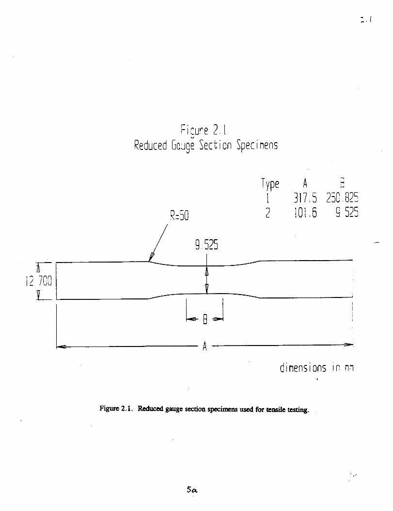
Specimens with a reduced gauge section were used to determine the tensile
strength. Two specimens with gauge lengths of 10 mm and 200 mm and a transition
radius of 2 inches were used to determine the volume dependence of the tensile strength
as shown in Figure 2.1. This radius has been shown to be sufficient to cause failures,
predominantly in the gauge section, for this type of composite [Jansson et al, 1991].
' i
m ,r IC.ure2
ReducedGeugeSect
!
onSpecinens
12.7OOL
Type12
A3175lOl 5
250.825o525,_J
dimensionsinnn
Figure 2.1. Reduced gauge section specimens used for tensile testing.
5OL
./
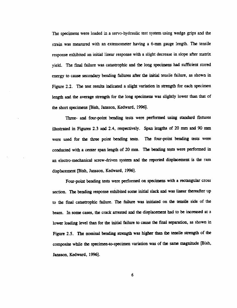
The specimens were loaded in a servo-hydraulic test system using wedge grips and the
strain was measured with an extensometer having a 6-ram gauge length. The tensile
response exhibited an initial linear response with a slight decrease in slope after mau'ix
yield. The final failure was catastrophic and the long Specimens had sufficient stored
energy to cause secondary bending failures after the initial tensile failure, as shown in
Figure 2.2. The test results indicated a slight variation in strength for each specimen
length and the average strength for the long specimens was slightly lower than that of
the short specimens [Bish, Jansson, Kedward, 1996].
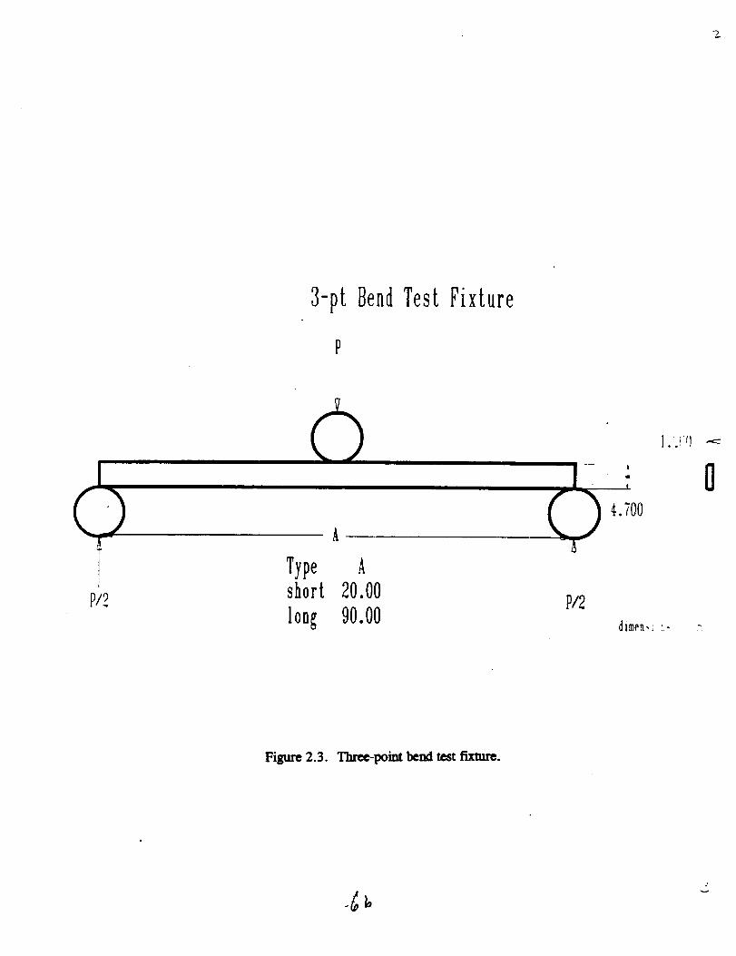
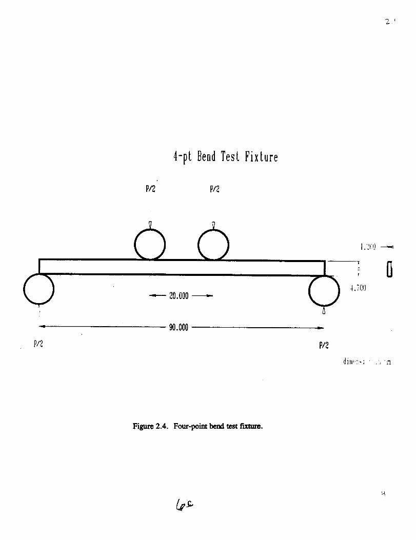
Three- and four-point bending tests were performed using standard fixtures
illustrated in Figures 2.3 and 2.4, respectively.
were used for the three point bending tests.
conducted with a center span length of 20 ram.
Span lengths of 20 mm and 90 mm
The four-point bending tests were
The bending tests were performed in
an electro-mechanical screw-driven system and the reported displacement is the ram
displacemem [Bish, Jansson, Kedward, 1996].
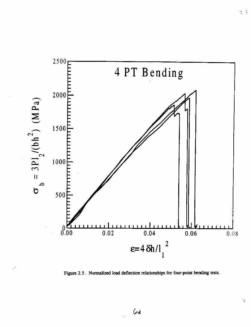
Four-point bending tests were performed on specimens with a rectangular cross
section. The bending response exhibited some initial slack and was linear thereafter up
to the final catastrophic failure. The failure was initiated on the tensile side of the
beam. In some cases, the crack arrested and the displacement had to be increased at a
lower loading level than for the initial failure to cause the final separation, as shown in
Figure 2.5. The nominal bending strength was higher than the tensile strength of the
composite while the specimen-to-specimen variation was of the same magnitude [Bish,
Jansson, Kedward, 1996].

2000
1500
m
mm
m
mm
m
m
m
m
SCS6/Ti 15-3 Tension
Short
Long
1000
t_
500
0.2 0.4 0.6 0.8 1.0
Figure 2.2. Longitudinal tensile responses.
Z
3-pt BendTest Fixture
P
P/2
A
Type Ashort 20.00
long 90.00P/2
I ,!iq
4,700
dimen,_ '-
0
Figure 2.3. Threc-poim bend test fixing.
4-pt BendTest Fixture
P/2 P/2
20.000 ----
'1
4.TOni
0
9
P/2
90.000
dira,'::- ; "
Figure 2.4. Four-point bctzl test fixture.
¢",1
d_
¢",1
¢,e3
II
t)
25O0
2000
1500
1000
500
m
m
m
lid
m
m
m
mmm
0 0.02
4 PT Bending
/
0.04
2_4_/1
1
/
I ,I F I
0.06III11 I I
0.08
Figure 2.5. Normalized load deflection relationships for four-point bending tests.
(pot
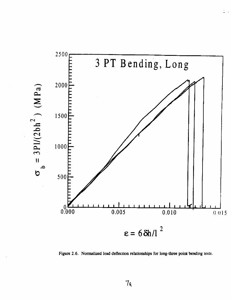
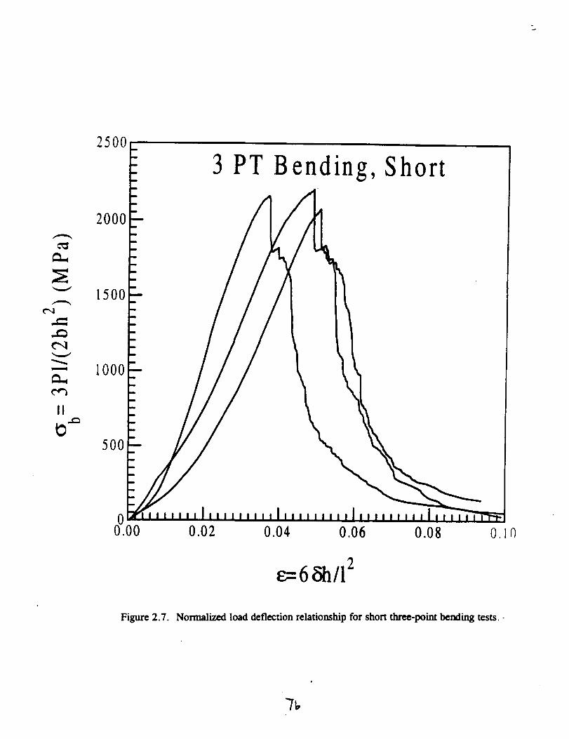
Three-point bending tests were performed on rectangular beams with two
different lengths. The response of the long beams were linear up to a catastrophic
failure with a load drop to zero load. The long beams were more flexible and had
sufficient stored energy to drive the fracture to a full separation as shown in Figure
2.6. The response for the short beams was more stable and the initial failure was
followed by controlled separation under decreasing load after the initial load drop, as
seen in Figure 2.7. The strength in shorter three-point bending specimens was higher
than for longer three-poim bending specimens. The strength in the three-point bending
tests was also higher than in four-point bending tests. The sample-to-sample variation
was of the same order as in the previous tests [Bish, Jansson, Kedward, 1996].
To assess the flaw sensitivity of the material, tests using double-edged notched
specimens were performed. The notches were cut by using a diamond blade saw with a
thickness of 0.2 mm. The specimen width was 8 mm and the ratio of notch length to
specimen width was 0.15, as illustrated in Figure 2.8. The results show that the
nominal stress, in the ligament between the two notches, was slightly lower than the
tensile strength of the short specimens. This indicates a notch weakening. The
fracture toughness was approximately KI -- 55 MPax/m [Bish, Jansson, Kedward,
1996]. This result compares favorably with the simple model by Kelly and Tyson
[1965] in which it is assumed that the toughness is given by the plastic dissipation in
the matrix. This model predicts a toughness of 50 MPa_/m. Another series of notch
tests were completed using various crack length to specimen width ratios. The results
t"q
m
II
t_
3 PT B ending, Long
00.000 0.005 0.010
f#
I_ L i d I I
2e= 68h/1
Figure 2.6. Normalized load deflection relationships for long-three point bending tests.
7_
t"q
¢-,4
m
II
25°°I 3 PT B ending, Short
2000
1500
1000
5OO
C)0 0.02 0.04 0.06 0.08 0.10
e,r. o _1,'12
Figure 2.7. Normalized load deflection relationship for short three-point bending tests.-

Double Edged\oLc,h SDec,inletl
101.600
-I 12.700
_--1.000
dimensions In mm
Figure 2.8. Specimen used to assess fracture toughness for short cracks.
-'/¢..
of this series of tests will eventually be used in the creation of a predictive model
examining the effects of notches on the ultimate strength of this material.
The final test series performed on the MMC's was to determine the fiber
properties in the manufactured material. The fiber modulus for the SCS6 fibers has
been reported to be in the range of 360 to 400 GPa. The fiber strength is length
dependent and is usually given in terms of a mean strength and a Weibuli modulus. A
mean strength of 4.3 GPa and a Weibull modulus of 9.3 has been reported for pristine
fiber with a length of 50 nun [Bain et. al, 1985]. To determine the in situ fiber strength
for the present composite, 100 fibers were extracted from the composite by etching the
matrix away using a 49 percent HF solution. A few initially broken fibers were found
in the composite. The average strength for the extracted fibers was 3.65 GPa and the
Weibull modulus was 4.9, as shown in Figure 2.9, [Bish, Jansson, Kedward, 1996].
This indicates that a substantial degradation occurs during the fabrication of the
composite.
2.2 Ultimate Strength and Elongation of PMC Systems
The second section of this study focuses on PMCs. The experimental research
in this section deals with creating an effective grip, so that the strength of composite
bars can be accurately determined. Traditional gripping mechanisms have proven
unsatisfactory in determining the tensile strength of composite rebars due to the
induced stress concentrations near the end of the grips which initiate a premature
8

J
e_o
o
0.5
0.0
-0.5
-I.0
-1.5
-20
-'2.5
3.2 3.3 3.4 3.5 3.6 3.7 3 S
Log(o) (M Pa)
Figure 2.9. Weibull plot of the strength of pristine fibers and fibers extracted from the
composite.
_A
failure. In this project, two types of clamping mechanisms were examined
experimentally in order to solve this problem. The first method is the clamp, in which
the rebar is held between four blocks fastened together by bolts. The second method is
the end wrap in which the rebar is wrapped with another material, usually with a
higher strain to failure than the rebar that is used to protect the test specimen.
The use of clamp grips and end wraps was examined as a means of alleviating
the increasing strain in the rebar adjacent to the bar/grip interface and the stress
concentration near the end of the clamp grips. The strain in the bar increased with
increasing radius with the maximum strain at the outer radius of the bar, but the strain
profile smoothed out as the distance from the grip end increased [Malvar, Bish, 1995].
These problems occurred in the clamp grip, four aluminum blocks bolted together with
a specified level of lateral pressure, and in standard grips, ASTM tab adapters, even
though an increase in strength was noted with the use of the clamp grips. The
predominant failure mode in the clamp grips was still caused by the high strain level at
the rebar/grip interface. By wrapping the bars with a material capable of handling high
elongations, this problem can be alleviated. Wrapping the bars with more layers of E-
glass was insufficient because, although the high strain levels had been removed from
the rebar, the strain level was still present in the wrap which fails causing failure of the
bar. Addition of a different material that can withstand higher strain levels should
solve this problem, provided the material is capable of high enough elongation. The
effects on the strain distribution caused by the addition of both stiff and flexible wraps
is illustrated by the f'mite element results presented in Figure 2. I0. In this figure, the
9

! .S
3.S
2.0
-4m I
--0"2
'-dr-.$
-'N-'4
"II--S
--'--end
I ,6
l_i_ure 2. lOc. Rad_ str_n disu_bution
sr_Y wntp
3.0
'll
O.8
0.0
,i i
I...e-1"4J--_t
, -=d_$
.,.,N--4
-41--0
0 m 4O
r
g
8Mm nmy,ul8 _ JMmuu
FiJum 2. lOd. _ smdn dislribud_
flexJl_e q
Figure 2.10. Finite element results for the radial strain distribution near the end of the
grip with and without end wraps.
_e
axial strain is plotted against the distance from the bar center for the first five (1-5)
layers of elements below the grips.
The majority of the current work on these types of gripping mechanisms
focuses on small diameter rods from 3.2 mm [Holte, Dolan and Schmidt, 1993] to 8
mm [Sippel, 1992], and [Iyer, Anigol, 1991]. This diameter is considerably smaller
than the 19 nun (.75 in) standard rebar examined in this study. The increase in size
causes premature rupture in the outer layers of the specimens creating an apparent size
effect due to the increased shear lag in the larger specimens.
Different kinds of PMC rebar were examined in the course of this study. A
hybrid, carbon/E-glass bar, and two kinds of E-glass bars which from previous work
have been shown to be well behaved. The hybrid bars consisted of an E-glass core
surrounded by an outer layer of carbon and E-glass at an angle. The hybrid bars were
tested using various end wraps, a carbon acrylic composite, soft copper tubing,
fiberglass, and various epoxies in an attempt to add more compliance to the system by
increasing the elongation near the bar/grip bar interface. The tests were showing
sporadic results, not due to the methods, but because of the bars. Close examination of
the bars, especially the failed specimens, showed extensive manufacturing variability in
the rebar. These imperfections included distortion of the rebar and inconsistent
thickness of the outer wrapping. These flaws caused premature failure of the bars.
The distorted rebar created significant bending effects in the tensile tests. Although
this effect is small, when combined with other flaws, the distortion of the rebar could
10
cause premature failure. The inconsistent outer wrap initiated failure due to the already
high strain levels at this critical location.
Of the two kinds of E-glass bars tested, both were at least 45 % fiber volume in
a polyester or vinylester matrix. The difference in the bars was primarily in their outer
surfaces; one had an outer layer of matrix material for protection while the other had a
sanded exterior with protruding deformations. The exterior one-eight-inch outer
coatings on the rebar are used to increase fiber protection and, in the case of the
protruding deformations, improve the pullout characteristics from concrete. These bars
underwent three test series. In these tests, the specimens had a diameter of
approximately 0.75 inches and were 42 inches long with a large clear spacing between
grips where two linear voltage displacement transducer(LVDT) with a gauge length of
12 inches were attached. The first series of tests served as a baseline. These tests
followed ASTM D3916. The next series of tests used a clamp grip tightened directly
onto the rebar. The final test used a clamp grip and the rebar was further protected by
a wrapping the ends with additional composite material. A substantial increase in the
measured strength was found by using both the clamp and the end wrap. In this
configuration, unlike the others, the failure was outside the grip, along the entire rebar,
and the measured strength was expected to be the highest attainable for these bars, as
reported in Table 2.1 [Malvar, Bish, 1995].
11

Table2.1. Effectof GripType on Measured Mechanical Properties
Bar
Type
Grip Tests Modulus of
Type Elasticity
GPa (ksi)
A ASTM 5
D3916
A Clamp 3
A Clamp 4+
Wrap 1
A Clamp 4+
Wrap 2
C ASTM 5
D3916
C Clamp 3
C Clamp 3+
Wrap 2
46.5 (6740) + 1.3 %
49.3 (7155) + 9.0%
47.8 (6930) ± 6.6%
47.4 (6880) + 2.4%
50.4 (7315) :t: 3.0%
Ultimate Stress
MPa (ksi)
598 (86.7) ±
2.2%
617 (89.5) ±
2.7%
680 (98.6)±
6.7%
648 (93.9) ±
3.2%
561 (81.4) +5.1%
710 (103.0) ±5.1%
Ultimate
Strain
0.0141 ± 3.4%
0.0153 + 4.0%
0.0157 ± 9.1%
0.0123 + 6.5%
768 (111.3) +5.1%
0.0186 ±
21.2%
An extensive investigation on how resin properties affect impact strength was
reported by Palmer [1981]. The same fiber, Thornel 300, together with 23 different
resins, was used in the investigation. Longitudinal tensile strengths and strains to
12
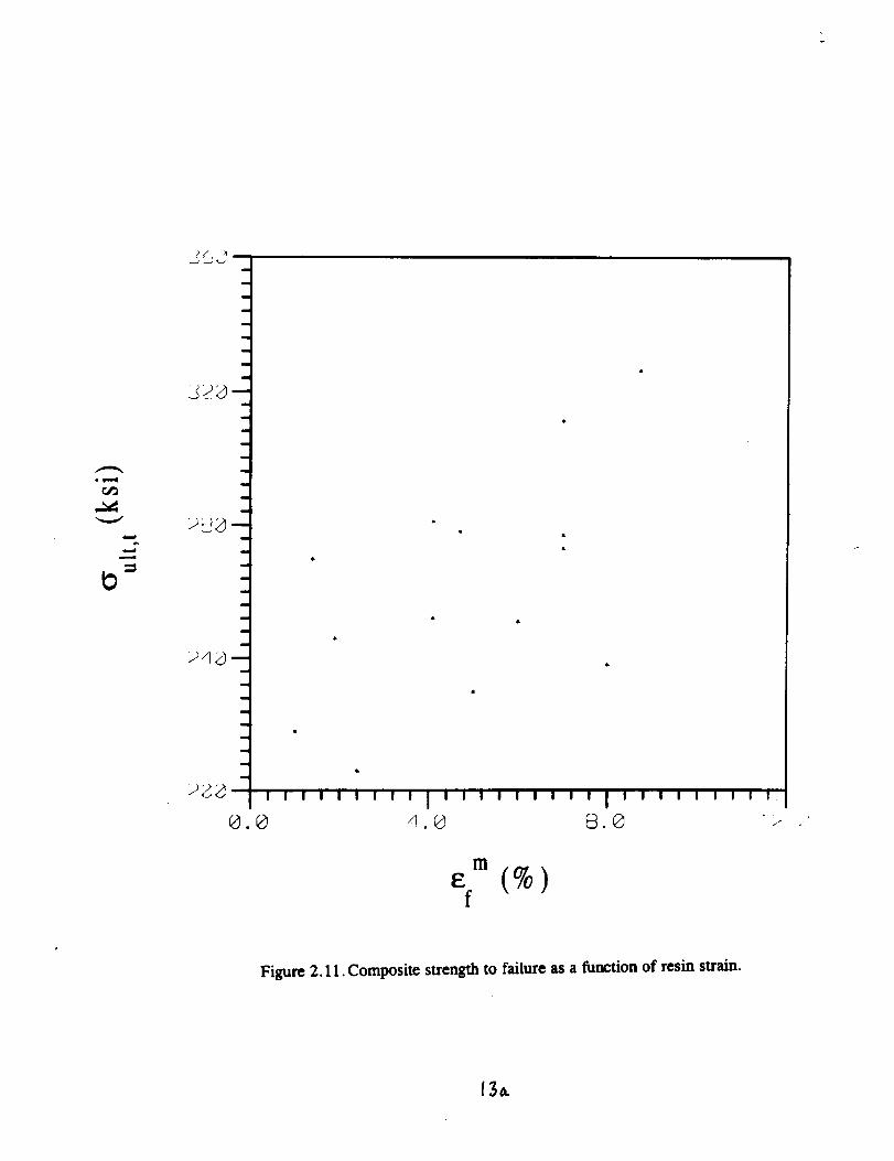
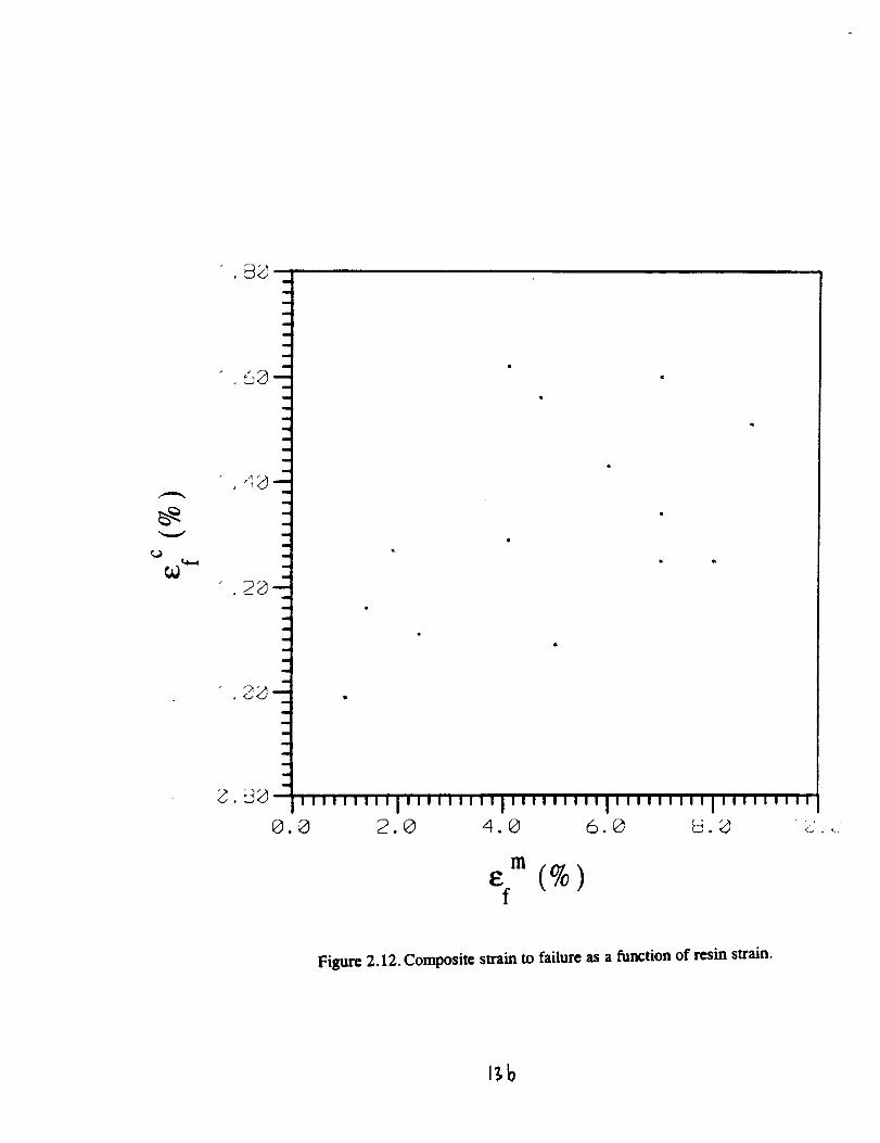
failure aregiven for thedifferentunidirectionalsystemsin the report. It wasshown
that the composite strength increases with resin modulus. A closer examination shows
that the increase is greater than what can be expected from the rule of mixtures and the
strengthening must be caused by an interaction between fitmr and matrix. The data have
been used to plot the composite strength versus resin strain to failure in Figure 2.11
and composite strain to failure versus resin strain to failure in Figure 2.12. These two
graphs show that the composite strength and strain to failure increases with matrix
strain to failure. It can be expected that a matrix with a higher strain to failure has a
higher toughness than a matrix with a lower strain to failure. Sufficient data for
strength modeling with the clustering models as given in Section 3 are not available.
However, the models predict that the critical defect size increases with matrix
toughness and this would cause an increase in composite strength as seen in this study.
13
o_
m
E (%)f
Figure 2.11. Composite strength to failure as a function of resin strain.
¢.2
m
i
!
I
!
q
i
i
5g'-!
m
,am
m
!
w
,Igm
I
a
m
I
i
I
i
I
I
m
i
m
m
m (%)f
Figure 2.12. Composite strain to failure as a function of resin strain.
J_b
3.0 THEORETICAL DEVELOPMENT OF STRENGTH AND DUCTILITY
This section describes analytical models that have been developed to assess the
strength and ductility of unidirectional composites. Many large components made of
composite materials do not exhibit the strength expected of specimen data that is
especially critical for large civil structures. This can be attributed to a volume
dependence of the composite material's strength, introduction of unknown defects
during the manufacturing of larger complex components, unexpected residual stresses,
or stress concentrations. A volume dependence of the tensile strength has been
observed for PMCs. Bullock [1974] found that this variation could be represented by a
two-parameter distribution (Weibull [1939]). Later, it was observed by Whitney and
Knight [1980], who had access to more experimental data, that the two-parameter
distribution was not sufficient to model the strength. For a brittle-brittle composite
system, Jansson and Leckie [1992] observed a substantial difference between the tensile
and bending strengths for different flexurai modes. This large difference in strength
was attributed to the formation of a macroscopic defect requiring a number of clustered
fiber breaks.
The fiber strength is frequently represented by a two-parameter Weibull
distribution that is based on the weakest link assumption. Unidirectional fiber-
reinforced composites usually exhibit a lower volume dependence in strength than the
individual fibers. In this type of composite, the fibers are parallel and the weakest link
14

conceptfor the individualfibers is not likely to apply because a break in an individual
fiber causes a stress redistribution and the load is carried by the remaining unbroken
fibers. This feature was addressed in the analysis of a dry fiber bundle by Daniels
[1945]. For a large bundle, many fibers are engaged inthe failure and the strength is
deterministic with an effective bundle length that is equal to the length of the
composite. The concept of a fiber bundle was later modified to include the contribution
to the load-carrying capacity from sliding between matrix and broken fibers, cf., Sutcu
[1989], Thouless and Evans [1988] and Curtin [19931. The load transfer to the
surrounding matrix causes the effective fiber bundle length to be shorter than the gauge
length and has been related to the stress recovery length of a broken fiber, cf., Phoenix
[19931, Curtin [19931 and Jansson and Kedward [1996]. This type of failure, where
the load carried by a broken fiber is redistributed equally between the still-intact fibers,
is commonly denoted as global load sharing.
Another extreme of behavior was suggested by Zweben and Rosen [1970]. In
their model, it is assumed that a critical defect is formed when a secondary break
adjacent to a previously broken fiber occurs and the load-carrying capacity of the
composite is lost. This leads to a Weibull modulus for the composite that is
approximately twice the value of the fiber modulus. This type of failure is denoted as
local load sharing.
Coleman [1958] showed that a fiber bundle with a finite number of fibers has a
variability in strength. This variability decreases as the number of fibers in the bundle
increases. This variation in the strength of finite fiber bundles was used by Gticer and
15
Gurland[1962]. They assumed that the composite consists of layers in series and each
layer consists of a number of fiber bundles. A layer loses its load-carrying capacity
when one bundle in the layer breaks and a weakest-link system is formed in the layers
of the composite material. These models have been refined and references are given in
Phoenix [1993]. The actual size of the fiber bundle is frequently determined by fitting
the model to composite strenth data. This implies that such models cannot be used to
study how the matrix and interface influences the composite strength.
In this section, a simple model tbr a composite that exhibits perfect fiber
fragmentation is presented. It is shown that the strength and ductility predictions for
this model compare favorably to other expressions available in the literature, such as
when compared to a detailed numerical analysis of the same problem by Neumeister
[1993]. This type of fragmentation model gives an indication of the achievable strength
and ductility for a composite. However, many composites fail before the fragmentation
strength is reached. This is caused by the clustering of fiber breaks into a large defect
that triggers a global failure. The fragmentation model is used together with a statistical
model for the clustering of fiber breaks to determine the strength for different
composite systems. Some new aspects of the local load-sharing model are also
discussed in relation to clustering of fiber breaks.
16
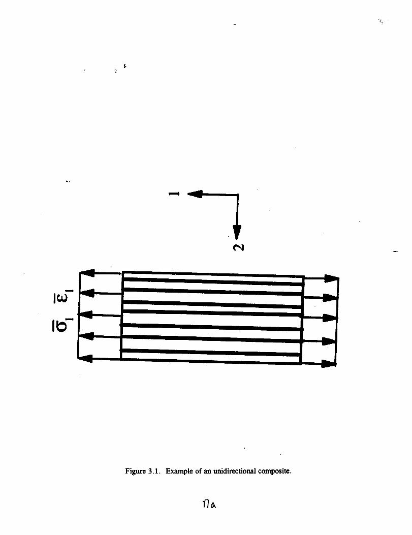
3.1 Model for Fiber Fragmentation
Consider the unidirectional composite that is depicted in Figure 3.1. Following
Jansson and Kedward [1996],a the average stress in the longitudinal direction is given
as
_, = fox( +(1 - f)_' (3.1)
where f is the fiber volume fraction and the average stresses for the two phases are
given by
i = _ dv (3.2)Yct _;_
where vet is the volume of each phase. Assume that the composite is subjected to a
strain field with an average strain _t in the longitudinal direction. Furthermore, the
strain field is such that no average transverse stresses develop. For a composite with a
brittle matrix, cracking occurs transverse to the fiber direction before the ultimate
strength is reached, causing _' = 0 at failure. In the case of a PMC, the matrix
contribution to the longitudinal stress could be considered to be insignificant because of
the relatively low stiffness of the matrix. For an MMC with a ductile matrix, the
matrix can carry a significant load and the phase average can, to a good approximation,
be assumed to be given by the uniaxial stress-strain relation for the matrix as
17
$
Figure 3.1. Example of an unidirectional composite.
I_
a_-" = a'(g, ) (3.3)
The strength of brittle fibers is often expressed in statistical terms. For a simple
two-parameter Weibull distribution [Weibull, 1939], the survival probability for a
single fiber of length I is given as
(3.4)
where o / is the stress in the fiber, 10, o0 and m are constants governing the strength
distribution of the fiber. A high value of the Weibull modulus, m, indicates a low
variability in strength. If a single fiber could be subjected to a stress o f throughout the
whole length, then the number of breaks in the fiber would be
(3.5)
For a fragmented fiber in a composite with a surrounding matrix, stress
recovery occurs at the fiber breaks and the stress gradually builds away from the break
to the far field value. This causes the number of actual breaks for a fiber in a composite
to be lower than what is given by Equation 3.5. Assuming that the breaks are well
separated and that the linear stress recovery model by Kelly and Tyson [1965] applies,
18
the stressdistributiongiven in Figure 3.2 would be present in a fiber. The recovery
length is given as
dcr f1R= _ (3.6)
where x, is a constant sliding resistance at the fiber matrix interface and d is the fiber
diameter. In reality, the stress recovery is quite complex with a sliding zone and an
elastic recovery region. Experimental data are frequently evaluated in terms of this
simple model and the reported sliding resistance only represents an average value in a
simplified model of stress recovery. Differentiation of Equation 3.5 with respect to
stress gives
dn= lm(c_ f )'-_ da / (3.7)10(<_0)"
For the fiber stress distribution given in Figure 3.2, new breaks can only occur in the
regions of the fibers that can be subjected to a stress increase, which are given by
portions of the fiber that have a constant stress distribution. Hence, the effective length
in which new fiber breaks can occur is
t = L - 2ntR (3.8)
19
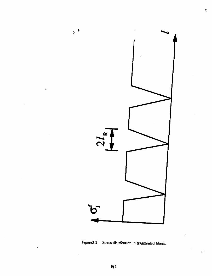
$B
Figure3.2. Stress distribution in fragmented fibers.
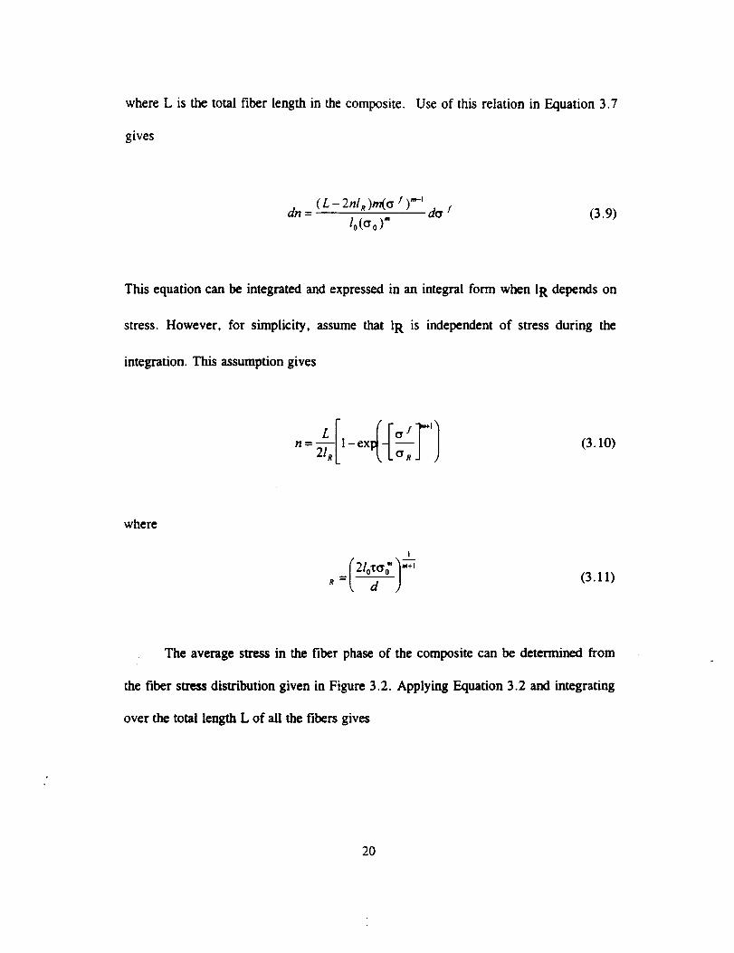
where L is the total fiber length in the composite. Use of this relation in Equation 3.7
gives
dn = ( L - 2hi R)m(o f )_'-' do / (3.9)10(o0)"
This equation can be integrated and expressed in an integral form when 1R depends on
stress. However, for simplicity, assume that 1R is independent of stress during the
integration. This assumption gives
n L o ! ' (3.10)
where
(3.11)
The average stress in the fiber phase of the composite can be determined from
the fiber stress distribution given in Figure 3.2. Applying Equation 3.2 and integrating
over the total length L of all the fibers gives
20
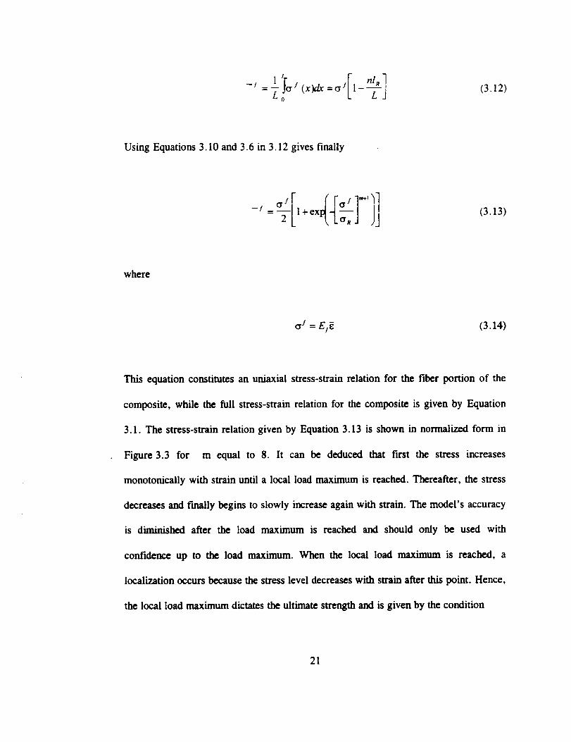
I!o " , [ (3.12)
Using Equations 3. I0 and 3.6 in 3.12 gives finally
(3.13)
where
o / = Ej[ (3.14)
This equation constitutes an uniaxial stress-strain relation for the fiber portion of the
composite, while the full stress-strain relation for the composite is given by Equation
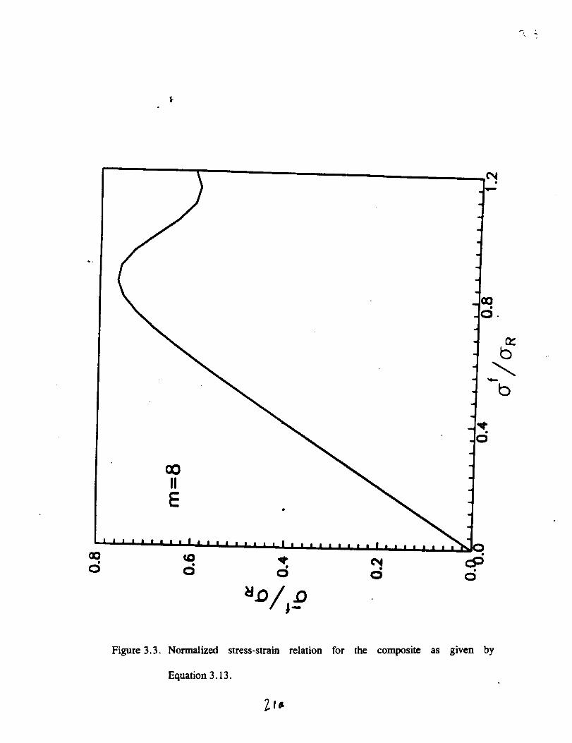
3. I. The stress-strain relation given by Equation 3.13 is shown in normalized form in
Figure 3.3 for m equal to 8. It can be deduced that first the stress increases
monotonically with strain until a local load maximum is reached. Thereafter, the stress
decreases and f'mafly begins to slowly increase again with strain. The model's accuracy
is diminished after the load maximum is reached and should only be used with
confidence up to the load maximum. When the local load maximtun is reached, a
localization occurs because the stress level decreases with strain after this point. Hence,
the local load maximum dictates the ultimate strength and is given by the condition
21
IIE
Figure3.3. Normalized stress-strain relation for the composite as given by
Equation 3.13.
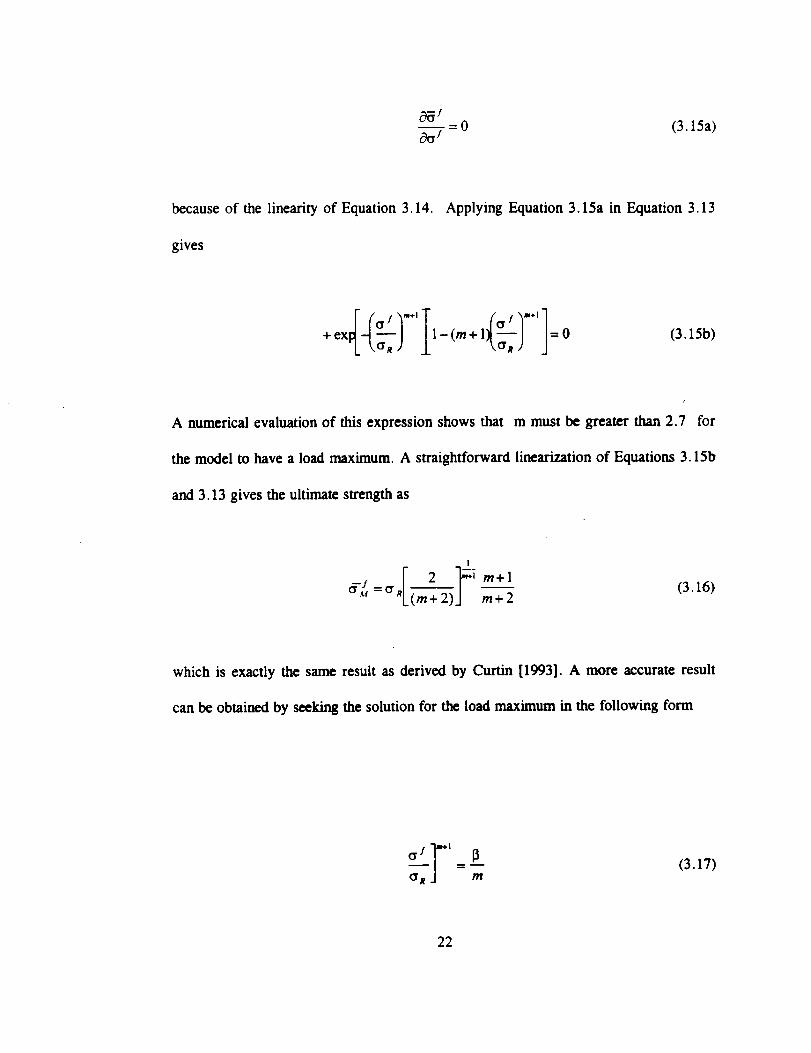
= 0 (3.15a)c_ j
because of the linearity of Equation 3.14. Applying Equation 3.15a in Equation 3.13
gives
+ 1 o-0 (3.15b)
A numerical evaluation of this expression shows that m must be greater than 2.7 for
the model to have a load maximum. A straightforward linearization of Equations 3.15b
and 3.13 gives the ultimate strength as
2 -]g_m+l (3.16)
which is exactly the same result as derived by Curtin [1993]. A more accurate result
can be obtained by seeking the solution for the load maximum in the following form
(3.17)
22

where 13has to be determined.InsertingEquation3.17
collectingtermsof differentorderin l/m gives
into Equation 3.15b and
0=(2_13)+13(13 -2) 132(I3-3 ) 133(13-4)m 2m _ t- 2m 3 ..... (3.18)
By choosing 13equal to 2, the condition for the load maximum is satisfied by the two
leading terms of the series expansion and is also asymptotically correct for large values
of m. Use of this result in Equation 3.13 gives the following expression for the load
maximum
(3.19)
The strength predictions for this model are compared with the numerical solution by
Neumeister [1993] in Figure 3.4. This model also compares favorably with the detailed
numerical simulation of the expressions given by Curtin, [1993] and Phoenix [19931
and can be used with confidence in the subsequent strength models.
One aspect that has been overlooked in the discussions of composite strength is
the strain at which the load maximum occurs. The composite average swain is related
to the fiber stress far away from the break by Equation 3.14. The average strain at the
load maximum can thus be determined by using this relation and inserting the fiber
stress at the load maximum in Equation 3.14, to give
23
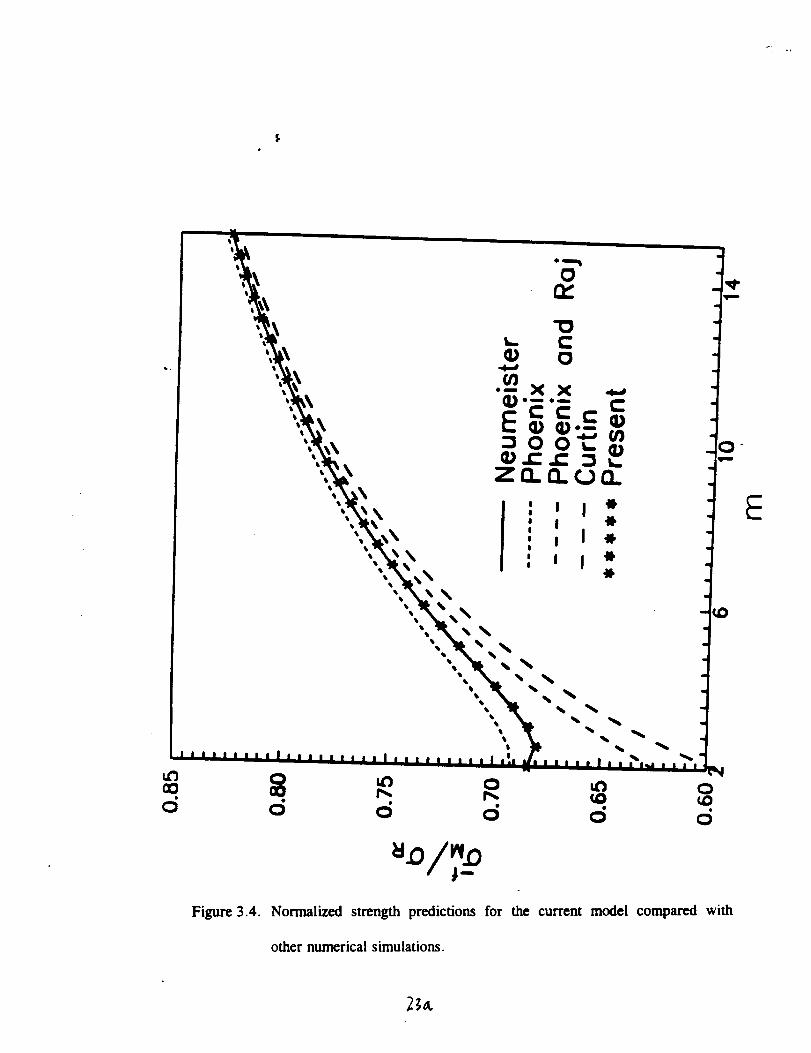
Figure 3.4. Normalized strength predictions for the current model compared with
other numerical simulations.
2_0t
[
(3.20)
The strain at the load maximum is shown in normalized form in Figure 3.5
together with the numerical simulations by Neumeister [1993] and the other models. It
can be concluded that all the closed-form solutions underestimate the strain at the load
maximum. Of these examples, the present model has the lowest discrepancy. The lower
strain prediction occurs because the possibility of an overlap of the slip regions has
been ignored in this model.
The model given by Equation 3.14 is equivalent to the assumption that the load-
carrying capacity of the composite is given by a fiber bundle of length 21R which has a
frictional sliding contribution from the pullout of the broken fibers with an effective
sliding length of 1R/2.
This type of fiber-fragmentation model should be viewed as an indicator of the
maximum achievable, longitudinal strength and strain at the load maximum of a
composite. Many different failure events can occur before this strength is reached.
Some of these failures will be discussed in subsequent paragraphs.
24

E
Figure 3.5. Normalized strain at the load maximum compared with other numerical
simulations.
24 _.
3.2 Failure by a Mode I Crack
A global failure of a composite occurs when a macroscopic defect is formed.
This defect can be characterized as one of a number of different global failure types
which can occur in a composite before the perfect fragmentation strength is reached.
For some composites, experiments indicate that the fracture planes are perpendicular to
the fibers and the loading direction. This suggests that the macroscopic failure for the
present composite is given by the formation of a mode I crack [Bish, Jansson and
Kedward, 1996]. It will be assumed that the critical crack is formed when a
sufficiently large local fiber bundle has reached its load maximum. The crack opening
is then exerted on by the fiber portion of the composite stress and the matrix still
bridges the crack because of its higher ductility. The diameter of the fiber bundle that
fails has to be sufficiently large in order to be able to drive the growth of defects. For
linear elastic fracture mechanics, the radius of the bundle is related to the toughness as
(3.21)
where it has been assumed that the broken fibers cause an opening of the crack while
the matrix still bridges the crack. It is further assumed that only fiber breaks within one
transfer length, Ir, from the crack face affect the opening mode of the crack. This
implies that the volume of the critical defect, or the local fiber bundle is
25
v_ = 2lRrta 2 - 2=f4 o._(3.22a,b)
The total length of fibers in this volume is given by the relation
7td 2
Iv 4 - f2naZln (3.23)
The average number of fiber breaks in one bundle can the be determined by use of
L = ls/and Equations 3.11 and 3.23 in Equation 3.10 gives
(3.24)
and the number of breaks at the load maximum is
I
-..,r,,,,,n= d t,410oo'c) L(3.25)
Because of the statistical nature of the fiber breaks, the breaks will cluster in some
regions. This is a well-known phenomenon in statistics and the probability of finding
breaks inside v_, when the average numbers of breaks in vh is n, is given by a Poisson
distribution as
26
n tw
p(n = _) = e-" -- (3.26)
The fiber bundle is at the load maximum when this value is reached. However, it will
also have reached the load maximum if more breaks have occurred. This condition is
given by the cumulative Poisson distribution as
y(_,n)p(s > _) = (3.27)
r(_)
where y is the incomplete and F is the complete gamma function. Hence, the
probability that a fiber bundle has reached the load maximum and a critical defect is
formed, is given by this expression. This can occur at any location in the composite
and the survival probability of the composite can then be determined by using a
weakest-link approximation for the composite as
p =i-i(l_p_)=exp(_!y(K,n)dV)F(_.) _':' (3.28a, b)
where n is given by Equation 3.24, _ by Equation 3.25 and vb by Equation 3.22. The
result, Equation 3.28b is based on the assumption that p_ << , which is usually the
case.
27
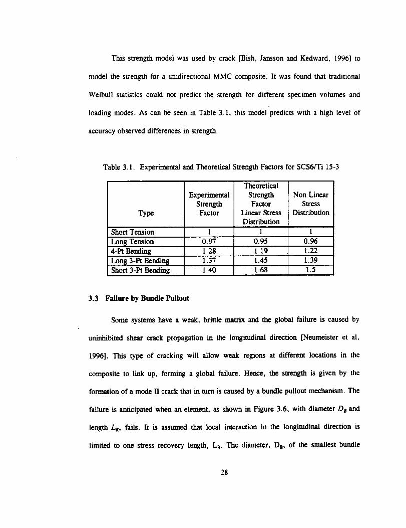
This strengthmodel was used by crack [Bish, Jansson and Kedward, 1996] to
model the strength for a unidirectional MMC composite. It was found that traditional
Weibull statistics could not predict the strength for different specimen volumes and
loading modes. As can be seen in Table 3.1, this model predicts with a high level of
accuracy observed differences in strength.
Table 3.1. Experimental and Theoretical Strength Factors for SCS6/Ti 15-3
Type
Short Tension
Long Tension
Experimental
StrengthFactor
1i
0.97
Theoretical
StrengthFactor
Linear Stress
Distribution
0.95
Non Linear
Stress
Distribution
0.96
4-Pt Bending 1.28 1.19 1.22
Long 3-Pt Bending 1.37 1.45 1.39
Short 3-Pt Bending 1.40 1.68 1.5
3.3 Failure by Bundle Pullout
Some systems have a weak, brittle matrix and the global failure is caused by
uninhibited shear crack propagation in the longitudinal direction [Neumeister et al,
1996]. This type of cracking will allow weak regions at different locations in the
composite to link up, forming a global failure. Hence, the strength is given by the
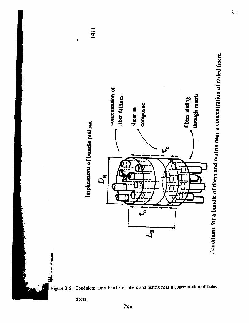
formation of a mode ITcrack that in turn is caused by a bundle pullout mechanism. The
failure is anticipated when an element, as shown in Figure 3.6, with diameter Da and
length LR, fails. It is assumed that local interaction in the longitudinal direction is
limited to one stress recovery length, LR. The diameter, Ds, of the smallest bundle
28
|
&
m
u
0
.g c0
o_
ofib
0rj
Conditions for a bundle of fibers and matrix near a concentration of failed
fibers.
element that can be pulled out is given by a balance of the interlaminar shear strength
Tc and interfacial sliding stress "_as
r_DnLRx_ = nB_dLnx , (3.29)
The use of this definition of the fiber volume fraction and Equation 3.6 give the
element volume as
nd3 (3.30)3V_ 16f2xi
The number of breaks in the fiber bundle can be determined by use of Equations 3.10
and 3.11 as
1 x c 1-exn = 2/\x,./ 21oo'o'_,
(3.31)
and the number of breaks at the load maximum is given by
(3.32)
29
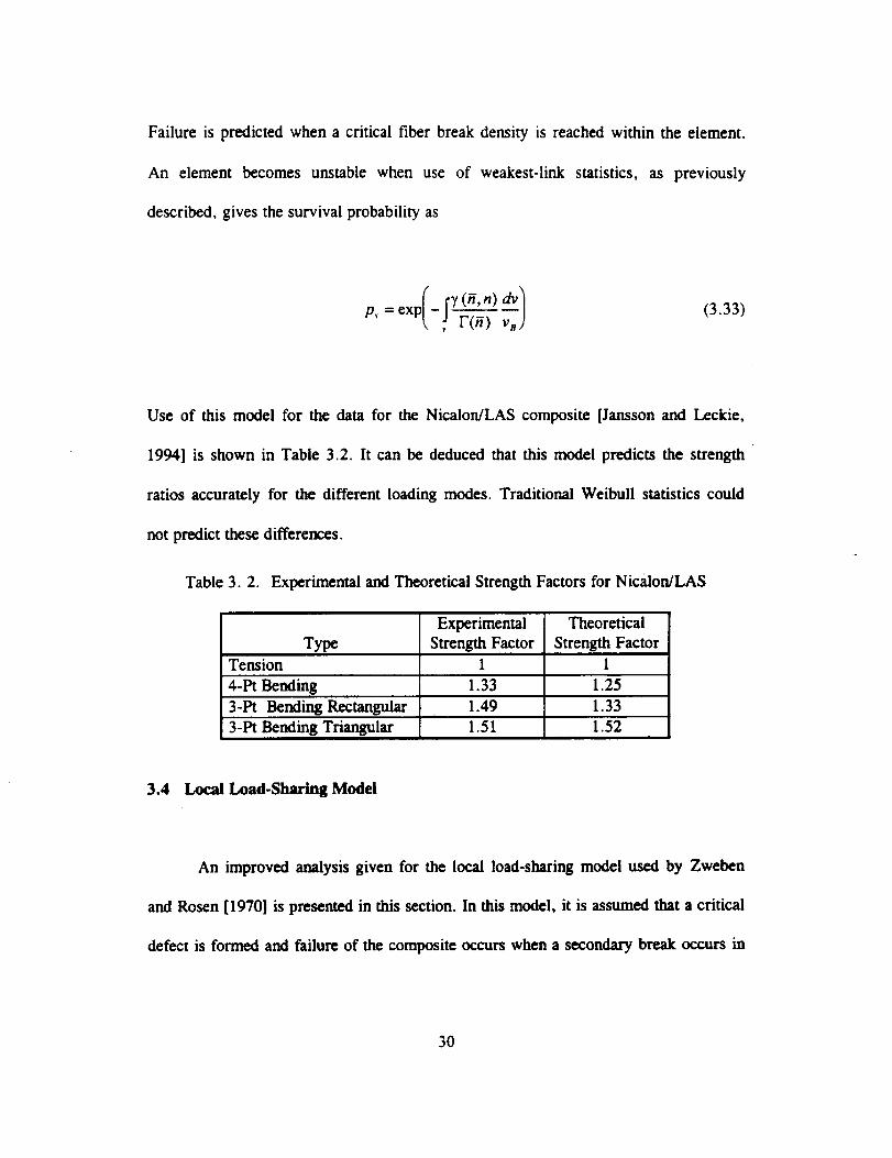
Failure is predicted when a critical fiber break density is reached within the element.
An element becomes unstable when use of weakest-link statistics, as previously
described, gives the survival probability as
(r3'(_,n) ,_
P, = exp[ - J- F--_(3.33)
Use of this model for the data for the Nicalon/LAS composite [Jansson and Leckie,
1994] is shown in Table 3.2. It can be deduced that this model predicts the strength
ratios accurately for the different loading modes. Traditional Weibull statistics could
not predict these differences.
Table 3.2. Experimental and Theoretical Strength Factors for Nicalon/LAS
Experimental Theoretical
Type Strength Factor Strength Factor
Tension 1 1
4-Pt Bending 1.33 1.25
3-Pt Bending Rectangular 1.49 1.33
3-PtBending Triangular 1.51 1.52
3.4 Local Load-Sharing Model
An improved analysis given for the local load-sharing model used by Zweben
and Rosen [1970] is presented in this section. In this model, it is assumed that a critical
defect is formed and failure of the composite occurs when a secondary break occurs in
30
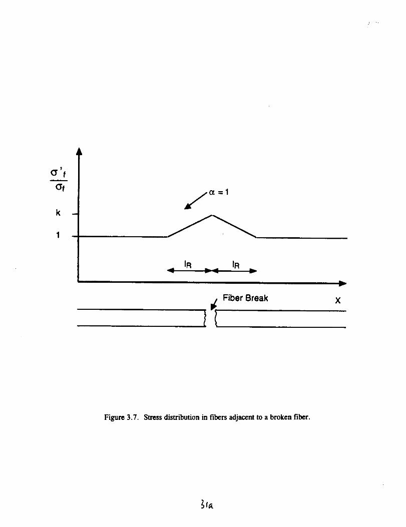
a neighboringfiber to a previouslybrokenfiber. The secondarybreak hasto occur
within onestressrecoverylengthfrom theinitially brokenfiber. Theinitial fiber break
causesa stressconcentration,depictedin Figure3.7, over a length21Rin the next
neighboringfibers.Theprobabilitythat thesegmentof length21_of anadjacentfiber
survivesto thestresslevelof experiencedbeforethefiberbreakis
.0 ex(/o k6o J )
(3.34)
and the probability that it survives the stress concentration caused by the fiber break is
/p I= -k,-',\ 6o }
(3.35)
where k is the highest stress concentration in the adjacent fibers and
1
k n,.¢.lot - (3.36)
for the present stress distribution as illustrated in Figure 3.7. For a constant stress
distribution over the segment andct = 1, the probability that an adjacent fiber survives
31
2
_'f
Of
k
IR IR
I I Fiber Break
h,r
X
Figure 3.7. Stress distribution in fibers adjacent to a broken fiber.
to the stress level experienced before the initial break or breaks because of the stress
concentration caused by the initial break is given by the conditional probability
-p7P] - (3.37)
1_/,/°
where pA = 1 - p A. The probability that all the 13neighboring fibers survive isf
O_p )o (p,'l= e?) (3.38)
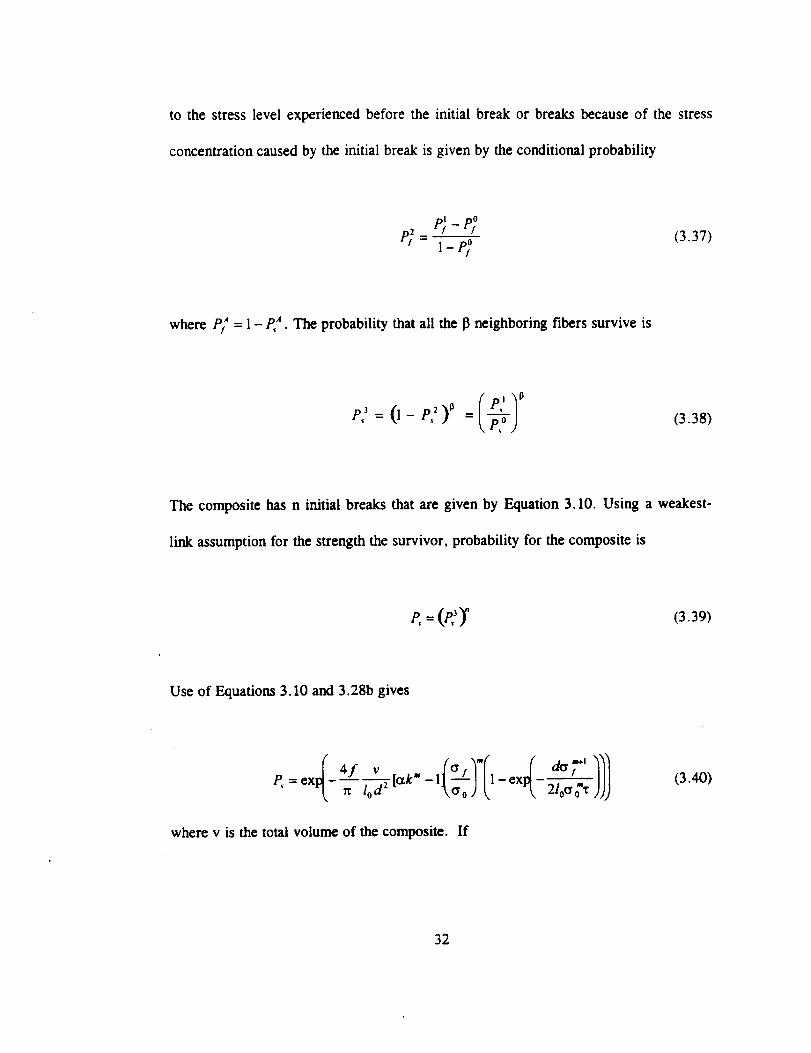
The composite has n initial breaks that are given by Equation 3.10. Using a weakest-
link assumption for the strength the survivor, probability for the composite is
P, -- (P_)" (3.39)
Use of Equations 3.10 and 3.28b gives
4f vP, = ex - [ctk" - 1 1- ex
rc 1odz
where v is the total volume of the composite. If
(3.40)
32
f--<<I210oo'Z
then
(3.41)
For a globally varying stress distribution, the survival probability has to be integrated
over the volume of the composite giving the relation
P,=ex - [_km - 1]' ,0" o T
(3.42)
This equation indicates that the Weibull modulus for the composite is 2m+ 1.
33
3.5 Failure by Clustering of Two Breaks
The critical defect in the local load-sharing model is given by two fiber breaks
in adjacent fibers within two stress recovery lengths LR. This failure can also be caused
by clustering of two breaks. The probability of clustering of two breaks in adjacent
fibers is given by Equation 3.28b by using
= 2 (3.43)
and
L = 41R (3.44)
The critical volume element is given by
rcdZ 1 rtd3crf
v° =2"2lR 4 f- 4fT (3.45)
to give
_p, = ex _ 1"(2)
(3.46)
34
A comparison between this model with global load sharing and other models
which utilize the concept of local load sharing is shown in Figure 3.8. In the local-load
sharing model, the redistribution of stress from a broken fiber is transferred only to the
neighboring fibers. Thus, the stress concentration due to the failure of a fiber is
confined to a localized area. An upper bound on the stress concentration is given by the
assumption that the load from the broken fiber is carried only by the surrounding
fibers, k is equal to 7/6. In reality, the load from the broken fiber is distributed over
more fibers and the stress concentration is lower. A sliding fiber-matrix interface and
matrix plasticity also reduce the stress concentration. A realistic number is k = 1.07. It
can be deduced from Figure 3.8 that it is more likely that a composite will fail from
clustering of two breaks than from the local stress concentration caused by a fiber
break on the adjacent fibers.
35

-,-" " Cluster model, GLS
LLS, c_..95 3 k= 1.02
: : : LLS, (x=.853 k-1.07
LLS, c_=1 k-- 1.167Cluster of two breaks
Theoretical strength
0.00 100.00 200.00 300.00 400.00 5t),_ ,)t)
3Specimen Volume (mm)
Figure 3.8. A comparison
sharing.
of models using the concepts of global and local load
_5"a,
4.0 STRESS REDISTRIBUTION IN COMPONENTS
Many components will be exposed to load and temperature variations for an
extended time. The temperature and loading could be such that the stresses in the
weaker and often softer phase of the composite, the matrix, relaxes. Some systems
have a weak bond between fiber and matrix and this relaxation can dramatically change
the matrix-dominated properties. Environmental effects, such a moisture, can also
affect the bond between matrix and fiber in some systems. Here, some results are
presented for an investigation on an MMC system for which the residual clamping
pressure between fiber and matrix has been relaxed by subjecting the composite to a
thermo-mechanical loading history.
4.1 Observed Mechanical Behavior.
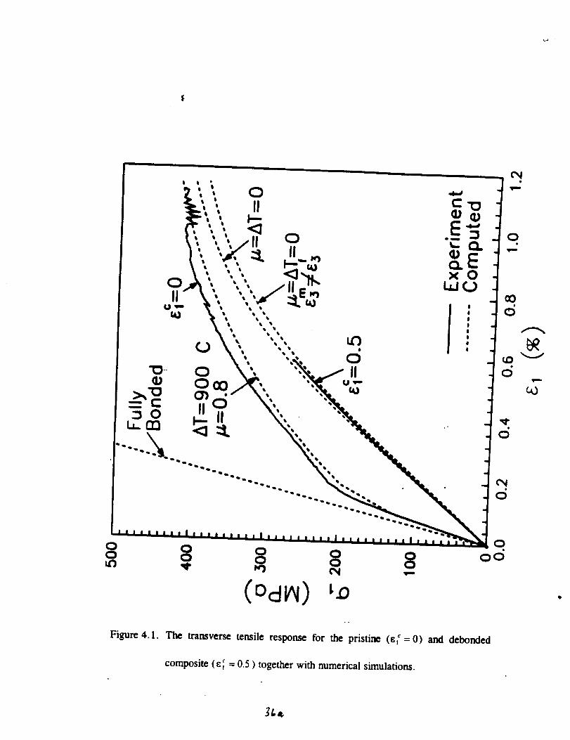
4.1.1 Transverse Tension. The transverse tensile response is shown in Figure
4.1 for the pristine (_=0) and debonded composite (c_=0.5) together with
numerical simulations. It was found by Gunawardena et ai., [1993] that the response of
the pristine composite was modeled well by including the residual stresses from a
fabrication temperature of 900oc and an interface that can only transfer compressive
normal stresses and has a friction coefficient of la = 0.8. It is interesting to note that
the initial linear response for the composite is slightly more compliant than that for a
36
qk • •
OII
O O O Oo o o 8 8 ooUl3 _1" Iq3 ¢N _-
Figure 4.1. The transverse tensile response for the pristine (sv_=0) and deb0nded
composite (c; = 03 ) together with numerical simulations.
3t._
compositewith a fully bondedinterface.After the initial linear response, a substantial
decrease occurs in the slope of the stress-strain curve and this is caused by debonding
at the fiber matrix interface. The computations also indicate that some localized
yielding occurs in the matrix at the initial portion of the debond. Finally, the interface
is fully debonded in the loading direction and the load-carrying capacity is dictated by
the matrix ligaments between the fibers. A simple estimate for the transverse limit
strength [Jansson et al, 1991] gives
2
<_rL- j_ A_._,.. (4.1)
where Afro is the matrix area fraction at the weakest plane and el,, is the limit strength
of the matrix. The strain to failure is approximately 40% of the matrix failure strain of
3.2%. This reduction in failure strain is caused by a concentration of strain in the
matrix ligaments between the fibers because they are subjected to a higher stress.
The response for the debonded composite, e_ =0.5, has a much more
compliant initial linear response compared to the pristine composite. The modulus is
only a third of the modulus for the pristine composite and is of the same magnitude as
was observed for the same composite after cyclic thermo-mechanical load [Jansson et
al., 1994]. It can be deduced that this response is modeled closely by assuming an
initially stress-free interface, AT=0. The calculated response after debond is insensitive
to the value of the coefficient of friction at the interface and quite insensitive to the
constraint in the longitudinal direction. The response for the case where the fiber and
37
matrix have the same longitudinal strain is only slightly stiffer than the response for the
case where the matrix is assumed to be fully decoupled from the fiber in the
longitudinal direction, c _' _ c f.
The failure strain in the tensile test for the debonded composite is 0.6%. The
specimen had previously accumulated a creep strain of 0.5%, giving a total strain of
1.1%. This total failure strain is very close to the observed failure strain for the
pristine composite, indicating that a constant strain criteria could be used as a failure
condition for this type of loading.
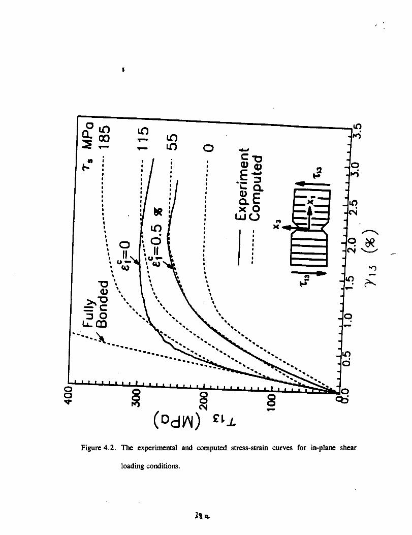
4.1.2 In Plane Shear. Shear tests have been performed with the fibers
orientated in the direction of the two notches as shown in Figure 4.2. It was shown by
Jansson et al. [1994] that the limit strength is dependent on the orientation of the fibers
for composites with weak interfaces in this type of test. The present loading subjects a
long portion along the fibers to constant conditions and is representative of loading that
occurs in practical applications. It has a lower limit strength than the case where the
fibers are oriented perpendicular to the notches. The experimental and computed stress-
strain curves are shown in Figure 4.2.
The response for the pristine composite has a initial linear response followed by
a gradual transition that reaches a limit condition with no increase in stress. A
comparison with the numerical simulations indicated that no sliding occurs initially at
the interface. This is followed by a response that corresponds to a sliding with a shear
stress of 185 MPa at the interface. The sliding stress thereafter gradually decreases
38
0 0
o _ o o c_,¢ 0 0
Figure 4.2. The experimental and computed stress-strain curves for in-plane shear
loading conditions.
Jr=,
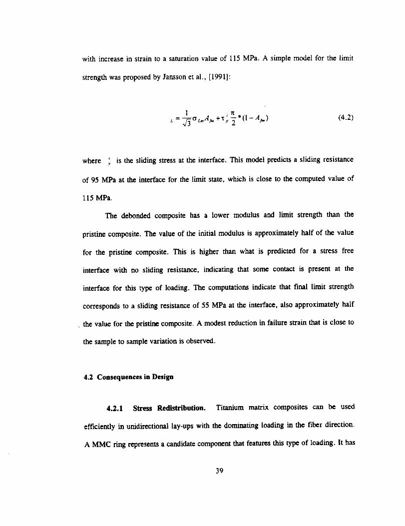
with increase in strain to a saturation value of 115 MPa. A simple model for the limit
strength was proposed by Jansson et al., [19911:
l + aT_
t.- v_°L.,A_,, x,-_-*(l-A_,) (4.2)
where '_ is the sliding stress at the interface. This model predicts a sliding resistance
of 95 MPa at the interface for the limit state, which is close to the computed value of
115 MPa.
The debonded composite has a lower modulus and limit strength than the
pristine composite. The value of the initial modulus is approximately half of the value
for the pristine composite. This is higher than what is predicted for a stress free
interface with no sliding resistance, indicating that some contact is present at the
interface for this type of loading. The computations indicate that final limit strength
corresponds to a sliding resistance of 55 MPa at the interface, also approximately half
the value for the pristine composite. A modest reduction in failure strain that is close to
the sample to sample variation is observed.
4.2 Consequences in Design
4.2.1 Stress Redistribution. Titanium matrix composites can be used
efficiently in unidirectional lay-ups with the dominating loading in the fiber direction.
A MMC ring represents a candidate component that features this type of loading. It has
39
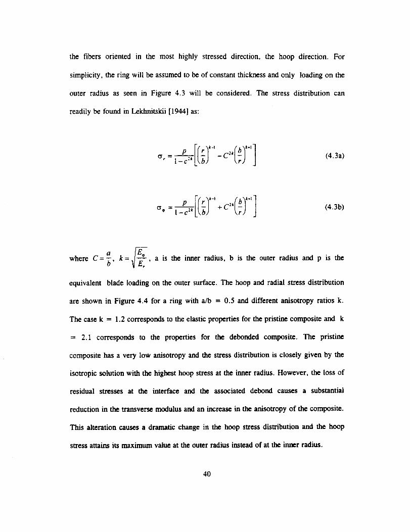
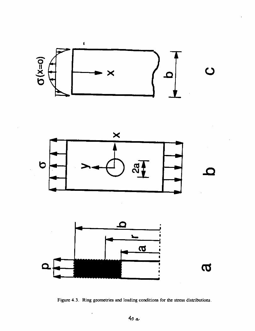
the fibers oriented in the mosthighly stresseddirection, the hoop direction. For
simplicity,thering will beassumedto beof constantthicknessandonly loadingon the
outer radius as seenin Figure4.3 will be considered.The stressdistribution can
readilybe foundinLekhnitskii[1944]as:
I- "*LGJ -c"[7) (4.3a)
a
where C= _, k = _--_-, a is the inner radius, b is the outer radius and pis the
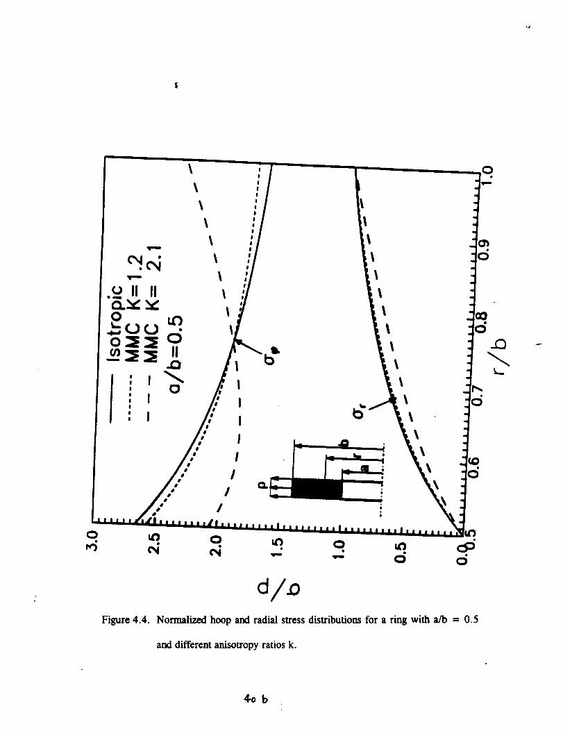
equivalent blade loading on the outer surface. The hoop and radial stress distribution
are shown in Figure 4.4 for a ring with a/b = 0.5 and different anisotropy ratios k.
The case k = 1.2 corresponds to the elastic properties for the pristine composite and k
= 2.1 corresponds to the properties for the debonded composite. The pristine
composite has a very low anisotropy and the stress distribution is closely given by the
isotropic solution with the highest hoop stress at the inner radius. However, the loss of
residual stresses at the interface and the associated debond causes a substantial
reduction in the transverse modulus and an increase in the anisotropy of the composite.
This alteration causes a dramatic change in the hoop stress distribution and the hoop
stress attains its maximum value at the outer radius instead of at the inner radius.
40
_I ¸ - Xv
X
Q.
I_. .O
!
!
I
|
I
|
Figure 4.3. Ring geometries and loading conditions for the stress distributions.
T""
.u II II
I
I
I
I
I
!
I
I
!0
I
I
//
I
I
I
I
Figure 4.4. Normalized hoop and radial stress distributions for a ring with afo - 0.5
and different anisotropy ratios k.
Cob
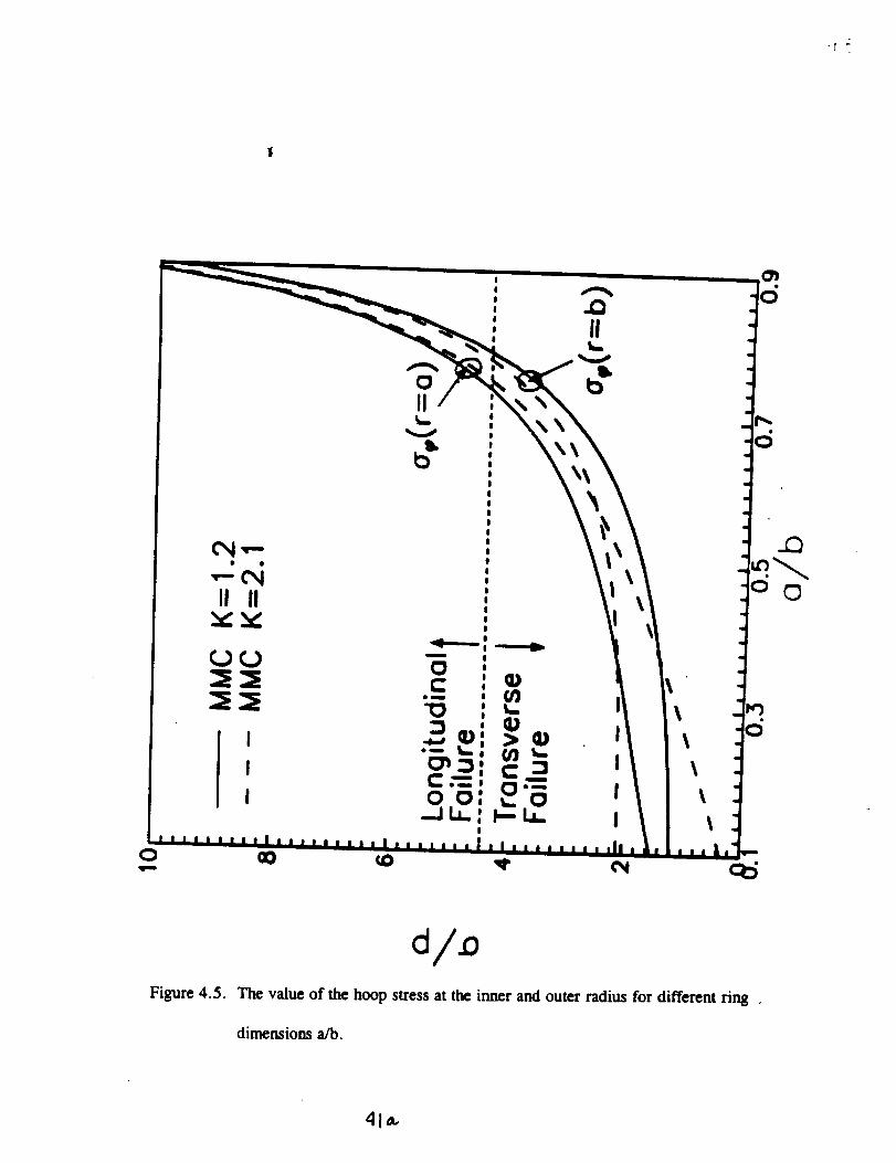
The value of the hoop stress at the inner and outer radius are shown in Figure
4.5 for different ring dimensions a/b. It can be deduced that a tremendous stress
distribution occurs when the interface debonds for small a/b ratios and the maximum
hoop stress can even increase. However, this can be avoided by choosing a larger a/b
ratio and it can be seen that the stress redistribution is modest for a/b larger than 0.7.
This result implies that this type of stress redistribution can sometimes be avoided by
choosing configurations such that the geometry dictates the stress distribution more
than the constitutive properties.
4.2,2 Stress Concentration, The highest tensile stress concentration for a hole
in a infinite plate illustrated in Figure 4.3b is given by the tensile hoop stress at the
ends of the diameter perpendicular to the loading direction, cf. Lekhnitskii [1944], as:
For a pristine composite loaded in the longitudinal direction, the stress
concentration is 3.4. After the residual stresses have relaxed at the interface, the stress
concentration increases to 4.6. For loading in the transverse direction, the stress
concentration for the pristine composite is 2.7 and it decreases to 2. I for the debonded
composite.
41
-I
!
!, .Q!
, II' S,..
V
oII ,
|_.=
|!!||i|||!
CMT=- ,
._ '!I
!II II|_ ,
©
Figure 4.5. The value of the hoop stress at the inner and outer radius for different ring
dimensions a/b.
410-
4.2.3 Stress Decay. An interesting issue for composites is how far an edge
effect propagates into a component (Saint-Venant's Principle). Edge effects can
propagate much farther into highly anisotropic materials than into isotropic materials.
This observation was studied by Horgan et al., [1972] for the self-equilibrating loading
shown in Figure 4.3c. The approximate stress decay is given by:
_I < Ae-_,x > 0 (4.5a,b)
where
(4.5c)
Equation 4.5c indicates that the edge effect has the slowest decay rate in the stiffest
direction. For the present composite, the longitudinal modulus can be expected to he
unaffected by the debond. An appreciation for the difference in decay rate for the
debonded and pristine composite is given by the ratio of the lengths required to achieve
the same stress level. Use of equation 4.5c gives:
(4.6)
42
This implies that the load diffusion length increases by 40 percent for the debonded
material.
It has been found that the relaxation of the residual compressive stresses at the
fiber-matrix interface causes a reduction in the transverse modulus to a third of the
value for the pristine composite.
The initial in-plane shear response is not affected as strongly as the transverse
tensile response. The shear modulus is reduced to half of the value for the pristine
material. Calculations indicate that the sliding resistance at the interface reduced by
half the value of the pristine material. The limit strength in shear is dictated by a
combination of the matrix strength and the sliding resistance at the interface. This
implies that the limit strength of the composite is only reduced by a factor of 2/3.
Some loadings, such as longitudinal tension, will tend to close the fiber matrix
interface and cause the debonded composite to have the same elastic properties as the
pristine composite. Other loadings, such as transverse tension, will cause portions of
the interface to open up more during loading. This will cause the debonded composite
to have elastic properties that are dependent on the loading. Some of the elastic
symmetry relations do not apply for constants determined from these different loadings.
It was demonstrated that micro-mechanical simulations can be used as an
efficient tool to evaluate the experimental observations. This experience also adds
confidence in the use of this approach in predicting composite behavior.
The present titanium materials composite (TMC) systems with weak interfaces
are candidates for components with complex shapes. The components will he
43
manufactured through complex processes and assemblies of sub-components. The
individual sub-components can therefore be subjected to a number to thermal cycles
with high temperature before service. This can lead to a relaxation of the compressive
stresses at the fiber matrix interface. The relaxation leads to a drastic reduction in the
transverse modulus. A reduction in transverse modulus causes an increase in the
anisotropy of the material, and the stress distribution in a component, consisting of a
debonded composite, can be substantially different from the stress distribution for the
pristine composite. Hence, design calculations should be performed for the pristine and
debonded composite properties to ensure that the component has the required
performance.
44
5.0 CONCLUDINGREMARKS & RECOMMENDATIONS
The theoretical research described herein has provided a fundamental foundation
for future development and evaluation of aligned fibrous composites for potential
application to reinforcing elements for reinforced concrete structures. It has been
demonstrated that projecting the structural performance of components from small
specimen data to the representative structural level is both volume dependent and
configuration dependent. The models and the statistical, Weibull-type theory have been
developed to facilitate prediction of the effect of both volume and loading configuration
and basic strength properties. Although the research has concentrated to a large degree
on a MMC system, with limited discussion of PMC systems and results, the basic
mechanics and approaches can be readily extended to PMC systems with much more
flexible matrix elastic properties. In fact, we highly recommend that the methods
developed here should be further evaluated for realistic fiber and matrix constituents
such as E-glass fiber and vinylester matrices.
Emerging from this research is the prospect of translating the key Weibull
parameters for individual reinforcing filaments into equivalent Weibull parameters for
the unidirectional composite system. Similarly, evaluation of the influence of size
(volume) and loading configuration, i.e., tension versus flexure, are also amenable to
formal development and assessment. An appropriate blend of materials science and
structural mechanics disciplines will be necessary to enable significant scientific and
technological advancement of the general application of composites in civil engineering
45
structural applications. In fact, one of the longer-term goals of our research was to
establish a closer interaction with structural engineering. Nevertheless, we strongly
recommend that further basic research, of an interdisciplinary nature, should be
considered in establishing the groundwork on the mechanisms and characteristics of
ductility potential in PMC's with relatively brittle reinforcing filaments. The linkage
with the implementation of composites as reinforcing elements as viewed by the
structural engineer and concrete technologist is, however, essential in helping to define
the role of both reinforcement stiffness, ductility and interface bond/slip between
reinforcing elements and concrete at the macro-level.
reinforced and prestressed concrete applications
Specific examples would include
and could, potentially, provide
valuable insight for applications-oriented development such as the Advanced Waterfront
Technology Test Site (AWTTS) at NFESC (Port Hueneme).
The parallel experimental research has provided insight into both the grip design
required to facilitate meaningful test data on candidate rebar tensile behavior as well as
an evaluation of the merits of considering development of hybrid rebar configurations.
In the former investigation, the local stress distribution in the grip region was
determined using finite element analysis and these results indicated the presence of a
stress/strain concentration just inside the grip termination location. It was also shown
that the layered structure of hybrid rebar tended to sigmficanfly modify the stress and
strain concentration and resulting distributions in the grip termination region, a factor
that potentially contributes to the strength data generated for the rebar specimens.
46
One of the major difficulties in developing reliable and consistent test data for
both grip design and hybrid rebar evaluation the quality of the specimens available.
Thus, it is strongly recommended that an alternative source of supply should be
explored in ongoing research on grip and rebar experimental evaluations of the type
conducted in this research investigation.
Finally, there is a desperate need for a well planned, rigorous assessment of
long-term durability and environmental effects on current and future low-cost PMC
systems that are candidates for applications in civil engineering in general but, perhaps
even more importantly in waterfront or marine structures. Funded research in this area
appears quite limited in the United States at present, but environmental concerns
remain a major issue for economics/life cycle rationalization.
The UCSB research team is most grateful for the opportunity to conduct this
research investigation for NFESC and, despite the need to cut short the originally
planned period of research to 2 years, we feel we have gained much from the program
and contributed some methodology and data that will prove useful in future research.
The expansion of our involvement with the civil engineering community that was
fueled by this research involvement has included the NSF Offshore Technology
Research Center peer reviews, Federal Highways Advisory Committee on Adhesive-
Technology for civil structural applications and Institute of Mechanics and Materials
(UCSD) Think-Tank on Durability of Advanced Composites in Civil Structures.
47
6.0 REFERENCES
Bain, K.R., Byrnes, M.L. and Jain, S.K., 1985, "Fatigue and Fracture of Titanium,
Aluminides," Allison Gas Turbine, Indianapolis, Indian, EDR 13084.
Bullock R.E.., 1974, "Strength Ratios of Composite Materials
Tension", Journal of Composite Materials," vol. 8, pp. 200-206.
in Flexure and
Coleman, B.D., 1958 "On The Strength of Classical Fibers and Fiber Bundles",
Journal of the Mechanics and Physics of Solids, vol. 7, pp. 60-70.
Cooper G.A. and Kelly A., 1967, "Tensile Properties of Fiber-Reinforced Metals:
Fracture Mechanics," Journal of the Mechanics and Physics of Solids, vol.x, pp.279-
297.
Curtin, W.A., 1993, "Ultimate Strengths of Fiber-Reinforced Ceramics and Metals,"
Composites, vol. 24, pp. 98-102.
Daniels, H.E., 1945, "The Statistical Theory of the Strength of Bundles of Threads-I,"
Proceedings of the Royal Society, vol. A183, pp. 405-435.
48
Gundawardena,S., Jansson,S, and Leckie, F.A., 1993, "Modelingof Anisotropic
Behaviorof WeaklyBondedFiberReinforcedMMC's," Acta Metallurgica,vol. 41,
pp. 3147-3156
Giicer D.E. and Gurland J., 1962, " Comparison of the Statistics of Two Fracture
Modes," Journal of the Mechanics and Physics of Solids, vol. 10, pp. 365-373.
He. M.Y., Evans, A.G. and Cut'tin, W. A., 1993, "The Ultimate Tensile Strength of
Metal and Ceramic-Matrix Composites," Acta Metallurgica, vol. 41, pp. 871-878.
Hild F., Domergue J.M., Leckie F. and Evans A. ,1993, "Tensile and Flexural
Ultimate Strength of Fiber-Reinforced Ceramic-Matrix Composite," to appear in
International Journal of Solids and Structures.
Hild F. and Burr A., 1994, "Localization and Ultimate Tensile Strength of Fiber-
Reinforced Ceramic-Matrix Composites," Mechanics Research Communications, vol.
21, pp. 297-302.
Holte, L.E., Dolan, C.W., Schmidt, R.J., "Epoxy Socketed Anchors for Non-Metallic
Prestressing Tendons," Fiber-Reinforced-Plastic Reinforcement for Concrete
Structures, International Symposium, ACI SP-138, A. Nanni and C.W. Dolan editors,
1993, pp.381-400.
49
Horgan,C.O., 1972 "Saint Venant End Effects in Composites," Journal of Composite
Materials, vol 16, pp. 411-422.
Iyer, S.L., Anigol, M., "Testing and Evaluating Fiberglass, Graphite and Steel
Prestressing Cables for Pretensioned Beams," Advanced Composite Materials in Civil
Engineering Structures, ASCE Materials Division, S. Iyer and R. Sen editors, Las
Vegas, Nevada, January 1991, pp.44-56.
Jansson S., Deve, H.E. and Evans A.G., 1991 " The Anisotropic Mechanical
Properties of a Ti Matrix Composite with SiC Fibers," Metallurgical Transactions, vol.
22A, pp. 2975-2984.
Jam,son S. and Kedward, K.T., 1994, "Ultimate Tensile Strength of Composites
Exhibiting Fiber Fragmentation," to appear in Compositers.
Jansson S. and Leckie, F.A. 1992, "The Mechanics of Failure of Silicon Carbide
Fiber-Reinforced Glass-Matrix Composites," Acta Metallurgica, vol. 40, pp. 2967-
2978.
50
Kelly A. and Tyson , 1965, "Tensile Propertiesof Fiber-ReinforcedMetals:
Copper/Tungsten and Copper/Molybdenum," Journal of the Mechanics and Physics of
Solids, vol. 13, pp 329-350.
Lerch, A.L., Gabb, T.B. and MacKay, R.A., 1990, _Heat Treatment Study of the
SiC/Ti-15-3 Composite System," NASA TP 2970.
Malvar, L.J and Bish, J., "Grip Effects in Tensile Testing of FRP Bars," Non-Metallic
(FRP) Reinforcements for Concrete Structures, Ghent, Belgium, 1995.
Nedle, M.R. and Wisnom, M.R., 1994, "Stress Concentration Factors Around Broken
Fibres in a Unidirectional Carbon Fiber-Reinforced Epoxy," Composites, vol. 25, pp.
549-557.
Neumeister J.M., 1993, "A Constitutive Law for Continuous Fiber Reinforced Brittle
Matrix Composites with Fiber Fragmentation and Stress Recovery," Journal of the
Mechanics and Physics of Solids, vol. 41, pp. 1383-1404.
Phoenix S. L., 1993, "Statistical Issues in the Fracture of Brittle Matrix Fibrous
Composites, _ Composite Science and Technology, vol. 48, pp. 65-80.
51
PhoenixS. L, and Raj R., 1992, " Scalings in Fracture Probabilities for a Brittle
Matrix Fiber Composite," Acta Metallurgica, vol. 37, pp. 2813-2828.
Sippel, T.M., "Design, Testing and Modeling of an Anchorage System for Resin
Bonded Fiberglass Rods used as Prestressing Tendons, _ Advanced Composite
Materials in Bridges and Structures, First International Conference, K.W. Neale and P.
Labossiere eds., Sherbrooke, Quebec, Canada, 1992, pp.363-372.
Sutcu M., 1989, "Weibull Statistics Applied to Fiber Failure in Ceramic Composites
and Work of Fracture, _ Acta Metallurgica, vol. 37, pp. 651-661.
Thouless, M.D. and Evans, A.G.,1988 " Effect of Pull-Out on the Mechanical
Properties of Ceramic Matrix Composites," Acta Metallurgica, vol. 36, pp. 517-522.
Weibull W., 1939, "The Phenomenon of Rupture in Solids," IVA Proceedings,
Stockholm, No 153.
Whitney J.M. and Knight M., 1980, "The Relationship Between Tensile Strength and
Flexure Strength in Fiber-Reinforced Composites," Experimental Mechanics, vol. 15
,pp. 211-216.
52

Zweben,C. andRosen,B.W., 1970, "
Solids, vol. 18, pp. 189-206.
," Journal of the Mechanics and Physics of
53