Embed Size (px)
Citation preview
STRUCTURAL MODELING AND OPENVSP
Overview Presentation
Trevor Laughlin
Laughlin Research, LLC
OpenVSP Workshop 2015
Hampton, Virginia
August 11-13, 2015

Professional Experience
– Managing Member, Laughlin Research, LLC (August 2015–Present)
• Developing tools and methods in the areas of parametric aircraft structural
design and analysis
– Stress lead at Triumph Aerostructures (October 2012–July 2015)
• Bombardier Global 7000/8000 weight savings/trailing edge team
Educational Background
– Master of Science in Aerospace Engineering (2012)
• Georgia Tech
– Bachelor of Science in Aerospace Engineering (2008)
• Iowa State
– NASA Graduate Student Researchers Program (LaRC)
• Structural weight estimation environment for Hybrid Wing Body (HWB)1
INTRODUCTION
Laughlin Research, LLC OpenVSP Workshop 2015 2

INTRODUCTION
Laughlin Research, LLC OpenVSP Workshop 2015 3
HWB structural weight estimation environment developed as part of
NASA GSRP fellowship while at Georgia Tech1.
Components were integrated using Phoenix Integration’s ModelCenter.
VSP was the
starting point
Matlab scripts
generated
Patran session
files to generate
structural
geometry and
FEM.
Automation of
HyperSizer
using API.
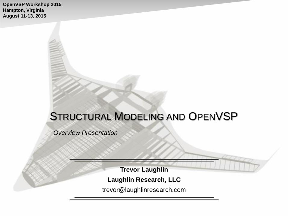
MOTIVATION
Laughlin Research, LLC OpenVSP Workshop 2015 4
Design sketch
Swet/Sref, L/Dmax, L/Dcruise Aspect ratio selection
Engine SFC data Wfuel/WTO
WTO guess
WTO equation Wempty/WTO equation
Calculated WTO & Wfuel
Design objective & sizing mission

MOTIVATION
Laughlin Research, LLC OpenVSP Workshop 2015 5
Design sketch
Swet/Sref, L/Dmax, L/Dcruise Aspect ratio selection
Engine SFC data Wfuel/WTO
WTO guess
WTO equation Wempty/WTO equation
Calculated WTO & Wfuel
Design objective & sizing mission
No historical database available for
unconventional configurations

MOTIVATION
Laughlin Research, LLC OpenVSP Workshop 2015 6
Finite element models are
not necessarily good weight
prediction models
Method Weight Derivation Drivers Examples
Statistical
• Parametric variation of statistical
weight/physical feature
relationships
• Expressed as a fraction of WTO
•OEW vs. WTO
•Wing weight varied by
t/c, AR, area, etc.
Quasi-Analytical
and Analytical
•Weight generated from theoretical
foundation
•Non-optimum weight applied to
theoretical weight
•Box beam wing analysis
•Finite element model for
structural systems
(account for 30-80% of
the actual weight)4
Actual Design
•Part weight calculated and actual
weights
•Part volume × density
•Area × weight per unit
area

Structural design and analysis tools vary from company to company. Improvements are
needed in these tools, including life prediction tools, weight estimation tools, thermal
stress analysis tools, and rapid preliminary sizing tools. These improvements would give
the U.S. aerospace industry a distinct competitive advantage.
-U.S. Supersonic Commercial Aircraft: Assessing NASA's High Speed Research Program (1997)3
MOTIVATION
Laughlin Research, LLC OpenVSP Workshop 2015 7

The design looked promising, but the biggest uncertainty was in estimating wing weight,
which had a large impact on the calculated performance. “The weight range of
uncertainty in Phase 1 was really big, from better to worse than a conventional wing.”
- Marty Bradley, Sugar principal investigator at Boeing Research & Technology (2014)5
Note: Phase 2 included a detailed finite element model and predicted a favorable wing weight at the lower end of the
spectrum.
MOTIVATION
Laughlin Research, LLC OpenVSP Workshop 2015 8

Develop a parametric aircraft structural modeling tool to:
1. Provide improved structural weight estimates during the early stages of
design using geometry-driven analyses
• Results that engineers can use to confidently select the “best” design
2. Enable efficient, robust, and parametric structural modeling for
concept evaluation
• Results should be available in a short amount of time (days if not hours)
• Spend less time building models and more time learning more about the
problem you’re trying to solve
3. Generate models that can be transitioned directly into later design
stages and matured
• Ease the transition between design phases
OBJECTIVES
Laughlin Research, LLC OpenVSP Workshop 2015 9

Parameters and methods for structural modeling should be
consistent with “The VSP Way”:
– Intuitive, quick, and easy
– Familiar to aerospace designers
So, what are these parameters?
STRUCTURAL MODELING
Laughlin Research, LLC OpenVSP Workshop 2015 10
Spars defined
parametrically in wing
coordinate system
Rib defined
relative to spars
How to find all enclosed
skin panels?
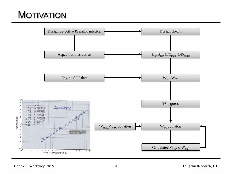
Customized geometry and structural modeling tool developed in
Python using a mixture of parametric and “free-form” geometry
STRUCTURAL MODELING
Laughlin Research, LLC OpenVSP Workshop 2015 11
NASA VSP
model
NASA VSP model
reconstructed in
structural modeling tool Structural layout including spars, ribs,
stringers, and frames
STRUCTURAL MODELING
Laughlin Research, LLC OpenVSP Workshop 2015 12
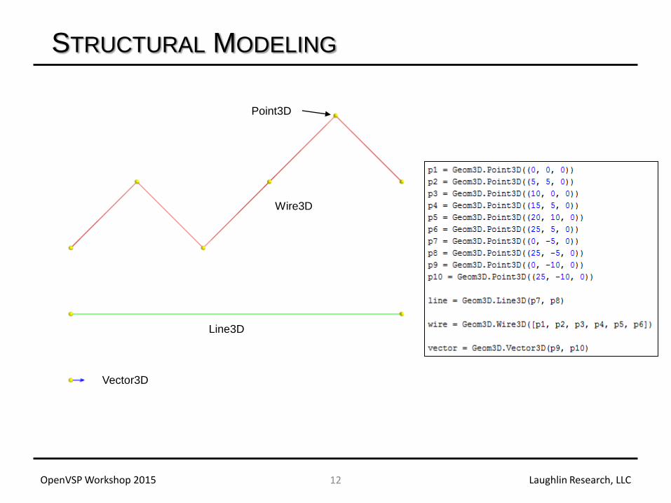
Vector3D
Line3D
Wire3D
Point3D

Geometry utilities were developed to perform common operations
including
– Intersections
• line-line
• line-plane
• line-wire
• wire-plane
• wire-wire
– Projections
• point-to-line
• point-to-plane
• point-to-wire
• point-to-surface
– Point inversion
STRUCTURAL MODELING
Laughlin Research, LLC OpenVSP Workshop 2015 13

Reconstruct VSP Hermite data using first-order surfaces into new
Wing and Fuselage geometry components
STRUCTURAL MODELING
Laughlin Research, LLC OpenVSP Workshop 2015 14
VSP model Wires created from Hermite data
STRUCTURAL MODELING
Laughlin Research, LLC OpenVSP Workshop 2015 15
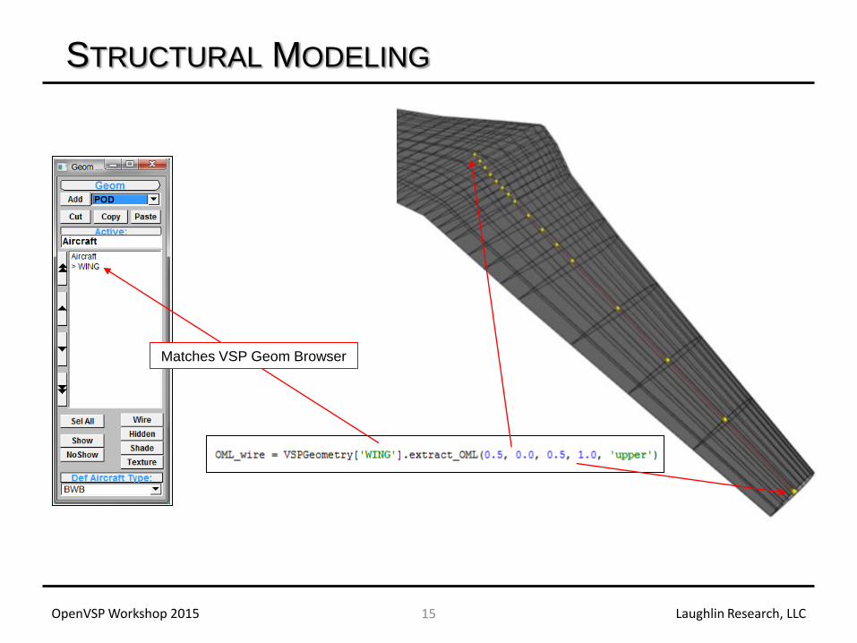
Matches VSP Geom Browser

Built structural components using geometry package and object-
oriented approach
– Wing
• Spar, rib, stringer
– Fuselage
• Frame, longeron, bulkhead, floor, floor post
– Miscellaneous
• Beam, rigid body components
Three methods to define structural geometry
1. Parametric coordinates (u, v) of parent geometry (wing or fuselage
component)
2. Relative to other structure using parametric coordinates of structural
component
3. Use free-form geometry
STRUCTURAL MODELING
Laughlin Research, LLC OpenVSP Workshop 2015 16

STRUCTURAL MODELING
Laughlin Research, LLC OpenVSP Workshop 2015 17
Sample script for front and rear spar
Changed only the x-position of
spar and the name of the part
Method 1: Using parametric coordinates of parent geometry

STRUCTURAL MODELING
Laughlin Research, LLC OpenVSP Workshop 2015 18
Sample code for wing box ribs
Top view
Normal projection by default
Method 2: Relative to other structure

STRUCTURAL MODELING
Laughlin Research, LLC OpenVSP Workshop 2015 19
Merge wires of front spar and tip
rib to enable seamless projection
of points for stringer definition
Evenly spaced points are created
along the upper wire of the root
rib. A projection vector is defined
parallel to the rear spar.
Method 3: Free-form geometry

STRUCTURAL MODELING
Laughlin Research, LLC OpenVSP Workshop 2015 20
Completed wing box example
generated in less then 10 seconds.
Looking down the wing

STRUCTURAL MODELING
Laughlin Research, LLC OpenVSP Workshop 2015 21
Using the same script that constructs the
wing (minus the stringers), the tail structure
can be generated by simply providing a
different VSP wing component.

STRUCTURAL MODELING
Laughlin Research, LLC OpenVSP Workshop 2015 22
Business jet Transport

STRUCTURAL MODELING
Laughlin Research, LLC OpenVSP Workshop 2015 23
Hybrid Wing Body Supersonic Concept

Identifying and constructing enclosed skin panels is a critical step
and needs to be very robust
– Do not constrain the user’s ability to define the internal structure
– Enclosed bays are easy to see, but how does a blind computer know?
STRUCTURAL MODELING
Laughlin Research, LLC OpenVSP Workshop 2015 24
How to find all enclosed
skin panels?

STRUCTURAL MODELING
Laughlin Research, LLC OpenVSP Workshop 2015 25
Front and rear spar only Front, rear, and mid spar
only (one line of code)

STRUCTURAL MODELING
Laughlin Research, LLC OpenVSP Workshop 2015 26
989 unique skin bays found between
spars, ribs, and stringers

STRUCTURAL MODELING
Laughlin Research, LLC OpenVSP Workshop 2015 27
Random number generator
used to define ribs and test
robustness.
Surfaces not shown due to
excessive number of edges, but
offset red wires show the process
was successful.

Intersection methods for structure within different components (wing-
to-fuse)
Export loaded grids for loads transfer and application using Discrete
Data Transfer Between Dissimilar Meshes (DDTBDM)2
Link to HyperSizer
– Ideal for stiffened panel with axial and shear loads
– Need to develop additional tools and methods for other types of
structure
Control surfaces and linkage to primary structure
User interface
FUTURE WORK
Laughlin Research, LLC OpenVSP Workshop 2015 28

Questions?
THANK YOU
Laughlin Research, LLC OpenVSP Workshop 2015 29

1. Laughlin, T.W., “A Parametric and Physics-Based Approach to Structural Weight Estimation of the Hybrid Wing Body Aircraft,” 51st
AIAA Aerospace Sciences Meeting including the New Horizons Forum and Aerospace Expedition, No. AIAA 2013-1082, Grapevine, TX,
07-10 January 2013
2. Samareh, J. A., “Discrete Data Transfer Technique for Fluid-Structure Interaction,” 18th AIAA Computational Fluid Dynamics
Conference, No. AIAA 2007-4309, Miami, FL, 25-28 June 2007.
3. U.S. Supersonic Commercial Aircraft: Assessing NASA's High Speed Research Program. Washington, D.C.: National Academy, 1997.
Print.
4. Pincha, P. J., “Algorithmic mass-factoring of finite element model analyses, an update: Grid-density sensitivity," in 42nd Annual
Conference of the Society of Allied Weight Engineers, Inc., no. 1524, (Anaheim, CA), 23-25 May 1983.
5. Aviation Week & Space Technology, “NASA, Boeing Test Low-Drag Truss-Braced Wing Concept”, aviationweek.com/awin/nasa-
boeing-test-low-drag-truss-braced-wing-concept, 27 January 2014
REFERENCES
Laughlin Research, LLC OpenVSP Workshop 2015 30