Embed Size (px)
Citation preview

STRUCTURAL ISSUES IN RESIDENTIAL CONSTRUCTIONPART IIPresented by:Susan L. Lasecki P.E., S.E.
04-27-2014

Presentation Outline
Basements: Basis of wall bracing Load Paths from Roof to Foundation Roof Framing Floor Framing Wall Framing
Lateral Loads Basement walls Wind Loads and Shear walls – Future presentation

Retaining and Basement Wall Basics
Understanding Soil Loads: Active Pressure: The horizontal load
exerted on a retaining wall when some small degree of wall movement is anticipated. This pressure is used on retaining walls
Passive Pressure: The horizontal force soil exerts when being pressed against by active soil pressure
At-Rest Pressure: The horizontal load exerted on a wall when no wall movement is anticipated. This pressure is used on basement walls.

Full Height Basement Wall Loads
Image from Home Systems Data, Denver, USAhttp://www.hsdi.us/library/
Loads Total horizontal load
W=q*h^2/2 q varies based on soil
type Top reaction = W/3 Bottom reaction =
2/3W

Lateral Soil Load Chart Wisconsin Residential Code
Items C and D in the footnotes are unclear. In my experience, ALL masonry and concrete basement walls should be considered rigid and designed for the 60 or 100 psf loads.These values are somewhat conservative and a geotechnical investigation would yield pressures of 50 to 80 psf loads
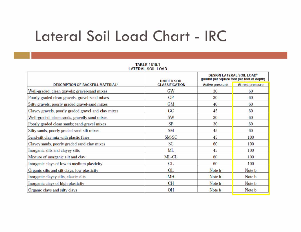
Lateral Soil Load Chart - IRC

Sample Loads
Clay Soil: Total horizontal
load W=100*8’x8’/2=3200 plf
Top reaction = 1066 plf
Bottom reaction = 2133 plf
Design example: Wall = 8’ tall with 8’ of unbalanced fill
Granular Soil: Total horizontal
load W=60*8’x8’/2= 1920 plf
Top reaction = 640 plf
Bottom reaction = 1280 plf
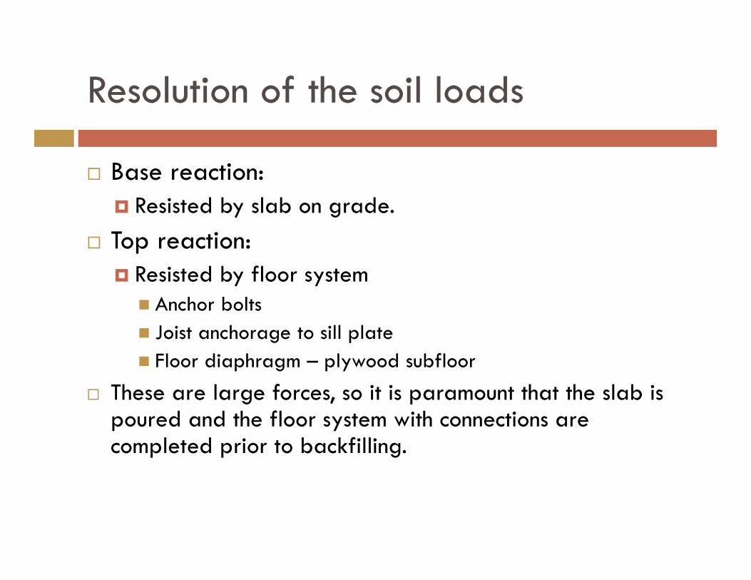
Resolution of the soil loads
Base reaction: Resisted by slab on grade.
Top reaction: Resisted by floor system Anchor bolts Joist anchorage to sill plate Floor diaphragm – plywood subfloor
These are large forces, so it is paramount that the slab is poured and the floor system with connections are completed prior to backfilling.

Anchor Bolt Connection
WI-UDC & IRC Requires ½” dia bolt at 6’-0” o.c.
(min)
Capacity of bolt against failure in wood treated sill plate: =410 lbs per bolt (NDS – Table
11E and by calculation) By calculation, these bolts are
needed every 5” to 8” o.c. Code modifications are needed
for both building codes or alternate methods of attachment should be developed.

Joist to sill anchorage
Typical connection: Toenail: (3) 8d Capacity = 184 lbs Required capacity at 16” o.c. =
853 lbs to 1421 lbs Additional Code changes are
needed here. Suggest requiring the usage of manufactured products such as USP or Simpson connectors

The Floor Diaphragm – how it works
The reaction at the top of the wall acts on the floor diaphragm and is transferred into the walls parallel to the load which act as shear walls
If the basement does not have any exposure, the system will act in equilibrium as the forces on either side of the diaphragm will be equal and opposite.
If the basement is exposed on one side, the load will be unbalanced. Improper connections can lead to the outside exposed wall bowing outward. This is even more problematic where walls are partial height.
Image from: Precast/Prestressed Concrete Institute. 2010 PCI Design Handbook, 7th Edition. pp 4-56
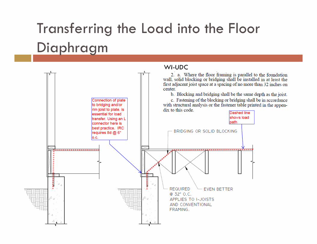
Transferring the Load into the Floor Diaphragm
WI-UDC

Bridging
Bridging/Blocking –Conventional wood framing Diagonal Solid

Partial Height Foundation WallsObserved ConditionPotential failure: Rotation of the frost wall inward Excessive rotation could cause a
first floor framing collapseRepair Methods – for existing conditions Install wood or metal studs full
height inside the wall capable of supporting full lateral load. Anchor studs to slab on grade and wood floor framing above.

Partial Height Foundation WallsCode RequirementsWI-UDC SPS 321.18 Foundations. (1) GENERAL. (a) Design. Foundation
walls shall be designed and constructed to support the vertical loads of the dwelling, lateral soil pressure, and other loads without exceeding the allowable stresses of the materials of which the foundations are constructed.
(b) Lateral support at base. Lateral support such as floor slab or framing shall be provided at the base of foundation walls.
(c) Lateral support at top. Lateral support shall be provided at the top of the foundation walls by one of the following: 2. Structural analysis. A system designed through structural analysis 3. Anchor bolts. a. Structural steel anchor bolts, at least ½inch in diameter,
embedded at least 7 inches into the [concrete or] grouted masonry with a maximum spacing of 72 inches and located within 18 inches of wall corners.
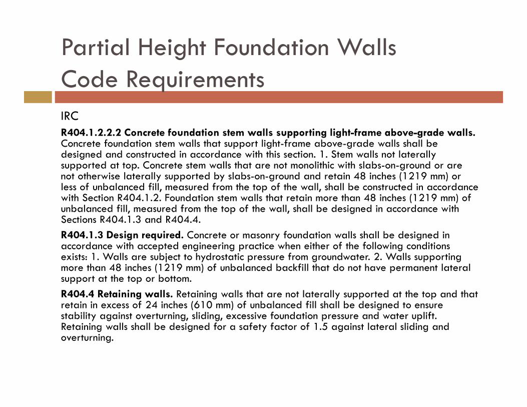
Partial Height Foundation WallsCode RequirementsIRCR404.1.2.2.2 Concrete foundation stem walls supporting light-frame above-grade walls.Concrete foundation stem walls that support light-frame above-grade walls shall be designed and constructed in accordance with this section. 1. Stem walls not laterally supported at top. Concrete stem walls that are not monolithic with slabs-on-ground or are not otherwise laterally supported by slabs-on-ground and retain 48 inches (1219 mm) or less of unbalanced fill, measured from the top of the wall, shall be constructed in accordance with Section R404.1.2. Foundation stem walls that retain more than 48 inches (1219 mm) of unbalanced fill, measured from the top of the wall, shall be designed in accordance with Sections R404.1.3 and R404.4. R404.1.3 Design required. Concrete or masonry foundation walls shall be designed in accordance with accepted engineering practice when either of the following conditions exists: 1. Walls are subject to hydrostatic pressure from groundwater. 2. Walls supporting more than 48 inches (1219 mm) of unbalanced backfill that do not have permanent lateral support at the top or bottom. R404.4 Retaining walls. Retaining walls that are not laterally supported at the top and that retain in excess of 24 inches (610 mm) of unbalanced fill shall be designed to ensure stability against overturning, sliding, excessive foundation pressure and water uplift. Retaining walls shall be designed for a safety factor of 1.5 against lateral sliding and overturning.

Partial Height Foundation Walls
Correct Design Condition Design lower portion of wall as
a retaining wall. Wall needs to be connected to
footing with dowels at uniform spacing.
Connection between wall and footing is considered “fixed” rather than hinged.

Topics from your Suggestions
Foundations:
FROST WALLS AT GARAGE DOORS
Condition Some contractors discontinue the frost walls at
garage doors. Concerns
Post loads at either side of the garage door. At load bearing walls, foundations may not be sufficient.
Frost heave. Edge of slab support at entry will not be
present and over time slab will likely settle and door will not close properly.

Foundations:
SILL PLATE INSTALLATION AND ANCHORAGE
Condition Cantilevered bottom plate overhanging
edge of foundation wall by up to 2” Concerns
Anchor bolts may not have enough distance to edge of concrete
If the bolt is installed at the edge of the wood plate, it may tear out easily since they are already insufficient to resist lateral load.

Footings and Slabs – Rebar Placement
Purpose of Rebar Provide flexural reinforcement at
bottom of footing Placement
Near bottom of footing with 3” of cover
Consequences of improperly placed rebar? Footing may fail under load
Purpose of Rebar Provide temperature and
shrinkage reinforcement (i.e. hold concrete together once it cracks)
Placement At t/3 from top of slab, but not
less than 1 ½” Consequences of improperly
placed rebar? Waste of money and will not
hold the slab together if cracks develop.
Fiber reinforcement is a good alternative
Footings Slabs

Footings – Rebar Placement
Footings

Slabs – Rebar Placement
Slabs

Deck Foundations
Frost protected deck foundations

Advantages and Disadvantages
Advantages Greatest design flexibility Highest possible capacity Good corrosion protection
for the wood posts Disadvantages
Highest cost Longest construction time Post connection is pinned,
requires deck bracing Greatest amount of
excavation
Advantages Good corrosion protection
for the wood posts Lower cost Readily available material Short construction time
Disadvantages Low capacity Post connection is pinned,
requires deck bracing
Pier and Footing Sonotube

Advantages and Disadvantages
Advantages Good capacity Good corrosion protection
for the wood posts Fast construction time
Disadvantages Higher cost Material availability Post connection is pinned,
requires deck bracing.
Advantages Lower cost Readily available material Short construction time Low material cost Post is somewhat fixed and
more rigid than pinned connection.
Disadvantages Low capacity Wood post subject to
deterioration and cannot be readily inspected
Big Foot or other proprietary pier “Cookie” with Granular Backfill

Basement Egress Window Framing
Question: When installing egress windows, is there a required or recommended thickness above the window and is reinforcement required?
There are two structural implications Capacity of “header” above window Capacity of wall adjacent to window

Basement Egress Window Framing
Options shown: Bond Beam Lintel CIP wall with integral
beam above
Other options Steel Lintel Treated wood beam

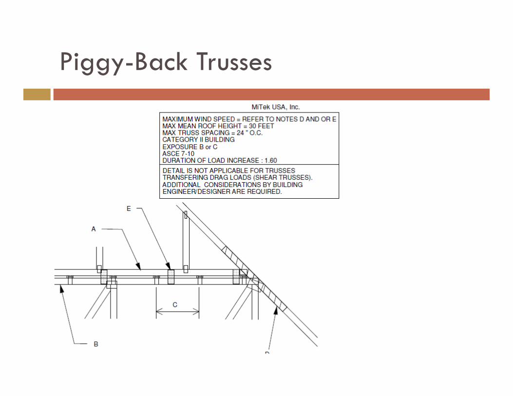
Piggy-Back Trusses
Condition: Piggyback connection is often not a direct connection and load transfer relies on sheathing overlap.
Concern Trusses are frequently installed with the incorrect amount of sheathing overlap.
Solution: Use light gage connectors between structural truss and piggyback truss.
Piggy-Back Trusses

Dormer Framing
Following the load path… The dormer is simply another
“window” opening A header is required above and
below. Hangers should be used. Additional rafters (king studs) are
required on either side of the opening
General rule.. However many rafters have been cut to make the opening, add half that amount either side for support of opening. Must be nailed together in accordance with NDS
Example: 4 rafters have been cut to make a dormer (5’-4” wide). Use (2) additional rafters on either side of opening to carry this load.
Wider openings should be designed by an engineer and may require LVL members

Load Bearing Wood Studs
Capacity of studs is based on: Max spacing. Assumed loads. Stud grade species Fully braced studs in weak direction. Application of sheathing or drywall on one side
or Blocking at 4’-0” o.c. (minimum)

Gravity Design – Wood walls
WI - UDC Maximum allowable unbraced height for a load bearing wall is 10’-0”
without additional engineering

Gravity Design – Wood walls
IRC Maximum allowable unbraced height for a load bearing wall is 10’-0”
without additional engineering
a. Listed heights are distances between points of lateral support placed perpendicular to the plane of the wall. Increases in unsupported height are permitted where justified by analysis.
b. Shall not be used in exterior walls.
c. A habitable attic assembly supported by 2 × 4 studs is limited to a roof span of 32 feet. Where the roof span exceeds 32 feet, the wall studs shall be increased to 2 × 6 or the studs shall be designed in accordance with accepted engineering practice.

What Happens if the Walls are NOT braced?
The wall will be more than 200% overstressed due to the weak axis bending!

Code Changes
a. Listed heights are distances between points of lateral support placed perpendicular to the plane of the wall. Bearing walls shall be sheathed on at least one side or bridging shall be installed not greater than 4 feet apart measured vertically from either end of the stud. Increases in unsupported height are permitted where in compliance with exception 2 of Section R602.3.1 or designed in accordance with accepted engineering practice.
None which specifically address weak axis bracing for interior load bearing walls… yet.
IRC WI - UDC

Roof Truss – Gable End Framing
Gable End Framing Top of wall bracing typically accomplished by attachment of drywall sheathing to
truss bottom chord which is then transferred into the perpendicular walls
Illustration from the Alpine Encyclopedia of Trusses

Roof Truss –Attachment of Gable End Framing 2 – Attachments
Bottom chord to top of wall. Truss manufacturers
require this to be designed by EOR
LTP4 used in this example for shear transfer.
Can also use angle type brackets – especially where there is a ceiling.
Top of wall and bottom chord to diagonal brace. Gable end brace
connector (typically not required if there is a ceiling).
Note: ceiling is present, but it was a small area and not sufficient to be used for a diaphragm

Roof Truss – Gable End Framing
Gable End Framing Diagonal bracing used to transfer the wind reaction to the wood
roof diaphragm
Illustration from the Commentary for Permanent Bracing of Metal Plate Connected Wood Trusses, John E. Meeks

Stairway Framing
Load path for this example: Stringers bear on
top plate of load bearing wall
Opening in wall below stairs is supported by a header.
Image from: American Forest & Paper Assoc: Details for Conventional Wood Frame Construction

Stairway Framing
Load path for this example: Stringers bear on
header Header is
supported by double trimmers

Stairway Framing
Wood stringer support methods: Stringer specific
attachment Use of angles each
side of stringer Use of traditional
joist hangers with blocking to make up bottom slope of stringer.

Questions?
Also, please feel free to ask questions via phone or email at: [email protected] 414-540-8755


![[Architecture eBook] Residential Structural Design Guide 2000 - PDR](https://img.dokumen.tips/doc/110x75/55cf9cc0550346d033aae9c1/architecture-ebook-residential-structural-design-guide-2000-pdr.jpg)