Embed Size (px)
Citation preview

Structural Geotechnical Report
Retaining Wall Replacements
Various Locations DuPage County, Illinois
Prepared for
Design Section Engineer Team: Knight E/A, Inc.
Prepared by:
April 18, 2018

.
April 18, 2018 Mr. Frank Williams, P.E. Knight E/A, Inc. 631 East Boughton Road Bolingbrook, IL 60440 Structural Geotechnical Report Retaining Wall Replacements Various Locations DuPage County Dear Mr. Williams: Attached is a copy of the Structural Geotechnical Report for the above referenced project. The report provides a brief description of the site investigation, site conditions and foundation recommendations. The project includes the replacement of 4 individual walls at various locations in DuPage County. The site investigation included advancing one (1) soil boring to a depth of 20 feet at each of the wall locations. Should you have any questions or require additional information, please call us at 630‐994‐2600. Sincerely,
Charlie Johnson, P.E. Dawn Edgell, P.E. Project Engineer Sr. Project Engineer
623 Cooper Court Schaumburg, IL 60173
Integrity | Quality | Reliability

TOC- 1
TABLE OF CONTENTS 1.0 INTRODUCTION ................................................................................................................. 1
1.1 Site Conditions ......................................................................................................... 2
1.2 Proposed Retaining Wall Information ........................................................................ 2
1.3 Regional Geology ...................................................................................................... 3
2.0 SITE SUBSURFACE EXPLORATION PROGRAM ........................................................... 4
2.1 Subsurface Exploration Program ................................................................................ 4
2.2 Laboratory Testing Program ...................................................................................... 5
2.3 Subsurface Conditions ............................................................................................... 5
2.3.1 Soil Conditions ‐ Eola Road (RWB‐01) ........................................................................................ 6
2.3.2 Soil Conditions ‐ Winfield Road (RWB‐02) .................................................................................. 6
2.3.3 Soil Conditions ‐ Yackley Road (RWB‐03) ................................................................................... 6
2.3.4 Soil Conditions ‐ 55th Street (RWB‐04) ........................................................................................ 7
2.3.5 Groundwater Conditions ........................................................................................................... 7
3.0 GEOTECHNICAL ANALYSES ..................................................................................................... 9
3.1 Derivation of Soil Parameters for Design .................................................................... 9
3.2 Seismic Parameters ................................................................................................. 12
4.0 GEOTECHNICAL RECOMMENDATIONS ...................................................................... 14
4.1 Retaining Wall Design Analysis ................................................................................ 14
4.1.1 Wall and Embankment Settlement........................................................................... 15
4.1.2 Slope Stability Analyses ........................................................................................... 15
4.1.3 Slope Stability Results .............................................................................................................. 16
4.2 Retaining Wall Design Recommendations................................................................. 17
4.2.1 Lateral Earth Pressures and Loading ......................................................................................... 19
5.0 CONSTRUCTION CONSIDERATIONS ....................................................................................... 22
5.1 Existing Utilities ...................................................................................................... 22
5.2 Excavations ............................................................................................................ 22
5.3 Borrow Material and Compaction Requirements ...................................................... 22
5.4 Groundwater Management ..................................................................................... 24
6.0 LIMITATIONS ...................................................................................................................... 25

Figure Figure 1 Project Location Maps Tables Table 1 Wall Summaries Table 2 Boring Summary Table 3 Groundwater Summary Tables 4a to 4d Summary of On‐site Soil Parameters Table 5 Seismic Parameters Table 6 Proposed Wall Design Summaries Table 7 Wall Descriptions Table 8 Stability Analyses Results Table 9 Foundation Recommendations Table 10 LRFD Load Factors for Retaining Wall Design Table 11 Lateral Earth Pressures Soil Parameters Table 12 Equivalent Height of Soil for Vehicular Loading on Retaining Wall Table 13 Structural Fill Soil Properties Appendices Appendix A Site Photographs Appendix B Retaining Wall Boring Location Plans Appendix C Soil Boring Logs Appendix D Slope Stability Analyses Exhibits

1
Structural Geotechnical Report Multiple Retaining Wall Replacements
Various Locations DuPage County, Illinois
1.0 INTRODUCTION GSG Consultants, Inc. (GSG) completed a geotechnical investigation for the replacement of 4 separate retaining wall structures. The walls are located in Aurora, Warrenville, Lisle and Hinsdale in DuPage County, Illinois. The purpose of the investigation was to explore the subsurface conditions, to determine engineering properties of the subsurface soils, and develop design and construction recommendations for each of the projects.
Figure 1: Overall Project Location Map

Retaining Wall Replacements DuPage County
2
1.1 Site Conditions The project in Aurora is located on North Eola Road, north of the intersection with North Aurora Road. There are residential neighborhoods on either side of the roadway, and immediately behind the existing wall, with a high school just to the north. The existing wall is a timber wall, approximately 6 feet high. The project in Warrenville is located along South Winfield Road. Winfield road runs north‐south crossing Warrenville Road just south of the site location. There are residential neighborhoods on either side of the roadway, and immediately behind the existing wall, with a commercial area just south at Warrenville Road. The existing wall is a brick/stone wall, approximately 4 feet high. The project in Lisle is located along southbound Yackley Avenue, which runs north‐south crossing Ogden Avenue about ½ mile north of the site location. There is a residential neighborhood to the west and an industrial/commercial park to the east. The existing wall is a modular block wall approximately 4.5 feet high. The project in Hinsdale is located on 55th Street immediately adjacent to the high school. 55th Street runs east‐west crossing Route 83 just west of the site location. The existing wall is a modular block wall approximately 2.5 feet high. The curb line for 55th Street is located on the top of the wall, with a sidewalk and fence along the bottom of the wall. Photographs of each site and the existing walls are included in Appendix A.
1.2 Proposed Retaining Wall Information A technical memo (dated November 2, 2017) prepared by Knight for DuPage County Department of Transportation provided a structural review of various retaining walls on routes across DuPage County. Based on the review of the existing walls, several repair or replacement options were provided based on the overall condition of the existing structures. Knight has provided preliminary plans for four of the walls based on the structural recommendations. Table 1 presents a summary of the existing retaining walls at each location and the proposed repair or replacement option for each site.

Retaining Wall Replacements DuPage County
3
Table 1 – Wall Summaries
Wall Location Wall Designation
Existing Wall Type
Proposed Repair or
Replacement
Estimated Wall Length
(ft)
Maximum Wall Height
(ft) Eola Road and Haverhill
Road, Aurora, IL CH 14 Timber Wall Replacement 295 6
Winfield Road and Main Street, Warrenville, IL
CH 13 Modular Concrete Block
Replacement 90 4
Yackley Road and Hitchcock Avenue, Lisle,
IL CH 40
Modular Concrete Block
Replacement 141 4.5
55th Street and Madison Street, Hinsdale, IL
TBD Modular Concrete Block
Replacement 320 2.5
1.3 Regional Geology GSG reviewed several published documents in an effort to determine the regional geological setting in the area of the site. The subject area is located in the eastern portion of DuPage County, Illinois. The surficial geologic deposits in this area are typically glacial drift deposited during the Wisconsin Glacial Age. The geology of the subject area consists of deposits of grey silty clay till as much as 100 feet thick in the subject area. Deposits in the area of RWB‐1 are primarily from the Yorkville Member of the Wedron Formation, described as “characteristically gray clayey till, locally silty, generally with few cobbles and boulders but with abundant small pebbles.” The Deposits in the areas of RWB‐2, RWB‐3, and RWB‐4 are primarily from the Wadsworth Member of the Wedron Formation, described as “mostly grey clayey till”, not conspicuously different from the Yorkville Member, with the exception of the West Chicago Moraine (Present in RWB‐2 and RWB‐3) which is lighter, slightly more silty and contains more gravel lenses. The Wadsworth Member also contains “an abundance of black shale from Mississippian and Devonian formations.” These formations overlie the Silurian System Dolomite (undifferentiated) which consists of almost entirely dolomite that varies from extremely argillaceous, silty, and cherty to exceptionally pure. The bedrock dips slightly east with an average depth of 70 feet below ground surface in the area of RWB‐1 and an average depth of 100 feet below ground surface in the area of RWB‐4.

Retaining Wall Replacements DuPage County
4
2.0 SITE SUBSURFACE EXPLORATION PROGRAM This section describes the subsurface exploration program and laboratory testing program completed as part of this project. 2.1 Subsurface Exploration Program The proposed locations of the soil borings were provided by Knight and were completed in the field based on field conditions and accessibility. The proposed depths of the soil borings were determined by GSG in accordance with the IDOT procedures and requirements, which requires borings to a minimum depth of 20 feet for retaining structures The site subsurface exploration was conducted between March 19th and March 29th, 2018, and included advancing one (1) standard penetration test (SPT) boring to a depth of 20 feet in the vicinity of each of the proposed walls. A summary of the boring completed at each wall location is provided in Table 2 ‐ Boring Summary. All locations were drilled at the base of the wall with the exception of RWB‐4 at 55th Street, which was drilled at the top of the wall. At three locations (Eola, Winfield, and Yackley), hand augers were also completed at the top of each wall, where accessible, to confirm the soil types behind each of the existing walls. The locations of each of the soil borings at each site location are shown in Appendix B – Retaining Wall Boring Location Plans.
Table 2 – Boring Summary Boring
Designation Wall Location Surface Elevation (ft)
Boring Location Drill Rig
RWB‐1 Eola Road and Haverhill Road, Aurora, IL
727.0 North of Wall in Roadway Mobile 57
RWB‐2 Winfield Road and Main Street, Warrenville, IL
714.0 North of Wall in Roadway CME‐75
RWB‐3 Yackley Road and Hitchcock Avenue, Lisle, IL
691.0 Center of Wall in Roadway Mobile 57
RWB‐4 55th Street and Madison Street, Hinsdale, IL
721.0 Center of Wall in Roadway Mobile 57

Retaining Wall Replacements DuPage County
5
The soil borings were drilled using either a truck‐mounted Mobile 57 or CME‐75 drill rig using 3¼‐inch I.D. hollow stem augers. Soil sampling was performed according to AASHTO T 206, "Penetration Test and Split Barrel Sampling of Soils." Soil samples were obtained at 2.5‐foot intervals to the termination depths of 20 feet. Water level measurements were made in each boring when evidence of free groundwater was detected on the drill rods or in the samples. The boreholes were also checked for free water immediately after auger removal, and before filling the open boreholes with soil cuttings and bentonite and surface patched with concrete. GSG’s field representative inspected, visually classified and logged the soil samples during the subsurface exploration activities. They then performed unconfined compressive strength tests on cohesive soil samples using a calibrated Rimac compression tester and a calibrated hand penetrometer in accordance with IDOT procedures and requirements. Representative soil samples were collected from each sample interval and were placed in jars and returned to the laboratory for further testing and evaluation. 2.2 Laboratory Testing Program All samples were inspected in the laboratory to verify the field classifications. A laboratory testing program was undertaken to characterize and determine engineering properties of the subsurface soils encountered in the area of each proposed retaining wall. Moisture content laboratory tests (ASTM D2216/ AASHTO T‐265) were performed on representative soil samples. The laboratory tests were performed in accordance with test procedures outlined in the IDOT Geotechnical Manual (2015), and per ASTM and AASHTO requirements. Based on the laboratory test results, the soils encountered were classified according to the AASHTO and the Illinois Division of Highways (IDH) classification systems. The results of the laboratory testing program are shown along with the field test results in Appendix C ‐ Soil Boring Logs.
2.3 Subsurface Conditions This section provides a brief description of the soils encountered in the borings performed. Variations in the general subsurface soil profile were noted during the drilling activities. Detailed descriptions of the subsurface soils are provided in Appendix C ‐ Soil Boring Logs. The soil boring logs provide specific conditions encountered at each boring location. The soil boring logs include soil descriptions, stratifications, penetration resistance, elevations, location of the samples, and laboratory test data. Unless otherwise noted, soil descriptions indicated on

Retaining Wall Replacements DuPage County
6
boring logs are visual identifications. The stratifications shown on the boring logs represent the conditions only at the actual boring locations and represent the approximate boundary between subsurface materials; however, the actual transition may be gradual. 2.3.1 Soil Conditions ‐ Eola Road (RWB‐01) The pavement thickness at the surface of RWB‐01 consisted of 12 inches of asphalt and 12 inches of sand and gravel base course materials. Immediately below the pavement, sand fill materials were encountered to a depth of 3.5 feet. Below the fill, the boring encountered medium stiff to hard, brown and gray to gray silty clay through the depth of the boring. The boring was terminated in stiff clay at a depth of 20 feet. The hand auger soil sample taken behind the wall contained brown clay similar to the near surface materials in the soil boring. A relatively thin layer of brown and gray clay at a depth of 5 feet had an unconfined strength of 0.5 tsf. Generally, the native clay materials had unconfined compressive strengths ranging from 1.5 to 5 tsf. Groundwater was not encountered either while drilling or after drilling in this boring. 2.3.2 Soil Conditions ‐ Winfield Road (RWB‐02) The pavement thickness at the surface of RWB‐02 consisted of 14 inches of asphalt. Immediately below the asphalt pavement, sand with gravel fill materials were encountered to a depth of 8.5 feet. Cobbles and large gravel were encountered throughout this level. Below the fill, the boring encountered medium dense to dense, brown sand with gravel to the termination depth of 20 feet. The hand auger soil sample taken behind the wall contained brown clay. The SPT N values of the native sands ranged from 21 to 40 blows per foot. Groundwater was encountered while drilling at a depth of 13.5 feet but was not encountered after drilling in this boring. 2.3.3 Soil Conditions ‐ Yackley Road (RWB‐03) The pavement thickness at the surface of RWB‐03 consisted of 12 inches of asphalt and 8 inches of sand and gravel base course materials. Immediately below the pavement, a layer of clay fill materials was encountered to a depth of 3.5 feet. Below the fill, the boring encountered very stiff to hard, brown and gray silty clay to a depth of 12 feet, underlain by medium dense to very dense, brown and gray sand with gravel. Some occasional rock fragments were encountered at a depth of 13.5 feet. The boring was terminated at a depth of 20 feet in the native sands and gravels. The hand auger soil sample taken behind the wall contained brown sand and gravel. Generally, the native clay materials had unconfined compressive strengths ranging from 2.75 to 4.6 tsf. The native sands had SPT N values ranging from 17 to in excess of 50 blows per foot.

Retaining Wall Replacements DuPage County
7
Groundwater was encountered while drilling at a depth of 18.5 feet but was not encountered after drilling in this boring. 2.3.4 Soil Conditions ‐ 55th Street (RWB‐04) The pavement thickness at the surface of RWB‐04 consisted of 6 inches of asphalt, 6 inches of concrete and 8 inches of sand and gravel base course materials. Immediately below the pavement, a layer of clay fill materials was encountered to a depth of 3.5 feet. Below the fill, the boring encountered very stiff, brown and gray to gray silty clay through the depth of the boring. The boring was terminated in very stiff clay at a depth of 20 feet. Generally, the native clay materials had unconfined compressive strengths ranging from 2 to 3.75 tsf. Groundwater was not encountered either while drilling or after drilling in this boring.
2.3.5 Groundwater Conditions Water levels were checked in each boring to determine the general groundwater conditions present at the site, and were measured while drilling and after each boring was completed. None of the borings were left open after completing the boring, and no 24 hour reading was collected due to safety concerns. A summary of the groundwater conditions encountered in each boring is included in each section above and in Table 3.
Table 3 – Groundwater Summary
Boring Designation
Surface Elevation (ft)
While Drilling (ft) Depth/Elevation
After Drilling (ft)
Estimated Long Term Groundwater* (ft)
RWB‐1 727.0 None None 11.5/715.5
RWB‐2 714.0 13.5/700.5 None 19.5/694.5
RWB‐3 691.0 18.5/672.5 None Greater than 20 feet
RWB‐4 721.0 None None 13.5/707.5
*Estimated based on color change of soils from brown to gray
Based on the color change from brown to gray, the anticipated long term groundwater level was estimated for each boring location as shown in Table 3. Water level readings were made in the boreholes at times and under conditions shown on the boring logs and stated in the text of this report. Long term observations in cased borings or piezometers would be necessary to more

Retaining Wall Replacements DuPage County
8
accurately evaluate the long‐term groundwater conditions at the site. However, it should be noted that fluctuations in groundwater level may occur due to variations in nearby creeks, rainfall, other climatic conditions, or other factors not evident at the time measurements were made and reported herein.
Retaining Wall Replacements DuPage County
9
3.0 GEOTECHNICAL ANALYSES This section provides GSG’s geotechnical analysis and recommendations for the design of each of the proposed retaining walls based on the results of the field exploration, laboratory testing, and geotechnical analysis. Subsurface conditions in unexplored locations may vary from those encountered at the boring locations. If structure locations, loadings, or elevations are changed, we request that you contact GSG so that we may re‐evaluate our recommendations. 3.1 Derivation of Soil Parameters for Design GSG determined that the geotechnical parameters to be used for the project design based on the results of field and laboratory test data on individual boring logs as well as our experience. Unit weights, friction angles and shear strength parameters were estimated using corrected standard penetration test (SPT) using published correlations for N values results for the fill and cohesionless soils and in‐situ and laboratory test results for cohesive soils. The SPT values were corrected for hammer efficiency. The hammer efficiency correction factor considers the use of a safety hammer/rope/cat‐head system, generally estimated to be 60% efficient. Thus, correlations should be based upon what is currently termed as N60 data. The efficiency of the automatic hammer for the truck‐mounted Mobile B‐57 and CME‐75 drill rigs are based on previous efficiency testing of the drill rigs. The correction for hammer efficiency is a direct ratio of relative efficiencies as follows:
N60 = N * (98/60) Mobile 57 N60 = N * (72/60) CME‐75
*Where the N value is the field recorded blow counts. Based on the field investigation data collected, generalized soil parameters for use in design are presented in Tables 4a to 4d.

Retaining Wall Replacements DuPage County
10
Table 4a – Summary of On‐Site Soil Parameters Eola Road ‐ RWB‐1
Depth/Elevation (feet) Soil Description
In situ Unit
Weight
γ (pcf)
Undrained Drained
Cohesion c (psf)
Friction Angle φ (Degrees)
Cohesion c (psf)
Friction Angle φ (Degrees)
New Engineered Granular Fill
125 0 32 0 32
Existing Embankment
Brown Clay 130 1,500 0 100 28
725‐723.5 Brown and Gray Sand with Gravel Fill
130 0 30 0 30
723.5‐715.5 Brown and Gray, Stiff to Hard Silty Clay
136 3,300 0 125 28
715.5‐707 Gray, Stiff to Very Stiff
Clay 134 2,900 0 100 28
Table 4b – Summary of On‐Site Soil Parameters
Winfield Road ‐ RWB‐2
Depth/Elevation (feet) Soil Description
In situ Unit
Weight
γ (pcf)
Undrained Drained
Cohesion c (psf)
Friction Angle φ (Degrees)
Cohesion c (psf)
Friction Angle φ (Degrees)
New Engineered Granular Fill
125 0 32 0 32
Existing Embankment
Brown Clay 130 1,500 0 100 28
714‐705.5 Brown Sand with Gravel Fill
130 0 30 0 30
705.5‐694 Brown, Medium Dense to Dense Sand with Gravel
134 0 38 0 38

Retaining Wall Replacements DuPage County
11
Table 4c – Summary of On‐Site Soil Parameters Yackley Road ‐ RWB‐3
Depth/Elevation (feet) Soil Description
In situ Unit
Weight
γ (pcf)
Undrained Drained
Cohesion c (psf)
Friction Angle φ (Degrees)
Cohesion c (psf)
Friction Angle φ (Degrees)
New Engineered Granular Fill
125 0 32 0 32
Existing Embankment
Brown Sand with Gravel Fill
130 0 36 0 36
690‐687.5 Black and Gray
Clay Fill 130 3,500 0 100 28
687.5‐679
Brown and Gray, Very Stiff to Hard Silty
Clay
138 3,700 0 125 32
679‐671
Brown, Medium Dense to Very
Dense Sand with Gravel
136 0 40 0 39

Retaining Wall Replacements DuPage County
12
Table 4d – Summary of On‐Site Soil Parameters 55th Street ‐ RWB‐4
Depth/Elevation (feet) Soil Description
In situ Unit
Weight
γ (pcf)
Undrained Drained
Cohesion c (psf)
Friction Angle φ (Degrees)
Cohesion c (psf)
Friction Angle φ (Degrees)
New Engineered Granular Fill
125 0 32 0 32
720‐717.5 Black and Brown
Clay Fill 130 2,500 0 100 28
717.5‐707 Brown & Gray, Very Stiff Silty
Clay
135 2,800 0 100 28
707‐701 Gray, Very Stiff
Silty Clay 133 2,500 0 100 28
3.2 Seismic Parameters The seismic hazard for the site was analyzed per the IDOT Geotechnical Manual, IDOT Bridge Design Manual, and AASHTO LRFD Bridge Design Specifications. The Seismic Soil Site Class was determined per the requirements of All Geotechnical Manual Users (AGMU) Memo 9.1, Design Guide for Seismic Site Class Determination, and the “Seismic Site Class Determination” Excel spreadsheet provided by IDOT. A global Site Class Definition was determined for this project, and was found to be Soil Site Class D. The Seismic Performance Zone (SPZ) was determined using Figure 2.3.10‐2 in the IDOT Bridge Manual and was found to be Seismic Performance Zone 1. The AASHTO Seismic Design Parameters program was used to determine the peak ground acceleration coefficient (PGA), and the short (SDS) and long (SD1) period design spectral acceleration coefficients. For this section of the project, the SDS and the SD1 were determined using 2014 AASHTO Guide Specifications as shown in Table 5. Given the site location and materials encountered, the potential for liquefaction is minimal.

Retaining Wall Replacements DuPage County
13
Table 5 – Seismic Parameters
Building Code Reference
PGA SDS SD1
2014 AASHTO Guide for LRFD Seismic Bridge Design 0.048g 0.161g 0.089g

Retaining Wall Replacements DuPage County
14
4.0 GEOTECHNICAL RECOMMENDATIONS This section provides recommendations regarding foundation and design parameters for the proposed retaining walls that are to be replaced. The recommendations were developed based on the project information provided by Knight and the results of the site investigations. If there are any significant changes to the project characteristics or if significantly different subsurface conditions are encountered during construction, GSG should be consulted so that the recommendations of this report can be reviewed. The foundation design recommendations were completed per the AASHTO LRFD 7th Edition (2014). 4.1 Retaining Wall Design Analysis The preliminary information provided by Knight indicate that the existing walls will be replaced with either a timber wall with dead man or a modular concrete block wall. Each of these wall types will be supported on shallow foundation systems. The proposed replacement wall type and anticipated wall heights for each of the locations is shown in Table 6.
Table 6 – Proposed Wall Summary
Wall Location Proposed Wall Type
Proposed Repair or
Replacement
Maximum Wall Height (ft)
Eola Road and Haverhill Road, Aurora, IL
Timber with Deadman Spacing
Replacement 6
Winfield Road and Main Street, Warrenville, IL
Modular Concrete Block
Replacement 4
Yackley Avenue and Hitchcock Avenue, Lisle, IL
Modular Concrete Block
Replacement 4.5
55th Street and Madison Street, Hinsdale, IL
Modular Concrete Block
Replacement 2.5

Retaining Wall Replacements DuPage County
15
GSG evaluated the bearing capacity, settlement and global stability to determine the suitability of the proposed retaining systems at each location. 4.1.1 Wall and Embankment Settlement All of the wall locations are to be constructed in embankment cut areas. The estimated settlement due to the placement of fill materials for the construction of the proposed wall is anticipated to be less than 1 inch. 4.1.2 Slope Stability Analyses The wall contractor should confirm stability requirements based on the final wall configuration. The following parameters were used to evaluate each wall:
Table 7 – Wall Descriptions
Eola Road – Timber Wall
Maximum total exposed height of the retaining wall (H)*
6 feet
Estimated total height of retaining wall (H) 7 feet
Winfield Road – Modular Block
Maximum total exposed height of the retaining wall (H)*
4 feet
Estimated total height of retaining wall (H) 5 feet
Yackley Ave – Modular Block
Maximum total exposed height of the retaining wall (H)*
4.5 feet
Estimated total height of retaining wall (H) 5.5 feet
55th Street – Modular Block
Maximum total exposed height of the retaining wall (H)*
2.5 feet
Estimated total height of retaining wall (H) 3.5 feet
All Wall Locations
Unit weight of the retained fill (embankment)
125 pcf
Internal friction angle for the select backfill (native soils)
32 degrees
*Based on preliminary design provided by Knight

Retaining Wall Replacements DuPage County
16
Slide 7.0 is a comprehensive slope stability analysis software that performs limit equilibrium analysis and was used to evaluate the proposed retaining wall geometry for the project. The proposed designs were analyzed based on the preliminary grading and the soils encountered while drilling. Based on the geometry, and the soil borings, global stability analyses were performed for circular failure analysis using the simplified Bishop and Janbu analyses methods. The analyses were performed using the soil parameters in Tables 4a to 4d. 4.1.3 Slope Stability Results Circular failure analyses were evaluated using Bishop and Janbu analyses methods for a short term (undrained) condition and long term (drained) condition for each of the proposed retaining wall geometries. The analyses were performed at the highest elevation/maximum wall height of each proposed wall. Table 8 provides a summary of the stability analyses.
Table 8– Stability Analyses Results
Analysis Exhibit Station Failure Type Factor of Safety Required Minimum
Factor of Safety
Exhibit 1 Eola
Circular – Short Term
7.8 1.5
Exhibit 2 Circular – Long Term
2.3 1.5
Exhibit 3 Winfield
Circular – Short Term
2.1 1.5
Exhibit 4 Circular – Long Term
2.1 1.5
Exhibit 5 Yackley
Circular – Short Term
9.5 1.5
Exhibit 6 Circular – Long Term
3.5 1.5
Exhibit 7 55th Street
Circular – Short Term
25.5 1.5
Exhibit 8 Circular – Long Term
5.1 1.5

Retaining Wall Replacements DuPage County
17
Based on the analyses results, each of the proposed retaining walls meets the minimum factor of safety of 1.5. Appendix D presents copies of the slope stability analyses. 4.2 Retaining Wall Design Recommendations Based on the preliminary design information, GSG understands that the proposed new retaining walls will be either timber with deadman spacing or modular block walls. Based on the results of the subsurface investigation and the design information provided, the proposed retaining walls could be supported upon a shallow, strip footing system, bearing on the very stiff native silty clay materials. Any existing fill materials or soft native clays should be removed down to the suitable native soils. The foundations could then either be designed at the lower elevation or the over excavation should be backfilled to the bearing grade with structural fill. The granular structural fill should be placed in accordance with the construction considerations section of this report. The lateral limit of the engineered fill placed beneath the foundation should extend a minimum 1 foot beyond the outside edges of the footing and from that point outward laterally 1 foot for every 2 feet of fill thickness below the footing. These wall types are typically founded a minimum of 1‐foot, or 1 block height, below finished grade on a 6‐inch thick granular leveling pad. A summary of the anticipated bearing elevation and recommended allowable bearing capacity for each wall location is in Table 9.
Table 9 – Foundation Recommendations
Wall Location
Wall Type
Estimated Bearing Elevation
(ft)
Recommended Allowable Bearing Capacity (psf)
(ASD)*
Comments Anticipated Settlement (inches)
Eola Road and Haverhill
Road, Aurora, IL
Timber with
Deadman Spacing
726.0 3,000**
Undercut soft materials to a depth of 2 feet and replace with structural fill
<1 inch
Winfield Road and
Main Street, Warrenville,
IL
Modular Concrete Block
713.0 4,000 None <1 inch

Retaining Wall Replacements DuPage County
18
*Includes a factor of safety of 3. **Based on recommendations for undercuts discussed further in this report. The actual strip foundation thickness and reinforcement should be determined by a structural analysis. The allowable bearing capacity is based on an allowable total settlement of one inch and differential settlement of one half inch. If any assumptions or design loading information above is not correct or has been changed, GSG should be contacted to re‐evaluate the foundation design recommendations. If the native soils at the base of the foundation become disturbed during excavation, the exposed subgrade should be compacted prior to placing any structural fill. All localized soft or otherwise unsuitable soils should be over‐excavated and replaced with granular structural fill to the proposed foundation grade elevation. Engineering analyses and design of the proposed walls shall be performed using the current AASHTO Load and Resistance Factor Design (LRFD) Methodology as required by the IDOT. LRFD methodology incorporates the use of load factors and resistance factors to account for uncertainty in applied loads and load resistance of structure elements separately. The AASHTO LRFD Bridge Design Specifications outline load factors and combinations for various strength, extreme event, service, and fatigue limit states. Section 11, which outlines geotechnical criteria for retaining walls, of the AASHTO Specifications requires the evaluation of bearing resistance failure, lateral sliding, and overturning at the strength limit state and excessive vertical displacement, excessive lateral displacement, and overall stability at the service limit state. Table 10 provides the load factors to be used in the design of the retaining walls in accordance with AASHTO Table 3.4.1‐1, Load Combinations and Load Factors, and Table 3.4.1‐2, load Factors for Permanent Loads.
Yackley Avenue and Hitchcock Avenue, Lisle, IL
Modular Concrete Block
690.0 3,000 None <1 inch
55th Street and Madison
Street, Hinsdale, IL
Modular Concrete Block
715.0 3,000 None <1 inch

Retaining Wall Replacements DuPage County
19
Table 10 ‐ LRFD Load Factors for Retaining Wall Design
Type of Load
Bearing Resistance Strength IA
Sliding and Eccentricity Strength IB
Settlement Service I
Load Factors for Vertical Loads
Dead Load of Structural Components (DC)
1.25 0.90 1.00
Vertical Earth Pressure Load (EV) 1.35 1.00 1.00 Earth Surcharge Load (ES) 1.50 1.00 Live Load Surcharge (LS) 1.75 1.00
Load Factors for Horizontal Loads
Horizontal Earth Pressure Load (EH) Active At‐Rest AEP for anchored walls
1.50 1.35 1.35
1.00 1.00
Earth Surcharge (ES) 1.50 Live Load Surcharge (LS) 1.75 1.00 1.00
4.2.1 Lateral Earth Pressures and Loading The wall shall be designed to withstand earth and live lateral earth pressures. The lateral earth pressures on retaining walls depend on the type of wall (i.e. restrained or unrestrained), the type of backfill and the method of placement against the wall, and the magnitude of surcharge weight on the ground surface adjacent to the wall. Cast‐in‐Place walls are considered rigid and as such the earth loads may be calculated using active earth pressure for load above the design grade, and both active and passive earth pressures below the design grade. The active earth pressure coefficient (Ka), and the passive earth pressure coefficient (Kp) were determined in accordance with AASHTO Section 3.11.5.3 and 3.11.5.4, respectively. Table 11 presents the recommended lateral earth pressures soil parameters to be used for the proposed wall designs based on the anticipated soil types at each of the sites.
Table 11 – Lateral Earth Pressures Soil Parameters
Soil Type
In‐situ Unit
Weight (pcf) (γ)
Angle of
Internal Friction (φ)
Active Earth
Pressure Coefficient
(Ka)
Passive Earth
Pressure Coefficient
(Kp)
Coefficient of
Subgrade Modulus (pci)
Soil Strain Parameter
E50
New Engineered Granular Fill
125 32 0.28 3.53 90 N/A

Retaining Wall Replacements DuPage County
20
Soil Type
In‐situ Unit
Weight (pcf) (γ)
Angle of
Internal Friction (φ)
Active Earth
Pressure Coefficient
(Ka)
Passive Earth
Pressure Coefficient
(Kp)
Coefficient of
Subgrade Modulus (pci)
Soil Strain Parameter
E50
Eola Road
Brown & Gray, Sand with Gravel
Fill 130 30 0.33 3.0 225 N/A
Brown & Gray, Stiff to Hard Silty
Clay 136 28 0.35 2.77 1,680 0.005
Gray, Stiff to Very Stiff Clay
134 28 0.35 2.77 1,450 0.005
Winfield Road
Brown Sand with Gravel Fill
130 30 0.33 3.0 90 N/A
Brown, Medium Dense to Dense Sand with Gravel
134 38 0.23 4.33 225 N/A
Yackley Road
Black and Gray Clay Fill
130 28 0.35 2.77 1,750 0.005
Brown & Gray, Very Stiff to Hard
Silty Clay 138 32 0.31 3.25 1,850 0.005
Brown, Medium Dense to Very
Dense Sand with Gravel
136 40 0.22 4.51 225 N/A
55th Street

Retaining Wall Replacements DuPage County
21
Soil Type
In‐situ Unit
Weight (pcf) (γ)
Angle of
Internal Friction (φ)
Active Earth
Pressure Coefficient
(Ka)
Passive Earth
Pressure Coefficient
(Kp)
Coefficient of
Subgrade Modulus (pci)
Soil Strain Parameter
E50
Black and Brown Clay Fill
130 28 0.35 2.77 1,250 0.005
Brown and Gray, Very Stiff Silty Clay
135 28 0.35 2.77 1,470 0.005
Gray, Very Stiff Silty Clay
133 28 0.35 2.77 1,250 0.005
Traffic and other surcharge loads should be included in the retaining wall designs as applicable. A live load surcharge shall be applied where vehicular load is expected to act on the surface of the backfill within a distance equal to one‐half the wall height behind the back face of the wall in accordance with Article 3.11.6.4 of AASHTO LRFD Bridge Design Specifications. The live load surcharge may be estimated as a uniform horizontal earth pressure due to an equivalent height (Heq) of soil. Table 12 provides the equivalent heights of soils for vehicular loadings on retaining walls. Table 12 ‐ Equivalent Height of Soil for Vehicular Loading on Retaining Walls Parallel to Traffic
(AASHTO LRFD Manual ‐ Table 3.11.6.4‐2)
Retaining Wall Height (ft) Heq Distance from Wall Back face to Edge of Traffic 0 feet 1.0 feet or Further
5 5.0 feet 2.0 feet 10 3.5 feet 2.0 feet ≥20 2.0 feet 2.0 feet
GSG recommends designing the retaining walls using the drained condition. This could be accomplished by placing a minimum of 2 feet of free draining materials, Porous Granular Embankment, as measured laterally from the back of the wall. The backfill should be placed in accordance with the IDOT SSRBC. Heavy compaction equipment should not be allowed closer than five (5) feet to the retaining wall to prevent inducing high lateral earth pressures and causing wall yielding and/or other damage.
Retaining Wall Replacements DuPage County
22
5.0 Construction Considerations All work performed for the proposed project should conform to the requirements in the IDOT SSRBC (2012). Any deviation from the requirements in the manuals above should be approved by the design engineer. 5.1 Existing Utilities Before proceeding with construction, any existing underground utility lines that will interfere with construction should be completely rerouted or removed from beneath the proposed construction areas. Existing utility lines that are to be abandoned in place should be removed and/or plugged with a minimum of 2 feet of cement grout. All excavations resulting from underground utilities removal activities should be cleaned of loose and disturbed materials, including all previously‐placed backfill, and backfilled with suitable fill materials in accordance with the requirements of this section. During the clearing and stripping operations, positive surface drainage should be maintained to prevent the accumulation of water. 5.2 Excavations The contractor will be responsible to provide a safe excavation during the construction activities of the project. All excavations should be conducted in accordance with applicable federal, state, and local safety regulations, including, but not limited to the Occupational Safety and Health Administration (OSHA) excavation safety standards. Excavation stability and soil pressures on temporary shoring are dependent on soil conditions, depth of excavations, installation procedures, and the magnitude of any surcharge loads on the ground surface adjacent to the excavation. Excavation near existing structures and underground utilities should be performed with extreme care to avoid undermining existing structures. Excavations should not extend below the level of adjacent existing foundations or utilities unless underpinning or other support is installed. It is the responsibility of the contractor for field determinations of applicable conditions and providing adequate shoring for all excavation activities. 5.3 Borrow Material and Compaction Requirements If borrow material is to be used for onsite construction, it should conform to Section 204 “Borrow and Furnish Excavations” of the IDOT Construction Manual (2017). The fill material should be free of organic matter and debris and should be placed and compacted in accordance with Section 205, Embankment, of the IDOT Construction Manual. Earth‐moving operations should be avoided during excessively cold or wet weather to avoid freezing of softening subgrade soils. Suitable structural fill should have the following soil properties:

Retaining Wall Replacements DuPage County
23
Table 13 – Structural Fill Soil Properties
REQUIRED TEST AASHTO METHOD PERMISSIBLE LIMIT
Standard Dry Density (SDD) T 99 (Method C) 90 pcf min.* Organic Content T 194 10 % max.* Percent Silt and Fine Sand T 88 65 % max. ** Plasticity Index T 90 12 % min. ** Liquid Limit T 89 50 % max. Shear Strength (c) at 95 % T 208 or T 234 1,000 psf min.
* As per IDOT Standard Specifications. ** Frost Susceptibility Criteria
Structural fill should be placed in lifts not to exceed 8 inches in loose thickness and compacted to a minimum of 95% of the material’s standard proctor maximum dry density obtained according to the ASTM D698/AASHTO T 99 method. Materials unsatisfactory for use as structural fill include soils classified as silt or organic silt (ML, MH, PT, OL, and OH) in the Unified Classification System (ASTM D2847). Soils with these classifications may be used for general purpose landscaping and in areas where uncontrolled settlement is acceptable. Should fill be placed during cool, wet seasons, the use of granular fill may be necessary since weather conditions will make compaction of cohesive soils more difficult. If water seepage while excavating and backfilling procedures, or where wet conditions are encountered such that the water cannot be removed with conventional sump and pump procedures, GSG recommends placing open grade stone similar to IDOT CA‐7 to stabilize the bottom of the excavation. The CA‐7 stone should be placed to 12 inches above the water level, in 12‐inch lifts, and should be compacted with the use of a heavy smooth drum roller or heavy vibratory plate compactor until stable. The remaining portion of the excavation should be backfilled using approved engineered fill. GSG recommends that foundation excavations, subgrade preparation, and structural fill placement and compaction be inspected by a GSG geotechnical engineer to verify the type and strength of soil materials present at the site and their conformance with the geotechnical recommendations in this report.
Retaining Wall Replacements DuPage County
24
5.4 Groundwater Management GSG does not anticipate groundwater related issues during construction activity at any of the subject sites; however, water may become perched in the existing fill material encountered at the surface of each location. If rainwater run‐off or perched water is accumulated at the base of excavation, the contractor should remove accumulated water using conventional sump pit and pump procedures, and maintain a dry and stable excavation. The location of the sump should be determined by the contractor based on field conditions. During earthmoving activities at the site, grading should be performed to ensure that drainage is maintained throughout the construction period. Water should not be allowed to accumulate in the foundation area either during or after construction. Undercut and excavated areas should be sloped toward one corner to facilitate removal of any collected rainwater or surface run‐off. Grades should be sloped away from the excavations to minimize runoff from entering the areas. If water seepage occurs during footing excavations or where wet conditions are encountered such that the water cannot be removed with conventional sumping, we recommend placing open grade stone similar to IDOT CA‐7 to stabilize the bottom of the excavation below the water table. The CA‐7 stone should be placed to 12 inches above the water table, in 12‐inch lifts, and should be compacted with the use of a heavy smooth drum roller or heavy vibratory plate compactor until stable. The remaining portion of the excavation beneath the footings should be backfilled using approved structural fill.

Retaining Wall Replacements DuPage County
25
6.0 LIMITATIONS
This report has been prepared for the exclusive use of the DuPage County Department of Transportation and its structural consultant. The recommendations provided in the report are specific to the project described herein, and are based on the information obtained at the soil boring locations within the proposed retaining wall area. The analyses performed and the recommendations provided in this report are based on subsurface conditions determined at the location of the borings. This report may not reflect all variations that may occur between boring locations or at some other time, the nature and extent of which may not become evident until during the time of construction. If variations in subsurface conditions become evident after submission of this report, it will be necessary to evaluate their nature and review the recommendations presented herein.

APPENDIX A
SITE PHOTOGRAPHS

Retaining wall on Eola Road facing South at staked location.
RWB‐1 on Eola Road facing North with cleared utilities.

Retaining wall on Winfield Road facing South at staked location.
RWB‐2 on Winfield Road facing South with cleared utilities.

Retaining wall on Yackley Avenue facing West at staked location.
RWB‐3 on Yackley Avenue facing North with cleared utilities.

Retaining wall on 55th Street facing North, wall is left of guardrail.
RWB‐4 on 55th Street facing East with cleared utilities.

APPENDIX B
RETAININGWALL BORING LOCATION PLANS


APPENDIX C
SOIL BORING LOGS

12 inches of Asphalt
12 inches of Sand and Gravel Base
FILL: SAND, with gravel - Brown and Gray - Moist
SILTY CLAY, trace gravel (CL/ML) - Brown and Gray - MediumStiff to Hard - Moist
SILTY CLAY, trace gravel (CL/ML) - Gray - Stiff to Hard - Moist
Bottom of borehole at 20.0 feet.
SS
SS
SS
SS
SS
SS
SS
SS
5-20-18(38)
1-2-2(4)
2-4-5(9)
3-5-7(12)
3-5-7(12)
3-4-5(9)
2-3-4(7)
2-2-3(5)
0.5
4.58
5.00
4.58
3.5
2.08
1.46
56
33
83
67
89
78
89
89
NOTES
LOGGED BY JJR
DRILLING METHOD HSA
HOLE SIZE 3 1/4''
DRILLING CONTRACTOR GSG Drilling GROUND WATER LEVELS:
CHECKED BY CDJ
DATE STARTED 3/19/18 COMPLETED 3/19/18
AT TIME OF DRILLING --- NONE
AT END OF DRILLING --- N/A
AFTER DRILLING --- N/A
GROUND ELEVATION 727.00 ft
GR
AP
HIC
LOG
MATERIAL DESCRIPTION
SA
MP
LE T
YP
EN
UM
BE
R
BLO
WC
OU
NT
S(N
VA
LUE
)
UN
CO
NF
INE
DC
OM
PR
ES
SIO
N(t
sf)
Moisture Content10 20 30 40
SPT N VALUE20 40 60 80
DE
PT
H(f
t)
0
5
10
15
20
Unconfined Compression (tsf)2 4 6 8
RE
CO
VE
RY
(%)
PAGE 1 OF 1BORING NUMBER RWB-1
PROJECT NAME Retaining Wall Repairs
PROJECT LOCATION Dupage County - Eola Road
CLIENT Knight/Dupage County
PROJECT NUMBER 18-2016
GE
OT
EC
H B
H P
LOT
S -
GIN
T S
TD
US
.GD
T -
4/4
/18
08:
14
- \\G
SG
FS
02\P
RO
JEC
TS
- E
NG
INE
ER
ING
\KN
IGH
T\D
UP
AG
E D
OT
- R
ET
AIN
ING
WA
LL R
EP
AIR
\GE
OT
EC
HN
ICA
L\F
IELD
TE
ST
ING
\BO
RIN
G L
OG
S_3
-20-
18.
GP
JGSG Consultants, Inc.623 Cooper CourtSchaumburg, IL

14 inches of Asphalt
FILL: SAND, with gravel - Brown - Moist
Cobbles at 3.5 feet
Cobbles at 6.5 feet
SAND, with gravel (SPG) - Brown - Medium Dense to Dense -Moist to Wet
SAND, with gravel (SPG) - Gray - Medium Dense - WetBottom of borehole at 20.0 feet.
SS1
SS2
SS3
SS4
SS5
SS6
6-12-20(32)
25
20
22-20-20(40)
9-9-22(31)
6-9-12(21)
11
6
17
56
83
78
NOTES
LOGGED BY CDJ
DRILLING METHOD HSA
HOLE SIZE 3 1/4''
DRILLING CONTRACTOR GSG Drilling GROUND WATER LEVELS:
CHECKED BY MC
DATE STARTED 3/29/18 COMPLETED 3/29/18
AT TIME OF DRILLING --- 13.5
AT END OF DRILLING --- N/A
AFTER DRILLING --- N/A
GROUND ELEVATION 714.00 ft
GR
AP
HIC
LOG
MATERIAL DESCRIPTION
SA
MP
LE T
YP
EN
UM
BE
R
BLO
WC
OU
NT
S(N
VA
LUE
)
UN
CO
NF
INE
DC
OM
PR
ES
SIO
N(t
sf)
Moisture Content10 20 30 40
SPT N VALUE20 40 60 80
DE
PT
H(f
t)
0
5
10
15
20
Unconfined Compression (tsf)2 4 6 8
RE
CO
VE
RY
(%)
PAGE 1 OF 1BORING NUMBER RWB-2
PROJECT NAME Retaining Wall Repairs
PROJECT LOCATION Dupage County - Winfield Road
CLIENT Knight/Dupage County
PROJECT NUMBER 18-2016
GE
OT
EC
H B
H P
LOT
S -
GIN
T S
TD
US
.GD
T -
4/4
/18
08:
15
- \\G
SG
FS
02\P
RO
JEC
TS
- E
NG
INE
ER
ING
\KN
IGH
T\D
UP
AG
E D
OT
- R
ET
AIN
ING
WA
LL R
EP
AIR
\GE
OT
EC
HN
ICA
L\F
IELD
TE
ST
ING
\BO
RIN
G L
OG
S_3
-20-
18.
GP
JGSG Consultants, Inc.623 Cooper CourtSchaumburg, IL

12 inches of Asphalt
8 inches of Sand and Gravel Base
FILL: CLAY, trace gravel - Black and Gray - Moist
SILTY CLAY, trace gravel (CL/ML) - Brown and Gray - Very Stiffto Hard - Moist
SAND, with gravel (SPG) - Brown and Gray - Medium Dense toVery Dense - Moist
occasional rock fragments
Bottom of borehole at 20.0 feet.
SS
SS
SS
SS
SS
SS
SS
SS
3-6-6(12)
3-8-9(17)
3-6-7(13)
2-6-7(13)
2-4-8(12)
15-50
8-11-12(23)
4-8-9(17)
3.5
4.5
4.58
2.75
3.0
67
89
89
44
83
44
67
56
NOTES
LOGGED BY JJR
DRILLING METHOD HSA
HOLE SIZE 3 1/4''
DRILLING CONTRACTOR GSG Drilling GROUND WATER LEVELS:
CHECKED BY CDJ
DATE STARTED 3/19/18 COMPLETED 3/19/18
AT TIME OF DRILLING --- 18.5
AT END OF DRILLING --- N/A
AFTER DRILLING --- N/A
GROUND ELEVATION 691.00 ft
GR
AP
HIC
LOG
MATERIAL DESCRIPTION
SA
MP
LE T
YP
EN
UM
BE
R
BLO
WC
OU
NT
S(N
VA
LUE
)
UN
CO
NF
INE
DC
OM
PR
ES
SIO
N(t
sf)
Moisture Content10 20 30 40
SPT N VALUE20 40 60 80
DE
PT
H(f
t)
0
5
10
15
20
Unconfined Compression (tsf)2 4 6 8
RE
CO
VE
RY
(%)
PAGE 1 OF 1BORING NUMBER RWB-3
PROJECT NAME Retaining Wall Repairs
PROJECT LOCATION Dupage County - Yackley Road
CLIENT Knight/Dupage County
PROJECT NUMBER 18-2016
GE
OT
EC
H B
H P
LOT
S -
GIN
T S
TD
US
.GD
T -
4/4
/18
08:
16
- \\G
SG
FS
02\P
RO
JEC
TS
- E
NG
INE
ER
ING
\KN
IGH
T\D
UP
AG
E D
OT
- R
ET
AIN
ING
WA
LL R
EP
AIR
\GE
OT
EC
HN
ICA
L\F
IELD
TE
ST
ING
\BO
RIN
G L
OG
S_3
-20-
18.
GP
JGSG Consultants, Inc.623 Cooper CourtSchaumburg, IL

6 inches of Asphalt6 inches of Concrete8 inches of Sand and Gravel Base
FILL: CLAY, trace sand and gravel - Black and Brown - Moist
SILTY CLAY, trace gravel (CL/ML) - Brown and Gray - Very Stiff -Moist
SILTY CLAY, trace gravel (CL/ML) - Gray - Very Stiff - Moist
Bottom of borehole at 20.0 feet.
SS
SS
SS
SS
SS
SS
SS
SS
3-3-4(7)
1-2-3(5)
3-4-5(9)
2-3-5(8)
3-5-6(11)
2-4-6(10)
2-4-6(10)
3-3-5(8)
2.5
2.0
2.92
3.12
3.75
2.5
2.5
2.5
56
78
83
89
100
100
100
100
NOTES
LOGGED BY JJR
DRILLING METHOD HSA
HOLE SIZE 3 1/4''
DRILLING CONTRACTOR GSG Drilling GROUND WATER LEVELS:
CHECKED BY CDJ
DATE STARTED 3/20/18 COMPLETED 3/20/18
AT TIME OF DRILLING --- NONE
AT END OF DRILLING --- N/A
AFTER DRILLING --- N/A
GROUND ELEVATION 721.00 ft
GR
AP
HIC
LOG
MATERIAL DESCRIPTION
SA
MP
LE T
YP
EN
UM
BE
R
BLO
WC
OU
NT
S(N
VA
LUE
)
UN
CO
NF
INE
DC
OM
PR
ES
SIO
N(t
sf)
Moisture Content10 20 30 40
SPT N VALUE20 40 60 80
DE
PT
H(f
t)
0
5
10
15
20
Unconfined Compression (tsf)2 4 6 8
RE
CO
VE
RY
(%)
PAGE 1 OF 1BORING NUMBER RWB-4
PROJECT NAME Retaining Wall Repairs
PROJECT LOCATION Dupage County - 55th Street
CLIENT Knight/Dupage County
PROJECT NUMBER 18-2016
GE
OT
EC
H B
H P
LOT
S -
GIN
T S
TD
US
.GD
T -
4/4
/18
08:
17
- \\G
SG
FS
02\P
RO
JEC
TS
- E
NG
INE
ER
ING
\KN
IGH
T\D
UP
AG
E D
OT
- R
ET
AIN
ING
WA
LL R
EP
AIR
\GE
OT
EC
HN
ICA
L\F
IELD
TE
ST
ING
\BO
RIN
G L
OG
S_3
-20-
18.
GP
JGSG Consultants, Inc.623 Cooper CourtSchaumburg, IL
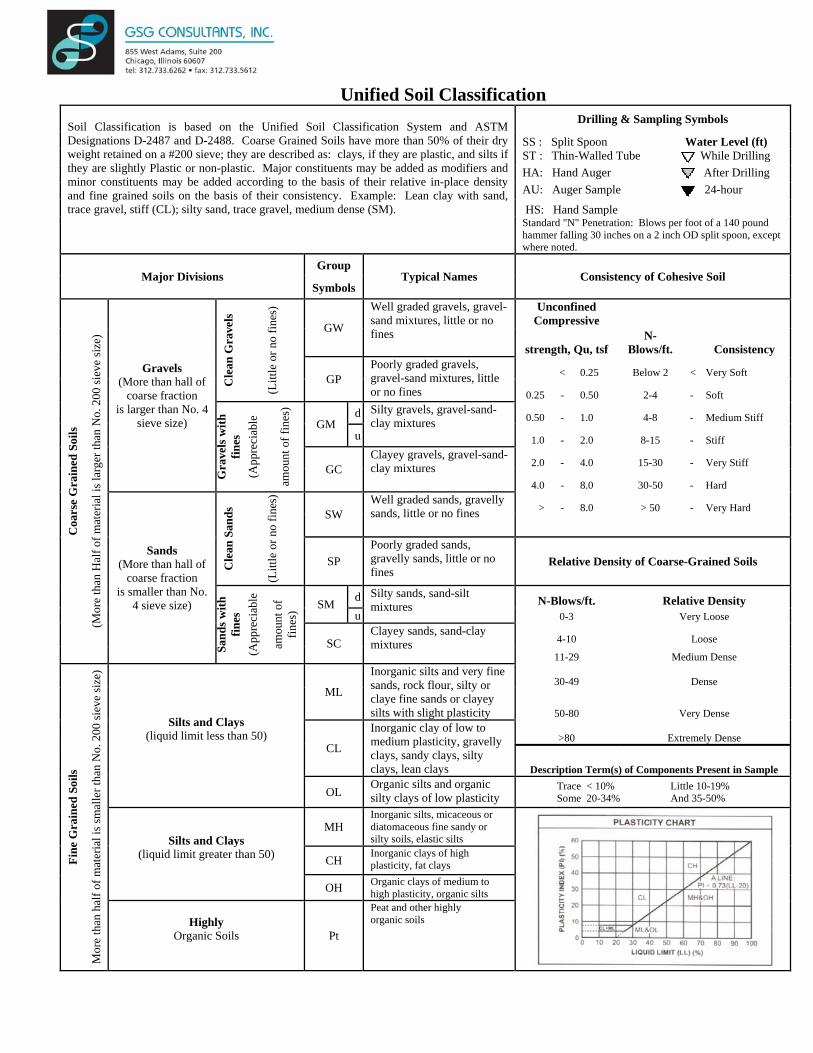
Unified Soil Classification Soil Classification is based on the Unified Soil Classification System and ASTM Designations D-2487 and D-2488. Coarse Grained Soils have more than 50% of their dry weight retained on a #200 sieve; they are described as: clays, if they are plastic, and silts if they are slightly Plastic or non-plastic. Major constituents may be added as modifiers and minor constituents may be added according to the basis of their relative in-place density and fine grained soils on the basis of their consistency. Example: Lean clay with sand, trace gravel, stiff (CL); silty sand, trace gravel, medium dense (SM).
Drilling & Sampling Symbols
SS : Split Spoon Water Level (ft) ST : Thin-Walled Tube While Drilling HA: Hand Auger After Drilling AU: Auger Sample 24-hour
HS: Hand Sample Standard "N" Penetration: Blows per foot of a 140 pound hammer falling 30 inches on a 2 inch OD split spoon, except where noted.
Major Divisions Group
Typical Names Consistency of Cohesive Soil Symbols
Coa
rse
Gra
ined
Soi
ls
(Mor
e th
an H
alf o
f mat
eria
l is l
arge
r tha
n N
o. 2
00 si
eve
size
)
Gravels (More than hall of
coarse fraction is larger than No. 4
sieve size)
Cle
an G
rave
ls
(Litt
le o
r no
fines
)
GW
Well graded gravels, gravel- sand mixtures, little or no fines
Unconfined Compressive
strength, Qu, tsf N-
Blows/ft. Consistency
GP Poorly graded gravels, gravel-sand mixtures, little or no fines
< 0.25 Below 2 < Very Soft
0.25 - 0.50 2-4 - Soft
Gra
vels
with
fin
es
(App
reci
able
amou
nt o
f fin
es)
GM d Silty gravels, gravel-sand-
clay mixtures 0.50 - 1.0 4-8 - Medium Stiff
u 1.0 - 2.0 8-15 - Stiff
GC Clayey gravels, gravel-sand- clay mixtures 2.0 - 4.0 15-30 - Very Stiff
4.0 - 8.0 30-50 - Hard
Sands (More than hall of
coarse fraction is smaller than No.
4 sieve size)
Cle
an S
ands
(Litt
le o
r no
fines
)
SW Well graded sands, gravelly sands, little or no fines > - 8.0 > 50 - Very Hard
SP Poorly graded sands, gravelly sands, little or no fines
Relative Density of Coarse-Grained Soils
Sand
s with
fin
es
(App
reci
able
amou
nt o
f fin
es) SM d Silty sands, sand-silt
mixtures N-Blows/ft. Relative Density u 0-3 Very Loose
SC Clayey sands, sand-clay mixtures 4-10 Loose
11-29 Medium Dense
Fine
Gra
ined
Soi
ls
Mor
e th
an h
alf o
f mat
eria
l is s
mal
ler t
han
No.
200
siev
e si
ze)
Silts and Clays
(liquid limit less than 50)
ML
Inorganic silts and very fine sands, rock flour, silty or claye fine sands or clayey silts with slight plasticity
30-49 Dense
50-80 Very Dense
CL
Inorganic clay of low to medium plasticity, gravelly clays, sandy clays, silty clays, lean clays
>80 Extremely Dense
Description Term(s) of Components Present in Sample
OL Organic silts and organic silty clays of low plasticity
Trace < 10% Little 10-19% Some 20-34% And 35-50%
Silts and Clays
(liquid limit greater than 50)
MH Inorganic silts, micaceous or diatomaceous fine sandy or silty soils, elastic silts
CH Inorganic clays of high plasticity, fat clays
OH Organic clays of medium to high plasticity, organic silts
Highly
Organic Soils
Pt
Peat and other highly organic soils

APPENDIX D
SLOPE STABILITY ANALYSES EXHIBITS

7.87.8
W
7.87.8
Material Name Color Unit Weight(kN/m3) Strength Type Cohesion
(kPa)Phi(deg)
New Engineered Granular Fill 125 Mohr‐Coulomb 0 32
Brown Clay 130 Mohr‐Coulomb 1500 0
Brown and Gray Sand with Gravel Fill 130 Mohr‐Coulomb 0 32
Brown and Gray Silty Clay 136 Mohr‐Coulomb 3300 0
Gray Silty Clay 134 Mohr‐Coulomb 2900 0
Timber 120 Infinite strength
Safety Factor0.00.30.50.81.01.31.51.82.02.32.52.83.03.33.53.84.04.34.54.85.05.35.55.86.0+
3020
100
-10
-30 -20 -10 0 10 20 30
Analysis Description Exhibit 1 - Eola Road - Circular Short TermCompany GSG ConsultantsScale 1:287Drawn By CDJFile Name Eola Road - Circular Short Term.slimDate 4/10/2018, 11:41:51 AM
Project
DuPage County Retaining Wall Repairs
SLIDEINTERPRET 7.010

2.32.3
W
2.32.3
Material Name Color Unit Weight(kN/m3) Strength Type Cohesion
(kPa)Phi(deg)
New Engineered Granular Fill 125 Mohr‐Coulomb 0 32
Brown Clay Drained 130 Mohr‐Coulomb 100 28
Brown and Gray Sand with Gravel Fill Drained 130 Mohr‐Coulomb 0 32
Brown and Gray Silty Clay Drained 136 Mohr‐Coulomb 125 28
Gray Silty Clay Drained 134 Mohr‐Coulomb 100 28
Timber 120 Infinite strength
Safety Factor0.00.30.50.81.01.31.51.82.02.32.52.83.03.33.53.84.04.34.54.85.05.35.55.86.0+
2010
0-10
-30 -20 -10 0 10 20 30
Analysis Description Exhibit 2 - Eola Road - Circular Long TermCompany GSG ConsultantsScale 1:278Drawn By CDJFile Name Eola Road - Circular Long Term.slimDate 4/10/2018, 11:41:51 AM
Project
DuPage County Retaining Wall Repairs
SLIDEINTERPRET 7.010

2.12.1
W
2.12.1
Material Name Color Unit Weight(kN/m3) Strength Type Cohesion
(kPa)Phi(deg)
Phi b(deg)
Air Entry(kPa)
New Engineered Granular Fill 125 Mohr‐Coulomb 0 32 0 0
Brown Clay 130 Mohr‐Coulomb 1500 0 0 0
Brown Sand with Gravel Fill 130 Mohr‐Coulomb 0 30 0 0
Brown Sand with Gravel 134 Mohr‐Coulomb 0 38 0 0
Concrete 120 Infinite strength 0 0
Safety Factor0.00.30.50.81.01.31.51.82.02.32.52.83.03.33.53.84.04.34.54.85.05.35.55.86.0+
100
-10
-20
-20 -10 0 10 20 30
Analysis Description Exhibit 3 - Winfield Road - Circular Short TermCompany GSG ConsultantsScale 1:250Drawn By CDJFile Name Winfield Road - Circular Short Term r1.slimDate 4/9/2018, 12:55:01 PM
Project
DuPage County Retaining Wall Repairs
SLIDEINTERPRET 7.034
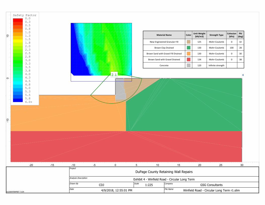
2.12.12.12.1
Material Name Color Unit Weight(kN/m3) Strength Type Cohesion
(kPa)Phi(deg)
New Engineered Granular Fill 125 Mohr‐Coulomb 0 32
Brown Clay Drained 130 Mohr‐Coulomb 100 28
Brown Sand with Gravel Fill Drained 130 Mohr‐Coulomb 0 30
Brown Sand with Gravel Drained 134 Mohr‐Coulomb 0 38
Concrete 120 Infinite strength
Safety Factor0.00.30.50.81.01.31.51.82.02.32.52.83.03.33.53.84.04.34.54.85.05.35.55.86.0+
100
-10
-20 -15 -10 -5 0 5 10 15 20 25 30
Analysis Description Exhibit 4 - Winfield Road - Circular Long TermCompany GSG ConsultantsScale 1:225Drawn By CDJFile Name Winfield Road - Circular Long Term r1.slimDate 4/9/2018, 12:55:01 PM
Project
DuPage County Retaining Wall Repairs
SLIDEINTERPRET 7.034

9.59.5
W
9.59.5
Material Name Color Unit Weight(kN/m3) Strength Type Cohesion
(kPa)Phi(deg)
Black and Gray Clay Fill 137 Mohr‐Coulomb 3500 0
Brown and Gray Silty Clay 138 Mohr‐Coulomb 3700 0
Brown and Gray Sand with Gravel 136 Mohr‐Coulomb 0 39
Concrete 120 Infinite strength
New Engineered Cohesive Fill 128 Mohr‐Coulomb 1500 0
New Engineered Granular Fil 125 Mohr‐Coulomb 0 32
Safety Factor0.00.30.50.81.01.31.51.82.02.32.52.83.03.33.53.84.04.34.54.85.05.35.55.86.0+
2010
0-10
-20
-40 -30 -20 -10 0 10 20 30
Analysis Description Exhibit 5 - Yackley Ave - Circular Short TermCompany GSG ConsultantsScale 1:301Drawn By CDJFile Name Yackley Ave - Circular Short Term.slimDate 4/9/2018, 12:55:01 PM
Project
DuPage County Retaining Wall Repairs
SLIDEINTERPRET 7.034

3.53.5
W
3.53.5
Material Name Color Unit Weight(kN/m3)
Strength Type Cohesion(kPa)
Phi(deg)
Black and Gray Clay Fill Drained 137 Mohr‐Coulomb 125 28
Brown and Gray Silty Clay Drained 138 Mohr‐Coulomb 125 32
Brown and Gray Sand with Gravel Drained 136 Mohr‐Coulomb 0 39
Concrete 120 Infinite strength
New Engineered Cohesive Fill 128 Mohr‐Coulomb 1500 0
New Engineered Granular Fil 125 Mohr‐Coulomb 0 32
Safety Factor0.00.30.50.81.01.31.51.82.02.32.52.83.03.33.53.84.04.34.54.85.05.35.55.86.0+
2010
0-10
-20
-40 -30 -20 -10 0 10 20 30
Analysis Description Exhibit 6 - Yackley Ave - Circular Long TermCompany GSG ConsultantsScale 1:300Drawn By CDJFile Name Yackley Ave - Circular Long Term.slimDate 4/9/2018, 12:55:01 PM
Project
DuPage County Retaining Wall Repairs
SLIDEINTERPRET 7.034

25.525.5
W
250.00 lbs/ft2
25.525.5
Material Name Color Unit Weight(lbs/ 3) Strength Type Cohesion
(psf)Phi(deg)
New Engineered Granular Fill 125 Mohr‐Coulomb 0 32
Black and Brown Clay Fill 130 Mohr‐Coulomb 2500 0
Brown and Gray Silty Clay 135 Mohr‐Coulomb 2800 0
Gray Silty Clay 133 Mohr‐Coulomb 2500 0
Safety Factor0.00.30.50.81.01.31.51.82.02.32.52.83.03.33.53.84.04.34.54.85.05.35.55.86.0+
2010
0-1
0
-30 -20 -10 0 10 20 30
Analysis Description Exhibit 7 - 55th Street - Circular Short TermCompany GSG ConsultantsScale 1:79Drawn By CDJFile Name 55th Street - Circular Short Term.slimDate 4/6/2018, 9:15:43 AM
Project
DuPage County Retaining Wall Repairs
SLIDEINTERPRET 7.010

5.15.1
W
250.00 lbs/ft2
5.15.1
Material Name Color Unit Weight(lbs/ 3) Strength Type Cohesion
(psf)Phi(deg)
New Engineered Granular Fill 125 Mohr‐Coulomb 0 32
Black and Brown Clay Fill Drained 130 Mohr‐Coulomb 100 28
Brown and Gray Silty Clay Drained 135 Mohr‐Coulomb 100 28
Gray Silty Clay Drained 133 Mohr‐Coulomb 100 28
Safety Factor0.00.30.50.81.01.31.51.82.02.32.52.83.03.33.53.84.04.34.54.85.05.35.55.86.0+
2010
0-1
0
-30 -20 -10 0 10 20 30
Analysis Description Exhibit 8 - 55th Street - Circular Long TermCompany GSG ConsultantsScale 1:82Drawn By CDJFile Name 55th Street - Circular Long Term.slimDate 4/6/2018, 9:15:43 AM
Project
DuPage County Retaining Wall Repairs
SLIDEINTERPRET 7.010