Embed Size (px)
Citation preview
AIAA-2001-1263
STRUCTURAL DYNAMICS EXPERIMENTAL ACTIVITIES IN
ULTRA-LIGHTWEIGHT AND INFLATABLE SPACE STRUCTURES
Richard S. Pappa
Structural Dynamics Branch
NASA Langley Research Center
Hampton, VA 23681
John O. Lassiter
Structural and Dynamics Test Group
NASA Marshall Space Flight Center
Huntsville, AL 35812
Brian P. Ross
Structural Dynamics Test Engineering
NASA Goddard Space Flight Center
Greenbelt, MD 20771
ABSTRACT
This paper reports recently completed structural
dynamics experimental activities with new ultra-
lightweight and inflatable space structures (a.k.a.,
"Gossamer" spacecraft) at NASA Langley Research
Center, NASA Marshall Space Flight Center, and
NASA Goddard Space Flight Center. Nine aspects of
this work are covered, as follows: 1) inflated, rigidized
tubes, 2) active control experiments, 3) photo-
grammetry, 4) laser vibrometry, 5) modal tests of
inflatable structures, 6) in-vacuum modal tests, 7)
tensioned membranes, 8) deployment tests, and 9)
flight experiment support. Structural dynamics will
play a major role in the design and eventual in-space
deployment and performance of Gossamer spacecraft,
and experimental R&D work such as this is required
now to validate new analytical prediction methods. The
activities discussed in the paper are pathfinder
accomplishments, conducted on unique components
and prototypes of future spacecraft systems.
INTRODUCTION
• Solar sails of 100m or larger in size with areal
densities of less than 2 g/m _
• Orbital transfer vehicles with large inflatable
concentrators for solar thermal propulsion
• Next-generation space telescopes with large
membrane sunshields forpassive cooling
• Space solar power collectors and transmitters thatare hundreds or even thousands of meters in size
• Inflatable habitats for the Inter'national Space
Station or future lunar or planetary exploration
A predominant design factor for future ultra-
lightweight space structures is their dynamic response
to applied loads, which is correspondingly larger than
for heavier structures. Therefore, structural dynamics
will play a major role in the development and eventual
in-space deployment and performance of these systems.
Structural dynamic analytical prediction methods for
Gossamer spacecraft are mostly unproven. 4' 5 Ground
and flight tests of prototype hardware are required as
soon as possible to validate the accuracy and
sufficiency of these new analytical methods.
Initial experimental work along these lines has
NASA is focusing renewed attention on the topic ................. recently at the Langley Research
of large, ultra-lightweight space structures, also known
as "Gossamer" spacecraft, t' 2 New materials and new
structural concepts including inflatables offer the
possibility of creating space structures that are orders of
magnitude larger and/or lighter than existing ones. 3
This technology can enable many new classes of
missions within the next 5-30 years, such as:
• Space observatories with collectors of 30m or larger
in size with sub-millimeter surface accuracy
This paper is declared a work of the U.S. Government and is not
subject to copyright protection in the United States.
Center (LaRC), the Marshall Space Flight Center
(MSFC), and the Goddard Space Flight Center (GSFC),
and this paper summarizes these activities. Due to the
uniqueness of the structures being tested, experiments
conducted to date generally have required as much
effort in developing the test methods themselves as in
acquiring the specific test results. Test procedures used
for traditional aerospace structures are mostly not
applicable. Therefore, the results presented in this paper
are pathfinder accomplishments, to be undoubtedly
followed by improved experimental methods and
facilities in the months and years ahead.
1
American Institute of Aeronautics and Astronautics
https://ntrs.nasa.gov/search.jsp?R=20010027549 2020-05-02T19:26:45+00:00Z

This paperdiscussesninerecentexamplesof
structural dynamics experimental activities with
Gossamer-related structures. Three topics come from
each contributing Center, as follows:
Langley Research Center (LaRC)
1. Inflated, Rigidized Tubes
2. Active Control Experiments
3. Photogrammetry
Marshall Space Flight Center (MSFC)
4. Laser Vibrometry5. Modal Tests of Inflatable Structures
6. In-Vacuum Modal Tests
Goddard Space Flight Center (GSFC)
7. Tensioned Membranes
8. Deployment Tests
9. Flight Experiment Support
There is considerable synergism and overlap
between these nine topics, and related efforts in several
areas are underway at more than one Center.
STRUCTURAL DYNAMICS
EXPERIMENTAL ACTIVITIES
1. Inflated, Rigidized Tubes (/_aRC)
The Langley Research Center, in cooperation with
the Jet Propulsion Laboratory (JPL) and the
Department of Defense (DoD), is developing a databaseof measured structural characteristics of inflated,
rigidized tubes suitable for space application. These
tubes can serve as primary load-bearing members for
many Gossamer concepts, such as large space solar
power satellites. 6 LaRC will perform static load tests on
each tube to measure its axial stiffness, bending
stiffness, and buckling resistance. 7 Most test articles for
the program have a length-to-diameter ratio (LID) of
approximately 10, with diameters of approximately 4,
5, or 6 inches. Two long tubes with an L/D of 100 (6-
in. diameter) are also available for testing for
comparison with short tubes of similar construction.
To supplement the static test results, vibration tests
will also be conducted on some of the tubes. Figure
I(a) shows a set of eight 4-in.-diameter inflated,
rigidized, composite tubes that were tested in a
cantilevered configuration as shown. Figures I(b)-(d)
show the approach used for axial, bending, and
torsional vibration tests with tip impact excitation and
two miniature aecelerometers. The main objective of
the tests is to calculate the effective Young's Modulus
(E) and Shear Modulus (G) of each tube from the
experimental natural frequencies. To validate the
testing and data analysis procedures, several aluminum
"calibration specimens" (with known E and G) were
also tested. Figure l(a) also shows one of the
calibration specimens. In each test, data were acquired
with varying amounts of added tip mass ranging from
10 to 500 grams. Figure I(b) shows an example of an
added mass. Acquiring data sets with varying tip mass
increased the confidence in the calculated structural
properties.
This test program will measure structural
parameters for many leading types of inflated, rigidized
tubes. It will examine the effects of rigidization
technique, manufacturing procedure, and the method of
packaging for launch, all of which can significantly
affect structural performance. The resulting database
will provide validated structural parameters for
Gossamer spacecraft designers. In the future, the
program will expand to include inflatable, rigidizable
trusses, which will be tested in a similar manner.
2. Active Control Experiments (LaRC)
Figure 2 shows a proof-of-concept active vibration
control experiment conducted at LaRC. The objective
was to demonstrate that the damping of the first
bending mode of the structure could be increased to at
least 5% of critical damping using embedded
piezoactuators. The test article is the lower, dark-
colored tube seen in Figure 2(a). It is a 3-ft-long, 4-
inch-diameter, inflated, rigidized composite tube with
embedded actuators. Prior to inflation and curing, it
was flattened and then z-folded, like an accordion, as
tubes of this type can be folded for launch into space. A
3-ft piece of white plastic pipe is attached to the top of
the composite tube as a dummy mass, lowering the
bending frequency to the desired value of 10 Hz to
simulate the fundamental vibration frequency of a
proposed mission.
Four 2.25 in. x 3.375 in. piezoelectric patch
actuators are embedded in the wall of the composite
tube near its base at 90-degree intervals around the
circumference. These piezoactuators were developed
2
American Institute of Aeronautics and Astronautics

in-house and are called Macro Fiber Composite (MFC)
actuators, s They use the d_ mode of the piezoelectric
material to achieve an operational efficiency that is
about twice as high as more commonly used d3_-mode
piezoelectric devices (500 microstrain/kV/mm vs. 250
microstrain/kV/mm). Additional features of the MFC
actuator are its high maximum free strain level (-2000
microstrain peak-to-peak), directional strain capability,
and high flexibility and durability.
For active vibration control, the experiment used a
basic analog feedback circuit with gain adjustment. The
feedback signal is the fore-aft vibration velocity of the
tube measured with a laser vibrometer. Only the front
and rear piezoactuators are used, and they are wired
out-of-phase electrically to work together in bending.
Figure 2(b) shows the open-loop versus closed-loop
free-decay vibration response of the tip of the beam.
Without control (open loop), the natural damping of the
first bending mode is 0.4%, corresponding to a free-
decay vibration period greater than 10 seconds. With
control (closed loop), the damping increases to 8%, a
factor of 20 increase, corresponding to a free-decay
vibration period of only 1 second. Future experiments
of this type will use digital controllers, which will
enable even higher damping levels to be obtained.
Follow-on work is underway to also examine the
effectiveness of piezoactuators for static shape
adjustment of Gossamer structures. In particular, it may
be possible using these devices to remove unwanted
shape distortions of a structure before it is rigidized in
space. Work is also underway on better defining
actuator performance in a simulated space environment.
Although piezoelectric patch actuators have performed
with good success in several previous aeronautics
applications, e.g., to twist helicopter blades or reduce
buffet loads in aircraft tails, 9 the harsh space
environment poses new design and implementation
challenges for their use.
3. Photogrammetry (LaRC)
Photogrammetry is the science of calculating the
three-dimensional coordinates of physical objects using
photographs. _° it is a leading candidate technology for
measuring the static shape and/or motion of future
ultra-lightweight and inflatable space structures. It
offers the simplicity of taking photographs coupled
with good to excellent measurement precision. With
time series of images (typically from video cameras), it
is usually referred to as "videogrammetry" or
"videometrics" and is used in many diverse engineering
applications, such as to measure the deformation of
aircraft wings in wind tunnels. _
Research is underway at LaRC to begin addressing
the technical challenges and requirements of
photogrammetry and videogrammetry for Gossamer
structures. Techniques will be developed to measure
structures in both air and vacuum environments in one
or more of the following three Conditions, listed
according to the anticipated level of difficulty:
• Stationary (least difficult)
• Vibrating
• Deploying
Figure 3(a) shows one of the test articles recently
used in this research. It is a 5m-diameter inflatable
parabolic reflector attached with thin cords at its
perimeter to an inflatable Kapton torus. The total
weight of the structure is approximately 4 kg (8.8 lbs).
SRS Technologies of Huntsville, AL manufactured thisstructure for NASA in 1996 under a research and
technology development contract. In space, this
concept can serve as either a radio-frequency antenna
or as a solar concentrator for electrical power
generation and/or propulsion. The photograph shows
the rear, convex surface of the reflector, which is
covered with more than 500 retro-reflective targets for
photogrammetry. The other side of the antenna (not
visible) has three struts arranged in a tripod
configuration for holding the antenna feed. In this
work, the struts attach to a stiff support frame.
The static shape of the reflector was measured in
the initial investigation. There were two main research
objectives: 1) Determine the photogrammetric
measurement precision obtained using multiple
consumer-grade digital cameras and 2) Gain experience
with new commercial photogrammetry software
packages, specifically PhotoModeler Pro from Eos
Systems, Inc. Photographs were taken from four
different positions using four separate Kodak DC290
(2.l-megapixel) digital cameras. Using four different
cameras simulated the future objective of measuring
vibrating or deploying Gossamer structures with
multiple, time-synchronized cameras. To minimize air
currents, the tests were conducted (at room temperature
3
American Institute of Aeronautics and Astronautics

andpressureconditions)insidea16m-diametervacuumchamberat LaRC. Details of this project aredocumented elsewhere. _2
Figure 3(b) shows the final results of the
photogrammetric calculations. The software calculated
this dense wireframe model using the photo-
a vibrometer provides is noncontacting response
measurement. This approach avoids the undesirable
mass-loading effects of a traditional array of
accelerometers. Even the added mass and stiffness of
accelerometer cables can appreciably affect the
dynamic response of an inflatable structure. This
section discusses various experimental methods
grammetrically obtained 3D points.
squares analysis, the best parabolic surface representing
the complete set of 521 measurement points was
calculated. The focal length of this parabolic surface
was 120.09 inches, which compared closely with the
design focal length of 120 inches. The root-mean-
square deviation over the entire 5m-diameter reflector
surface from an ideal parabolic shape was
approximately 1.5 millimeters.
Using a least- developed and used at MSFC over more than three
years of testing ultra-lightweight and inflatable space
structures with a laser vibrometer system.
Figure 3(c) shows the corresponding measurement
precisions of the calculated 3D points (at 95%
probability). This important information is a by-product
of the photogrammetric calculations with the Bundle
adjustment method. The overall measurement precision
is summarized by the mean values for each direction.
(X is horizontal, Y is vertical, and Z is longitudinal.)
The cameras photographed a 6.5m test article
(including the torus); therefore these average precision
values correspond to 1:28000 (1 part in 28000) in the X
direction, 1:14000 in the Y direction, and 1:5000 in the
Z direction. These are moderate photogrammetric
precision levels, but would be acceptable for many uses
of the data. Additional tests conducted on the 5m
antenna have shown that these precision values can be
improved, as expected, by increasing the number ofcamera locations and/or the resolution of the cameras.
Future experiments at LaRC will build upon these
experiences gained in measuring the static shape of the
5m inflatable antenna and wiI1 progress to also
Figure 4(a) shows one laser position used in arecent modal test of a 5m inflatable antenna/solar
concentrator at MSFCJ 4 This structure is the same one
discussed in the previous section of the paper. (It was
moved to LaRC following this modal test.) Note that
the vibrometer can operate at long distances from the
test article. Additional measurements were also made
with the vibrometer at other locations relative to the
structure. Figure 4(b) shows how the structure was
excited with an electrodynamic shaker attached to one
of the three struts. Because the inflatable portion of the
structure is so lightweight (about 9 lbs), a dynamicforce level of less than 1 lb is sufficient to excite
vibrations that are easily measured with the vibrometer.
Figure 4(c) shows one of the mode shapes identified in
the test.
The Ometron vibrometer system can be operated
remotely via a serial computer interface. This capability
was required in the modal test of an inflatable structurelocated inside a vacuum chamber. The vibrometer
cannot operate in vacuum and had to be outside the
chamber. At this facility, only one porthole was
available to view the structure from outside. This
porthole was in a very inaccessible location. The
solution was to place only the vibrometer and a
measuring vibrating and/or deploying structures.
4. Laser Vibrometry (MSFC)
A laser vibrometer is a sophisticated instrument
that measures the surface vibration velocity in the
direction of the laser beam only at any point on a
structure that the laser illuminates. Laser vibrometry is
a mature, though costly, measurement technologyJ 3
The vibrometer used at MSFC is an Ometron scanning
vibrometer system, which can scan from point to point
on the structure by moving internal mirrors under
computer control. The obvious and primary benefit that
minimum amount of test hardware near the porthole
and to control the vibrometer with a personal computer
located about 20 feet away via the serial interface. All
inflatable structure dynamic tests have used this
computer interface, including those that had norestrictions on where the vibrometer could be located.
All of the inflatable structures tested at MSFC have
been primarily constructed of thin-film materials that
are transparent. A laser vibrometer must detect some
reflected laser light from the structure in order to make
the measurement, which will not occur if it is too
transparent. This can also occur if the surface is too
4
American Institute of Aeronautics and Astronautics

reflective, in which case all non-perpendicular laser
beams deflect entirely away from their source. To
circumvent this problem, retro-reflective targets have
been used in every modal test. A small section of
adhesive retro-reflective tape (usually 0.5 sq. in. or
less) is attached at each response point. Such small
pieces of tape, which are only a few mils thick, have
little effect on the structural dynamic response
characteristics. They have been used for tests with up to
60 response points. Small pieces of retro-reflective tape
have also often been placed perpendicular to the
surface to permit measurements to be made in
directions parallel to the surface of the structure. These
perpendicular pieces of tape serve as "corner cubes." Of
course, consideration must always be given to potential
damage of an ultra-lightweight or inflatable structure
when removing any type of surface preparation,
especially for thin membranes.
For testing small subcomponents of inflatables or
ultra-thin membranes, the application of any reflective
the direction of the coordinate axis. The other method
is to position the laser vibrometer a long distance from
the structure and aligned in the axis direction. The
difficulty here is that the test requires a vacant facility
substantially larger than the test article. Also, at long
distances it can be difficult to see the measurement
targets at some locations. Another practical problem
that occurs in many tests it that it is difficult to locate
the vibrometer along one or more of the coordinate
axis. For example, in the 5m antenna modal test shown
in Figure 4, it was impractical to locate the vibrometer
high above the structure to measure the vertical
............. of vibration.
To allow three-dimensional velocity measurements
to be obtained more easily and accurately with the
vibrometer, MSFC recently purchased the LMS
International CADA-X Laser Vibrometer Interface
(LVI). This package integrates with an existing CADA-
X suite of software that MSFC uses for large modal
tests. The LVI controls the scanning of the laser and
tape as a surface preparation could unacceptably alter coupled with the Fourier Monitor module of CADA-X,
the structural response. Other methods may need to be it calculates frequency response functions (FRFs). To
investigated to obtain adequate laser return signals. For
example, to test a l-m s ultra-thin membrane, reflective
tape could be avoided completely if the test article were
constructed of an opaque material (a diffuse white
surface is best). Selecting a specific type of membrane
material to simplify making the vibration measurements
may be feasible in certain research tests. A diffuse
sprayed-on paint coating could also possibly be used. In
this case, only a small area near each response point
would be sprayed by carefully masking the surrounding
area.
obtain FRFs along each axis using the LVI, vibrometer
measurements must be acquired for the same set of
response points using three or more non-coplanarvibrometer locations. The LVI uses these datasets and
least-squares analysis to calculate FRFs corresponding
to each coordinate axis. Of course, if the measurements
do not contain sufficient information in one of the axis
directions, then the resulting data for that axis may be
noisy.
5. Modal Tests of Inflatable Structures (MSFC)
Another practical factor to consider is MSFC has conducted modal tests of five full-scale
measurement errors that occur when the laser beam is inflatable structures ranging in size from approximately
not aligned with a coordinate axis of the structure.
Recall that the vibrometer measures only the
component of velocity in the direction of the laser
beam. Positioning the vibrometer to be parallel with an
axis for every response point is impractical for large
structures with numerous points. These off-axis errors
have been addressed using two different methods. The
first method approximates the vibration component in
the desired axis by dividing the measured vibrometer
• response data by the appropriate direction cosine. This
is a good approximation if the angle between the laser
beam and the coordinate axis is relatively small or if the
motion at the measurement point is predominately in
6 to 21 ft, as shown in Figure 5. All of the structures
were torus-supported concentrators with application to
solar thermal propulsion systems or radio
transmitter/receiver systems (antennas). These modal
tests have been fully documented in test reports and
several have been described in technical papers and in a
recently published book on Gossamer spacecraft. _5"_
This section discusses some of the experiences and
lessons learned in conducting the modal tests of these
unique inflatable structures.
Both free-free and fixed-base boundary conditions
have been used. In free-free tests, low-stiffness springs
5
American Institute of Aeronautics and Astronautics
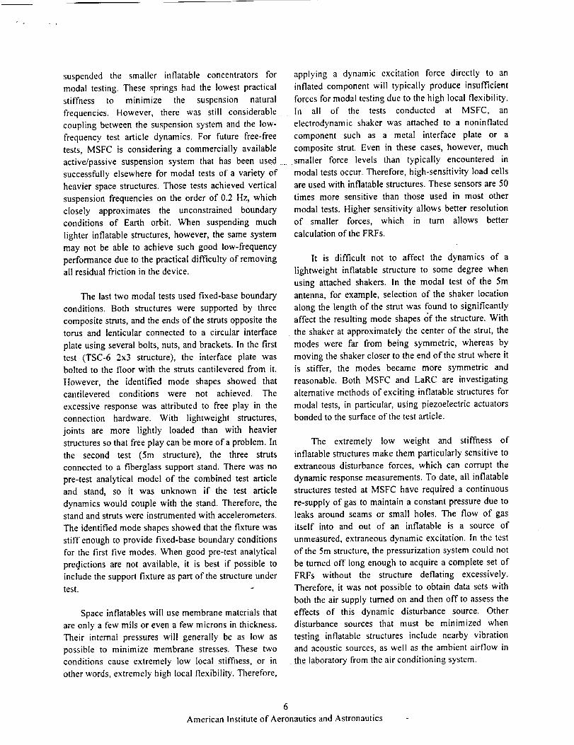
suspendedthe smallerinflatableconcentratorsfor applyinga dynamicexcitationforcedirectlyto anmodaltesting.Thesespringshadthelowestpractical inflatedcomponentwill typicallyproduceinsufficientstiffness to minimize the suspensionnaturalfrequencies.However,therewasstill considerablecouplingbetweenthesuspensionsystemandthelow-frequencytestarticledynamics.For futurefree-freetests,MSFCis consideringa commerciallyavailableactive/passivesuspensionsystemthathasbeenusedsuccessfullyelsewhereformodaltestsof avarietyofheavierspacestructures.Those tests achieved vertical
suspension frequencies on the order of 0.2 Hz, which
closely approximates the unconstrained boundary
conditions of Earth orbit. When suspending much
lighter inflatable structures, however, the same system
may not be able to achieve such good low-frequency
performance due to the practical difficulty of removingall residual friction in the device.
The last two modal tests used fixed-base boundary
conditions. Both structures were supported by three
composite struts, and the ends of the struts opposite thetorus and lenticular connected to a circular interface
plate using several bolts, nuts, and brackets. In the first
test (TSC-6 2x3 structure), the interface plate was
bolted to the floor with the struts cantilevered from it.
However, the identified mode shapes showed that
cantilevered conditions were not achieved. The
excessive response was attributed to free play in the
connection hardware. With lightweight structures,
joints are more lightly loaded than with heavier
structures so that free play can be more of a problem. In
the second test (5m structure), the three struts
connected to a fiberglass support stand. There was no
pre-test analytical model of the combined test article
and stand, so it was unknown if the test article
dynamics would couple with the stand. Therefore, the
stand and struts were instrumented with accelerometers.
The identified mode shapes showed that the fixture was
stiff enough to provide fixed-base boundary conditions
for the first five modes. When good pre-test analytical
predictions are not available, it is best if possible to
include the support fixture as part of the structure under
test.
Space inflatables will use membrane materials that
are only a few mils or even a few microns in thickness.
Their internal pressures will generally be as low as
possible to minimize membrane stresses. These two
conditions cause extremely low local stiffness, or in
other words, extremely high local flexibility. Therefore,
forces for modal testing due to the high local flexibility.
In all of the tests conducted at MSFC, an
electrodynamic shaker was attached to a noninflated
component such as a metal interface plate or a
composite strut. Even in these cases, however, much
smaller force levels than typically encountered in
modal tests occur. Therefore, high-sensitivity load cells
are used with inflatable structures. These sensors are 50
times more sensitive than those used in most other
modal tests. Higher sensitivity allows better resolution
of smaller forces, which in turn allows better
calculation of the FRFs.
It is difficult not to affect the dynamics of a
lightweight inflatable structure to some degree when
using attached shakers. In the modal test of the 5m
antenna, for example, selection of the shaker location
along the length of the strut was found to significantly
affect the resulting mode shapes of the structure. With
the shaker at approximately the center of the strut, the
modes were far from being symmetric, whereas by
moving the shaker closer to the end of the strut where it
is stiffer, the modes became more symmetric and
reasonable. Both MSFC and LaRC are investigating
alternative methods of exciting inflatable structures for
modal tests, in particular, using piezoelectric actuators
bonded to the surface of the test article.
The extremely low weight and stiffness of
inflatable structures make them particularly sensitive to
extraneous disturbance forces, which can corrupt the
dynamic response measurements. To date, all inflatable
structures tested at MSFC have required a continuous
re-supply of gas to maintain a constant pressure due toleaks around seams or small holes. The flow of gas
itself into and out of an inflatable is a source of
unmeasured, extraneous dynamic excitation. In the test
of the 5m structure, the pressurization system could not
be turned off long enough to acquire a complete set of
FRFs without the structure deflating excessively.
Therefore, it was not possible to obtain data sets with
both the air supply turned on and then off to assess the
effects of this dynamic disturbance source. Otherdisturbance sources that must be minimized when
testing inflatable structures include nearby vibration
and acoustic sources, as well as the ambient airflow in
the laboratory from the air conditioning system.
6
American Institute of Aeronautics and Astronautics

The subject of nonlinear dynamic response is
another important factor for inflatable structures.
Considerable information exists on the analytical
aspects of the nonlinear structural response of
inflatables. However, there is not yet much
corroborating experimental data available. In early tests
at MSFC, sinusoidal sweeps were performed to identify
respectively. To acquire vibrometer data in more than
one axis, the test article needed to be rotated. The test
objectives also required data acquisition at three
different air pressure settings. Ideally, vibration data
should be measured in both orientations of the structure
holding the ambient pressure constant to ensure that the
measured vibration data in each axis corresponded to
those force levels that produced linear response of the exactly the same operating conditions of the chamber.
structure and the force levels of greater magnitudes that
produced nonlinear response. A significant result ofthese tests is the identification of the bifurcation
process, which is the splitting of one mode into two at
increasing force levels. _8Another result of these tests is
the conclusion that the response of an inflatable due to
any force level can be described as being chaoticallymodulated.
6. In-Vacuum Modal Tests (MSFC)
However, to rotate the structure required that the
chamber be depressurized, opened, then repressurized,
which took more than 12 hours to perform. To
substantially reduce the overall testing time at some
risk of data inconsistency, the decision was made to
conduct the vibration tests in the first structural
orientation at all three air pressures and then to repeat it
for the second structural orientation. Additional details
of this modal test of the Pathfinder 3 structure in the
XRCF vacuum chamber are available elsewhere. Is
It is well known that thin-film membranes
vibrating in air will have lower natural vibration
frequencies and higher damping values than when in
vacuum conditions. _9 It is therefore preferable, when
possible, to conduct modal vibration tests of these
structures in vacuum chambers to more closely
approximate the conditions of space. Of course,
Gossamer structures larger than approximately 15m in
size cannot be tested in vacuum because this is the size
limit of existing facilities. Tests in vacuum conditions
of larger structures can only occur using scale-model
test articles.
As mentioned previously, a laser vibrometer
cannot operate in vacuum so it must remain outside the
chamber. It is entirely possible, however, to obtain
good vibrometer measurements with the laser beam
passing through a glass porthole of the chamber. If the
chamber has multiple accessible portholes, the
vibrometer can be moved from location to location, and
the resulting data sets can be transformed into three-
dimensional structural response measurements at each
test point using the LMS LVI system discussed earlier.
Moving the vibrometer to multiple viewing ports
may not be possible with certain vacuum chambers. For
example, in the modal test of the Pathfinder 3 structure
conducted in vacuum in the large X-Ray Calibration
Facility (XRCF) at MSFC, only one porthole was
available. Figures 5(c) and 6 show this inflatable
structure inside the chamber and the test configuration,
There are several other potential problems
associated with conducting modal vibration tests in
vacuum chambers. For example, shaker overheating
could occur due to the lack of airflow that allows heat
dissipation. Difficulties in supporting a shaker either by
a fixture or a suspension device may also occur due to
lack of space in small chambers. The application of
piezoactuators for excitation of inflatable structures in
dynamic tests will possibly eliminate this problem. At
vacuum conditions, extraneous acoustic excitation will
not occur due to the lack of air. However, some form of
isolation may be required with ultra-lightweight
structures to eliminate any unwanted excitation from
structure-borne vibration that could come from vacuum
pumps or other chamber machinery. Cleanliness and
outgassing concerns are also often important when
conducting tests in these facilities.
7. Tensioned Membranes (GSFC)
During the past two years, the Goddard Space
Flight Center conducted two modal tests on a one-
tenth-scale model of the Next Generation Space
Telescope (NGST) sunshield to support structural
analytical model validation. Because the sunshield
surface is thin membrane material, the tests were
conducted in vacuum conditions to avoid the effects of
air on the membranes. This was the first time that
GSFC has conducted tests of this type. Many lessons
were learned during these two modal tests that are
applicable to future testing of membrane structures.
7
American Institute of Aeronautics and Astronautics
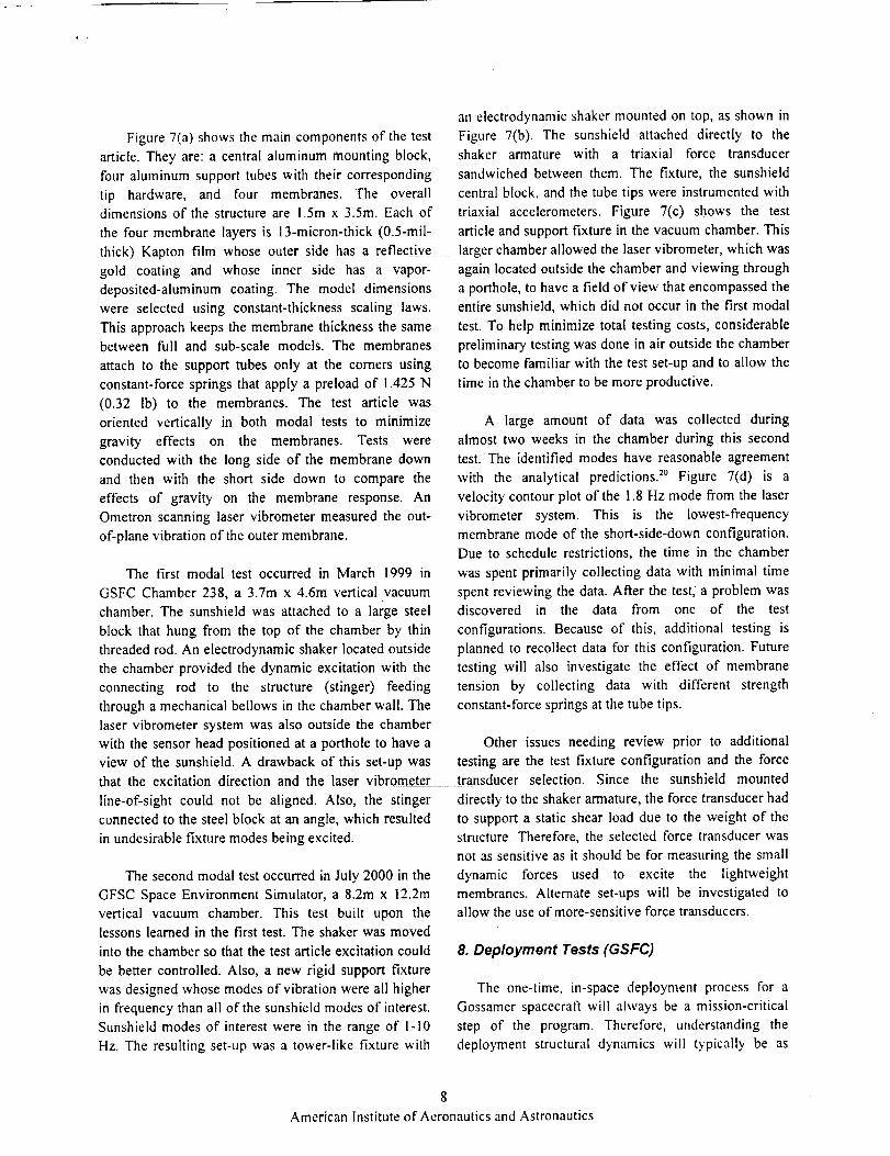
Figure7(a)shows the main components of the test
article. They are: a central aluminum mounting block,
four aluminum support tubes with their corresponding
tip hardware, and four membranes. The overall
dimensions of the structure are 1.5m x 3.5m. Each of
the four membrane layers is 13-micron-thick (0.5-rail-
thick) Kapton film whose outer side has a reflective
gold coating and whose inner side has a vapor-
deposited-aluminum coating. The model dimensions
were selected using constant-thickness scaling laws.
This approach keeps the membrane thickness the same
between full and sub-scale models. The membranes
attach to the support tubes only at the corners using
constant-force springs that apply a preload of 1.425 N
(0.32 lb) to the membranes. The test article was
oriented vertically in both modal tests to minimize
gravity effects on the membranes. Tests were
conducted with the long side of the membrane down
and then with the short side down to compare the
effects of gravity on the membrane response. An
Ometron scanning laser vibrometer measured the out-
of-plane vibration of the outer membrane.
The first modal test occurred in March 1999 in
GSFC Chamber 238, a 3.7m x 4.6m vertical vacuum
chamber. The sunshield was attached to a large steel
block that hung from the top of the chamber by thin
threaded rod. An electrodynamic shaker located outside
the chamber provided the dynamic excitation with the
connecting rod to the structure (stinger) feeding
through a mechanical bellows in the chamber wall. The
laser vibrometer system was also outside the chamber
with the sensor head positioned at a porthole to have a
view of the sunshield. A drawback of this set-up was
an electrodynamic shaker mounted on top, as shown in
Figure 7(b). The sunshield attached directly to theshaker armature with a triaxial force transducer
sandwiched between them. The fixture, the sunshield
central block, and the tube tips were instrumented with
triaxial accelerometers. Figure 7(c) shows the test
article and support fixture in the vacuum chamber. This
larger chamber allowed the laser vibrometer, which was
again located outside the chamber and viewing through
a porthole, to have a field of view that encompassed the
entire sunshield, which did not occur in the first modal
test. To help minimize total testing costs, considerable
preliminary testing was done in air outside the chamber
to become familiar with the test set-up and to allow the
time in the chamber to be more productive.
A large amount of data was collected during
almost two weeks in the chamber during this second
test. The identified modes have reasonable agreement
with the analytical predictions. :° Figure 7(d) is a
velocity contour plot of the 1.8 Hz mode from the laser
vibrometer system. This is the lowest-frequency
membrane mode of the short-side-down configuration.
Due to schedule restrictions, the time in the chamber
was spent primarily collecting data with minimal time
spent reviewing the data. After the test, a problem wasdiscovered in the data from one of the test
configurations. Because of this, additional testing is
planned to recollect data for this configuration. Future
testing will also investigate the effect of membrane
tension by collecting data with different strength
constant-force springs at the tube tips.
Other issues needing review prior to additional
testing are the test fixture configuration and the force
that the excitation direction and the laser vibrometer transducer selection.
line-of-sight could not be aligned. Also, the stinger
connected to the steel block at an angle, which resulted
in undesirable fixture modes being excited.
The second modal test occurred in July 2000 in the
GFSC Space Environment Simulator, a 8.2m x 12.2m
vertical vacuum chamber. This test built upon the
lessons learned in the first test. The shaker was moved
into the chamber so that the test article excitation could
be better controlled. Also, a new rigid support fixture
was designed whose modes of vibration were all higher
in frequency than all of the sunshield modes of interesL
Sunshield modes of interest were in the range of 1-10
Hz. The resulting set-up was a tower-like fixture with
Since the sunshield mounted
directly to the shaker armature, the force transducer had
to support a static shear load due to the weight of the
structure. Therefore, the selected force transducer was
not as sensitive as it should be for measuring the small
dynamic forces used to excite the lightweight
membranes. Alternate set-ups will be investigated to
allow the use of more-sensitive force transducers.
8. Deployment Tests (GSFC)
The one-time, in-space deployment process for a
Gossamer spacecraft will always be a mission-critical
step of the program. Therefore, understanding the
deployment structural dynamics will typically be as
8
American Institute of Aeronautics and Astronautics

important, or even more important, than understanding
the post-deployment dynamic characteristics. In supportof the development of the Next Generation Space
Telescope CNGST) sunshield, which will be a large,
lightweight, multiple-membrane structure that deploys
from a folded-up launch configuration, GSFC
sponsored the design, manufacture, and ground
deployment test of a one-half-scale model of the
The longitudinal tubes were then pressurized and
deployed simultaneously. Lastly, the tubes were
depressurized. Over the course of the program, four
deployments were performed.
A major lesson learned from the deployments was
that the gravity effects were greater than anticipated.
Longitudinal tube deflection required a vertical
"strawman" concept. This section discusses the test suspension line at the center span of the tube, and
article and the deployment test, which was performed at
ILC Dover, Inc. Other participants in the program were
GSFC, JPL, and L'Garde, Inc. The ground test article
had the following specifications:
• One-half-scale model ofNGST strawman design
• 4 membranes, two on each side of the supports
• 2.5-cm separation between membranes at support
platform, increasing to 15.0 cm at the free edge
• Lowest natural frequency greater than 0.2 Hz.
• Boom material shall be aluminum laminate, and
membrane material shall be 0.5-mil Kapton HN
• Boom safety factor of 4 in Euler buckling
• 8-degree cant angle in the membrane ends
suspension lines were also added to prevent buckling in
the longitudinal tubes at the low inflation pressures.
The membranes tended to fall out of the folded stack
during the deployment and resulted in switching from
dispensing clips to a retainer dispensing design. There
was also a problem with static electricity attraction
between the membrane layers that was eliminated by
adding a static-charge dissipative coating to the
membranes, z_
9. Flight Experiment Support (GSFC)
Figure 9 shows the Inflatable Sunshield in Space
(ISIS) flight experiment, which GSFC and JPL have
Membrane wrinkling is not an issue as long as the been developing
membranes do not touch Unfortunately, the
The goals of the deployment test were to evaluate
the various characteristics of the deployment, such as
the unfolding behavior of the membranes, the
straightness and stiffness of the deployed booms, the
impulse forces that would be imparted to the spacecraft,
and the post-deployment system planarity. Also
important was the need to verify that the packaging and
deployment procedures would eliminate trapped gas
and the threat of puncture during deployment.
Figure 8 shows the ground test article in both a
partially deployed and then a fully deployed state.
Details of the packaging and deployment sequence of
the structure are as follows. The membranes were z-
" folded in the lateral direction first followed by the
longitudinal direction, secured with membrane retainer
clips, then placed into membrane enclosures on the
central container. The central container was mounted
on a rigid support stand. The inflatable tubes were then
attached to the Container and membranes. Weight-relief
lines were attached to both longitudinal tubes and the
upper lateral tube. The lateral tubes were then
pressurized and deployed simultaneously, after which
weight-relief lines were also added to the membranes.
during the past several years.
ISIS experiment was cancelled
recently, and all work has stopped. Nevertheless, the
research and development that occurred in planning and
designing this flight experiment is excellent
information concerning the issues that need to be
addressed in any future flight experiment with large
Gossamer structures. This section summarizes the ISIS
experiment and its structural-dynamics-related aspects.
The ISIS test article is a 1/3-scale model of the
GSFC strawman concept for the NGST sunshield. The
objectives of the experiment are to gather data
characterizing the dynamic behavior of a large thin-film
membrane structure for analytical model correlation
and to demonstrate controlled deployment and
rigidization of a large inflatable sunshield in space. The
experiment would provide important data on the
dynamic response of such a structure without the
influence of gravity. It would also be the first test in
space of a large inflatable structure using controlled
deployment.
The experiment structure consists of two
subsystems, the support structure and the thermal
shield. The support structure is a Hitchhiker cross-bay
bridge to which is mounted a telescoping mast that
9
American Institute of Aeronautics and Astronautics

supportsacontainerandfourinflatableboomsarrangedin a crossconfiguration.Thethermalshieldis fourlayersof 13-micron-thick(0.5-mil-thick)Kaptonmembraneswith vapor-deposited-aluminum(VDA)coating.Themembranesconnecttothecontainerandtotheendsoftheinflatablebooms.Constant-forcespringsattachthe membranesto the boomsandkeepthesunshieldunderconstanttension.The inflatable,rigidizablecompositeboomsareconstructedof thefollowinglayers,startingwith theinnermostlayer:aKaptonbladderforinflation,agraphiteepoxylayerthatsuppliesthe structuralstiffnessonceheat-curedinspace,aKaptonouterrestraintlayer,andamulti-layer-insulation(MLI) sleeve.In thestowedconfiguration,eachboomis flattenedandrolledupontoa cylinderattachedto thetip hardware.Immediatelyprior todeployment,theboomsareheatedtoapproximately20degC to softenthem.Duringdeployment,theboomsinflatewithnitrogengasat3.2psi,whichcausestheboomsto unrollfromthecylinders.Afterdeployment,theboomsareheatedwhichcausesthegraphiteepoxylayerto cureandharden.Aftercuring,theboomsareallowedto cooldownto ambienttemperature.Oncecooled,thenitrogengasisvented.:3
Desiredinstrumentationfor the experimentincludestriaxial accelerometers,force transducers,thermistors,pressuretransducers,and cameras.Anencodersystemwill conditionand digitize thetransducersignals.The digitized data will be recorded
on a laptop computer in the crew cabin. Triaxialaccelerometers will be mounted at the ends of the
booms, inside the container, and at the base of the
telescoping mast. Force transducers positioned between
the container and mast will measure the input force tothe sunshield. Video from the Shuttle cameras will be
recorded and photogrammetry techniques will be
applied after the flight to obtain position information of
the boom during deployment and of the outer layer of
membranes during dynamic characterization tests. The
Space Shuttle reaction control system (RCS)jets will
provide the primary excitation for the experiment. In
addition, some data will also be acquired during quiet
times when all excitation is off.
The instrumentation selection process is more
difficult for this flight experiment than for typical
laboratory tests. There are additional restrictions on
size, weight, and location for accelerometer placement
because all instrumentation must be installed prior to
deployment. All accelerometers must fit in the limited
volume of the boom tip since the remainder of the
boom is rolled up prior to deployment. This also means
that accelerometer cables must be as few in number and
as flexible as possible to allow proper boom
deployment.
The acceIerometers must also be as lightweight as
possible to not significantly mass-load the boom.
However, it is difficult to have a small accelerometer
that is sensitive enough to measure the anticipated level
of 10 tag for the Shuttle background noise level.
Additionally, all instrumentation must survive launch
loads and operate in the space environment.
Selection of the excitation source was also a
difficult process. Various excitation systems and
methods were investigated. It was believed that
designing and implementing a dedicated excitation
system for the experiment was too prohibitive in cost
and schedule. Analytical simulations based on
preliminary impulse profile information showed that
target modes would be sufficiently excited with RCS jet
firings. 24Final simulations using more accurate impulse
information have not yet been performed. Although the
preliminary simulations showed RCS jet excitation is
acceptable, it is not an ideal situation and does have
some issues that need to be addressed. The jet impulses
are not as controllable as a typical shaker set-up. The
impulse duration must be in increments of 80
milliseconds, and it is not yet clear if a pure
translational input in the desired direction is possible.
Also, the impulses from RCS jet firings are all at a
fixed amplitude, making it more difficult to assess the
linearity of the structural response.
CONCLUSIONS
Future ultra-lightweight and inflatable spacecraft,
which will be folded and packaged for launch, will
experience their maximum dynamic responses during
deployment and operation in space. To date, there are
no standardized ground test methods for validating the
in-space structural dynamic behavior of these
structures. Many factors combine to make such tests
unusually difficult, including facility size limitations,
gravity and air effects, low natural frequencies,
nonlinearities, and nontraditional structural
measurement approaches, which typically must be
noncontacting, optical methods. This paper discussed
10
American Institute of Aeronautics and Astronautics

initialworkconductedrecentlyatthreeNASACenterstowardsdevelopingandconductingsuchgroundtestactivities.Many tests of increasinglycomplexGossamer-typestructureswill occurin thefutureandwillbuildupontheselessonslearnedtodate.
ACKNOWLEDGEMENTS
Several people at each Center assisted in the
experimental work discussed in this paper. We extend
thanks for significant contributions by Vaughn Behun,
Keats Wilkie, and Louis Giersch at LaRC, Robert
Engberg and Jennie McGee at MSFC, and Sebastien
Lienard, John Johnston, and Jim Smith at GSFC.
REFERENCES
I. "The Gossamer Spacecraft Initiative: Technology to
See the Unseen Universe," First Gossamer Work-
shop, Oxnard, CA, October 1999.
2_ Chmielewski, A. B., Moore, C. L., and Howard, R.,
"The Gossamer Initiative," IEEE paper 0-7803-
5846-5/00, January 2000.
. Belvin, W. K. and Hickey, G. S., "Gossamer
Systems: Technology and Concepts," Technology
Briefing Presented to NASA Headquarters Code S,
August 2000.
4. Clem, A. L., Smith, S. W., and Main, J. A., "A
Pressurized Deployment Model for Inflatable Space
Structures," AIAA Paper 2000-1808, 1st Gossamer
Spacecraft Forum, Atlanta, GA, April 2000.
. Adler, A. L., Hedgepeth, J. M., and Mikulas, M. M.,
Jr., "Static and Dynamic Analysis of Partially
Wrinkled Membrane Structures," AIAA Paper
2000-1810, 1st Gossamer Spacecraft Forum,
Atlanta, GA, April 2000.
. Derb_s, B., "Case Studies in Inflatable Rigidizable
Structural Concepts for Space Power," AIAA Paper
1999-1089, 37th Aerospace Sciences Meeting,
Reno, NV, January 1999.
7. Watson, J. J., "Static-Test Results for the
Characterization of Inflatable Rigidizable
Columns," AIAA Paper 2001-1269, 2nd Gossamer
.
,
10.
11.
12.
13.
I4.
15.
16.
17.
Spacecraft Forum, Seattle, WA, April 2001.
Wilkie, W. K. et al., "Low-Cost Piezocomposite
Actuator for Structural Control Applications," 7th
SPIE International Symposium on Smart Structures
and Materials, Newport Beach, CA, March 2000.
McGowan, A. R. et al., "Aeroservoelastic and
Structural Dynamics Research on Smart Structures
Conducted at NASA Langley Research Center," 5th
SPIE International Symposium on Smart Structures
and Materials, San Diego, CA, March 1998.
Karara, H. M.,
Photogrammetry,
Photogrammetry,
Handbook of Non-Topographic
2nd edition, American Society of
Falls Church, VA, 1989.
Burner, A. W., Radeztsky, R. H., and Liu, T.,
"Videometric Applications in Wind Tunnels," 5th
SPIE Videometrics Conference, San Diego, CA,
July 1997.
Pappa, R. S., Giersch, L. R., and Quagliaroli, J. M.,
"Photogrammetry of a 5m Inflatable Space
Antenna With Consumer Digital Cameras," NASA
TM-2000-210627, December 2000.
Tomasini, E. P., editor, Proceedings of the 4th
International Conference on Vibration
Measurements by Laser Techniques: Advances and
Applications, Ancona, Italy, June 2000.
Lassiter, J. O. and Engberg, R. C., "5 Meter
Inflatable Concentrator Modal Survey Test
Report," NASA MSFC Report SOTV-DEV-00-
069, October 2000.
Engberg, R. C. and Lassiter, J. O., "Dynamic
Testing of Inflatable Spacecraft Structures," Sound
and Vibration, June 1999, pp. 16-20.
Engberg, R. C., Lassiter, J. O., and McGee, J. K.,
"Modal Survey Test of the SOTV 2x3 Meter Off-
Axis Inflatable Concentrator," AIAA Paper 2000-
1639, 41st SDM Conference, Atlanta, GA, April
2000.
Lassiter, J. O., et al., "Multidisciplinary Testing of
Thin-Film Inflatable Structures," Chapter 11 in
Gossamer Spacecraft. Membrane/Inflatable
I1
American Institute of Aeronautics and Astronautics

18.
19.
20.
21.
22.
23.
24.
Structures Technology for Space Applications,
AIAA Progress in Astronautics and Aeronautics,
April 2001.
Slade, K., Virgin, L., and Tinker, M., "Mode
Splitting in an Inflated Polyimide Cylinder with
Circumferential Asymmetry," AIAA Paper 2001-
1411, 2nd Gossamer Spacecraft Forum, Seattle,
WA, April 2001.
Sewall, J. L., Miserentino, R., and Pappa, R. S.,
"Vibration Studies of a Lightweight Three-Sided
Membrane Suitable for Space Application," NASA
Technical Paper 2095, January 1983.
Lienard, S., et al., "Dynamic Testing of a Subscale
Sunshield for the Next Generation Space Telescope
(NGST)," AIAA Paper 2001-1268, 2nd Gossamer
Spacecraft Forum, Seattle, WA, April 2001.
"NGST 1/2-Scale Inflatable Sunshield
Deployment," Final Report by ILC Dover. and
L'Garde, June 1998.
Pacini, L. and Lou, M. C. "Next Generation Space
Telescope ('NGST) Pathfinder Experiment:
Inflatable Sunshield In Space (ISIS)," SAE Paper
1999-01-5517, October 1999.
Adams, M. L. et. al., "Design and Flight Testing of
an Inflatable Sunshield for the Next Generation
Space Telescope (NGST)," AIAA-2000-1797, 1st
Gossamer Spacecraft Forum, Atlanta, GA, April2000.
Lienard, S. and Johnston, J. D., "Evaluation of
Excitation Systems for the ISIS Flight
Experiment," NASA GSFC Memo, November1999.
12
American Institute of Aeronautics and Astronautics

(b)AxialTest
(c)BendingTest
(a)TestArticlesandAluminumCalibrationSpecimen
(d)TorsionalTest
Figure1-VibrationTestsofCantileveredInflated,RigidizedTubesatLaRC.
(a) TestConfiguration
Laser
Vibromete
Excitation
Removed
Open Loop: _ = 0.4 %
--la.
-e.
o
Closed Loop: _ = 8 %
TI_e° .w_
(b) Open-Loop Versus Closed-Loop
Free Decay Response
Figure 2 - Active Vibration Control Experiment at LaRC.
13
American Institute of Aeronautics and Astronautics

........ iai TestArticle
i(b) Front & Side Views of Photogrammetrically Determined 3D Model of Reflector Surface
Direction
X (horizontal)
Y (vertical)
Z (out of plane)
Root-sum-square:
Minimum Maximum
0.040
Mean Std. Dev.
0.003 0.023 0.009 0,004
0.015 0.041 0.018 0.004
0.037 0.112 0.052 0.024
0.121 0.056 0.025
(c) Measurement Precision in Inches for 521 Targets on the Reflector Surface
Figure 3 - Photogrammetric Measurement of 5m Inflatable Antenn_Solar Concentrator at LaRC.
14
American Institute of Aeronautics and Astronautics

(a) TestConfiguration
x
x x
ill_ xx,
(c) Identified Bending Mode at 4. ! 7 Hz
(Top View)
(b) Electrodynamic Shaker on Strut
Figure 4 - Modal Test of 5m Inflatable Antenna/Solar Concentrator Using a Scanning Laser Vibrometer at MSFC.
15
American Institute of Aeronautics and Astronautics

(a)Pathfinder1- June1997 (b)Pathfinder2- Oct.1997 (c)Pathfinder3- Oct.1998
(d)TSC-62x3meter-August1999 (e)5 meter - July 2000
Figure 5 - Five Inflatable Solar Concentrators Have Been Tested at MSFC.
Gate Valvewith Glass Port 1 Pathfinder 3
/ _XRCF Chamber / Test Article
Xr_ Tube // .... I-/ "
,_ m_'_, -= =-----',= =L'aser Beam 1 \ /Laser/ t . Mirror --_I /
Vibrometer __
Work Station
I 33 ft -1
Z
Y
X
Figure 6 - Pathfinder 3 Modal Test Configuration in Vacuum Chamber at MSFC.
16
American Institute of Aeronautics and Astronautics

+ +
Tubes
Central
Support
Membranes
2 Membranes represented only
Ladder Structure
Spreader Bz
Constant Force Springs
(a) Test Article Components (b) Shaker Location at Top of Support Fixture
(Attaches to Central Support Block)
(c) Structure in Vacuum Chamber (d) Contour Lines of Identified Mode Shape at 1.8 Hz
Figure 7 - One-Tenth-Scale NGST Sunshield Modal Test at GSFC.
I7
American Institute of Aeronautics and Astronautics

f
(a) Partially Deployed
(b) Fully Deployed
Figure 8 - Deployment Demonstration of a One-Half-Scale NGST Sunshield Sponsored by GSFC.
Figure 9 - Inflatable Sunshield in Space (ISIS) Experiment Developed by GSFC.
I8
American Institute of Aeronautics and Astronautics