Embed Size (px)
Citation preview

1
STRUCTURAL DESIGN OF DIVERSION GALLERIES IN REINFORCED CONCRETE
Diogo Barbosa
Instituto superior Técnico, University of Lisbon
Av. Rovisco Pais, 1049-001, Lisboa, Portugal
____________________________________________________________________________
Keywords: Diversion galleries, Reinforced concrete, Gravity dam, Roller Compacted Concrete,
Structural design
Abstract: Diversion galleries, as their name suggests, are means used to divert the flow of water
towards a region away from a construction site. These provisional structures must correspond to
a set of structural, as well as hydraulic and geotechnical safety standards. If any of the stipulated
conditions fail, there is a high risk of flooding the nearby areas, which may cause unacceptable
damages to any potential nearby populations.
The main goal of this dissertation is to verify the structural safety of a diversion gallery in reinforced
concrete, located under a RCC (Roller Compacted Concrete) dam.
The main detail on these structures is the need to ensure (via reinforced concrete design) that
the structure can support the load transmitted by the RCC.
Several data was provided beforehand, which include the dam’s general geometrical information,
materials used for its construction and the normal head water level of the dam.
This thesis is divided mainly in three parts. In the first part, a structural analysis is made on the
gallery using tabular data for a similar structure. The second part consists of a structural analysis
of the same gallery using a Finite Element Method with frame elements. The third and final part
includes an analysis of the same structure with two dimensional shell elements, a comparison
between results obtained for each model (with and without staged construction analysis) and a
safety structural design for Ultimate Limit States and Serviceability Limit States.
1. Introduction
A diversion gallery can be defined as any
physical means to divert the flow of water
from a defined location. These types of
structures range from small underground
tubes to large concrete structures, but they
must always have the appropriate geometry
to ensure the hydraulic stability of the water
that passes by.
A gallery can have several different
geometrical configurations. In most cases,
the choice of a configuration is indifferent, so
the engineer has the free will to pick
whichever one is desired.
Whenever any structure or foundation is
projected to be built upon a watercourse,
measurements must be taken before its
construction, so as to avoid any contact
between an unfinished structure and
naturally flowing water. In these cases, it’s
common to build a diversion gallery and start
the construction process as soon as the site
is adequately dry.
This thesis focuses on structurally designing
a series of diversion galleries that will serve
as a base for a large RCC (Roller
Compacted Concrete) dam. These galleries
in particular will in no way create a
“geometrical detour” to the flowing water, but
will instead allow its free flow as the dam is
being built on top of the galleries. Due to this,
it’s of utmost importance to carefully design
2
its structural elements to ensure that it can
safely withstand the weight of a large dam.
A large dam, like the one in this dissertation,
requires very good foundation conditions,
and a project for such a structure can be
abandoned if the terrain underneath is unfit.
Generally, conditions of lower quality than
fractured bedrock are enough to be
considered unacceptable for safety
verification [1].
Roller compacted concrete is a type of
concrete that has seen an increase in usage
in the past decades. The process of
construction involves its application, as if it
were a regular concrete, followed by a
compaction process using heavy machinery
designed for this purpose. This process,
however, must be thorough and done in
layers. Joints between layers must also be
carefully executed, as they are common
weak points in the structure as a whole.
2. General work description
The entire structure will be a gravity dam
sitting on top of a series of diversion
galleries. These galleries will be pre-built
and placed on top of the foundation terrain,
with the eventual levelling layer of concrete.
After the placement, joints are executed
between the galleries, and finally, the
application of RCC takes place on top of
those. The layers of RCC become shorter as
the building height increases, as shown in
Figure 1. When the dam is completely built
and ready for use, the galleries are sealed
shut on the upstream side.
Figure 1 - Longitudinal cross-sectional cut of the structure
The dam is projected to hold back a stream
of water flowing through a watercourse than
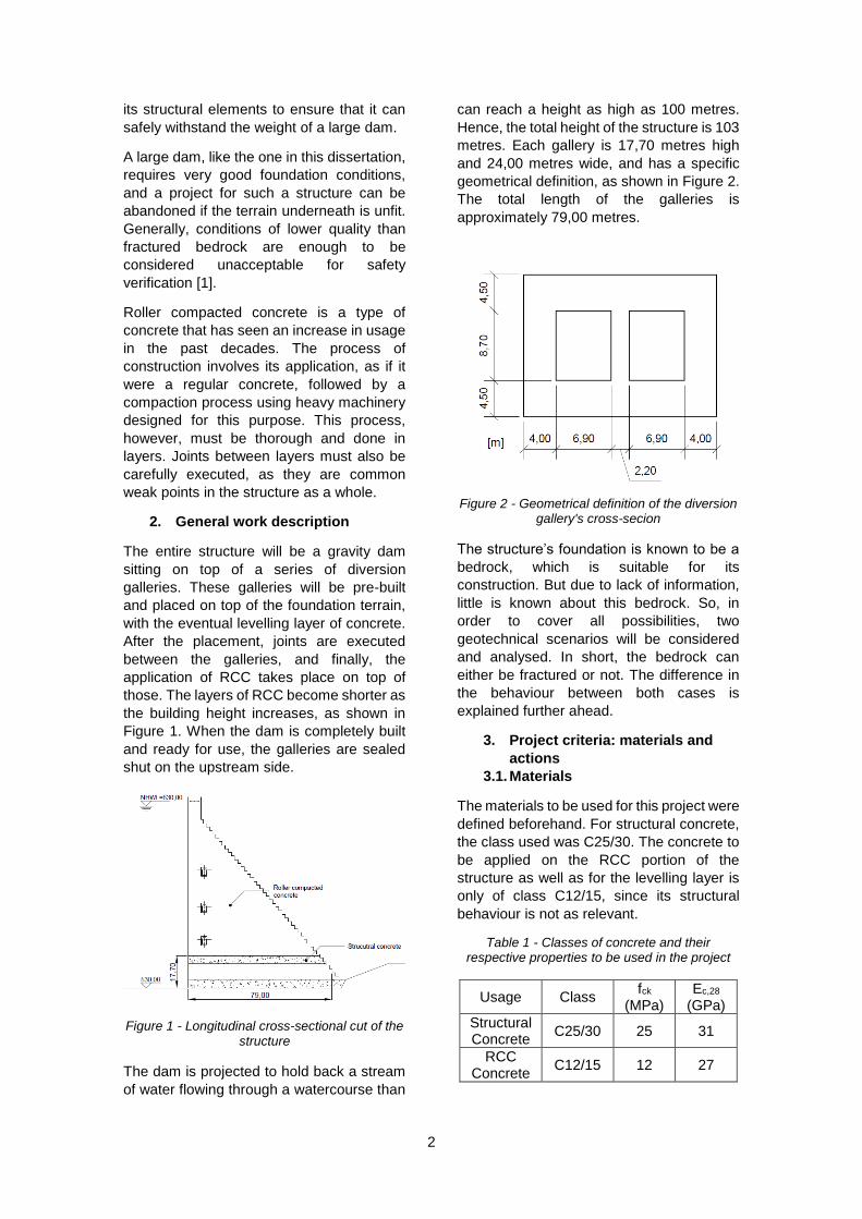
can reach a height as high as 100 metres.
Hence, the total height of the structure is 103
metres. Each gallery is 17,70 metres high
and 24,00 metres wide, and has a specific
geometrical definition, as shown in Figure 2.
The total length of the galleries is
approximately 79,00 metres.
Figure 2 - Geometrical definition of the diversion gallery's cross-secion
The structure’s foundation is known to be a
bedrock, which is suitable for its
construction. But due to lack of information,
little is known about this bedrock. So, in
order to cover all possibilities, two
geotechnical scenarios will be considered
and analysed. In short, the bedrock can
either be fractured or not. The difference in
the behaviour between both cases is
explained further ahead.
3. Project criteria: materials and
actions
3.1. Materials
The materials to be used for this project were
defined beforehand. For structural concrete,
the class used was C25/30. The concrete to
be applied on the RCC portion of the
structure as well as for the levelling layer is
only of class C12/15, since its structural
behaviour is not as relevant.
Table 1 - Classes of concrete and their respective properties to be used in the project
Usage Class fck
(MPa) Ec,28
(GPa)
Structural Concrete
C25/30 25 31
RCC Concrete
C12/15 12 27
3
For the steel rebar, the class to be used was
defined as A 500 NR.
Table 2 - Properties of the steel class used in the project
Steel Class fyk (MPa) Es (GPa)
A 500 NR 500 200
It is worth mentioning that, even though the
class C25/30 was defined initially for this
project, it does not comply with the terms
specified in E 464 2005 [3]. These norms
stipulate that a structure that is alternatively
wet and dry during its lifetime belongs in the
exposure class XC4, and therefore the
lowest concrete class allowed by these
terms is a C30/37. In spite of this, all
calculations and models produced of this
structure assumed that it consisted of a
C25/30 concrete. Should the project move
forward, all calculations and models are to
be redone using the values correspondent to
this new class.
In terms of concrete cover, it is important to
ensure that the corrosion of reinforcement
elements is to be avoided. As stated in the
paragraph above, an exposure class of XC4
is regarded to be of high importance for the
durability of a reinforced concrete structure.
According to [3], structures with an exposure
class of XC4 and a lifetime of 100 years,
have to ensure a concrete cover of 50
millimetres.
3.2. Actions
This structure will be designed mainly to
verify safety criteria for Ultimate Limit States
and Serviceability Limit States stipulated by
[4]. The only exceptions are for safety
regarding the shear force design, which will
comply to the rules stated in REBAP
(Regulamento de Estruturas de Betão
Armado e Pré-esforçado) [5] and for the
RCC dam design which will be executed as
stipulated in EM 1110-2-2200 [6].
Three load combinations were considered to
cover all possible worst case scenarios.
However, there is a bigger emphasis in the
constructive process of the dam. Table 3 and
Table 4 include all safety coefficients and all
partial coefficients, respectively.
Table 3 - Safety coefficients to be applied on the loads in ULS
ULS PP SP IL
Combination 1 1,35 - -
Combination 2 1,35 1,5 -
Combination 3 1,35 1,5 1,5
Table 4 - Partial coefficients to be applied on the loads in SLS
SLS PP SP IL
Combination 1 1 - -
Combination 2 1 1 -
Combination 3 1 1 1
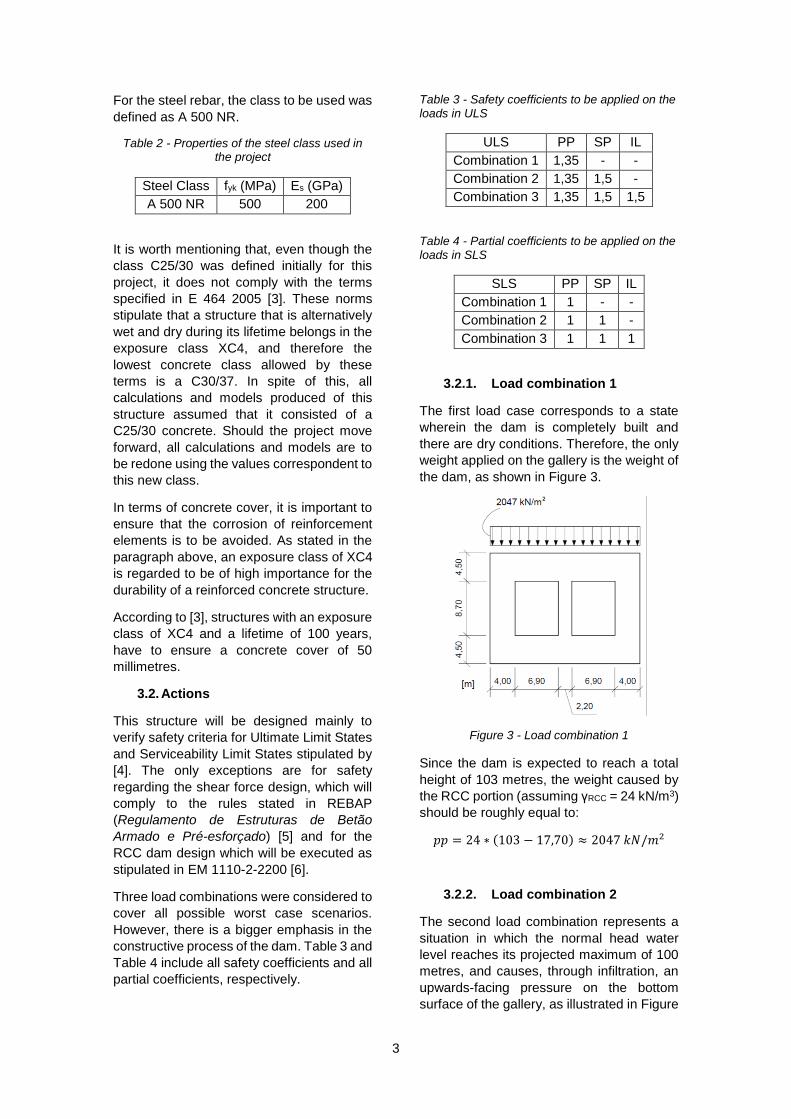
3.2.1. Load combination 1
The first load case corresponds to a state
wherein the dam is completely built and
there are dry conditions. Therefore, the only
weight applied on the gallery is the weight of
the dam, as shown in Figure 3.
Figure 3 - Load combination 1
Since the dam is expected to reach a total
height of 103 metres, the weight caused by
the RCC portion (assuming γRCC = 24 kN/m3)
should be roughly equal to:
𝑝𝑝 = 24 ∗ (103 − 17,70) ≈ 2047 𝑘𝑁/𝑚2
3.2.2. Load combination 2
The second load combination represents a
situation in which the normal head water
level reaches its projected maximum of 100
metres, and causes, through infiltration, an
upwards-facing pressure on the bottom
surface of the gallery, as illustrated in Figure

4
4. This pressure, if considered being applied
in a hydrostatic regime, is approximately:
𝑠𝑝 = 100 ∗ 9,8 = 980 𝑘𝑁/𝑚2
Besides this load, it also includes the one
caused by the weight of the dam, specified
in 3.2.1.
Figure 4 - Load combination 2
3.2.3. Load combination 3
The third load combination considers the
possibility of a rupture in the joints between
galleries, which can result in water infiltration
in the gaps formed. This infiltration will cause
lateral pressures on the sides of the
galleries. Like the previous load
combination, the scenario is worse when the
water’s level reaches its maximum of 100
metres. The lateral pressures on the gallery
will be approximately:
𝐼𝑙𝑡𝑜𝑝 = (100 − 17,70) ∗ 9,8 = 806,5 𝑘𝑁/𝑚2
𝐼𝑙𝑏𝑜𝑡𝑡𝑜𝑚 = 100 ∗ 9,8 = 980 𝑘𝑁/𝑚2
Besides the lateral pressures, the buoyancy
referred in 3.2.2 is also included, and so is
the weight of the dam. The loads are
represented in Figure 5.
Figure 5 - Load combination 3
4. Modelling of the structure and
safety verification
4.1. Model I
The first model to be used to calculate the
structure’s internal forces and moments
consists of a series of one-dimensional
elements. These create a structure on its
own where its elements coincide with the
axes of the elements of the real one, as
shown in Figure 6.
Figure 6 - Model of the gallery using one-dimensional elements
This model consists of using tabled values
for certain loads. These values can be
encountered in [7]. Since there is no load
case that includes an upwards-facing
pressure on the bottom surface, the only
option is to consider this pressure as a
“reduction” of the reaction caused by the
weight of the dam. Conservatively, and in a
safety point of view, it is not reasonable to
consider a reduction in the terrain surface’s
reaction, and therefore, load combinations 1
and 2 are considered equal.
The tabled values (shown in Table 5)
correspond solely to the moments on the
nodes of the structure (A to F). All the other
internal forces, including mid-span moments

5
must be obtained through equilibrium, and
are shown in Figure 7.
Table 5 - Moments obtained in the main nodes (values in kNm/m)
Section Combinations
1 and 2 Combination 3
A; E -5376.8 -20 653.5
B -35692.9 -27 919.3
C; F -5376.8 -20 833.8
D -35692.9 -28 099.6
Figure 7 – ULS Internal forces and bending moment diagrams for the first (and second) load
combination
Using these values, a complete structural
design can be made with respect to Ultimate
Limit States. However, this model is
expected to generate results that do not
adequately represent the reality. To have a
notion of the amount of steel rebar
necessary, the most influencing result would
require one layer of 32//0.100 plus three
more layers of 32//0.200 through sections
B and D, for flexural strength alone.
Another reason to disregard this model’s
verisimilitude is present in the fact that this
model did not take the elasticity of the
foundation into account. The models
described further ahead will take this into
account.
4.2. Model II
Similar to Model I, the second will also
consist of one-dimensional elements
composing the entire structure. This one,
however, will be executed using a finite
element method with a structural analysis
software program.
This model is expected to generate results
that will be slightly more realistic that the
previous one. The geometry is the same, but
in this case it is possible to simulate the
elastic support conditions.
4.2.1. Modelling the structure
It was referred that the foundation is
necessarily a bedrock, albeit not knowing its
condition. The most intuitive way to model
the support conditions is to assume that the
bottom parts of the gallery are in contact with
a Winkler spring bed as shown in Figure 8,
governed by the following equation:
𝑅(𝑥) = 𝑘𝑠 ∙ 𝑤(𝑥)
Where 𝑅(𝑥) is the reaction function for a
certain position on the bar (𝑥), 𝑘𝑠 is the
Winkler spring stiffness parameter, and 𝑤(𝑥)
is the displacement function for the position
𝑥.
The Winkler spring coefficient depends on
the type of foundation, and in general terms,
gets higher as the stiffness of the foundation
increases. Two values for the different
scenarios were defined and are present in
Table 6.

6
Table 6 - Case denomination and Winkler spring coefficients
Case F1 Case F2
Good geotechnical conditions
Reasonable geotechnical conditions
K = 7 500 000 kN/m3
K = 500 000 kN/m3
Figure 8 - Gallery Structure on a Winkler spring bed
Besides this, it is important to refer that since
the foundation is no longer being considered
rigid, there is now a difference between the
first two loading scenarios. Since this is a
foundation, the springs were modelled to
resist to compression only.
Considering alternations between load
cases and geotechnical scenarios, a total of
six different cases are to be studied for the
second model. They are summarized in
Table 7.
Table 7 - Denominations for case scenarios to be analysed with Model II
Load combination
Geotechnical scenario
Case
1 F1 1
1 F2 2
2 F1 3
2 F2 4
3 F1 5
3 F2 6
Since this model is to be run in a software, a
discretization must be made before the
simulation is run. One-dimensional elements
generally require low computational time, so
finite elements as short as 0,125 metres long
were adopted for the horizontal segments
and 0,165 metres long for the vertical ones.
4.2.2. Results
The model was run for all six cases and all
the internal force and moment (N, V, M)
diagrams were obtained. A diagram for the
spring bed reaction was obtained for every
case as well.
The first analysis of the results will focus on
the spring bed reaction, and a comparison
between geotechnical scenarios will be
made. To avoid an exhaustive presentation,
only the reaction diagrams for the first load
combination will be presented. They are
shown in Figure 9 and Figure 10, (scenario
F1 and F2, respectively).
Figure 9 - Reaction diagram for load case 1 (K = 7 500 000 kN/m3)
Figure 10 - Reaction diagram for load case 1 (K = 500 000 kN/m3)
By observing the reaction diagrams for each
geotechnical case, it can be concluded that
the diagram will have a bigger variability if
the Winkler spring coefficient is larger. This
means that the reaction gets closer to a
constant diagram, the smaller this coefficient
is. As a consequence, the shear force along
these elements will be closer to a first degree
function. It’s also relevant to mention that, in
the other load cases, the uplift due to the
presence of water happens. This results in
an overall smaller reaction, which generates
zones where the reaction even reaches
zero.
0
5000
10000
0 10 20
Rea
ctio
n (
kN/m
)
Distance (m)
0
5000
10000
0 10 20
Rea
ctio
n (
kN/m
)
Distance (m)
7
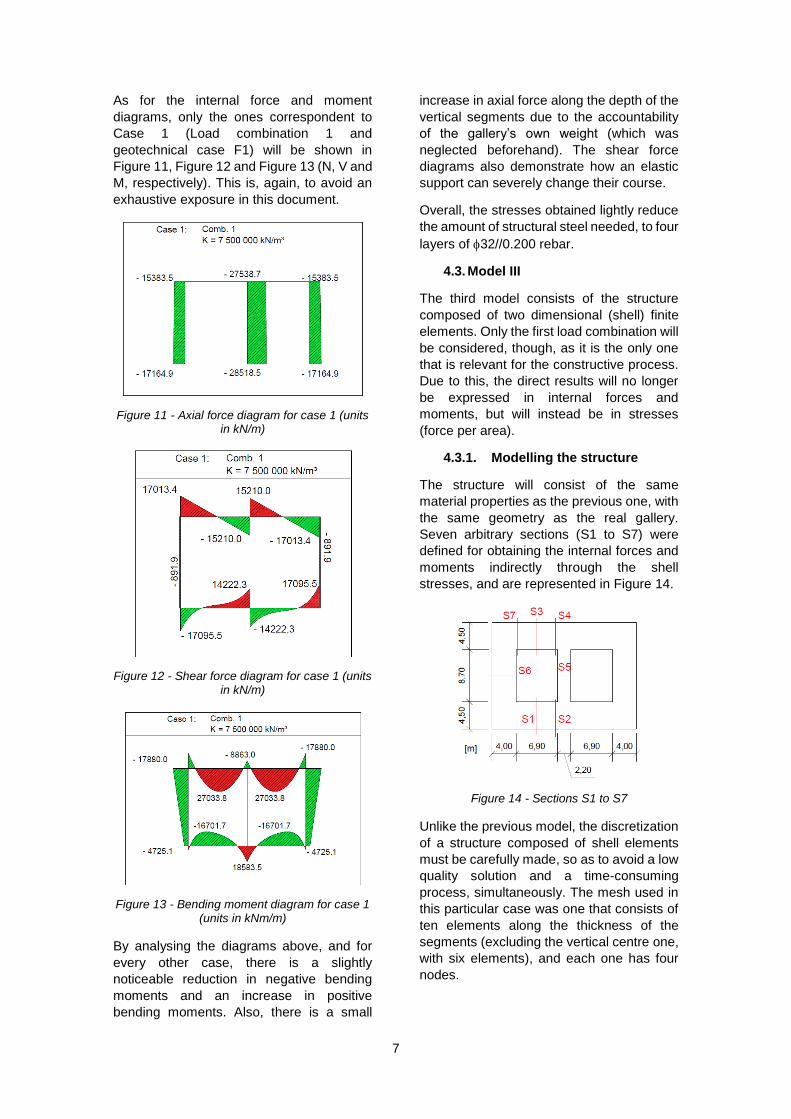
As for the internal force and moment
diagrams, only the ones correspondent to
Case 1 (Load combination 1 and
geotechnical case F1) will be shown in
Figure 11, Figure 12 and Figure 13 (N, V and
M, respectively). This is, again, to avoid an
exhaustive exposure in this document.
Figure 11 - Axial force diagram for case 1 (units in kN/m)
Figure 12 - Shear force diagram for case 1 (units in kN/m)
Figure 13 - Bending moment diagram for case 1 (units in kNm/m)
By analysing the diagrams above, and for
every other case, there is a slightly
noticeable reduction in negative bending
moments and an increase in positive
bending moments. Also, there is a small
increase in axial force along the depth of the
vertical segments due to the accountability
of the gallery’s own weight (which was
neglected beforehand). The shear force
diagrams also demonstrate how an elastic
support can severely change their course.
Overall, the stresses obtained lightly reduce
the amount of structural steel needed, to four
layers of 32//0.200 rebar.
4.3. Model III
The third model consists of the structure
composed of two dimensional (shell) finite
elements. Only the first load combination will
be considered, though, as it is the only one
that is relevant for the constructive process.
Due to this, the direct results will no longer
be expressed in internal forces and
moments, but will instead be in stresses
(force per area).
4.3.1. Modelling the structure
The structure will consist of the same
material properties as the previous one, with
the same geometry as the real gallery.
Seven arbitrary sections (S1 to S7) were
defined for obtaining the internal forces and
moments indirectly through the shell
stresses, and are represented in Figure 14.
Figure 14 - Sections S1 to S7
Unlike the previous model, the discretization
of a structure composed of shell elements
must be carefully made, so as to avoid a low
quality solution and a time-consuming
process, simultaneously. The mesh used in
this particular case was one that consists of
ten elements along the thickness of the
segments (excluding the vertical centre one,
with six elements), and each one has four
nodes.

8
4.3.2. Results
As mentioned earlier, the results for this
simulation will be in the format of shell
stresses. They are denominated as σ11
(horizontal axial stresses), σ22 (vertical axial
stresses) and σ12 (shear stresses). They are
represented in Figure 15, Figure 16 and
Figure 17, respectively.
Figure 15 - σ11 stresses (model III, units in kPa)
Figure 16 - σ22 stresses (model III, units in kPa)
Figure 17 - σ12 stresses (model III, units in kPa)
By observing the stresses, the following
conclusions can be made:
there is a significant mid-span
moment generated on the
horizontal segments (σ11)
there is a highly compressed area
on the vertical segments (σ22)
there are high concentrations of
shear stresses near the vertical
segments, suggesting higher
values of shear force (σ12)
4.4. Model IV
The final model is the most important one for
this dissertation, as it is the one that
represents a situation as close to reality as
possible. It consists of the same structure
modelled with the same elements, but it also
includes the constructive process for all the
(2-metre-high) RCC layers.
4.4.1. Modelling the structure
Since this model actually takes the RCC into
account as a material, and not just a load, it
needs to be modelled as such, so it is
necessary to know its physical properties.
According to [8], formula 4-2, the modulus of
elasticity (E, in psi) for the RCC, in the
absence of experimental data, is given by:
𝐸 = 57000(𝑓𝑐𝑘)1/2
Where fck is the characteristic compressive
strength of the concrete class used for the
RCC, and must be expressed in psi. Using
fck = 1740 psi (12 MPa), we get
E = 2 377 658,5 psi (16,40 GPa).
According to paragraph 4.3 b. of the same
document, the coefficient of Poisson for an
RCC ranges between 0,17 and 0,22. And in
the absence of empirical data, a value of
0,20 is recommended.
The mesh used in the model is identical to
the one in Model III. As for the RCC mesh,
its elements are as identical as possible to
the ones on the gallery, each also composed
of four nodes. The border between the
reinforced concrete (C25/30) and the RCC
has no incompatible nodes whatsoever.
4.4.2. Results
The final results obtained for this model will
be used to calculate internal forces and
moments and subsequently to design the

9
section for safety checking. The stresses
were calculated by the software and are
represented in Figure 18, Figure 19 and
Figure 20.
Figure 18 - σ11 stresses (model IV, K = 500 000 kN/m3, units in kPa)
Figure 19 – σ22 stresses (model IV, K = 500 000 kN/m3, units in kPa)
Figure 20 – σ12 stresses (model IV, K = 500 000 kN/m3, units in kPa)
When compared to the previous model, the
diagrams barely show any difference. The
values, however, differ slightly, especially in
the middle section between the two top
segments. This happens due to the
presence of the RCC on top of the gallery.
4.5. Safety check
Using only the values obtained for model IV,
it is possible to create an envelope for
internal forces and moments in order to
verify the safety in the design of the
structure. To obtain these internal forces and
moments, the stresses must be integrated
for every section (S1 to S7). For ultimate limit
states, the envelope is represented in Table
8.
Table 8 - Envelope for the ULS internal forces and moments for sections S1 to S7 (model IV)
Sec- tion
Internal forces and moments
Nsd (kN/m)
Vsd (kN/m)
Msd (kNm/m)
S1 -881,8 -1367,3 -15916,8
S2 268,4 7388,8 6180,6
S3 4423,0 -1448,2 8067,8
S4 4850,6 8412,2 -7322,2
S5 -19756,6 0,3 1952,5
S6 -19452,3 715,3 10220,4
S7 3175,1 6741,6 -2685,5
By observing the values in Table 8, in can be
confirmed that the disparity in results
between model IV and II is immense.
Besides ULS, the cracking check for SLS
must also be executed. To summarize, the
width of the crack in a service situation, wk,
must not be greater than the limit stipulated
by [4] (wk,lim), which is equal to 0,30
millimetres in this case. The results of the
structural design can be checked in Table 9
and Table 10.
Table 9 - Reinforcement bars used for all sections (S1 to S7)
Sections Top rebar Bottom rebar
S1;S2 3 layers
32//0.20
2 layers
32//0.20
S3;S7 3 layers
32//0.20
4 layers
32//0.20
S4 4 layers
32//0.20
4 layers
32//0.20
S5 32//0.20 32//0.20
S6 2 layers
32//0.20
2 layers
32//0.20

10
Table 10 - Resistant bending moments and crack widths after concrete design
Section Mrd
+
(kNm/m) Mrd
-
(kNm/m) wk
(mm)
S1 16377,4 -23485,2 0,28
S2 14008,8 -21174,8 0,20
S3 16202,2 -12584,5 0,23
S4 15309,8 -15309,6 0,25
S5 8583,2 -8583,2 0,00
S6 37743,9 -37743,9 0,00
S7 18798,0 -15187,9 0,20
As for shear design, the top sections will be
constructed with 32//0.20(//0.50) rebar and
the bottom sections with 32//0.20(//0.40).
The vertical segments will not require shear
reinforcement due to their high compression
forces regardless of the situation.
Regarding the RCC, two safety checking
criteria stated in [6] must be verified. For the
load case considered, there cannot be any
tension stresses in the structure and
compressive stresses must not exceed 30%
of the concrete class’s characteristic
compression strength (3,6 MPa).
The first criterion is roughly verified,
however, the second is not entirely due to
high vertical compression stresses on the
sides, just above the gallery, which go as
high as 4,7 MPa.
5. Conclusions
As a general rule, hydraulic structures are
massive, and must be carefully designed
knowing that the principles adopted in
regular structures may not be reasonable in
these cases. Besides this, it is also important
to compare the order of magnitude in both
stresses and the amount of steel
reinforcement bars between common
structures and hydraulic ones.
Regarding this case, one very important
conclusion must be drawn about the overall
design. Due to the high compressive
stresses in the sides of the RCC block, a
readjustment to the gallery’s thickness
would help reduce the stresses in the more
fragile region.
Finally, it is worth mentioning that a project
of this size and importance must include a
very thorough hydraulic design as well. It
should also include a check of the dam’s
global stability and a structural design of the
plugs that will close the gallery after the
construction of the dam. This, however is
falls out of the context of this dissertation.
6. References
[1] Design of Gravity Dams, Bureau of
Reclamation, 1976
[2] Ribeiro, A. Bettencourt (1999)
“Betão Compactado com Cilindros”,
LNEC
[3] “Concrete. Prescriptive
methodology for a design working
life of 50 and of 100 years under the
environmental exposure”, E 464
2005 (LNEC)
[4] Eurocode 2: “Design of concrete
structures – Part 1-1: General rules
and rules for buildings”, EN 1992-1-
1:2004
[5] “Regulamento de Estruturas de
Betão Armado e Pré-Esforçado”
[6] US Army Corps. Of Engineers 1995
– “Gravity Dam Design”
[7] Isnard,V., Grekow,A., Mrozowicz,P.,
Formulario del Ingeniero: Metodos
practicos de calculo de obras de
ingeniería, Urmo S.A. Ediciones;
[8] US Army Corps. Of Engineers 1995
– “Roller Compacted Concrete”