Embed Size (px)
Citation preview

1
Structural Design of a Tensioned Suspended Roof
Eduardo António Pires Costa
Civil Engineering Department, Instituto Superior Técnico, Universidade de Lisboa
June 2017
1. INTRODUCTION
Structures with cable elements have been playing an important role in Civil Engineering since a long
time. Since the Industrial Revolution it can be witnessed an evolution of the structures supported by
cables, culminating in the current times with the execution of bridges and roofs with increasing spans
and aesthetic emphasis, made possible by the use of pre-stressed cables, as the main element, in the
transmission of the acting loads.
The suspended roof of the Praça Cerimonial, adjacent to the Pavilhão de Portugal building, commonly
known as the Pala do Pavilhão de Portugal, is considered an icon of concrete structures in Portugal.
It was also considered by the British newspaper the guardian one of the ten best concrete structures in
the world, along with structures such as the Pantheon in Rome [1]. It is essentially a small thick concrete
membrane with a parabolic shaped surface, suspended by steel cables anchored in two parallel
structures made of reinforced concrete buttresses, joined in their crown by stress-distributing slabs [2].
This was the structure that inspired the theme of this dissertation.
The purpose of this dissertation is the design of a tensioned suspended roof element and its supporting
structure. The object of study of this roof will be the square of the Faculdade de Medicina Dentária in
Cidade Universitária in Lisbon. It is mainly a zone for pedestrians, which provides access to the
auditorium under the square, and can also be used for outdoor events. This roof is intended to conceive
a lightweight roof that transmits the idea of space amplitude, thus enhancing the aesthetic level of the
building.
2. DESIGN PRINCIPLES OF SUSPENDED ROOFS
Before beginning the process of designing the roof, it is necessary to answer a fundamental question:
what equation describes the equilibrium configuration of a cable suspended roof?

2
The way the loads acting on the cables are considered, influences their equilibrium position, and
consequently their final configuration when subjected to a particular load. Two load cases are analyzed,
one in which the cables are subjected to the action of a distributed load (case 1) and another in which
the cables are submitted only to their own weight (case 2) [3].
Figure 1 Case 1: Suspended cable submitted to a Figure 2 Case 2: Suspended cable submitted to its
distributed load. [3] own weight. [3]
In case 1 the equilibrium configuration of the suspended cable is described by a parabola given by
expression (1):
𝑦 =𝑝
2𝐻 𝑥2 −
𝑝𝑙
2𝐻𝑥 (1)
For case 2 the equilibrium configuration of the cable is given by a catenary equation according to
expression (2):
𝑦 =𝐻
𝑔[𝑐𝑜𝑠ℎ (
𝑔
𝐻𝑥 −
𝑔𝑙
2𝐻) − 𝑐𝑜𝑠ℎ (
𝑔𝑙
2𝐻)] (2)
In these expressions 𝐻 represents the horizontal component of the cable force, which is constant
throughout its entire length.
Taking into account that the roof to be designed is tensioned by cables in which the cables are
surrounded by a concrete slab, the weight of the structure is the conditioning load, whereby the
equilibrium configuration is described by a catenary. However, the catenary equation is not simple and
would imply a more cumbersome design when compared to the parabolic equation that defines the
equilibrium configuration of the first load case.
In order to understand the differences between the two equilibrium configurations, a suspended roof is
defined with 40 m of span and 4 m half-span deflection, in which the cables are surrounded by a 20 cm
thick concrete slab (LC30/33), dimensions close to the roof to be designed. The equations defining the
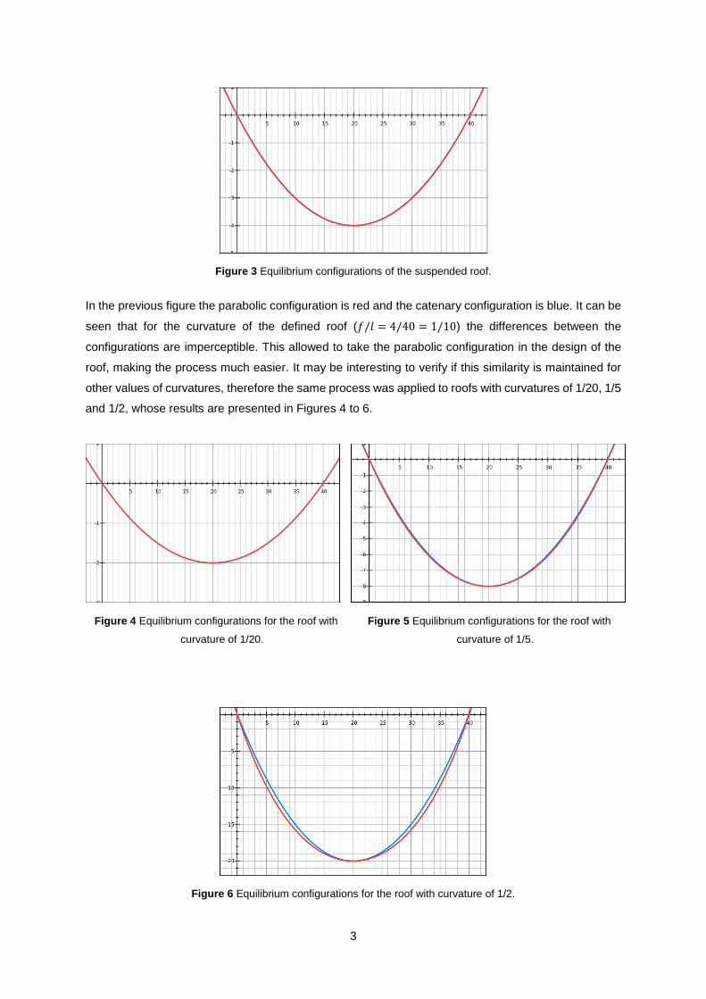
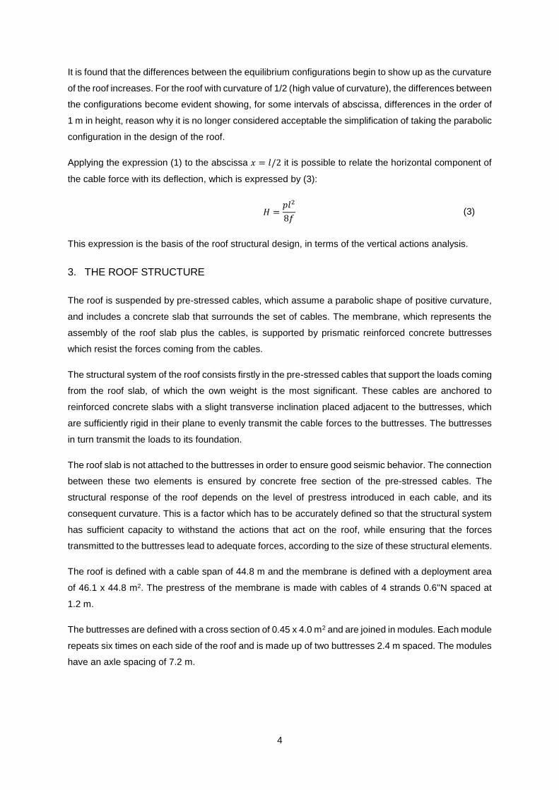
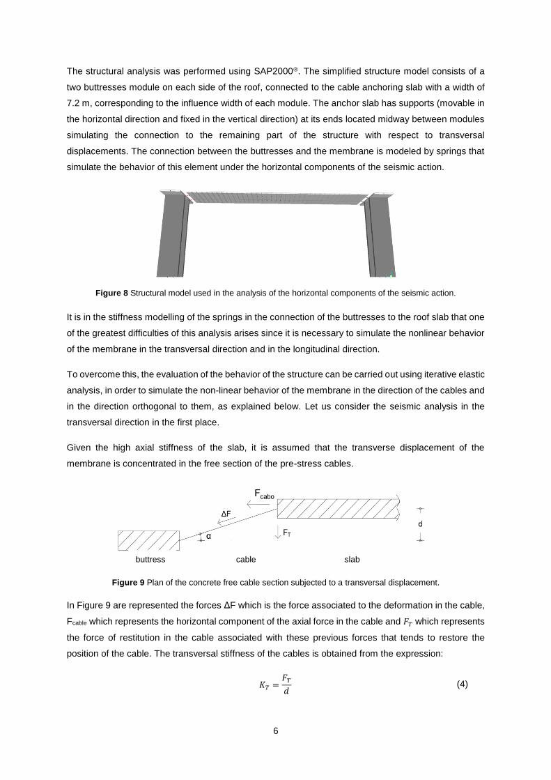
two configurations were applied and represented graphically in Figure 3.
3
Figure 3 Equilibrium configurations of the suspended roof.
In the previous figure the parabolic configuration is red and the catenary configuration is blue. It can be
seen that for the curvature of the defined roof (𝑓/𝑙 = 4/40 = 1/10) the differences between the
configurations are imperceptible. This allowed to take the parabolic configuration in the design of the
roof, making the process much easier. It may be interesting to verify if this similarity is maintained for
other values of curvatures, therefore the same process was applied to roofs with curvatures of 1/20, 1/5
and 1/2, whose results are presented in Figures 4 to 6.
Figure 4 Equilibrium configurations for the roof with Figure 5 Equilibrium configurations for the roof with
curvature of 1/20. curvature of 1/5.
Figure 6 Equilibrium configurations for the roof with curvature of 1/2.
4
It is found that the differences between the equilibrium configurations begin to show up as the curvature
of the roof increases. For the roof with curvature of 1/2 (high value of curvature), the differences between
the configurations become evident showing, for some intervals of abscissa, differences in the order of
1 m in height, reason why it is no longer considered acceptable the simplification of taking the parabolic
configuration in the design of the roof.
Applying the expression (1) to the abscissa 𝑥 = 𝑙/2 it is possible to relate the horizontal component of
the cable force with its deflection, which is expressed by (3):
𝐻 =𝑝𝑙2
8𝑓 (3)
This expression is the basis of the roof structural design, in terms of the vertical actions analysis.
3. THE ROOF STRUCTURE
The roof is suspended by pre-stressed cables, which assume a parabolic shape of positive curvature,
and includes a concrete slab that surrounds the set of cables. The membrane, which represents the
assembly of the roof slab plus the cables, is supported by prismatic reinforced concrete buttresses
which resist the forces coming from the cables.
The structural system of the roof consists firstly in the pre-stressed cables that support the loads coming
from the roof slab, of which the own weight is the most significant. These cables are anchored to
reinforced concrete slabs with a slight transverse inclination placed adjacent to the buttresses, which
are sufficiently rigid in their plane to evenly transmit the cable forces to the buttresses. The buttresses
in turn transmit the loads to its foundation.
The roof slab is not attached to the buttresses in order to ensure good seismic behavior. The connection
between these two elements is ensured by concrete free section of the pre-stressed cables. The
structural response of the roof depends on the level of prestress introduced in each cable, and its
consequent curvature. This is a factor which has to be accurately defined so that the structural system
has sufficient capacity to withstand the actions that act on the roof, while ensuring that the forces
transmitted to the buttresses lead to adequate forces, according to the size of these structural elements.
The roof is defined with a cable span of 44.8 m and the membrane is defined with a deployment area
of 46.1 x 44.8 m2. The prestress of the membrane is made with cables of 4 strands 0.6''N spaced at
1.2 m.
The buttresses are defined with a cross section of 0.45 x 4.0 m2 and are joined in modules. Each module
repeats six times on each side of the roof and is made up of two buttresses 2.4 m spaced. The modules
have an axle spacing of 7.2 m.

5
The height of the buttresses varies between 15.7 and 17.0 m, since their upper face has a slope equal
to the slope of the anchoring slab, which in turn is equal to the initial slope of the pre-stressed cables.
The roof slab is 20 cm thick and has a 3.5 m half-span deflection and the anchor slab is 30 cm thick.
The materials defined for the structural elements were: concrete C35/45 for the buttresses and slab of
anchorage and light concrete L30/33 for the roof slab. A500 NR SD steel was adopted for ordinary
reinforcement and Y1860 steel for prestress reinforcement.
The cross section of the roof structure and the architecture of its subjacent building is presented in
Figure 7.
Figure 7 Cross section of the roof structure and its subjacent building.
4. STRUCTURAL ANALYSIS AND MODELLING
The combinations of actions relevant to the design of the roof structure are: the combination of actions
for persistent or transient design situations in which gravitational loads, membrane prestressing and
wind are the actions to be taken into account, and the combination of actions for seismic project
situations, in which the seismic action joins the permanent loads.
For the first combination, the analysis of the structure response can be done using simple models.
Defining the vertical design load and using expression (3) it is possible to determine the cables forces
and with this value design the structural elements of the roof.
The evaluation of the structure’s behavior relative to the seismic action has some difficulty given the
non-linear behavior of the roof membrane in response to this action. It is recalled that the membrane is
not rigidly attached to the buttresses and that the connection between these two elements is carried out
by a concrete free section of pre-stressed cables. This solution is very advantageous for the seismic
behaviour of the roof.
6
The structural analysis was performed using SAP2000®. The simplified structure model consists of a
two buttresses module on each side of the roof, connected to the cable anchoring slab with a width of
7.2 m, corresponding to the influence width of each module. The anchor slab has supports (movable in
the horizontal direction and fixed in the vertical direction) at its ends located midway between modules
simulating the connection to the remaining part of the structure with respect to transversal
displacements. The connection between the buttresses and the membrane is modeled by springs that
simulate the behavior of this element under the horizontal components of the seismic action.
Figure 8 Structural model used in the analysis of the horizontal components of the seismic action.
It is in the stiffness modelling of the springs in the connection of the buttresses to the roof slab that one
of the greatest difficulties of this analysis arises since it is necessary to simulate the nonlinear behavior
of the membrane in the transversal direction and in the longitudinal direction.
To overcome this, the evaluation of the behavior of the structure can be carried out using iterative elastic
analysis, in order to simulate the non-linear behavior of the membrane in the direction of the cables and
in the direction orthogonal to them, as explained below. Let us consider the seismic analysis in the
transversal direction in the first place.
Given the high axial stiffness of the slab, it is assumed that the transverse displacement of the
membrane is concentrated in the free section of the pre-stress cables.
Figure 9 Plan of the concrete free cable section subjected to a transversal displacement.
In Figure 9 are represented the forces ΔF which is the force associated to the deformation in the cable,
Fcable which represents the horizontal component of the axial force in the cable and 𝐹𝑇 which represents
the force of restitution in the cable associated with these previous forces that tends to restore the
position of the cable. The transversal stiffness of the cables is obtained from the expression:
𝐾𝑇 =𝐹𝑇
𝑑 (4)
Fcable
buttress cable slab
7
0
30
60
90
120
150
180
210
0 0.04 0.08 0.12 0.16 0.2
Forc
e F
T[k
N]
Displacement d [m]
0
250
500
750
1000
1250
0 0.04 0.08 0.12 0.16 0.2
Stif
fne
ss K
T[k
N/m
]
Displacement d [m]
0
30
60
90
120
150
180
0 0.04 0.08 0.12 0.16 0.2
Forc
e F
T1[k
N]
Displacement d [m]
0
10
20
30
40
50
0 0.04 0.08 0.12 0.16 0.2
Forc
e F
T2[k
N]
Displacement d [m]
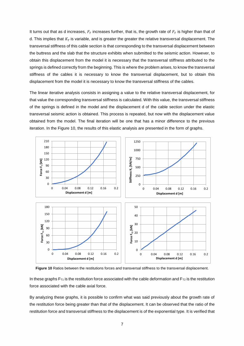
It turns out that as d increases, 𝐹𝑇 increases further, that is, the growth rate of 𝐹𝑇 is higher than that of
d. This implies that 𝐾𝑇 is variable, and is greater the greater the relative transversal displacement. The
transversal stiffness of this cable section is that corresponding to the transversal displacement between
the buttress and the slab that the structure exhibits when submitted to the seismic action. However, to
obtain this displacement from the model it is necessary that the transversal stiffness attributed to the
springs is defined correctly from the beginning. This is where the problem arises, to know the transversal
stiffness of the cables it is necessary to know the transversal displacement, but to obtain this
displacement from the model it is necessary to know the transversal stiffness of the cables.
The linear iterative analysis consists in assigning a value to the relative transversal displacement, for
that value the corresponding transversal stiffness is calculated. With this value, the transversal stiffness
of the springs is defined in the model and the displacement d of the cable section under the elastic
transversal seismic action is obtained. This process is repeated, but now with the displacement value
obtained from the model. The final iteration will be one that has a minor difference to the previous
iteration. In the Figure 10, the results of this elastic analysis are presented in the form of graphs.
Figure 10 Ratios between the restitutions forces and transversal stiffness to the transversal displacement.
In these graphs FT1 is the restitution force associated with the cable deformation and FT2 is the restitution
force associated with the cable axial force.
By analyzing these graphs, it is possible to confirm what was said previously about the growth rate of
the restitution force being greater than that of the displacement. It can be observed that the ratio of the
restitution force and transversal stiffness to the displacement is of the exponential type. It is verified that
8
this exponential character comes from the relation between the restitution force associated with the
deformation (FT1) and the transversal displacement.
With respect to the restitution force associated to the cable axial force (FT2), its ratio with the transversal
displacement is linear, which means that the associated transversal stiffness is constant, which explains
the transversal stiffness that the cable presents when the transversal displacement is zero. If the
stiffness associated with this force is calculated for the displacement of 0.04 m,
𝐾𝑇 = 11/0.04 = 275 𝑘𝑁/𝑚 is obtained, which corresponds to the transversal stiffness of the cable
when the transversal displacement is zero.
However, in this analysis it was not considered an important aspect of the roof behavior that is
associated with the effect of membrane deflection variation. A transversal displacement of the roof slab
also leads to a relative displacement between the latter and the buttresses in the longitudinal direction.
This relative displacement would only translate into a variation of axial deformation of the membrane if
it were flat. However, the membrane is not a planar element, having a deflection which is associated
with the balance of the vertical load acting on the roof.
A longitudinal relative displacement between the ends of the roof slab will essentially cause a variation
of the deflection, it being shown, that the axial deformation of the membrane is negligible compared to
the previous effect. The variation of the deflection will be translated, essentially, in the variation of the
axial force in the membrane that will balance the vertical loads of the roof for the new curvature of the
membrane.
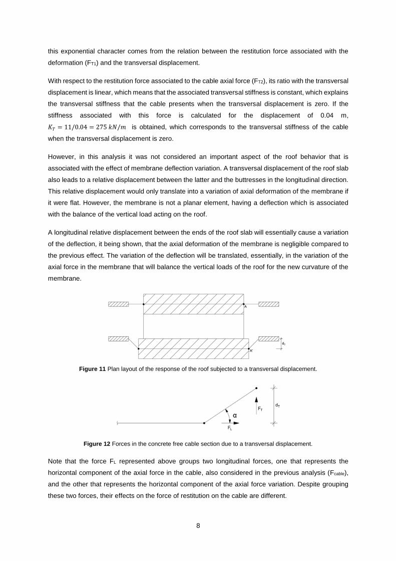
Figure 11 Plan layout of the response of the roof subjected to a transversal displacement.
Figure 12 Forces in the concrete free cable section due to a transversal displacement.
Note that the force FL represented above groups two longitudinal forces, one that represents the
horizontal component of the axial force in the cable, also considered in the previous analysis (Fcable),
and the other that represents the horizontal component of the axial force variation. Despite grouping
these two forces, their effects on the force of restitution on the cable are different.
9
0
30
60
90
120
150
180
0 0.1 0.2 0.3 0.4
∆P
[kN
]
dH [m]
0
50
100
150
200
250
300
350
400
0 0.1 0.2 0.3 0.4
KL
[kN
/m]
dH [m]
The iterative elastic analysis and the results obtained considering the deflection variaton effect are
similar to the first analysis performed, being that a lower transversal stiffness is obtained for this effect.
Since these stiffnesses work in series, it is the lower stiffness that conditions the behavior of the roof in
the orthogonal direction to the pre-stress cables. Therefore, the transversal stiffness of the springs is
defined with the value of the second analysis.
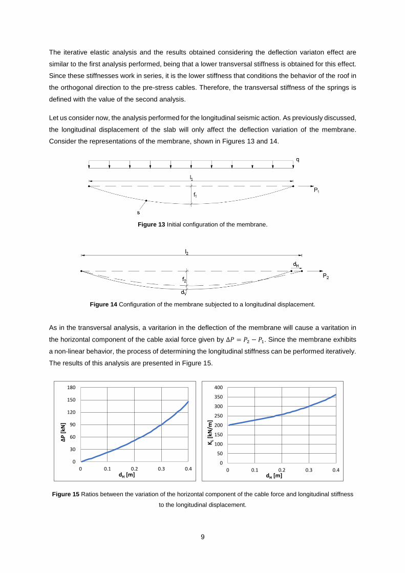
Let us consider now, the analysis performed for the longitudinal seismic action. As previously discussed,
the longitudinal displacement of the slab will only affect the deflection variation of the membrane.
Consider the representations of the membrane, shown in Figures 13 and 14.
Figure 13 Initial configuration of the membrane.
Figure 14 Configuration of the membrane subjected to a longitudinal displacement.
As in the transversal analysis, a varitarion in the deflection of the membrane will cause a varitation in
the horizontal component of the cable axial force given by ∆𝑃 = 𝑃2 − 𝑃1. Since the membrane exhibits
a non-linear behavior, the process of determining the longitudinal stiffness can be performed iteratively.
The results of this analysis are presented in Figure 15.
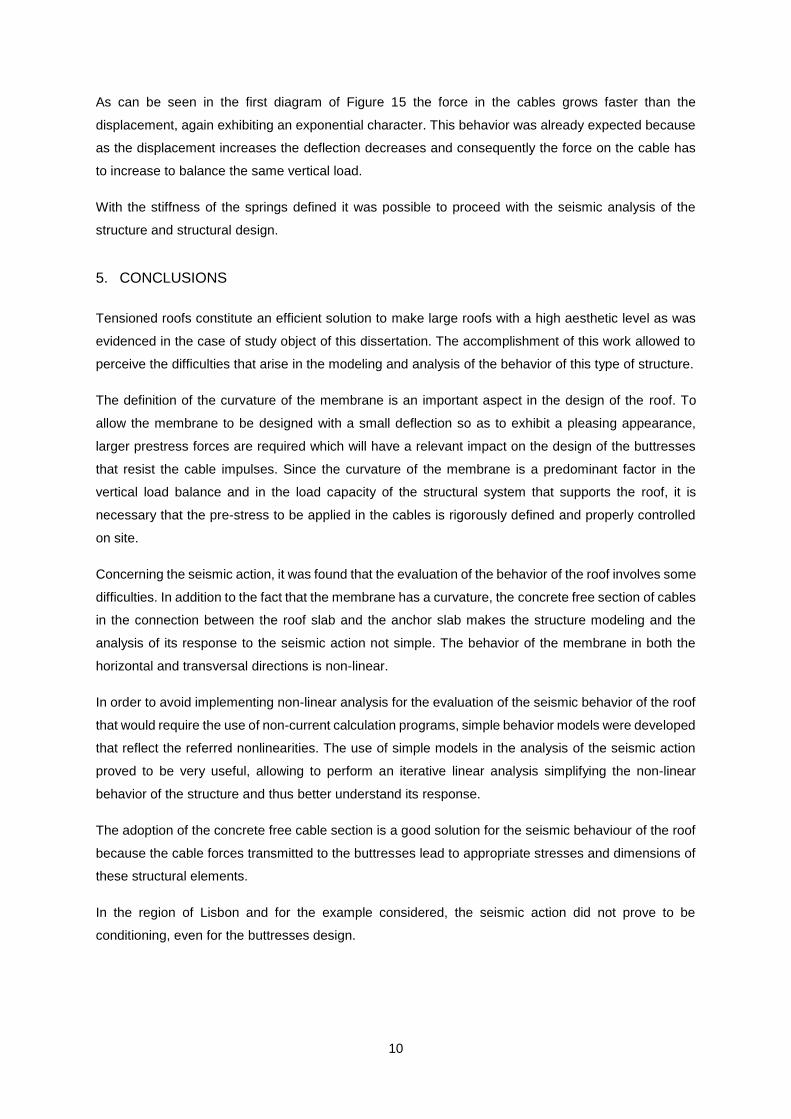
Figure 15 Ratios between the variation of the horizontal component of the cable force and longitudinal stiffness
to the longitudinal displacement.
10
As can be seen in the first diagram of Figure 15 the force in the cables grows faster than the
displacement, again exhibiting an exponential character. This behavior was already expected because
as the displacement increases the deflection decreases and consequently the force on the cable has
to increase to balance the same vertical load.
With the stiffness of the springs defined it was possible to proceed with the seismic analysis of the
structure and structural design.
5. CONCLUSIONS
Tensioned roofs constitute an efficient solution to make large roofs with a high aesthetic level as was
evidenced in the case of study object of this dissertation. The accomplishment of this work allowed to
perceive the difficulties that arise in the modeling and analysis of the behavior of this type of structure.
The definition of the curvature of the membrane is an important aspect in the design of the roof. To
allow the membrane to be designed with a small deflection so as to exhibit a pleasing appearance,
larger prestress forces are required which will have a relevant impact on the design of the buttresses
that resist the cable impulses. Since the curvature of the membrane is a predominant factor in the
vertical load balance and in the load capacity of the structural system that supports the roof, it is
necessary that the pre-stress to be applied in the cables is rigorously defined and properly controlled
on site.
Concerning the seismic action, it was found that the evaluation of the behavior of the roof involves some
difficulties. In addition to the fact that the membrane has a curvature, the concrete free section of cables
in the connection between the roof slab and the anchor slab makes the structure modeling and the
analysis of its response to the seismic action not simple. The behavior of the membrane in both the
horizontal and transversal directions is non-linear.
In order to avoid implementing non-linear analysis for the evaluation of the seismic behavior of the roof
that would require the use of non-current calculation programs, simple behavior models were developed
that reflect the referred nonlinearities. The use of simple models in the analysis of the seismic action
proved to be very useful, allowing to perform an iterative linear analysis simplifying the non-linear
behavior of the structure and thus better understand its response.
The adoption of the concrete free cable section is a good solution for the seismic behaviour of the roof
because the cable forces transmitted to the buttresses lead to appropriate stresses and dimensions of
these structural elements.
In the region of Lisbon and for the example considered, the seismic action did not prove to be
conditioning, even for the buttresses design.

11
6. REFERENCES
[1] Moore, R., The 10 best concrete buildings, https://www.theguardian.com/artanddesign/2016/jan/
08/10-best-concrete-buildings-architecture-pantheon-gaudi-corbusier, consultado em Setembro de
2016;
[2] Segadães Tavares, A., A “Pala” e o Pavilhão de Portugal na EXPO’98 e a utilização de betão leve
estrutural, Prémio Leca de Construção 98, 1999;
[3] Pereira Júnior, E.J., Uma formulação consistente para análise não linear de estruturas de cabos
suspensos, Universidade Federal de Minas Gerais, 2002.