Embed Size (px)
Citation preview

National!Institute of!Aerospace!
Structural Boron Nitride Nanotube Composite Development
February 21, 2014
Catharine Fay
NASA Langley Research Center Advanced Materials and Processing Branch
Strategic Partner:

• Vehicle weight is a primary driver for most NASA missions. Reducing vehicle weight can: – Expand mission capability – Reduce launch costs – Reduce fuel consumption – Systems analysis shows that
reducing materials mass by 20% leads to a 30% reduction in launch vehicle gross weight
– Same study indicates a 50% reduction in materials mass reduces launch vehicle gross weight by >60%, enables potential single stage to orbit designs
– Additional multifunctionality: thermal, radiation protection, sensing capabilities, no corrosion
2
Effect of Materials Mass Reduction on Launch Vehicle Gross Weight
Project Goal
Strategic Overview
Potential Impact: Produce advanced BNNT composites with higher thermal stability, lightweight, no corrosion, tough, and radiation shielding effectiveness

BNNT
0
200
400
600
800
1000
0 20 40 60 80 100 120 140 160 180
Spec
ific
Mod
ulus
, GPa
/(g/c
m3 )
Specific Strength, GPA/(g/cm3)
IM7
M46J
M46J CFRP Al 2219
SiC/Be
TiFoamSand BeAl
Al2O3/Al TiAl IM7 CFRP AlFoam
Nt/P
Nt/Al
0
50
100
150
200
250
300
0 0.5 1 1.5 2 2.5 3 3.5 Spec
ific
Mod
ulus
, GPa
/(g/
cm3 )
Specific Strength, GPA/(g/cm3)
Baseline Materials 5-10 years (TRL = 4-6) 10-20 years + (TRL = 1-3)
Charlie E. Harris, M. J. Shuart, H. Gray, NASA/TM-2002-211664
The structural material properties
for nanotubes significantly
exceed those of current SOA
materials.
Properties of Materials for Vehicle Structure
@ RT SWCNT
BNNT
0
200
400
600
800
1000
0 20 40 60 80 100 120 140 160 180
Spec
ific
Mod
ulus
, GPa
/(g/c
m3 )
Specific Strength, GPA/(g/cm3)
Baseline Materials 5-10 years (TRL = 4-6) 10-20 years + (TRL = 1-3)
Charlie E. Harris, M. J. Shuart, H. Gray, NASA/TM-2002-211664
SiC/Be
TiAl
0
50
100
150
200
250
300
0 0.5 1 1.5 2 2.5 3 3.5 Spec
ific
Mod
ulus
, GPa
/(g/
cm3 )
Specific Strength, GPA/(g/cm3)
@ 700⁰C
Properties of Materials for Vehicle Structure

Technology Areas TA 6 7, 10 and 12
High Temperature Components
Micrometeoroid Protection
Structure: Stronger/Tougher/Lighter
Components
Ultralightweight Wire Insulation
Life Support Membranes
(e.g. water, CO2)
Lightweight Tethers
Radiation Shielding/ Protection
5
Thermal Protection Systems

6 National Institute of Aerospace
4 Aerothermodynamics Branch, LaRC Research Directorate
2 Advanced Sensing and Optical Measurements Branch, LaRC Research Directorate
Radia&on Sheila Thibeault1
Team
1 Advanced Materials and Processing Branch, LaRC Research Directorate
Modeling Peter Gnoffo4
Diagnos&cs Paul Danehy2
Characteriza&on & Processing Cheol Park6
Systems Analysis Kevin Earle5
5 Space Mission and Analysis Branch, LaRC Systems Analysis & Concept Directorate
Synthesis & Produc&on Joseph Lee2
BNNT Team
Technical Group Lead Catharine Fay1
Hoa Luong3 Godfrey SauJ6
Jennifer Inman2 Stephen Jones2
Derek Liechty4 Vesselin Yamakov6
Glen King1 Sharon Lowther1 Sang-‐Hyon Chu6 Luke Gibbons6 Jin Ho Kang6 Amanda Tiano6 Samantha Applin6 Wanda Gresham3
Hyunjung Kim6
3 Materials Experiments Branch, LaRC Research Directorate
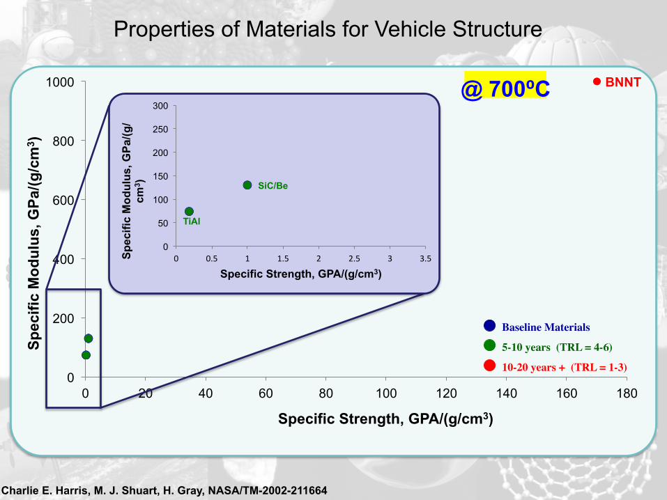
NASA BNNT Product Strategy Steps
BN Nanotubes Production Synthesis
7
• Two trained operators. • Runs on average 3 days a week 4 hours per day. (not including startup and shutdown/harvesting) • To date has produced approximately 9 grams of material. • Production rate between 15 and 20 mg per hour. • Enables purification and dispersion studies. • Enables fabrication of yarns mats and other structural components. • Enables Material Transfer Agreements to NIA and Universities.

BNNT Purification Progress
Acid Treatment Purification
Using nitric acid, remove boron
nanoparticles (an impurity) from sample.
• Boron nanoparticles removed
• Noticeable damage to the nanotubes resulting in poor quality of the acid-treated sample
• Acid-treated structural mats have no integrity
Thermal Purification
Use heat to remove boron nanoparticles
and potentially remove boron oxides (i.e.
water soluble impurities).
• Boron nanoparticle removal alternative
• Assumption: the darker the BNNT, the higher the boron content/impurity content; visible color change from a darker to a lighter-colored material
• Further analysis and investigation in progress
Surfactant Purification
Using surfactants, remove all impurities, which includes boron
nanoparticles and amorphous and crystalline BN.
• Least harmful method to purifying the nanotubes
• Potential removal of crystalline BN (which cannot be removed via other listed purification methods)
• Further analysis and investigation in progress; will include sonication and centrifugation as well*

Dispersion studies
• By surveying a variety of solvents/co-solvents, surfactants, and polymers (A), a solubility region for BNNTs was established (B) using Hansen solubility theory.
• Extending this knowledge, we generated BNNT structural composites (C) with a plethora of interesting properties (D).
DMF DMF/ Toluene
Toluene Acetone
CTAB Triton X-100
PVP SDBS

Frozen dispersion fabrication method
12% BNNT PU 30% BNNT PU 30% BNNT PU (drop)
50% BNNT PVA
50% BNNT PVA +
sonication
50% BNNT CP2
Before hot-press
20% BNNT PMMA
75% BNNT PVA
1 inch
After hot-press
67% BNNT-PU Pressed 67% BNNT-PU
1 inch New fabrication method simplifies processing for high
weight nanocomposites
This approach can be used to fabricate BNNT + polymers/epoxies and lock in the dispersion conditions
The “frozen dispersion” step is intermediate - the sample is
consolidated during hot-pressing
10% BNNT PVA
67 % BNNT PAN
PU - Polyurethane PMMA - Poly(methyl methacrylate) PVA - Polyvinyl alcohol PAN - Polyacrylonitrile CP2 – LaRC CP2 Polyimide

BNNT Purification, Dispersion, & Spinning
11
TEM images
BNNTs
Non-nanotube BN
BNNT in Chlorosulfonic (CSF) Acid (Superacid): Spontaneous dispersion and debundling
Continuous fiber spinning technology for armchair quantum wire
Matteo Pasquali Departments of Chemical & Biomolecular Engineering and Chemistry,
The Smalley Institute for Nanoscale Science & Technology The Ken Kennedy Institute for Information Technology
Rice University, Houston, TX; [email protected]
AFOSR Low Density Material Program Review Wright Brothers Institute, Dayton (OH), 4 June 2012
FIBER SPINNING
Collaboration with Teijin, manufacturers of Twaron (PPTA) and Toho Tenax (C fibers)
CNT superacid spinning CNT spun fibers
CNT spinning • BNNT Superacid Spinning in collaboration with Rice University
Rice University (Prof Matteo Pasquali) Stretched 35% aligned MWNT Stretched 25% aligned MWNT
SEM images of Stretched Aligned MWNT Sheets
SEM images of Stretched Aligned MWNT Sheets
Stretched 53% aligned MWNT
• BNNT Mat/Sheet Formation (filtering) Stretching BNNT Sheet à Composite Tape à Mechanical Tests
Stretching
CNT Sheet Aligned Sheet
Florida State University (Wang/Liang) FSU FSU
Liquid crystalline state
Need purified BNNT for spinning

Three Goals for BNNT Modeling • Define the environment in which tubes now grow.
– “Laser Vaporization and Plume Chemistry in a Boron Nitride Nanotube Production Rig”, JTHT, Vol. 27, No. 3, 2013
– Simulate domain for irradiated droplet suspended in space to better model convection currents – key to understanding nucleation site environment
• Define the optimum environment for growing BNNTs. – Observations suggest significant formation of tubes at nucleation sites rising
from heated surface, even before condensation wire is encountered – If tip growth mechanism: need to simulate nucleation of supersaturated BN
from rising plume on nucleation site(s) – If root growth mechanism: need to simulate micro-droplets of liquid Boron
ejected from heated surface • Melts at ~ 2600 K, Boils at ~ 5000 K at 200 psi • Simulate evolution of absorbed N2, N, and BN in micro-droplet as it rises in plume and
cools – Plan to explore molecular dynamics approach of Violi et al. (A multi-scale
computational approach for nanoparticle growth in combustion environments) • Explore modifications to rig by simulation to promote optimum
environment. – Directed jets may be used to speed or slow the plume dynamics, possibly
inducing recirculation through the hot zone rich in BN, to promote BNNT growth.

T, K
480046004400420040003800360034003200300028002600
Temperature ExceedingBoron Melting Point
Temperature Contours Around 1 mm Radius Boron Droplet
Can jets be used to: (1) Promote recirculation of micro-droplets through hot
(red) zone rich in N and BN? (2) Extend the length (or time of residence) in green
zone to extend life of molten micro-droplet before solidification
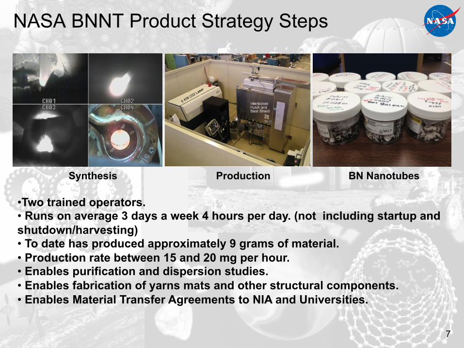
Optical Diagnostic Techniques for BNNT
• Need a detailed understand of chemistry and flow physics of nanotube generation and how the process changes under different operating conditions – Improve and validate simulation/modeling – Optimize material properties, production rate
• Specific Goals: – Determine gas and melt-ball temperatures – Determine amount of B2, B, BN, N and N2
• In-situ, on-surface measurement: – optical pyrometry for surface temperature
• Off-surface, gas phase measurement: – High-speed, high-resolution imaging
• Shadowgraph and visible emission – Species sensitive imaging (BN PLIF) – Temperature measurements (CARS)

Partnerships & Collaborations
• NASA LaRC Center (5 branches) – Glenn Research Center – Goddard Space Flight Center – Johnson Space Center – Ames Research Center
• Other Government – Air Force Office of Scientific
Research – NIST
• Commercial – BNNT, LLC – Momentive
• Universities – UC-Berkeley – Rice University – SUNY-Binghamton – VA Commonwealth University – University of North Texas – University of New Hampshire – NC State – Hampton University
• International – ONERA (France) – Institutode Nanociencia de
Aragon (Universidad de Zaragoza, Spain)
15
National!Institute of!Aerospace!
Strategic Partner

16
Hydrogen Storage BNNT
Hydrogenated BNNT
The fabrication processes of BN-BN composite precursor and different BN-BN composite structures (fiber, plate composite).
BNNT enables…………………
Multi-Functional All BN-BN Composite
B
CN
C fiber resource
Fig 3. TEM, EELS, and Raman spectra of BCNNT.
BCN Nanotubes
Fig 2. TEM image of
C60-BNNT (endo-doped) UC Berkeley
BxCyNz Nanotube (BCNNT) Development
Radiation Shielding Materials Containing Hydrogen, Boron, and Nitrogen: Systematic Computational and Experimental Study
BNNT BNNT