Embed Size (px)
Citation preview
542-1
Structural Behaviour of Sandwich Panels Constructed of Foam Cores and Flax FRP Facings
Betts, Dillon1, Sadeghian, Pedram1,3, and Fam, Amir2 1 Department of Civil and Resource Engineering, Dalhousie University, Canada 2 Department of Civil Engineering, Queen’s University, Canada 3 [email protected]
Abstract: In this study, the flexural behaviour of sandwich panels constructed of flax fibre-reinforced polymer (FRP) facings and closed cell polyisocyanurate foam cores was examined. A total of nine sandwich beam specimens (1200 mm long and 150 mm wide) made of 75 mm thick foam were prepared and tested under three-point bending. The parameters of the study were core density and facing thickness. Three different foam densities (32, 64, and 96 kg/m3) were used as well as three different facing thicknesses: one, two and three layers of a bidirectional flax fabric (400 g/m2). A bio-based epoxy resin was used to make FRPs. Several different failure mechanisms were observed during the testing, including: delamination, shear, crushing of the top face, tensile rupture of bottom face, and several combinations of these failures. It was observed that the shear and delamination failures occurred mainly in the low-density foam specimens, delamination and crushing of the compression face occurred mainly in the medium-density foam specimens, and that tensile rupture of the bottom face occurred in the high-density foam core specimens. As the tensile rupture of the bottom face occurred, it was concluded that the flax FRP facings reached full capacity in these cases and the foam did not cause premature failure.
1 INTRODUCTION
Sandwich panels are widely used building materials that are often used in applications where light weight is a requirement. They have high flexural strength as a lightweight core material separates the strong faces to provide a large moment of inertia to resist bending (Allen 1969). As fibre-reinforced polymers (FRPs) have relatively high specific strengths, they are a popular choice for facing materials. However, due to the relatively low strength of typical core materials, in large-scale structural applications the core strength often governs the failure mechanism and the FRP facings rarely reach their full tensile strength capacity. Therefore, the high strength of the FRP facings is often not required. This presents an opportunity to use a weaker, but more environmentally friendly material in place of the synthetic FRPs. Flax FRPs (FFRPs) are a sustainable option with which to replace synthetic FRPs as they have a lower embodied energy then traditional fibres such as a glass or carbon (Mak and Fam 2016). Typically, natural FRPs are weaker than typical glass and carbon FRPs, however as the core material often governs the capacity of sandwich panels, the reduction in strength is acceptable for this application (Sadeghian et al. 2016 and Fam et al. 2016).
In this study, sandwich panels with FFRP facings and foam cores were tested and analysed. This paper aims to provide insight into the failure mechanisms of sandwich panels with FFRP facings and to provide a simple analytical method with which to predict the general behaviour of these panels.
542-2
2 EXPERIMENTAL STUDY
2.1 Test Matrix
Nine sandwich panel specimens were fabricated and tested under three-point bending. The specimens were comprised of flax FRP facings and closed cell polyisocyanurate foam cores with a thickness of 75 mm. The test parameters were facing thickness and foam core density. Three facing thicknesses were compared (1, 2, and 3 layers of flax fabric) and three core densities (32, 64, and 96 kg/m3). The test matrix is shown in Table 1.
Table 1: Test matrix.
No. Specimen
I.D. Number of Layers
Core Density (kg/m3)
1 1FL-P200 1 32 2 2FL-P200 2 32 3 3FL-P200 3 32 4 1FL-P400 1 64 5 2FL-P400 2 64 6 3FL-P400 3 64 7 1FL-P600 1 96 8 2FL-P600 2 96 9 3FL-P600 3 96
2.2 Material Properties
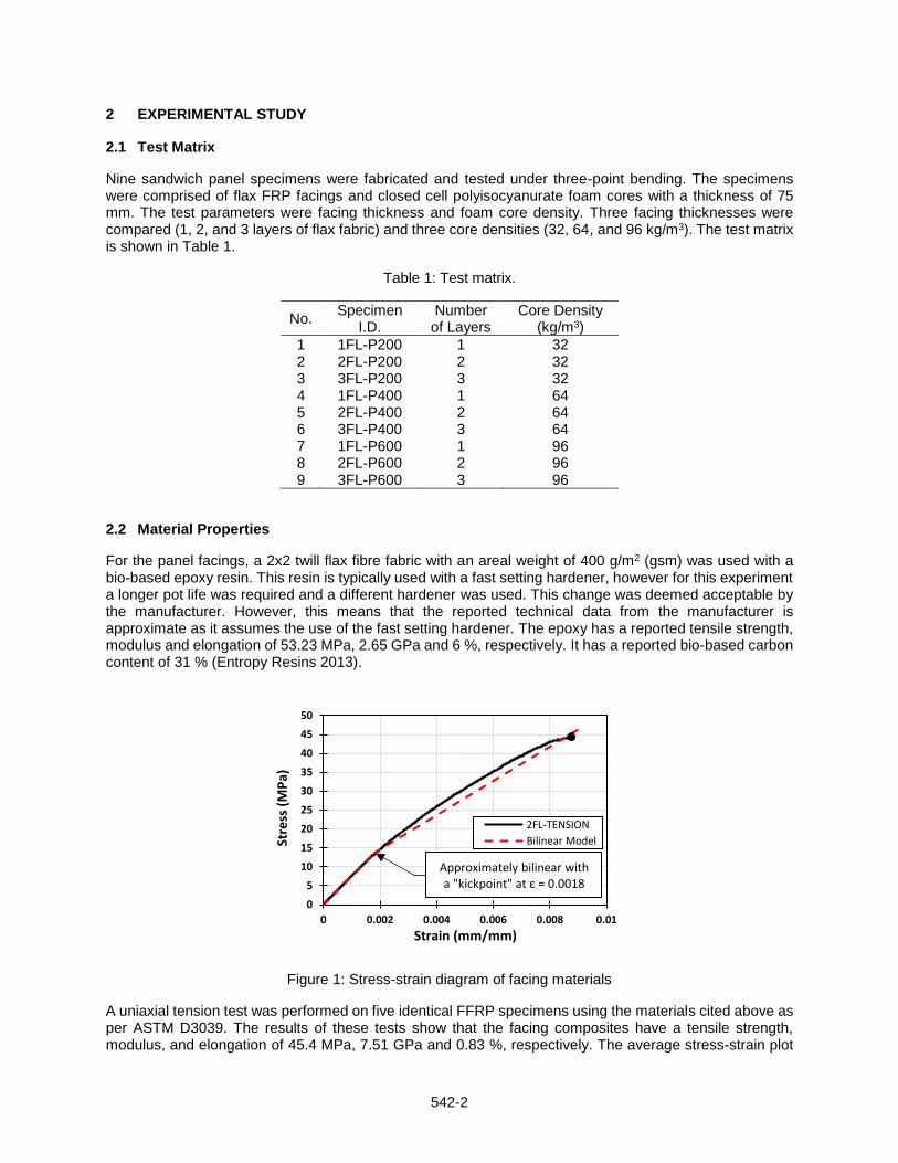
For the panel facings, a 2x2 twill flax fibre fabric with an areal weight of 400 g/m2 (gsm) was used with a bio-based epoxy resin. This resin is typically used with a fast setting hardener, however for this experiment a longer pot life was required and a different hardener was used. This change was deemed acceptable by the manufacturer. However, this means that the reported technical data from the manufacturer is approximate as it assumes the use of the fast setting hardener. The epoxy has a reported tensile strength, modulus and elongation of 53.23 MPa, 2.65 GPa and 6 %, respectively. It has a reported bio-based carbon content of 31 % (Entropy Resins 2013).
Figure 1: Stress-strain diagram of facing materials
A uniaxial tension test was performed on five identical FFRP specimens using the materials cited above as per ASTM D3039. The results of these tests show that the facing composites have a tensile strength, modulus, and elongation of 45.4 MPa, 7.51 GPa and 0.83 %, respectively. The average stress-strain plot
0
5
10
15
20
25
30
35
40
45
50
0 0.002 0.004 0.006 0.008 0.01
Stre
ss (
MP
a)
Strain (mm/mm)
2FL-TENSION
Bilinear Model
Approximately bilinear with a "kickpoint" at ε = 0.0018
542-3
of the tests is shown in Figure 1 as is a simple bilinear model of the curve. This bilinear model has a “kickpoint” at a strain of 0.0018 mm/mm.
Each specimen had a closed cell polyisocyanurate foam core. Three different densities were used: P200 (32 kg/m3), P400 (64 kg/m3) and P600 (96 kg/m3). Each foam type was purchased as 1200 mm wide by 2400 mm long by 75 mm thick. The moduli and strengths of each foam as given by the manufacturer are shown in Table 2 (ELFOAM 2016).
Table 2: Mechanical properties of foam cores.
Foam Type
Parallel to Rise Perpendicular to Rise
Ec Et G fcu ftu τu Ec Et G fcu ftu τu
P200 4 823 8 268 2 067 186 248 172 2 302 3 190 1 515 124 179 124
P400 14 469 18 603 5 856 585 551 379 9 646 10 748 5 167 427 406 344
P600 32 865 27 146 7 234 978 930 585 21 290 15 709 6 063 834 792 489
Note 1. Data is presented in kPa Note 2. Ec = Compressive Modulus, Et = Tensile Modulus, G = Shear Modulus, fcu = Compressive Strength, ftu =
Tensile Strength, τu = Shear Strength
2.3 Specimen Preparation
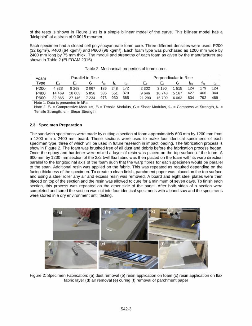
The sandwich specimens were made by cutting a section of foam approximately 600 mm by 1200 mm from a 1200 mm x 2400 mm board. These sections were used to make four identical specimens of each specimen type, three of which will be used in future research in impact loading. The fabrication process is show in Figure 2. The foam was brushed free of all dust and debris before the fabrication process began. Once the epoxy and hardener were mixed a layer of resin was placed on the top surface of the foam. A 600 mm by 1200 mm section of the 2x2 twill flax fabric was then placed on the foam with its warp direction parallel to the longitudinal axis of the foam such that the warp fibres for each specimen would be parallel to the span. Additional resin was applied on the fabric. This was repeated as required depending on the facing thickness of the specimen. To create a clean finish, parchment paper was placed on the top surface and using a steel roller any air and excess resin was removed. A board and eight steel plates were then placed on top of the section and the resin was allowed to cure for a minimum of seven days. To finish each section, this process was repeated on the other side of the panel. After both sides of a section were completed and cured the section was cut into four identical specimens with a band saw and the specimens were stored in a dry environment until testing.
Figure 2: Specimen Fabrication: (a) dust removal (b) resin application on foam (c) resin application on flax fabric layer (d) air removal (e) curing (f) removal of parchment paper
(d)
(b) (a) (c)
(e) (f)
542-4
2.4 Test Set-up and Instrumentation
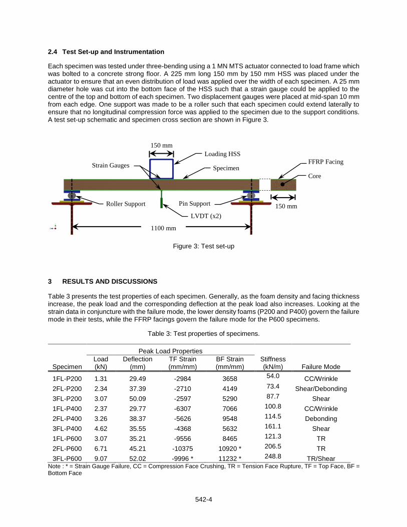
Each specimen was tested under three-bending using a 1 MN MTS actuator connected to load frame which was bolted to a concrete strong floor. A 225 mm long 150 mm by 150 mm HSS was placed under the actuator to ensure that an even distribution of load was applied over the width of each specimen. A 25 mm diameter hole was cut into the bottom face of the HSS such that a strain gauge could be applied to the centre of the top and bottom of each specimen. Two displacement gauges were placed at mid-span 10 mm from each edge. One support was made to be a roller such that each specimen could extend laterally to ensure that no longitudinal compression force was applied to the specimen due to the support conditions. A test set-up schematic and specimen cross section are shown in Figure 3.
Figure 3: Test set-up
3 RESULTS AND DISCUSSIONS
Table 3 presents the test properties of each specimen. Generally, as the foam density and facing thickness increase, the peak load and the corresponding deflection at the peak load also increases. Looking at the strain data in conjuncture with the failure mode, the lower density foams (P200 and P400) govern the failure mode in their tests, while the FFRP facings govern the failure mode for the P600 specimens.
Table 3: Test properties of specimens.
Peak Load Properties
Specimen Load (kN)
Deflection (mm)
TF Strain (mm/mm)
BF Strain (mm/mm)
Stiffness (kN/m) Failure Mode
1FL-P200 1.31 29.49 -2984 3658 54.0 CC/Wrinkle
2FL-P200 2.34 37.39 -2710 4149 73.4 Shear/Debonding
3FL-P200 3.07 50.09 -2597 5290 87.7 Shear
1FL-P400 2.37 29.77 -6307 7066 100.8 CC/Wrinkle
2FL-P400 3.26 38.37 -5626 9548 114.5 Debonding
3FL-P400 4.62 35.55 -4368 5632 161.1 Shear
1FL-P600 3.07 35.21 -9556 8465 121.3 TR
2FL-P600 6.71 45.21 -10375 10920 * 206.5 TR
3FL-P600 9.07 52.02 -9996 * 11232 * 248.8 TR/Shear Note : * = Strain Gauge Failure, CC = Compression Face Crushing, TR = Tension Face Rupture, TF = Top Face, BF = Bottom Face
Loading HSS
Specimen
Pin Support Roller Support
LVDT (x2)
1100 mm
mm
150 mm
Strain Gauges FFRP Facing
Core
150 mm
542-5
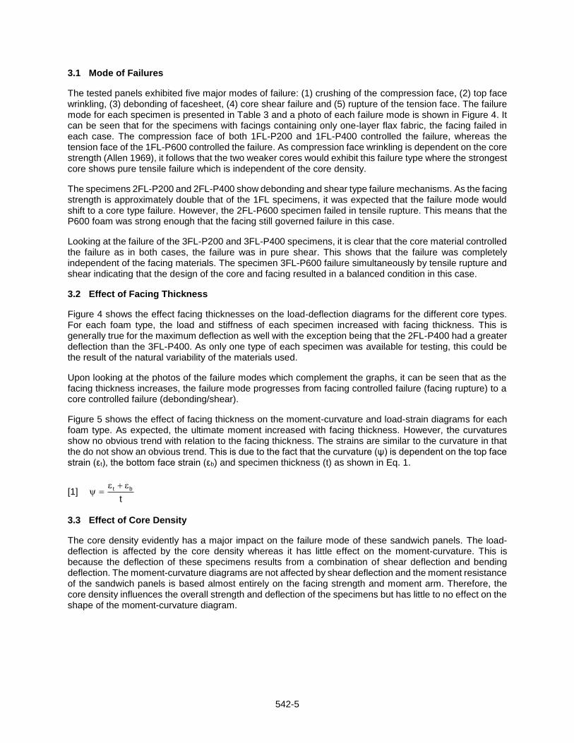
3.1 Mode of Failures
The tested panels exhibited five major modes of failure: (1) crushing of the compression face, (2) top face wrinkling, (3) debonding of facesheet, (4) core shear failure and (5) rupture of the tension face. The failure mode for each specimen is presented in Table 3 and a photo of each failure mode is shown in Figure 4. It can be seen that for the specimens with facings containing only one-layer flax fabric, the facing failed in each case. The compression face of both 1FL-P200 and 1FL-P400 controlled the failure, whereas the tension face of the 1FL-P600 controlled the failure. As compression face wrinkling is dependent on the core strength (Allen 1969), it follows that the two weaker cores would exhibit this failure type where the strongest core shows pure tensile failure which is independent of the core density.
The specimens 2FL-P200 and 2FL-P400 show debonding and shear type failure mechanisms. As the facing strength is approximately double that of the 1FL specimens, it was expected that the failure mode would shift to a core type failure. However, the 2FL-P600 specimen failed in tensile rupture. This means that the P600 foam was strong enough that the facing still governed failure in this case.
Looking at the failure of the 3FL-P200 and 3FL-P400 specimens, it is clear that the core material controlled the failure as in both cases, the failure was in pure shear. This shows that the failure was completely independent of the facing materials. The specimen 3FL-P600 failure simultaneously by tensile rupture and shear indicating that the design of the core and facing resulted in a balanced condition in this case.
3.2 Effect of Facing Thickness
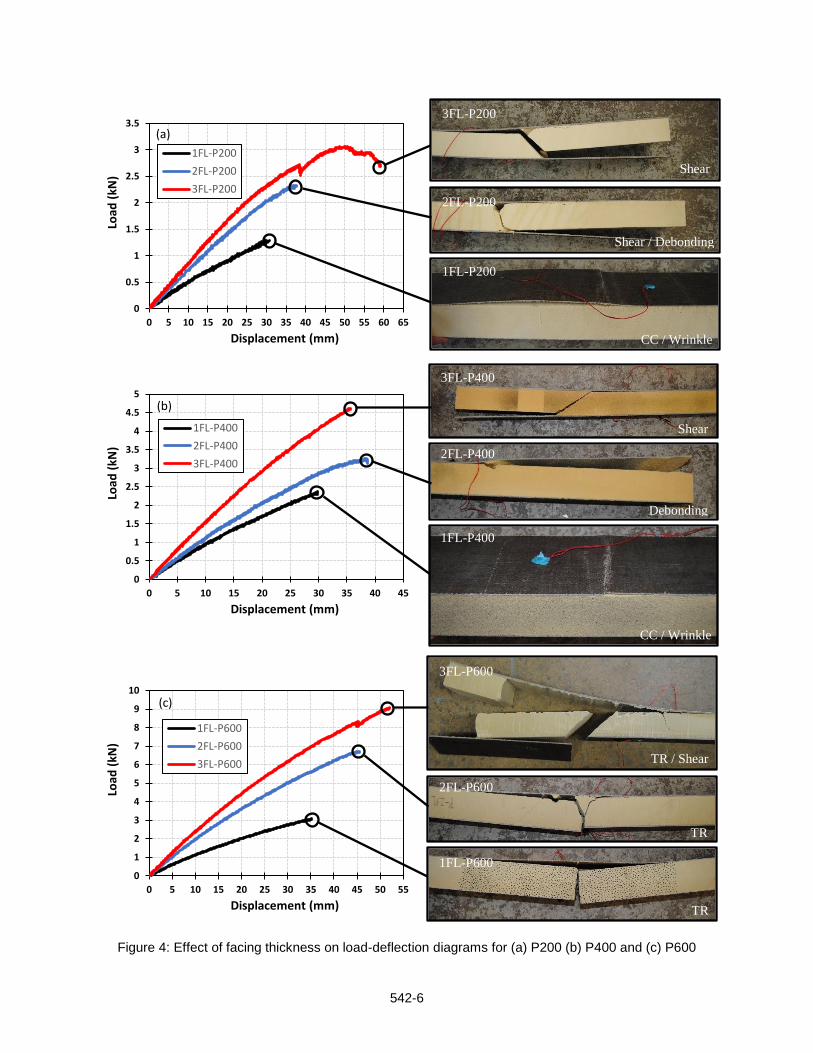
Figure 4 shows the effect facing thicknesses on the load-deflection diagrams for the different core types. For each foam type, the load and stiffness of each specimen increased with facing thickness. This is generally true for the maximum deflection as well with the exception being that the 2FL-P400 had a greater deflection than the 3FL-P400. As only one type of each specimen was available for testing, this could be the result of the natural variability of the materials used.
Upon looking at the photos of the failure modes which complement the graphs, it can be seen that as the facing thickness increases, the failure mode progresses from facing controlled failure (facing rupture) to a core controlled failure (debonding/shear).
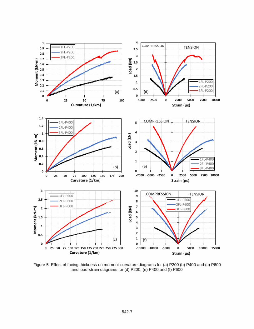
Figure 5 shows the effect of facing thickness on the moment-curvature and load-strain diagrams for each foam type. As expected, the ultimate moment increased with facing thickness. However, the curvatures show no obvious trend with relation to the facing thickness. The strains are similar to the curvature in that the do not show an obvious trend. This is due to the fact that the curvature (ψ) is dependent on the top face strain (εt), the bottom face strain (εb) and specimen thickness (t) as shown in Eq. 1.
[1] t
bt
3.3 Effect of Core Density
The core density evidently has a major impact on the failure mode of these sandwich panels. The load-deflection is affected by the core density whereas it has little effect on the moment-curvature. This is because the deflection of these specimens results from a combination of shear deflection and bending deflection. The moment-curvature diagrams are not affected by shear deflection and the moment resistance of the sandwich panels is based almost entirely on the facing strength and moment arm. Therefore, the core density influences the overall strength and deflection of the specimens but has little to no effect on the shape of the moment-curvature diagram.
542-6
Figure 4: Effect of facing thickness on load-deflection diagrams for (a) P200 (b) P400 and (c) P600
0
0.5
1
1.5
2
2.5
3
3.5
4
4.5
5
0 5 10 15 20 25 30 35 40 45
Load
(kN
)
Displacement (mm)
1FL-P400
2FL-P400
3FL-P400
(b)
0
1
2
3
4
5
6
7
8
9
10
0 5 10 15 20 25 30 35 40 45 50 55
Load
(kN
)
Displacement (mm)
1FL-P600
2FL-P600
3FL-P600
(c)
1FL-P200
2FL-P200
3FL-P200
1FL-P400
2FL-P400
3FL-P400
1FL-P600
2FL-P600
3FL-P600
0
0.5
1
1.5
2
2.5
3
3.5
0 5 10 15 20 25 30 35 40 45 50 55 60 65
Load
(kN
)
Displacement (mm)
1FL-P200
2FL-P200
3FL-P200
(a)
CC / Wrinkle
Shear / Debonding
Shear
Shear
Debonding
CC / Wrinkle
TR / Shear
TR
TR
542-7
Figure 5: Effect of facing thickness on moment-curvature diagrams for (a) P200 (b) P400 and (c) P600 and load-strain diagrams for (d) P200, (e) P400 and (f) P600
0
0.1
0.2
0.3
0.4
0.5
0.6
0.7
0.8
0.9
1
0 25 50 75 100
Mo
me
nt
(kN
-m)
Curvature (1/km)
1FL-P200
2FL-P200
3FL-P200
(a)
0
0.2
0.4
0.6
0.8
1
1.2
1.4
0 25 50 75 100 125 150 175 200
Mo
me
nt
(kN
-m)
Curvature (1/km)
1FL-P400
2FL-P400
3FL-P400
(b)
0
0.5
1
1.5
2
2.5
3
0 25 50 75 100 125 150 175 200 225 250 275 300
Mo
me
nt
(kN
-m)
Curvature (1/km)
1FL-P600
2FL-P600
3FL-P600
(c)
0
0.5
1
1.5
2
2.5
3
3.5
4
-5000 -2500 0 2500 5000 7500 10000
Load
(kN
)
Strain (με)
1FL-P2002FL-P2003FL-P200
COMPRESSION TENSION
(d)
0
1
2
3
4
5
-7500 -5000 -2500 0 2500 5000 7500 10000
Load
(kN
)
Strain (με)
1FL-P4002FL-P4003FL-P400
COMPRESSION TENSION
(e)
0
1
2
3
4
5
6
7
8
9
10
-15000 -10000 -5000 0 5000 10000 15000
Load
(kN
)
Strain (με)
1FL-P6002FL-P6003FL-P600
COMPRESSION TENSION
(f)
542-8
4 ANALYTICAL STUDY
4.1 Description of Model
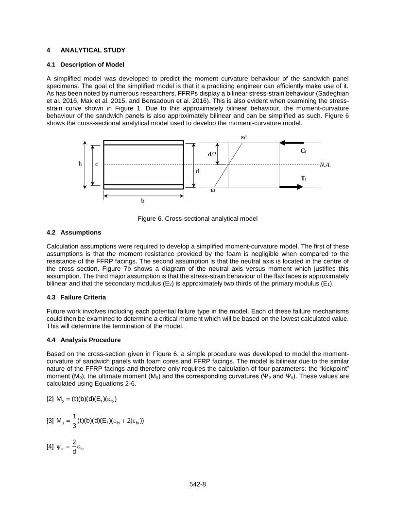
A simplified model was developed to predict the moment curvature behaviour of the sandwich panel specimens. The goal of the simplified model is that it a practicing engineer can efficiently make use of it. As has been noted by numerous researchers, FFRPs display a bilinear stress-strain behaviour (Sadeghian et al. 2016, Mak et al. 2015, and Bensadoun et al. 2016). This is also evident when examining the stress-strain curve shown in Figure 1. Due to this approximately bilinear behaviour, the moment-curvature behaviour of the sandwich panels is also approximately bilinear and can be simplified as such. Figure 6 shows the cross-sectional analytical model used to develop the moment-curvature model.
Figure 6. Cross-sectional analytical model
4.2 Assumptions
Calculation assumptions were required to develop a simplified moment-curvature model. The first of these assumptions is that the moment resistance provided by the foam is negligible when compared to the resistance of the FFRP facings. The second assumption is that the neutral axis is located in the centre of the cross section. Figure 7b shows a diagram of the neutral axis versus moment which justifies this assumption. The third major assumption is that the stress-strain behaviour of the flax faces is approximately bilinear and that the secondary modulus (E2) is approximately two thirds of the primary modulus (E1).
4.3 Failure Criteria
Future work involves including each potential failure type in the model. Each of these failure mechanisms could then be examined to determine a critical moment which will be based on the lowest calculated value. This will determine the termination of the model.
4.4 Analysis Procedure
Based on the cross-section given in Figure 6, a simple procedure was developed to model the moment-curvature of sandwich panels with foam cores and FFRP facings. The model is bilinear due to the similar nature of the FFRP facings and therefore only requires the calculation of four parameters: the “kickpoint” moment (Mo), the ultimate moment (Mu) and the corresponding curvatures (Ψo and Ψu). These values are calculated using Equations 2-6.
[2] ))(E)(d)(b)(t(M fofo
[3] ))(2)(E)(d)(b)(t(3
1M fufofu
[4] food
2
Cf
Tf
d/2
d c h
εf’
εf
N.A.
b

542-9
[5] fuud
2
[6]
f
fofufofu
E3
2
ff
Where εfo is the change in moduli of the flax fabric and ffo is the corresponding stress. εfu is the ultimate strain of the facing corresponding to the ultimate stress in the facing (f fu) which will be dependent on the critical failure criteria once it has been incorporated into the model.
4.5 Verification
Figure 7a shows the verification of the moment-curvature model for each of the P600 specimens and Figure 7b shows the neutral axis of 2FL-P600 versus the moment. The model was also verified with the test data of specimen FE5-V from the study by Mak et al. (2015). This verification is shown in Figure 7c. Using the load-strain data from the paper, shown in Figure 7d, the moment-curvature plot for specimen FE5-V was developed and subsequently compared with the simple moment-curvature model presented in this paper. As the model does not yet incorporate the failure mechanisms of the panels, an ultimate strain was chosen to match the experimental results.
As shown in Figure 7, the model is relatively accurate in predicting the moment-curvature behaviour of these sandwich panels. The slight inaccuracy of the model is to be expected as it is a simplified model. However, considering the ease of calculation, this model could be useful for practicing engineers in predicting the structural behaviour of these sustainable sandwich panels.
Figure 7. Verification of moment-curvature model
542-10
5 CONCLUSIONS
After testing the specimens under three-point bending, the results show that FFRP facing can be used make a balanced sandwich panel design with polyisocyanurate foams. This is shown by the fact that the sandwich panels with the P600 foam cores were able to achieve tensile face rupture before the failure of the core. The results show that the facing thickness has a major effect on the failure mechanism of these panels: as the facing thickness increases, it is more likely that the failure mode will be a type of core failure. The foam type did not show to have a significant effect on the moment-curvature of the specimens, but did influence the load-deflection diagrams. After the data analysis, a simple bilinear moment-curvature analysis procedure was developed to model the behaviour of FFRP-foam sandwich panels in bending. Future work in this research involves the completion of this model which will include: (i) including failure mechanisms to determine model termination and; (ii) developing load-deflection model considering both bending and shear deformations.
6 REFERENCES
Allen, HG. 1969. Analysis and Structural Design of Sandwich Panels, Pergamon Press, Oxford, UK. ASTM D3039. 2014. Standard Test Method for Tensile Properties of Polymer Matrix Composite Materials,
ASTM, International, West Conshohocken, PA, USA. Bensadoun, F., Vallons, K. A. M., Lessard, L. B., Verpoest, I., and Van Vuure, A. W. 2016. Fatigue
Behaviour Assessment of Flax–Epoxy Composites. Composites Part A: Applied Science and Manufacturing, 82: 253-266.
ELFOAM. 2016. ELFOAM P200: Polyisocyanurate Foam, Elliott Company, Indianapolis, IN, USA. ELFOAM. 2016. ELFOAM P400: Polyisocyanurate Foam, Elliott Company, Indianapolis, IN, USA.
ELFOAM. 2016. ELFOAM P600: Polyisocyanurate Foam, Elliott Company, Indianapolis, IN, USA. Entropy Resins. 2013. Super SAP ONE Epoxy Resin, Entropy Resins, Hayward, CA, USA. Fam, A., Sharaf, T., and Sadeghian, P. 2016. Fiber Element Model of Sandwich Panels with Soft Cores
and Composite Skins in Bending Considering Large Shear Deformations and Localized Skin Wrinkling. Journal of Engineering Mechanics, 142(5): 04016015:1-14.
Mak, K. and Fam, A. 2016. Bio Resins and Bio Fibers for FRP Applications in Structural Engineering
Applications. 7th International Conference on Advanced Composite Materials in Bridges and Structures, Canadian Society for Civil Engineering, Vancouver, BC, Canada, 6 p. paper.
Mak, K., Fam, A. and MacDougall C. 2015. Flexural Behavior of Sandwich Panels with Bio-FRP Skins Made
of Flax Fibers and Epoxidized Pine-oil Resin. Journal of Composites for Construction, 19(6): 04015005:1-13.
Sadeghian, P., Hristozov, D. and Wroblewski, L. 2016. Experimental and Analytical Behavior of Sandwich
Composite Beams: Comparison of Natural and Synthetic Materials. Journal of Sandwich Structures and Materials, 0(00): 1-21.