Embed Size (px)
Citation preview

Structural Appraisal Old Kent Water Reservoir, St Thomas’s Hill, Canterbury Client: Mr A. Bereza
T: 020 7253 2893 F:020 7253 2809 E: [email protected] W: www.form-sd.com
Form Structural Design Ltd, 31a Great Sutton Street, Clerkenwell, London, EC1V 0NA Registered office: Form Structural Design Ltd, Onega House, Sidcup, Kent DA14 6NE Company No.4504240
Form
Structural Design

Structural Appraisal Old Kent Water Reservoir, St Thomas’s Hill, Canterbury Client: Mr A. Bereza
CONTENTS 1.0 Contents 2.0 Introduction
2.1 Brief 2.2 Scope of appraisal 2.3 Limitations of appraisal 2.4 Date of appointment 2.5 Date site visited 2.6 Purpose of report 2.7 General description / Construction of the property 2.8 Archive information used
3.0 Findings
3.1 General 3.2 Exterior 3.3 Base slab 3.4 Walls 3.5 Roof 3.6 Roof support structure
4.0 Conclusion 5.0 Recommendations 6.0 Appendix A – Photographs 7.0 Appendix B – Measurement Survey Drawings 8.0 Appendix C – Historical Kent Water Information Page 1 of 25 Form Structural Design

Structural Appraisal Old Kent Water Reservoir, St Thomas’s Hill, Canterbury Client: Mr A. Bereza 2.0 Introduction 2.1 Brief Following an initial meeting, instructions were received from the client, Mr Andy Bereza, the building owner to undertake a structural appraisal of the old Kent Water underground reservoir structure on St Thomas’s hill Canterbury, reporting on its condition. It was also requested that the report should include recommendations for the structural repair of any defects found and possibilities for future redevelopment of the site. Whilst carrying out the appraisal, a measurement survey of the interior of the reservoir was also undertaken. Drawings of the measurement survey can be found at the back of this report. 2.2 Scope of appraisal The appraisal is to include only the visual inspection of the structure of the building together with minimal intrusive investigation to establish the construction and condition of the structure. This includes all internal areas including roof, walls, base and roof support structure and inspection of the site grounds and the exterior of the reservoir. The structural appraisal does not include the inspection of non structural elements such as drains, gutters, plumbing, electrics, gas, boilers etc. The sole purpose of the appraisal is to establish the construction and examine the condition of the structure of the reservoir. 2.3 Limitations of appraisal The building is now vacant and all structural elements are exposed. The appraisal has been limited to a visual inspection of the interior at all levels, exterior from ground level. Access to the base slab was not possible due to layer of lime/clay silty sedimentary deposits ranging in depth from 4” – 12” in parts. The excavation of trial pits, or inspection of drains was not possible. Therefore no comment on the earth face of the retaining walls / roof slab and base slab foundations could be made. Furthermore, the previous building owner, Mid Kent Water was not available for comment and therefore no history of original construction, mantainance, previous problems or remedial works could be ascertained. 2.4 Date of appointment: Instruction to proceed with a structural appraisal of the reservoir was given 15th June 2005 following an initial meeting with the client. 2.5 Date site visited: The appraisal took place on the morning of 1st July 2005. The weather was dry and bright following some brief showers in the preceding two weeks. 2.6 Purpose of report The purpose of the report is to establish the construction and document the structural condition of the property highlighting any structural defects, identifying their cause where possible and proposing recommendations for repair. 2.7 Archive information used Only limited archive information provided by Mid Kent Water was used as part of this structural appraisal. This can be seen in Appendix 8. After further enquiries at Mid Kent Water, no further drawings or information was uncovered. Page 2 of 25 Form Structural Design

Structural Appraisal Old Kent Water Reservoir, St Thomas’s Hill, Canterbury Client: Mr A. Bereza 2.8 General description / Construction of the property 2.8.1 General Description Believed to have been built in 1894, the underground reservoir at St Thomas's hill used to supply water to central Canterbury. It is circular in form, with a diameter of 18.3m (60ft) and 6m (20ft) in height. It is built half below ground and half above ground in clay soil conditions, using the spoil from the excavation to cover the above ground section, forming a grass covered mound. Access to the reservoir is gained through a small brick built access hatch with an internal opening size of 600x600. Within the hatch there is a steel ladder which leads down to the bottom of the reservoir. There is also anther similar hatch on the other side of the reservoir. In 1928, a water tower was added to the site approximately 25m to the west of the reservoir. The property was bought at auction from Mid Kent Water at the end of 2004 by the present owner. Consultations with the asset data team at Mid Kent Water Plc revealed that the reservoir was believed to have been taken out of service approximately 12 years ago, in 1993. It was also believed to have been drained before 1998 although not confirmed and has remained empty ever since. No information on it’s maintenance was available. Exterior The reservoir sits half below ground and half above ground. It is covered in the excavated clay soil. This cover has been laid to lawn and is now covered in wild grass. There are two small trees that have grown on the covering which do not appear to be having any adverse affect of the underground structure. Surrounding grounds To the north east of the reservoir, just inside the boundary of the site, there is a Valve House below ground. – This consists of a brick built enclosure covered with a circular timber cover. Inspection of this structure was not possible. The 1951 Kent Water site plan attached in Section 8 - Appendix C shows Fortifications present to the north east and north west of the reservoir. No visible signs were found during the survey. Subsequent discussions with Kent Water would indicate that no military fortifications were present on the site. Therefore it can only be assumed that these were part of strengthening works / housing for a water related construction. – As stated there was no evidence of any fortifications protruding above ground. In the area near to the entrance road (see attached plan) there was evidence of a circular steel tube that was filled with concrete that had been cut off just above ground level. This could possibly the remnants of one of the fortifications although this cannot be confirmed. 2.8.2 Construction Hatches There are two access hatches that serve the reservoir. Both are sited on the extreme edge of the roof slab. They are both constructed in 9” brickwork with 4” concrete slab over and cast iron cover, with lid. The hatch walls are built directly off the roof slab and are 870mm high. (see plans attached for location.) Roof slab The roof of the reservoir, which supports up to approximately 800-1000mm of soil, is constructed of a solid concrete slab with a thickness in excess of 350mm (depth drill bit used on site during survey). The concrete used has a high cement content and is very dense. The slab is reinforced using 7" x 3" wrought iron filler joists at 2 foot centres (600mm), embedded in the bottom of the slab. According to the Historical information obtained from Kent Water, this roof slab is covered in a ¾” thick boiled Tar/Portland cement mixture to provide waterproofing. The top of the slab is also believed to be laid to falls to allow water to run off the slab. The roof slab has three 6m (20 ft) spans onto a cast iron beam and column structure (see overleaf for details.) Page 3 of 25 Form Structural Design

Structural Appraisal Old Kent Water Reservoir, St Thomas’s Hill, Canterbury Client: Mr A. Bereza 2.8 General Description / Construction (Continued.) Walls The walls to the reservoir are constructed in solid brickwork with 10mm water proof render. The historical description of the construction of the reservoir stated that the interior of the reservoir was lined in ½” (12mm) thick neat Portland cement, which would correspond with that found. Base The base of the reservoir is constructed of solid concrete, which is assumed to be reinforced. However due to the 4-12” thick lime /clay silt deposits that have settled on the slab, this could not be confirmed during this survey. No reference was made to the construction of the base slab in the historical description. Within the base slab there are a number of pits which house valves and drains/gulleys. Down the centre of the reservoir there is a 1250mm high x 720wide solid concrete wall which divides the reservoir in half. This wall was installed to allow one half of the reservoir to be drained to be cleaned while leaving a minimum water supply to the town in the other half. Support Structure The roof slab has three 6m (20 ft) spans, supported internally on to two primary cast iron support beams, which are in turn supported on two rows of tapered cast iron columns at 1.85m (6ft) centres. The columns are then intern seated on York Stone pads which are founded on 600 square X 1350 high solid concrete plinths which sit directly onto the base slab. Page 4 of 25 Form Structural Design

Structural Appraisal Old Kent Water Reservoir, St Thomas’s Hill, Canterbury Client: Mr A. Bereza 3.0 Findings General condition First impressions when entering the interior of the 111 year old structure is that it it is in far better condition than would be expected of an underground structure in contact with water. Closer inspection confirmed this to be the case. There are some obvious signs of deterioration/decay but on the whole the structure is in excellent condition. The fact that the structure is in such excellent condition suggests that the reservoir was regularly maintained during service. With the exception of some minor deflection cracking in the central span of the roof slab allowing ingress of some water and at the junction of the walls and the roof slab, the structure appears to have maintained reasonable watertightness. This can be attributed to the neat Portland cement render applied to both the soffit of the roof slab and to the walls together with the tar/cement waterproof mixture applied externally. Given the lack of water ingress it is reasonable to assume that this remains in good condition, being helped by no exposure to the elements, hidden below an earth covering. This will obviously need to be checked in the fullness of time. Hatches There are two access hatches that serve the reservoir. The hatch nearest to the road has been bolted shut. The other hatch, nearest to the adjoining water tower is still in use with under padlock. The clear internal opening for the lid and hatch walls is 600mm x 600mm sq. Their condition is reasonable considering their age but would need to be refurbished if they were to be retained in any future development scheme. Roof slab The roof slab showed some signs in the central bay of deflection which has caused the slab and soffit applied waterproof render covering to crack (fine cracks). This is in the location of the greatest span and highest load i.e the top of the covering earth mound where the depth of earth reaches approximately 1m. With the exception of this local deflection cracking, the remainder of the roof slab remains in excellent condition. This is especially surprising given its age that the embedded wrought iron filler joists have not corroded in any way, which is so common in most Victorian buildings where this type of construction has been used for floors. This is most probably attributable to the dense concrete encasement of the joists and also the waterproof render that has been applied to the soffit of the roof slab. The only area of roof that has suffered some structural damage is around the main entrance hatch where water ingress and lack of concrete cover to the filler joist which trim the hatch opening has caused to the joists to corrode. The extent of de-lamination of the steel is moderate. Walls The water proof render is extremely cement rich. The render was believed to be added sometime in the last century to bring the reservoir up to current drinking water standards. Upon intrusive investigation of the walls, the brickwork behind the render consisted of yellow clay stock bricks which were saturated but remained reasonably dense. The wall was drilled to establish it depth. The max drill length was 380mm. The wall thickness exceeded this but the actual thickness remains unknown at present. – This will need to be established when main works begin on site. Base Due to the 4-12” thick lime /clay silt deposits that have settled on the slab over the decades, the slab condition could not be confirmed during this survey. However as the walls and roof slab showed now signs of distress or movement, it can be assumed that the base, which it is assumed is also the foundation i.e. a raft, remains structurally sound. Investigations during the survey with a rebar locator confirmed that the dividing wall and column support plinths are all solid unreinforced concrete. They are both constructed in a very strong, unreinforced solid concrete and both are in excellent condition, showing no signs of cracking, deterioration or other typical concrete defects that would be expected. Page 5 of 25 Form Structural Design

Structural Appraisal Old Kent Water Reservoir, St Thomas’s Hill, Canterbury Client: Mr A. Bereza 3.0 Findings (Continued) Support Structure Only minor corrosion (rusting) has taken place to the two main cast iron support beams and the bolted connections. The top half of the beam is embedded into the concrete roof slab, with the filler joists supported onto a shelf which is part of the beam casting. In general the beams are in excellent condition. The majority of the beams are still covered in black paint which suggests that this structure has been well maintained in the past. The cast iron columns appear to have suffered more than the roof beams. The protective paint covering has worn off more than on the roof and as a consequence more rusting has taken place over longer lengths that the localised areas on the beams. The corrosion in the form of rust and bubbling on the columns looks unsightly but in structural terms is very minor and has not affected the strength or serviceability of the columns. 4.0 Conclusion General The general condition is very good, showing only minimal signs of decay. Although this may look unsightly aesthetically, in structural terms, the structural defects are considered only minor and with careful repair will not affect the serviceability of the building long into the future. Exterior There a number of small trees growing on the mound that covers the reservoir. At present these trees do not present any problems structurally and could therefore remain. However I would recommend that their height be restricted by regular pruning pollarding, year on year. The roadways onto the site are in poor condition and would therefore need to upgraded considerably for regular use. The independent Valve house was not surveyed but could potentially be coverted to provide an additional building which could house service plant or a wine cellar. Hatches – ladder down Hatches are generally in reasonable condition. The cast iron hatch cover and door remain solid and function well. Only surface rusting has occurred. Repairs: Re-point the external brickwork and re render the interior of the hatch opening. – reset the hatch cover, waterproof sealing between the cover and the walls. The roof slab Apart from the local deflection in the central bay of the roof slab, and the limited corrosion to the two filler joists each side of the main access hatch, the roof is in good condition. Repairs: Although deflection has taken place, the slab remains structurally safe. Therefore only waterproofing works to be replaced internally. At the hatch area the two affected joists are to be stripped back to bare metal and strengthened with welded plates if necessary. Joists are then to be encased and water proofed as per the main roof slab. External waterproofing Appears to be working although as the central bay of roof has leaked due to cracking it can be assumed that the external boiled tar and cement mixture has failed locally. This could be possibly more wide spread and will require further investigation on site when the main works commence. Primary two rows of cast iron roof support structure Although suffering from minor corrosion, the structural integrity of the cast iron beam and column members remains intact. Repairs: Repairs are simple, removing bubbling using wire brushing and rub down the columns and roof beams back to bare metal and re cover in new protective paint coating. Page 6 of 25 Form Structural Design

Structural Appraisal Old Kent Water Reservoir, St Thomas’s Hill, Canterbury Client: Mr A. Bereza 4.0 Conclusion (Continued) Walls The circular shape is the optimum structural form for a water retaining structure when full or when empty as all lateral forces are inherently resisted equally .i.e. the circular shape acts as self propping like, using arching principles. The solid brickwork walls that make up the circular shape appear to be in good condition and show no signs of deterioration or movement. No cracks were found in the waterproof render that tanks the reservoir internally. The bricks are saturated but remain solid with no signs of crumbling or softening. Repairs – none required. Possible re-render – see notes below. Internal waterproofing Generally very good except at the junction between the walls and the roof. Repairs: - Although appearing in good condition, 100% of surface area is to checked to confirm no render has blown. Remove all blown areas and re-render the entire structure with a new waterproof render over the top of the existing or possibly a cavity drained (egg crate) membrane system. Concrete plinths and central dividing wall walkway. Both the column support plinths and the central dividing walls are constructed in a very strong, unreinforced solid concrete. Both are in excellent condition and shown no signs of cracking, deterioration or other typical concrete defects that would be expected Repair – none required Base slab The condition of the base slab could no be ascertained but appears from the surrounding structure to be in good condition. The more onerous problem is the presence of the lime/clay silt deposits on the floor of the reservoir which must have built up over the last century. The depth of the deposits ranges from 100mm to 300mm+. It is extremely sticky and impossible to walk on as you sink into it and cannot pull your foot out. It has the consistency of soft putty used for glazing purposes. I have tried to seek guidance from Mid Kent Water but as yet I have not had a response after numerous telephone requests. This will need to be pursued. The main issue is how to remove it. One possibility would be to simply leave it insitu, casting a capping slab over to seal it in. Further Guidance from Kent Water to be sought. Final Comment: Although the defects scheduled above are not inconsiderable, the structure still remains in relatively good condition taking into account its age and previous usage, it is by no means beyond repair and would not require extensive work to restore the integrity of the structure. A careful specification and execution of structural repairs can be achieved. However as with all historical structures where much of the structure remains covered until fully exposed,. A high provisional sum should be allocated for unforeseen repairs as more decay is usually found once work begins on site. Page 7 of 25 Form Structural Design

Structural Appraisal Old Kent Water Reservoir, St Thomas’s Hill, Canterbury Client: Mr A. Bereza 5.0 Recommendation At this stage it is very difficult to make comprehensive recommendations without having an architectural scheme to comment on. However in general the building has many possibilities. In structural terms most things are possible provided some rules are followed. Openings in roof slab The most obvious alteration would be to allow natural light in through the roof. This can be done quite simply due to the joisted concrete construction of the roof slab. As the central section of slab has suffered from defection cracking, this would be the most sensible place to remove the slab. However, openings could be made anywhere on the roof including close to the perimeter. Openings in Walls As the walls are made of brickwork and are arranged in a circular shape, which is a strong structural form, making openings in them is a little more complicated although not impossible. Large openings will need to be framed with steelwork or reinforced concrete beams and columns. These replacement frames will provide the necessary support to the remaining walls, preventing the remaining walls from collapsing due to lack of restraint. – Careful temporary works and sequence of construction will be required. Another option which would be possible would to cut small openings in the walls and introduce sun pipes which would bring natural daylight to the rear rooms set back in the structure. These sun pipes could extend out at ground level or on the sloping sides of the earth mound. Structurally this would be quite simple to construct and would entail excavating the area where the pipe is to be inserted and cutting an enlarged hole in the side of the reservoir wall. This enlarged hole would then be shuttered up and a circular concrete lintel would be installed to the diameter of the sun pipe. Additional floor slab within the existing volume. With a depth above the column support plinths of 16 feet (4.9m) it will just be possible to introduce an additional floor half way up the cast iron columns, assuming the lower ground floor is set at the top of the column base plinth levels. The structural make-up of the intermediate floor will be kept to minimum to maximise floor to floor heights. Waterproofing Waterproofing (tanking) is obviously a critical part of any conversion / redevelopment of this type of underground structure. At present the existing internal and external tanking appears to be in reasonable condition. However this is not adequate for a habitable dwelling and cannot be guaranteed to continue to work. Therefore my recommendation would be to internally re-tank the structure either by applying a further coat of waterproof render to the walls, base and roof slab or apply a drained cavity membrane system which may be the most guaranteed method of keeping out unwanted water, especially at the roof / wall junction. Water in base Due to the previous usage, it would be possible to introduce a swimming pool or a pond at the existing base level. Obvious considerations are ventilation, condensation and conditioning of the water. Smell is also another consideration. The only other consideration, noted in the findings in Section 3 are deposits on the floor of the reservoir. The most likely way to deal with this is to lay a capping slab and leave it insitu. This capping slab could then become the base to any pool. Ventilation/Insulation and General Building Services Strategy Obviously ventilation, insulation and the general building services strategy for the project needs to be established at an early stage as this will form an integral part of the architecture and will impact on how the structure is designed. Therefore I would recommend that a building services consultant be employed from the outset. In the first instance the consultant would provide you with numerous options on how to service the building with associated estimated costs. This will enable you to decide to what extent you wish to pursue the latest environmental and technological products / systems and agree on a way forward that will enable the architectural and structural design to progress. Removal of the supporting existing structure Should any of the interior columns need to be removed, this could be done by introducing new longer span steel beams and columns, transferring load back down onto the existing foundation plinths. Summary In structural terms, almost anything is possible with this reservoir structure. Therefore, architecturally, there should be no limits when designing. Obviously the largest constraint is budget rather than creativity, although I am certain that the two can be married to create a truly spectacular building. Page 8 of 25 Form Structural Design

Structural Appraisal Old Kent Water Reservoir, St Thomas’s Hill, Canterbury Client: Mr A. Bereza 6.0 Appendix A Photographs Page 9 of 25 Form Structural Design

Structural Appraisal Old Kent Water Reservoir, St Thomas’s Hill, Canterbury Client: Mr A. Bereza 6.0 Appendix A Photographs Exterior
Fig. 1 – Looking east at reservoir towards Water Tower Fig 2. – Looking North west showing gap between reservoir and main road and Trees.
Fig 3 – view from top of reservoir Fig 4 – showing cover of valve house to N.E of reservoir
Fig. 5 – showing secondary access hatch to top of reservoir (bolted down)
Fig. 6 Showing main access hatch to top of reservoir. (Hatch door on padlock)
Page 10 of 25 Form Structural Design

Structural Appraisal Old Kent Water Reservoir, St Thomas’s Hill, Canterbury Client: Mr A. Bereza Exterior Continued
Fig. 7 – Looking south west between reservoir and water tower (retained by Kent Water)
Fig 8 – Looking south west down access road between reservoir and school playing fields.
Fig 9 View of reservoir looking north showing tree growing on side of reservoir earth embankment.
Fig 10 – Showing fissures (shrinkage cracks due to hot weather) in clay soil embankment covering to side of reservoir.
Fig.11 – Shows remains of possible fortifications shown on extg Kent Water plan 1951 – See section 8.
Page 11 of 25 Form Structural Design

Structural Appraisal Old Kent Water Reservoir, St Thomas’s Hill, Canterbury Client: Mr A. Bereza Interior – Roof
Fig 12 - – Showing view down main access hatch into subterranean reservoir including access ladder
Fig 13 – Close up view down main access hatch into subterranean reservoir showing corroded steel trimmer beam at roof level.
Fig.14 – close up of corroded trimmer beam in roof slab at access hatch showing no concrete cover.
Fig.15 - close up of corroded trimmer beam in roof slab at access hatch showing no concrete cover.
Fig. 16 - close up of trimmer beam in roof slab at access hatch showing no corrosion due to adequate concrete cover.
Fig 17 close up of corroded trimmer beam in roof slab at access hatch showing no concrete cover.
Page 12 of 25 Form Structural Design
Structural Appraisal Old Kent Water Reservoir, St Thomas’s Hill, Canterbury Client: Mr A. Bereza Interior –Roof (continued)
Fig 18 close up of roof lab at interior support beam position showing solid concrete slab.
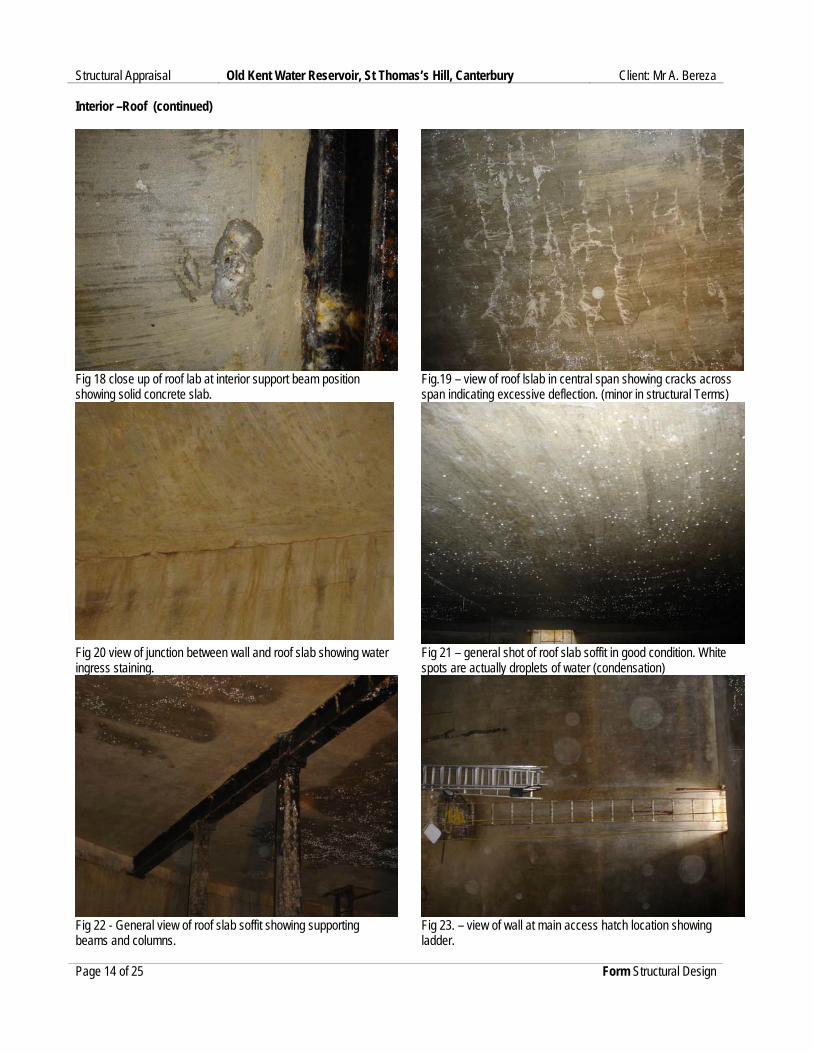
Fig.19 – view of roof lslab in central span showing cracks across span indicating excessive deflection. (minor in structural Terms)
Fig 20 view of junction between wall and roof slab showing water ingress staining.
Fig 21 – general shot of roof slab soffit in good condition. White spots are actually droplets of water (condensation)
Fig 22 - General view of roof slab soffit showing supporting beams and columns.
Fig 23. – view of wall at main access hatch location showing ladder.
Page 14 of 25 Form Structural Design

Structural Appraisal Old Kent Water Reservoir, St Thomas’s Hill, Canterbury Client: Mr A. Bereza Interior – Support structure – columns and beams.
Fig 24- View of roof slab soffit at wall / beam support junction – damp patches are condensation only
Fig 25 – Close up of wrought iron roof support beam and cast iron column head –white dots on roof soffit are condensation droplets.
Fig 26 – View of wrought iron roof support beam and cast iron column head –white dots on roof soffit are condensation droplets
Fig 27 - Close up of wrought iron roof support beam connections over cast iron column head
Fig 28 - Close up of wrought iron roof support beam connections over cast iron column head
Fig 29 - View of wrought iron roof support beam and cast iron column head showing minor corrosion to beam and column.
Page 15 of 25 Form Structural Design

Structural Appraisal Old Kent Water Reservoir, St Thomas’s Hill, Canterbury Client: Mr A. Bereza Interior – support structure (continued)
Fig 30 – Close up of typical cast iron column showing minor corrosion.
Fig 31 -– Close up of typical cast iron column base showing minor corrosion, seated on York stone pad on concrete plinth.
Fig 32 -– Close up of typical cast iron column base showing minor corrosion, seated on York stone pad on concrete plinth.
Fig 33 - View of typical cast iron column bases each side of 1250 high central concrete dividing wall.
Fig 34 - Close up of typical cast iron column base showing minor corrosion, seated on York stone pad on concrete plinth.
Fig 35 - Close up of typical cast iron column showing minor corrosion.
Page 16 of 25 Form Structural Design

Structural Appraisal Old Kent Water Reservoir, St Thomas’s Hill, Canterbury Client: Mr A. Bereza Interior – Support structure and base continued.
Fig 36 – View of central dividing wall showing steps up to access ladder.
Fig 37 – close up of 1250mm high central dividing wall showing steps up to access ladder.
Fig 38 - View of central dividing wall showing valve pit within base slab.
Fig 39 – General view of base slab showing typical column plinths and lime/clay silt deposits in layers from 4”-12” deep
Fig 40 – General view of base slab / wall junction showing lime/clay silt deposits in layers from 4”-12” deep over base.
Fig 41 – General view of base slab / central dividing wall showing lime/clay silt deposits in layers from 4”-12” deep over base.
Page 17 of 25 Form Structural Design

Structural Appraisal Old Kent Water Reservoir, St Thomas’s Hill, Canterbury Client: Mr A. Bereza Interior – Base / Walls
Fig 42 - – Close up of base slab / central dividing wall / colum plinths showing lime/clay silt deposits.
Fig 43 – Close up of wall showing 10mm thick waterproof render with saturated yellow clay bricks beyond.
Fig 44 – General shot of reservoir interior showing support structure and central dividing wall. Page 18 of 25 Form Structural Design

Structural Appraisal Old Kent Water Reservoir, St Thomas’s Hill, Canterbury Client: Mr A. Bereza 7.0 Measurement Survey Drawings Page 18 of 25 Form Structural Design


Structural Appraisal Old Kent Water Reservoir, St Thomas’s Hill, Canterbury Client: Mr A. Bereza 8.0 Historical Information (provided by Mid Kent Water Plc) Page 23 of 25 Form Structural Design