Embed Size (px)
Citation preview

,·-
I'
•
STRUCTURAL AND GEOCHEMICAL CONTROLS ON MINERALISATION AT
RENISON,. TASMANIA
Paul A. Kitto B.Sc. (Hans.) Dip. Ed.
Submitted in fulfilment of the requirements
for the degree of
Doctor of Philosophy
University of Tasmania

r ,.,
.... I
This thesis is dedicated to my wife Sue, and children Joel, Jillian and James
"Men who have excessive faith in their theories or ideas are not only ill prepared for making discoveries; they also make bad observations."
C. Bernard (1865)
ii

DECLARATION
This thesis contains no material which has been accepted or submitted for the award of any
other degree or diploma in any university, and to the best of my knowledge and belief,
contains no copy or paraphrase of material.published or written by another person, except
where due reference is made.
Paul A. Kitto,
University of Tasmania,
3rd November, 1994.
This thesis may be made available for loan. Copying of any part of this thesis is prohibited for
two years from the date this statement was signed; after that time limited copying is permitted
in accordance with the Copyright Act 1969.
p Paul A. Kitto
University of TAsmania
3rd November, 1994.
lll
ABSTRACT
Renison Tin Mine is located at Renison Bell; on the west coast of Tasmania. It is Australia's
largest primary tin producer, with an identified mineral resource totalling 9.5 mt at 1.4% Sn
and an annual production in 1993 of 580,000 t at 1.6% Sn (Thomas & Roberts, 1994). Total
Sn recovery since the commencement of large scale underground mining operations in the
1960's is over 115,000 t. Renison is hosted by subaerial to shallow marine, Late
Precambrian to Early Cambrian dolomitic and clastic sediments of the Early Palaeozoic
Dundas Trough. The deposit occurs on the north-east limb of a broad, south-east plunging
Devonian anticline which constitutes a major fault-bounded horst. Major brittle structures
associated with tin mineralisation at Renison formed during the forceful emplacement of the
Pine Hill Granite, include the Federal-Bassett Fault, Argent Fault, Blow Fault and a series of
east-west trending interconnected Transverse Faults.
The Pine Hill Granite forms a buried 'spine' that connects the Heemskirk and Granite Tor
Batholiths. The Pine Hill granite is classified as ilmenite-series, and is reduced (Fe3+;Fe2+
+ Fe3+ ratio of 0.14), peraluminous, and has corundum normative values between 0.8 and
1 .5. Plots of major, trace and REE analyses of the unaltered Pine Hill Granite show well
developed fractionation trends indicating approximately 60 % Rayleigh fractionation during
crystallisation. Beneath Renison, an apophysis of late stage quartz-feldspar porphyry granite
generated a high temperature boron and fluorine-rich fluid, which caused in-situ
sericitisation, albitisation and tourmalinisation.
Detailed study of kinematic indicators on mineralised faults has revealed four phases of
brittle deformation (Devonian to Tertiary), based on style and relative ages of fault striations.
Initial brittle deformation associated with the forceful emplacement of the Pine Hill Granite
formed the Federal-Bassett Fault, with up to 700m of normal-dextral dip-slip movement,
which allowed magmatic-hydrothermal fluids access to the dolomitic host sequence. A high
temperature oxide-silicate vein stage (qz-asp-cass) formed during this fault movement. Fluid
inclusions associated with this event have· homogenisation temperatures ranging from
>400°C at the base of the fault (3000 m beneath the Devonian palaeosurface), to 300°C
near the top of the mine workings. These early NaCI-KCI-H20 brines had average salinities
between -8 and 12 eq. wt.% NaCI, and fluid pressures of 250 bars (hydrostatic). o180tluid
values of 9 %o are clearly magmatic, consistent with a fluid which ascended and cooled with
the Federal-Bassett Fault before interacting with the wallrocks in the higher mine levels.
o34sfluid values from the oxide-silicate stage are< Groo and indicate the probable source of
sulphur is magmatic.
As the granite-related stress field decayed, a regional Taberraberran-related dextral wrench
reactivated earlier fault structures, and produced a dilational jog in the Federal-Bassett
1\'

Fault. This fault reactivation released a second generation of magmatic-hydrothermal fluids,
that ascended within the Federal-Bassett Fault and infiltrated the overlying dolomite
horizons. Main sulfide stage mineralisation (pyrrhotite+cassiterite-quartz-fluorite-stannite
chalcopyrite± arsenopyrite and minor base metals) produced the stratabound carbonate
replacement orebodies that characterise. the Renison deposit. During this stage of
mineralisation, mineral deposition in the Federal-Bassett Fault occurred over a temperature
range from <350°C, immediately above the Pine Hill Granite, to -200°C at the top of the
mine workings. The deep-level NaCI-KCI-H20-rich magmatic-hydrothermal brines evolved
to CaCI2·MgCI2-NaCI-H20-rich fluids during fluid-rock reactions with carbonates in the
upper mine levels. Salinities averaged between 8 and 12 eq. wt. % NaCI throughout the
sulphide stage. Contoured tin values and homogenisation temperatures from fluid inclusions
clearly outline two high temperature tin-rich dilational jogs on the Federal-Bassett Fault, as
do variations in a34smineral values. a34sfluid values remained constant at -5%o throughout
the sulphide stage, which is consistent with a homogeneous magmatic sulphur source.
Minor uneconomic base metal veins (rhodochrosite-galena-sphalerite-quartz}, associated
with late stage fault reactivations, overprint the earlier vein stages, as do vug-fill carbonate
quartz veins (quartz-carbonate±fluorite±pyrite). The late stage veins were associated with
low temperature (150° to 200°C), bimodal salinity (<2 and -10 eq. wt.% NaCI), NaCI-KCI
H20 brines that formed via mixing of contel!lporary meteoric groundwaters with magmatic
hydrothermal fluids. a34sfluid values (-5%o) remained unchanged, indicating that magmatic
fluid continued to supply sulphur to the Renison system over a protracted period. The only
fluid inclusion evidence for phase separation at Renison occurs in these late stage veins.
Fluid inclusion results from the oxide-silicate stage, in association with thermodynamic
modelling, provide the following estimates for initial magmatic-hydrothermal fluids at
Renison: -250 bars fluid pressure, -350°C temperature, salinity -12 eq. wt.% NaCI, pH 3.8
to 5.4, I.S = 0.05 molal, log 102 between -32.0 and -33.8, log JH2S between -0.5 and -2.5,
aH3As03 between 1 o-5 and 10-1, aNa+ = 0.1742, aK+ = 0.085, mMg2+ .between 1.6 x 1 o-5
and 6.2 x 10⁻², mca2+ between 7.96 x 10·3 ~nd 12.61, mf. between 1.05 x 1o-5 and 4.16 x
1 o-4, and Sn solubility = 20 ppm. Numerical simulations for this Renison-type oxide-silicate
stage fluid predict that boiling, cooling, and mixing with pure water (25°C} are inefficient
depositional mechanisms for precipitating cassiterite. In contrast, fluid-rock interaction
appears to be crucial for cassiterite deposition. Based on numerous simulations of fluid-rock
interaction, reaction with dolomite provides. the closest approximation of the actual oxide
silicate, sulphide stage and carbonate replacement mineral assemblages. Sn transport in
the Renison-type fluid was dominated by SnCI3" and Sn(OH)2CI2 complexes at 350°C and
logf02 =33.5, allowing the hydrothermal fluid to carry= 20 ppm I.Sn. At lower temperatures,
Sn(OH)2CI2 complexes became dominant. The most effective mechanism for cassiterite
v

deposition, as predicted by numerical modelling, was by redox and pH changes induced by
arsenopyrite deposition and carbonate dissolution, respectively.
In conclusion, distal skarn deposits like Renison, associated with carbonate replacement
mineralisation are intimately related to shallow mesothermal granitoids. The highly
fractionated and reduced ilmenite series granites acted as fertile sources for tin, which is
transported by magmatic-hydrothermal fluids from volatile-rich {B, F, Cl) apophyses in the
roof of the intrusion. Thermal metamorphism and forceful granite emplacement assisted
brittle deformation of the overlying host sequences allowing high temperature (300° to
400°C} acidic ore fluids access to reactive carbonate hosts. Cassiterite deposition is
controlled by fluid-rock interaction associated with redox changes induced by arsenopyrite
deposition, and by increased pH due to carbonate dissolution.
Vl

ABSTRACT
CONTENTS
TABLE OF CONTENTS
LIST OF FIGURES
LIST OF TABLES
LIST OF PLATES
ACKNOWLEDGEMENTS
CHAPTER 1 INTRODUCTION
1. 1 Preamble 1. 2 Renison Tin Mine 1. 3 Historical Production 1.4 Previous Geological Investigations 1.5 Present Study
CHAPTER 2 REGIONAL GEOLOGY AND STRATIGRAPHY
Page
iv
vii
xii
xvii
xviii
xix
1 1 3 3 5
2.1 Regional Geology and Structural Setting for Western Tasmania 6 2.1.1 Introduction 6 2.1.2 Regional Tectonics 6 2.1.3 Geology of the Renison District 9
2.2 Renison Stratigraphy 10 2.2.1 Success Creek Group 12 2.2.2 Crimson Creek Formation 15
2.3 Summary of Tectonic and Stratagraphic ~vents in the Renison District 16
CHAPTER 3 STRUCTURAL GEOLOGY OF RENISON
3.1 Introduction 3. 2 Pre-Tabberabberan Deformation 3. 3 Tabberabberan Deformation
3.3.1 Regional Devonian D1 Deformation 3.3.2 Devonian D1 Deformation at Renison 3.3.3 Regional Devonian D2 Deformation 3.3.4 Devonian D2 Deformation at Renison 3.3.5 Regional Devonian D3 Deformation 3.3.6 Devonian D3 Deformation at Renison
3.4 Brittle Deformation and Reactivation at Renison 3.4.1 Introduction 3.4.2 ·Method 3.4.3 Fault Striations 3.4.4 Normal-Dextral Faulting
3.4.4.1 Striation Analysis 3.4.4.2 Significance
3.4.5 Dextral Wrench Movement 3.4.5.1 Striation Analysis 3.4.5.2 Significance
3.4.6 Reverse-Sinistral Movement 3.4.6.1 Striation Analysis
18 18 19 19 19 19 20 21 21 22 22 23 23 23 23 27 31 31 31 35 35
Vll

Contents
3.4.6.2 Significance 3.4.7 Normal-Sinistral Movement
3.4.7.1 Striation Analysis. 3.4.7.2 Significance
3.4.8 Present-day Stresses 3.4.9 Summary of Brittle Deformation and Reactivation
3.5 Structural Controls to Mineralisation 3.5.1 Introduction 3.5.2 Method 3.5.3 Fault Structures and Mineralisation
3.5.3.1 First Order Structures Federal-Bassett Fault Blow Fault Complex
3.5.3.2 Second Order Structures Transverse Faults
3.5.3.3 Third Order Structures 3.5.3.4 Granite Topography
3.5.4 Summary of the Structural Controls to Mineralisation
CHAPTER 4 GEOLOGY AND GEOCHEMISTRY OF THE PINE HILL GRANITE
4.1 Introduction 4.2 Geological Setting
4.2.1 Morphology of the Pine Hill Granite 4.2.2 Petrography
4.2.2.1 Unaltered Granite · 4.2.2.2 Hydrothermal Alteration
4.3 Granite Geochemistry 4.3.1 Classification 4.3.2 Major, Trace and Rare Earth Elements
4.3.2.1 Major Element Geochemistry 4.3.2.2 Trace Element Geochemistry 4.3.2.3 Rare Earth Element Geochemistry
4.3.3 Geochemical Models of Crystal Fractionation 4.3.3.1 Major Element Models of Crystal Fractionation 4.3.3.2 Large Ion Lithophile Element Models of Crystal
Fractionation 4.3.4 Summary
4.4 Discussion: The Role of Volatiles in Sn(-W) Related Magmatic Hydrothemal Systems 4.4.1 Volatiles, Granitic Melts and Sn(-W) Mineralisation
4.4.1.1 Western Tasmanian Granitoids 4.4.1.2 The Role of Volatiles in Granite Metallogeny 4.4.1.3 The Association Between Volatile Release and
Western Tasmanian Sn-W Deposits
CHAPTER 5 MINERALOGY AND ALTERATION 5.1 Introduction 5. 2 Alteration in the Renison District
5.2.1 Thermal Metamorphism 5.2.2 Metasomatism
5.2.2.1 Greisen Zone 5.2.2.2 Skarn Zone - Summary of Skarn Mineralogy 5.2.2.3 Distal Alteration Features
5.2.3 Vein Assemblages
Page
35 35 35 37 37 37 39 39 40 44 44 44 47 48 48 53 53 57
60 60 63 67 67 70 71 71 74 76 76 78 78 80
82 83
84 84 86 87
90
93 93 93 95 97 99
100 101 102
Vlll

lX
Contents Page
5.3 Mineralisation in Renison-Dundas District 103 5.3.1 Overview of Renison-Dundas ·Mineral Field 103 5.3.2 Structural Controls to Mineralisation 106 5.3.3 Tin Deposits 111 5.3.4 Copper Deposits 115 5.3.5 Lead-Zinc Deposits 115
,..,.. 5.4 Mineralisation at Renison 116 5.4.1 Major Styles of Mineralisation 116
5.4.1.1 Stratabound Carbonate Replacement Mineralisation 118 5.4.1.2 Fault Mineralisation 124
(i) Fault Ore 124 (ii) Stratafault Ore 124
5.4.1.3 Fracture Ore 126 5.4.2 Vein Paragenesis and Deformation of the Renison Ores 126
5.4.2.1 Previous Investigations 128 5.4.2.2 Links Between Deformation and Vein Paragenesis 128 5.4.2.3 Oxide-silicate Stage 130 5.4.2.4 Main Sulphide Stage 132 5.4.2.5 Late Base Metal Stage 134 5.4.2.6 Vug-fill Carbonate Stage 134 5.4.2. 7 Supergene Stage 137
5.4.3 Renison Ore Microscopy 137 5.4.4 Metal Distribution on Faults at Renison 153
5.5.4.1 Metal Distribution on the Federal-Bassett Fault 153 5.5.4.2 Metal Distribution on 'Shear P' 160 5.5.4.3 Metal Distribution on 'Shear L' 160
5.5 Summary 163
CHAPTER 6 FLUID INCLUSION STUDIES
6.1 Introduction 166 6.2 Methods of Study 166 6.3 Classification of Fluid Inclusion Types 168 6.4 Fluid Inclusion Petrography 171
I 6.4.1 Fluid Inclusions In Cassiterite 171 6.4.2 Fluid Inclusions In Quartz 172 • 6.4.3 Fluid Inclusions In Fluorite 172 6.4.4 Fluid Inclusions In Carbonate 173
6.5 Fluid Inclusion Microthermometry 173 6.5.1 Oxide-silicate Stage Fluid Inclusions 173 6.5.2 Sulphide Stage Fluid Inclusions 175 6.5.3 Base Metal Stage Fluid Incl\lsions 178
~ 6.5.4 Carbonate Stage Fluid Inclusions 181 6.6 Discussion 184
6.6.1 Spacial Evolution of the Mineralising Fluids 184 6. 6.1.1 Oxide-silicate Stage 184 6.6.1.2 Sulphide Stage 184 6.6.1.3 Base Metal and Carbonate Stages 188
6.6.2 Temporal Variation In Hydrothermal Fluids 188 6.6.3 Chemical Evolution of the Mineralising Fluids 190 6.6.4 Pressure-Depth Estimates 194
6.6.4.1 Pressure Corrections 195 6.6.5 Evidence for Phase Separation 195 6.6.6 C02 Concentrations 196
6.7 Summary and Conclusions 196

~·
Contents
CHAPTER 7 SULPHUR ISOTOPE GEOCHEMISTRY
7.1 Introduction 7.2 Previous Isotope Investigations 7.3 This Study 7.4 Analytical Techniques 7.5 Sulphur Isotope Results
7 .5.1 Oxide-silicate Stage 7.5.2 Main Sulphide Stage 7.5.3 Base Metal Stage 7.5.4 Vug-fill Carbonate Stage 7.5.5 Supergene Stage 7.5.6 Renison-Dundas District
7.6 Discussion Of Sulphur Isotope Results 7 .6.1 Oxide-silicate Stage 7.6.2 Main Sulphide Stage 7 .6.3 Base Metal Stage 7 .6.4 Renison-Dundas District
7.7 Summary and Conclusions 7. 8 Future Areas for Research
Page
199 199 200 200 204 204 204 206 207 207 207 208 208 210 213 215 216 218
CHAPTER 8 OXYGEN AND CARBON ISOTOPE GEOCHEMISTRY
8.1 8.2
8.3
Introduction Oxygen Isotopes in Quartz 8.2.1 Previous Investigations 8.2.2 Analytical Techniques 8.2.3 Results
8.2.3.1 Pine Hill Granite 8.2.3.2 Oxide-silicate Stage 8.2.3.3 Renison-Dundas District
8.2.4 Discussion 8.2.4.1 Pine Hill Granite 8.2.4.2 Oxide-silicate Stage 8.2.4.3 Renison-Dundas District
8.2.5 Summary and Conclusions 8.2.6 Future Areas For 8180qz Research Oxygen and Carbon Isotopes: Fluid-rock interaction in the Renison carbonates 8.3.1 Introduction 8.3.2 Previous Investigations 8.3.3 Results 8.3.4 Fluid-Rock Interaction 8.3.5 Fluid Infiltration Mechanisms 8.3.6 Finite Difference Models For Fluid-Rock Interaction 8.3.7 Conclusions 8.3.8 Areas For Future 8180 - 813C Research
220 220 221 221 222 222 222 226 226 226 226 229 229 231
232 232 232 233 238 239 246 247
CHAPTER 9 THERMODYNAMIC CONSTRAINTS AND MODELS FOR ORE DEPOSITION
9.1 Introduction 249 9.2 Thermochemical Environment For Ore Deposition 249
9.2.1 Temperature, Pressure, Composition and Salinity 250 9.2.2 Mineral-Solution Equilibria 250 9.2.3 fH2S, J02 (fH2) and Tota\ Sulphur 253
X

Contents Page
9.2.4 Sn Speciation 9.2.5 Summary: Composition Of The Ore-fonning Fluid
9.3 Numerical Simulations For Ore Deposition 9.3.1 -Methods of Calculation 9.3.2 Physico-chemical Conditions Of The Renison-type Fluid 9.3.3 Results
9.3.3.1 Cooling Simulations
9.3.3.2 Boiling Simulations 9.3.3.3 Fluid Mixing Simulations 9.3.3.4 Rock Titrations
Dolomite Titrations Other Rock Titrations
9.3.4 Summary 9.4 Conclusions
CHAPTER 10 CONCLUSIONS: A GENETIC MODEL FOR THE RENISON MAGMATIC HYDROTHERMAL SYSTEM
259 259 262 262 263 265 265
268 270 272 272 276 277 278
10.1 Introduction 280 10.2 Evolutionary History of the Pine Hill Granite and Renison
Hydrothermal System 281 10.3 Future Areas For Research 287
REFERENCES ~9
APPENDENCES
APPENDIX I
APPENDIX II
Renison Mine Cross-sections
Granite Geochemistry Data
308
401
APPENDIX III Metal Accumulation Diagrams- Federal-Bassett Fault 411
APPENDIX IV Metal Accumulation Diagrams- Shear P
APPENDIX V Metal Accumulation Diagrams- Shear L
APPENDIX VI Fluid Inclusion Data
APPENDIX VII Sulphur Isotope Data
APPENDIX VIII Carbon and Oxygen Isotope Data
413
415
417
430
437
APPENDIX IX Fluid-Rock Program For Carbon-Oxygen isotopes 441
APPENDIX X Pixe Probe Data 446
APPENDIX XI Modified Soltherm Database 448
APPENDIX XII Renison Rock Catalogue 467
XI

Xll
·LIST OF FIGURES Figure Page
1.1 Regional geology of western Tasmania 2
2.1 Western Tasmanian geology 7
2.2 Geological interpretation of the Renison district 11
2.3 Stratigraphy of the Renison mine sequence 13
3.1 Criteria used to determine sense of displacement on fault surfaces 25
3.2 Lower hemisphere equal area projections of fault striations compatible
with normal-dextral movement on the Federal-Bassett Fault 26
3.3 Lower hemisphere equal area projections of principal compressive
stress directions compatible with normal-dextral movement on the
Federal-Bassett Fault 28
3.4 Orientation of folds, thrusts, normal faults, and Riedel shears 30
3.5 Lower hemisphere equal area projections of the Federal-Bassett Fault
the secondary reverse structures 30
3.6 Lower hemisphere equal area projections of fault striations and calculated
principle compressive stresses compatible with dextral wrench on the
Federal-Bassett Fault 32
3.7 Lower hemisphere equal area projections of fault striations and
calculated principle compressive stresses compatible with reverse-
sinistral reactivation on the Federal-Bassett Fault 36
3.8 Lower hemisphere equal area projections of fault striations and
I calculated principle compressive stresses compatible with normal-
sinistral reactivation on the Federal-Bassett Fault 38 ~ 3.9 Regional cross-section of the Renison district 41
3.10 Renison cross-section at 65820N 42
3.11 Geological interpretation of the Renison Mine area showing the
stratigraphy and major fault structures 43
3.12 Generalised cross-section of a faulted monocline and associated
structure compared to the North Bassett area at 67000N 45
3.13 Cross-section and reconstruction of the North Bassett area at 67060N 46
3.14 Footwall projection of the No. 3 Dolomite horizon 49
3.15 Isometric projection of Shear P 51
3.16 Cross-section of the Polaris ore body at 66440N 52
3.17 Cross-section and reconstruction of the the mine area at 65740N 54
3.18 Contours for the Pine Hill Granite beneath Renison and the associated
fault structures in the Renison mine area 56
List of Figures cont. Page
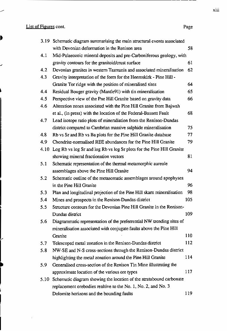
3.19 Schematic diagram summarising the main structural events associated
with Devonian deformation in the Renison area 58
4.1 Mid-Palaeozoic mineral deposits and pre-Carboniferous geology, with
gravity contours for the granitoid/crust surface 61
4.2 Devonian granites in western Tasmania and associated mineralisation 62
4.3 Gravity interpretation of the form for the Heemskirk - Pine Hill -
Granite Tor ridge with the position of mineralised sites 64
4.4 Residual Bouger gravity (Mantle91) with tin mineralisation 65
4.5 Perspective view of the Pne Hill Granite based on gravity data 66
4.6 Alteration zones associated with the Pine Hill Granite from Bajwah
et al., (in press) with the location of the Federal-Bassett Fault 68
4. 7 Lead isotope ratio plots of mineraliation from the Renison-Dundas
district compared to Cambrian massive sulphide mineralisation 75
4.8 Rb vs Sr and Rb vs Ba plots for the Pine Hill Granite database 77
4.9 Chondrite-normalised REE abundances for the Pine Hill Granite 79
4.10 Log Rb vs log Sr and log Rb vs log Sr plots for the Pine Hill Granite
showing mineral fractionation vectors 81
5. 1 Schematic representation of the thermal metamorphic aureole
assemblages above the Pine Hill Granite 94
5.2 Schematic outline of the metasomatic assemblages around apophyses
in the Pine Hill Granite 96
5. 3 Plan and longitudinal projection of the Pine Hill skarn mineralisation 98
5.4 Mines and prospects in the Renison-Dundas district 105
5.5 Structure contours for the Devonian Pine Hill Granite in the Renison-
Dundas district 109
5. 6 Diagrammatic representation of the preferrential NW trending sites of
mineralisation associated with conjugate faults above the Pine Hill
Granite 110
5.7
5.8
Telescoped metal zonation in the Renison-Dundas district
NW-SE and N-S cross-sections through the Renison-Dundas district
112
highlighting the metal zonation around the Pine Hill Granite 114
5.9 Generalised cross-section of the Renison Tin Mine illustrating the
approximate location of the various ore types 117
5.10 Schematic diagram showing the location of the stratabound carbonate
replacement orebodies realtive to the No. 1, No.2, and No.3
Dolomite horizons and the bounding faults 119
Xlll

List of Figures cont. Page
5.11 Footwall projection of the No. 1 Dolomite horizon 120
5.12 Footwall projection of the No.2 Dolomite horizon 121
5.13 Plot of total sulphur vs MgO (wt%) for the stratabound carbonate
replacement orebodies 125
5.14 Longitudinal projection of the Federal-Bassett Fault showing the location
of the stratafault and Rendeep ore bodies 127
5.15 Mineralogy, vein paragenesis and deformation relationships for the
Federal-Bassett Fault mineralisation 129
5.16 Major structural irregularities controlling mineralisation along the
Federal-Bassett Fault 154
5.17 Sn accumulation diagram for the Federal-Bassett Fault, with overlay 156
5.18 W accumulation diagram for the Federal-Bassett Fault 158
5.19 Ag accumulation diagram for the Federal-Bassett Fault 159
5.20 Isometric projection of Shear P with Sn accumulation plotted 161
5.21 Isometric projection of Shear L with Sn accumulation plotted 162
6.1 Histograms of homogenisation and salinity data for oxide-silicate
stage fluid inclusions 174
6.2 First melting temperatures for oxide-silicate stage fluid inclusions 176
6. 3 Histograms of homogenisation and ·salinity data for main sulphide
stage fluid inclusions 177
6.4 First melting temperatures for main sulphide stage fluid inclusions 179
6.5 Histograms of homogenisation and salinity data for base metal
stage fluid inclusions 180
6.6 First melting temperatures for base metal and carbonate stage fluid
inclusions
6. 7 Histograms of homogenisation and salinity data for carbonate
stage fluid inclusions
182
183
6. 8 Distribution of fluid inclusion homogenisation temperatures for the
oxide-silicate stage of mineralisation along the Federal-Bassett Fault 185
6.9 Distribution of fluid inclusion homogenisation temperatures for the
main sulphide stage of mineralisation along the Federal-Bassett Fault 186
6.10 Distribution of fluid inclusion homogenisation temperatures for the
base metal and carbonate stages of mineralisation along the Federal-
Bassett Fault 187
6.11 Salinity vs homogenisation temperatures for the vein stages of
mineralisation along the Federal-Bassett Fault 189
xiv
List of Figures cont.
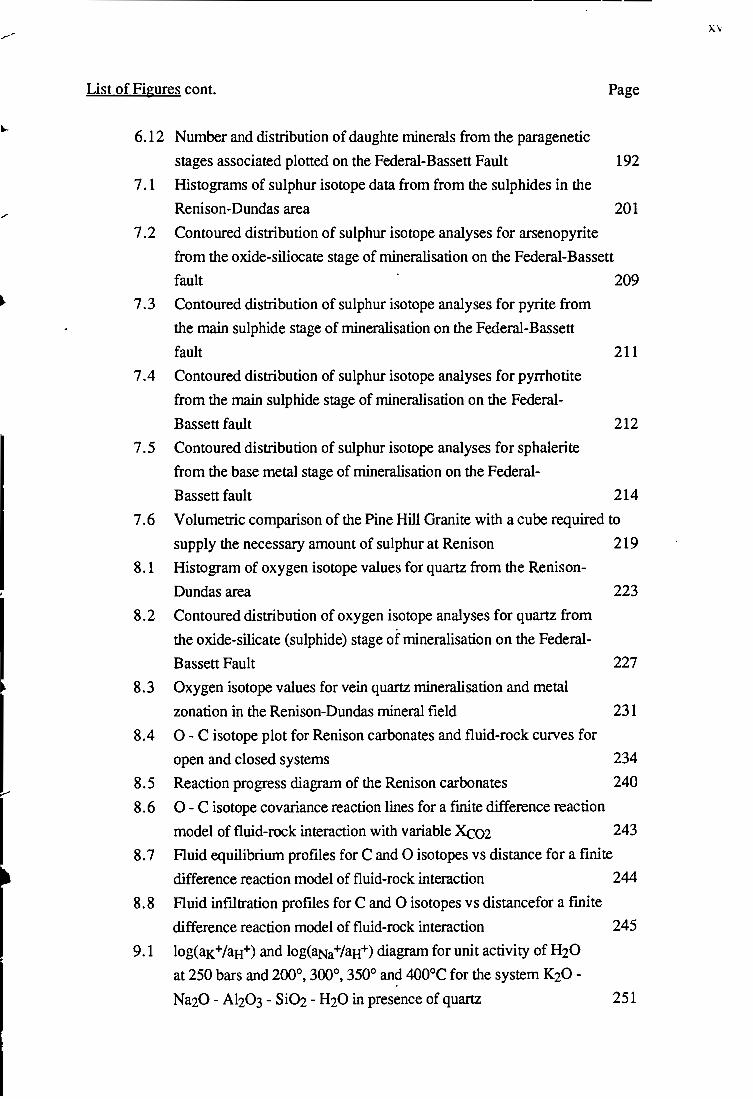
6.12 Number and distribution of daughte minerals from the paragenetic
stages associated plotted on the Federal-Bassett Fault
7.1 Histograms of sulphur isotope data from from the sulphides in the
Renison-Dundas area
Page
192
201
7.2 Contoured distribution of sulphur isotope analyses for arsenopyrite
from the oxide-siliocate stage of mineralisation on the Federal-Bassett
fault 209
7. 3 Contoured distribution of sulphur isotope analyses for pyrite from
the main sulphide stage of mineralisation on the Federal-Bassett
fault 211
7.4 Contoured distribution of sulphur isotope analyses for pyrrhotite
from the main sulphide stage of mineralisation on the Federal-
Bassett fault
7.5 Contoured distribution of sulphur isotope analyses for sphalerite
from the base metal stage of mineralisation on the Federal
Bassett fault
212
214
7. 6 Volumetric comparison of the Pine Hill Granite with a cube required to
supply the necessary amount of sulphur at Renison 219
8.1 Histogram of oxygen isotope values for quartz from the Renison-
Dundas area 223
8.2 Contoured distribution of oxygen isotope analyses for quartz from
the oxide-silicate (sulphide) stage of mineralisation on the Federal-
Bassett Fault
8.3 Oxygen isotope values for vein quartz mineralisation and metal
zonation in the Renison-Dundas mineral field
8.4 0- C isotope plot for Renison carbonates and fluid-rock curves for
open and closed systems
8.5
8.6
Reaction progress diagram of the Renison carbonates
0 - C isotope covariance reaction lines for a finite difference reaction
227
231
234
240
model of fluid-rock interaction with variable Xco2 243
8.7 Fluid equilibrium profiles for C and 0 isotopes vs distance for a finite
difference reaction model of fluid-rock interaction 244
8.8 Fluid infiltration profiles for C and 0 isotopes vs distancefor a fmite
difference reaction model of fluid-rock interaction 245
9.1 log(aK+faH+) and log(aNa+faH+) diagram for unit activity of H20
at 250 bars and 200°, 300°, 350° an~ 400°C for the system K20-
251
X\

List of Figures cont.
9.2 log(aK+faH+) and log(aMgZ+faZH+) diagram for unit activity of HzO
at 250 bars and 200°,300°, 350° and 400°C for the system KzO-
Page
KzO - Alz0:3 - SiOz - HzO in presence of quartz 252
9.3 log(acaZ+faZH+) and log(aMgZ+faZH+) diagram for unit activity of HzO
at 250 bars and 200°,300°, 350° and 400°C for the system CaO-
MgO - SiOz - HzO in presence of quartz 254
9.4 log(aK+faH+) and log(aH+fap-) diagram for unit activity ofHzO
at 250 bars and 200°, 300°, 350° and 400°C for the system KzO-
Alz03 - SiOz - HF - HzO in presence of quartz
9.5 Superimposed phase relations in the system SnO- HzS- HzO
Hz and FeO - HzS - HzO -Hz as a function of the fugacitites of
H2S and H2 for unit activity of water at 250 bars and 200°, 300°,
255
350° and 400°C 256
9.6 Speciation diagrams showing the predominance fields of sulphur-bearing
species in the oxide-silicate stage as a function of Hz and pH 258
9. 7 logf02 - pH diagram at 350°C and 250 bars showing solubility
contours for Sn and As, the predominance fields for Sn(OH)2Cl2
and SnC13-, and the stability fields for cassiterite and herzenbergite 260
9. 8 Flow diagram of the 25 simulations of depositionsal processes for
cassiterite deposition (cooling, boiling, mixing, water-rock
interaction) 266
9.9 Cooling simualtions from 350° to 150°C of a Renison-type oxide-
silicate stage fluid 267
9.10 Isoenthalpic boiling simulations of a Renison-type oxide-
silicate stage fluid from 350°C to 150°C
9.11 Mixing of the hypothetical350°C Renison-type oxide-
silicate stage fluid with 25°C pure water
9.12 Reaction of the hypothetical350°C Renison-type oxide-silicate
stage fluid with an average Renison dolomite
10.1 Schematic model for the formation of the major tin-rich
hydrothermal systernat Renison
269
271
273
282
XY1

LIST OF TABLES
3.1 Principle stress directions calculated from fault striations
3.2 Present-day stress magnitudes and orientations
Page
28
28
4.1 Composition of representative geochemical analyses for the Pine Hill
Granite and averaged compositions for the S-type granites from the
4.2
4.3
4.4
4.5
4.6
5.1
5.2
5.3
6.1
6.2
6.3
7.1
7.2
Lachlan Fold Belt 72
Summary of the geochemical characteristics of the Pine Hill Granite 73
Major element modelling of crystal fractionation for the unaltered Pine
Hill Granite 80
Genetic associations between Sn and W deposits in western Tasmania 85
The effects of chlorine, fluorine and boron on granitic melts 88
Summary of the characteristics associated with typical Sn and W
related granitoids in western Tasmania 91
Types of mineralisation mined in the Renison-Dundas district 104
Prospects and mines in the Renison-Dundas mineral field, and a list of
their styles of mineralisation 107
Prospects and mines in the Renison-Dundas mineral field, and a list of
their mineralogies 108
Summary of fluid inclusion types, the phase(s) present at 25°C, and the
high temperature homogenisation behaviour 169
Summary of the fluid inclusion data from the Federal-Bassett Fault 171
First melting temperatures of eutectics for a number of salt-H20
systems 191
Summary of sulphur isotope statistics for each paragenetic stage associate
with fault controlled mineralisation at Renison 203
Calculated 834Sl:s for the hydrothermal fluids associated with the
sulphide stages within the Federal-Bassett Fault 217
8.1 ~)180qz for the Pine Hill Granite samples 224
8.2 ()180qz for the oxide-silicate (sulphide) stage mineralisation on the
Federal-Bassett Fault 224
8. 3 ()180qz for the oxide-silicate (sulphide) stage mineralisation on the
Transverse Faults 225
8.4 ()180qz for main stage mineralisation, Renison-Dundas district 225
9.1 Estimates of the physico-chemical conditions associated with tin
transportation and deposition at Renison 261
9.2 Composition of a potential350°C Renison-type fluid 264
9.3 Average composition for a number of host lithologies at Renison 274
XVll
xviii
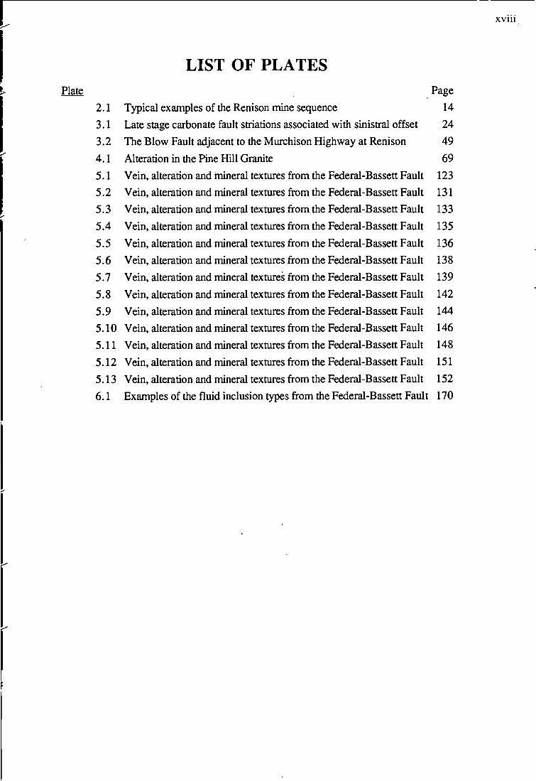
LIST OF PLATES
~ Plate Page
2.1 Typical examples of the Renison mine sequence 14 3.1 Late stage carbonate fault striations associated with sinistral offset 24 3.2 The Blow Fault adjacent to the Murchison Highway at Renison 49 4.1 Alteration in the Pine Hill Granite 69 5.1 Vein, alteration and mineral textures from the Federal-Bassett Fault 123 5.2 Vein, alteration and mineral textures from the Federal-Bassett Fault 131 5.3 Vein, alteration and mineral textures from the Federal-Bassett Fault 133 5.4 Vein, alteration and mineral textures from the Federal-Bassett Fault 135 5.5 Vein, alteration and mineral textures from the Federal-Bassett Fault 136 5.6 Vein, alteration and mineral textures from the Federal-Bassett Fault 138 5.7 Vein, alteration and mineral textures from the Federal-Bassett Fault 139
5.8 Vein, alteration and mineral textures from the Federal-Bassett Fault 142
5.9 Vein, alteration and mineral textures from the Federal-Bassett Fault 144 5.10 Vein, alteration and mineral textures from the Federal-Bassett Fault 146 5.11 Vein, alteration and mineral textures from the Federal-Bassett Fault 148
5.12 Vein, alteration and mineral textures from the Federal-Bassett Fault 151
5.13 Vein, alteration and mineral textures from the Federal-Bassett Fault 152
6.1 Examples of the fluid inclusion types from the Federal-Bassett Fault 170

ACKNOWLEDGEMENTS
First and foremost, I thank my wife Sue for all her love, patience and sacrifice to bring this
thesis to fruition, and to our children Joel, Jillian and James, who have coped with a
graduate father and all the attendant difficulties.
I would very much like to express my gratitude to my supervisors, Prof. Ross R. Large, and
Drs. Ron F. Berry and David R. Cooke. All three supervisors have provided guidance,
assistance, patience and helpful suggestions throughout the course of this thesis. Ross
provided the initial encouragement and financial assistance through a Tasmanian
Government Scholarship to return from the work force. His positive approach and drive has
been inspirational. Ron initiated the structural investigations which provide the framework for
the entire thesis and has been the font of all knowledge when problems seem
unsurmountable. The efforts of Dave have been heroic, and his advice and encouragement
cannot be overstated. Without Dave at the helm a large proportion of this thesis would not
·have been possible and I will always be eternally grateful to him for his dedication and
committment to my research.
My research at Renison would not have been possible without the support and
encouragement of the former Superintendent of Technical Survices at Renison, Colin
Cannard. His foresight, enthusiasm and financial support for this project made it happen.
The geological community at Renison have been most supportive of this study and given
freely of their time to discuss ideas. The Chief Geologist Ray Roberts is thanked for his
continued encouragement, assistance and financial support. Scott Dunham should be given
a pay rise for all his time and effort. Without his unflagging efforts at the computer terminal
my interpretations of the Renison geology would not have been possible. Many thanks go to
Bruce McQuitty who has given freely of his vast knowledge of the Renison system and
continually gone out of his way to assist where possible. A number of past and present
employees of Renison also deserve recognition for their friendship and help: Mark Csar,
Mark Hall, Jono Lee, John Tyrrell, Tim Callaghan, Mat Bampton, Pat McMullen, Gareth
Thomas, Peter 'K', Tony Wiggins, Andrew Bruce, John and Vicki, Mick McKeown and Mike
Seeker.
Technical help and advice on a variety of problems have been provided by a number of
wonderful people including: June Pongratz, Christine Higgins, Peter Cornish, Jeanette
Hankin, Sue Hinksman, Simon Stephens, Naomi .Oeards, Mike Power, .Kathi Stait, Phil
Robinson, Neila Hlaing, Gerrit Kuipers, Neil McNaughton, Kirsty Whaley, Wieslaw Jablonski,
Fred Koolhof, Debbie Harding, and Vagn Jensen. A very large thank you goes to Mike
xix.

Roach for his friendship and endless hours of unselfish work on the computer. Thanks also
to Andrew (Bear) McNeil for assisting with microprobe analyses.
There have been times when brief discussions with various people have proven of great
benefit to me during the course of this study. They are: Drs. Garry Davidson, Bruce
Gemmell, Joe Stolz, Khin Zaw, Geoff Green, Richard Keele, Dave Huston, Mike Solomon,
John Walshe, Scott Halley, Peter Pollard, Gregg Morrison, Jim Reynolds, Dave Patterson,
Dick Hutchinson, Roger Marjoribanks, Dave Whitford, Brian Gulson, Mel Jones, lan
Cartwright and Zia Bajwah.
Throughout the progress of this thesis the staff and students of The Centre for Ore Deposits
and Exploration Studies (CODES) and the Geology Department at the University of
Tasmania have provided endless hours of fun and friendship. Thanks to everyone for
sharing your life and good times, especially (in no particular order) Greg Yaxley, lngvar
Sigurdson, Anthea Hill, Ruth Lanyon, Dave Selley, Andrew Tunks, Jamie Rogers, Steve
Hunns, Marcel Kamperman, Kim Hein, Sampan Singharajwarapan, Mat White, Lachlan
Heasman, Singoyi Blackwell, Steve Boden, Andrew Wellington, James Cannell, Mike
Roache, Stuart Smith, Karen Orth, Mark Doyle, Stuart Bull, Peter McGoldrick, Jocelyn
McPhie, Tony Crawford, Steve Abbott, Nathan Duhig, Fernando Della-Pasqua, Andrew
Jones, Peter Rice, Mark Duffett, Prasada Rao, Mohammad Adabi and anyone else I've
forgotten to mention. A very special thank you to Alicia Verbeeten and Rohan Hind for their
kindness in collating this thesis.
XX

I.
CHAPTER 1: INTRODUCTION
1.1 PREAMBLE •••
Detailed studies linking both structural and geochemical investigations associated with ore
deposition are rarely reported in the literature. As Renison represents the world's largest
operating underground tin mine it provides a unique opportunity to investigate a large,
accessible, and economic palaeo-hydrothermal tin-rich system. This thesis aims to present a
model for tin deposition at Renison based on an integrated approach to ore deposit
research. The model developed for Renison highlights the intimate associations between:
granite evolution and granite emplacement; the structural preparation of the accompanying
hostrocks; the geochemical evolution of the hydrothermal system; and the likely
mechanisms for cassiterite deposition resulting in the formation of a Sn-rich world-class
stratabound carbonate replacement deposit.
1.2 RENISON TIN MINE •••
Renison, Australia's largest primary tin producer, is located at Renison Bell on the west coast
of Tasmania, at longitude 145°26'E and latitude 41 °48'S (Queenstown SK 55-5, 1 :250 000
sheet). The mine is 136 km south of the port of Burnie, 10 km west of the mining town of
Rosebery, and 16 km north-east of the town of Zeehan (Figure 1.1 ).
The deposit occurs within the longitudinal Palaeozoic Dundas Trough, bounded by the
Proterozoic Tyennan and Rocky Cape metasediments (Solomon, 1981 ). Carbonate
horizons hosting replacement mineralisation lie within the subaerial to shallow marine, Late
Precambrian to Early Cambrian Success Creek Formation (Corbett eta/., 1987) and shallow
marine Early Cambrian Crimson Creek Formation (Kitto, 1990). Forceful emplacement of an
asymmetrical granite ridge associated with the Devonian Pine Hill Granite (355 ± 4 Ma:
Brooks, 1966) resulted in a complex brittle deformation of the host rocks (Kitto, 1990 &
1992; Kitto and Berry, 1991 & 1992) providing a major focus for ascending hydrothermal
fluids that resulted in tin-rich carbonate replacement and vein styles of mineralisation.
Renison is the largest of three major stratabound, carbonate replacement, pyrrhotite
cassiterite deposits in western Tasmania. The other two occur at Mt. Bischoff (Groves et al,
1972; Wright, 1986; Halley, 1987) and at Cleveland (Collins, 1981). Such primary tin
1

SCALE
0 10 20 ~ 40
OO~@a@~~~ @~@~@@W
@~
W[§®if[§OOOO If ~®fM~~a~
LEGEND:
POST-CAMBRIAN COVER
DEVONIAN ACID INTRUSIVES
PROTEROZOIC METASEDIMENTS
SEDIMENTS } LATE PROTEROZOIC TO CAMBRIAN ~~
VOLCANICS
Figure 1.1 Regional geology of western Tasmania, showing the location of the Renison
mine together with other major mineral deposits (modified after Moreland,
1988).
2

deposits represent ideal exploration targets because of their above average tonnage-grade
characteristics (Menzies eta/., 1988; Premoli, 1988).
1.3 HISTORICAL PRODUCTION •••
In 1890, Ringrose Nicholson discovered alluvial and gossanous cassiterite deposits at
Renison, then known as the North Dundas Mineral Field (Montgomery, 1893). At that time
George Renison Bell held prospecting claims for silver and lead along the Argent River west
of Renison (Moreland, 1990).
The discovery of cassiterite-sulphide ore occurred in 1900 during construction of the Emu
Bay Railway, but processing of the tin-bearing gossan and oxidised sulphide ore only began
in 1905. The total Sn production prior to this was estimated at 200 tonnes. Several small
companies were formed to treat oxidised sulphide in the first mill, erected in 1907. By 1914
the dominant production was from oxidised sulphides. Hard rock mining ceased in the
1920's when only untreatable massive iron sulphide remained. Between 1925 and 1935 the
mineral field went into decline and eventual abandonment as surface deposits were
depleted.
In 1936, most of the smaller leases amalgamated to form Renison Associated Tin Mines as
technology overcame the difficulty of recovering tin from massive pyrrhotite by flotation.
Consequently, small scale open-cut and underground mining resumed, but production
remained low (50- 100 tonnes Sn per annum; Blissett, 1962).
Exploration in the late 1950's defined a potentially major orebody and in 1960 the "Mt. Lyell
Mining and Railway Company acquired control of Renison Associated Tin Mines. Mining of
the Federal orebody commenced in 1960 closely followed by the discovery of additional
reserves ·of "sill ore" (Moreland, 1986).
_Commissioning of a new concentrator in _1967 hailed the beginnings of large scale
underground mining operations at Renison. In 1993 Renison had an annual production rate
of 577,200 tonnes at 1.6% Sn and an identified mineral resource totalling 9.5 million tonnes
at -1.4% Sn (Thomas & Roberts, 1994). Production figures since 1960 record that the total
recovery of Sn has exceeded 115,000 t.
1.4 PREVIOUS GEOLOGICAL INVESTIGATIONS
A plethora of information on the Renison mine geology has been generated since the
commencement of mining operations in the district. Initial descriptions of the tin deposits in
the Renison area were undertaken by Waller (1902), Ward (1909), Herman (1914) and
3

Conder (1918), but it was Stillwell and Edwards (1943) who provided the first detailed
account of ore microscopy at the Renison Mine. Fisher (1943) considered the sulphide
sheets to be a dilational displacement of the en.closing sedimentary beds by the mineralising
solutions, but Hall and Solomon (1962) suggested mineralisation represented stratabound
carbonate replacement styles analogous to Mt Bischoff. Carey (1953) had previously linked
mineralisation at Renison with the intrusion of the Pine Hill Granite. Blissett (1962) reviewed
the history of exploration and geological investigations in the North Dundas Mineral Field
(Renison district) before the 1960's. GiHillan (1965), Groves (1968) and Collins (1972)
provided comprehensive descriptions of the geology and mineralogy of the Renison Bell
area, and concluded the sulphide-cassiterite ore was formed by replacement of the
carbonate horizons. Hill & Haynes (1969) and Haynes & Hill (1970) undertook detailed
geochemical and mineralogical investigations of the pyrrhotite-pyrite phases and
relationships of the stratabound ore. In his doctoral thesis on the geological setting and
mineralisation at Renison Patterson (1979) outlined the advancements in geological
understanding in the intervening twenty year period since Blissett (1962). Hutchinson
(1979, 1981, 1982) and Plimer (1980) in discussing the mineralogical and geological setting
for Renison proposed an exhalative origin for the cassiterite-sulphide mineralisation but
Solomon (1980), Newnham (1981) and Patterson (1982) have argued against this proposal.
Ward (1981) and Bajwah eta/. (in press) examined the mineralogy and alteration of the Pine
Hill Granite suite, and Manly (1982) complemented these studies by an investigation of the
contact skarns adjacent to the apex of Pine Hill. Hutton (1976) and Djakic (1981) looked at
the environment of deposition for the Red Rock Member. Davies (1985) researched the
mechanisms of stratabound replacement mineralisation and Holyland (1987) proposed
structural and hydrodynamic models for the Renison Tin Mine. Simonsen (1988) and Barber
{1990) undertook a study of the structure and geochemistry of the Polaris orebody and
Haines ( 1991) reviewed the stratigraphy of the Lower Crimson Creek Formation in the
Renison Bell area.
Renison has also commissioned a number of academic investigations on an in-house and
contractual basis. W. H. Fander has described the mineralogy of the Renison ores in a
number of unpublished petrological reports to the company. Morrison (1982 & 1993)
defined a working stratigraphy for the Renison Mine Sequence; Jones and Evans (1985)
examined the trace element and stable isotope variations in the Mine Sequence rocks;
Leaman (1990) undertook a gravity survey to interpret the form of the Pine Hill Granite;
Marjoribanks {1989 & 1990) attempted to place the mine structure into a regional context;
Lea (1991) summarised the exploration potential of the Renison mine lease; and Kitto
(1993b) detailed exploration criteria for Renison style deposits and made recommendations
for the mine lease.
4

1.5 PRESENT STUDY
This investigation attempts to unravel the complex structural history of the .Renison area and
quantify the source(s), pathways and chemical evolution of hydrothermal fluids responsible
for mineralisation.
The integrated investigative approach has involved studying kinematic indicators on major
fault surfaces to assess the history of brittle deformation and associated stresses. 20 m
spaced 1:2000 scaled cross-sections over a 2 km strike length of the Renison Mine were
produced to assist interpretations of the structural controls to mineralisation.
A review of the Pine Hill Granite geomorphology, geochemistry and alteration has been
undertaken to assist interpretations of the spatial and temporal distribution of alteration and
mineralisation in the Renison-Dundas district. Within the mine area, petrological, fluid
inclusion and isotope studies were used to estimate the physico-chemical conditions for
vein and carbonate replacement styles of mineralisation.
Static thermodynamic modelling was undertaken to constrain the physico-chemical
conditions of ore deposition. Numerical modelling has been used to evaluate the effects of
changes in metal solubility, pH, temperature, redox conditions and fluid-mineral equilibria as
a function of wallrock alteration, fluid buffering, fluid mixing, cooling and boiling mechanisms.
Finally, an ore genesis model has been proposed for cassiterite-sulphide deposition at
Renison. The model integrates the salient features from this study, which include: (i) the
geochemical evolution and emplacement mechanisms for the Pine Hill Granite, (ii) the
structural histories of fault generation and reactivation, (iii) spatial and temporal variations in
the mineral paragenesis (iv) physico-chemical changes in the hydrothermal system, and (v)
thermochemical models for ore deposition.
5

CHAPfER 2: REGIONAL GEOLOGY AND STRATIGRAPHY
2.1 REGIONAL GEOLOGY AND STRUCTURAL SETTING FOR
WESTERN TASMANIA
2.1.1 Introduction •..
The pre-Carboniferous rocks of western Tasmania are lithologically variable and have a
complex history of deformation (Williams, 1978). The Late Proterozoic metasedimentary
massifs separate, or are overlain by, belts of lower to middle Palaeozoic rocks of highly
variable provenance and composition. Lower Palaeozoic carbonate and volcanogenic
successions in western Tasmania host economically important carbonate replacement and
volcanogenic hosted massive sulphide deposits, respectively (Fig. 1.1 ). Late Palaeozoic to
Quaternary rocks dominate the present geomorphological landscape; the latter resting
unconformably on the older lithology's (Berry, 1992).
Interpretations of the geology of Tasmania, and particularly western Tasmania, have received
increased attention since the publication of Geology and Mineral Resources of Tasmania
(Surrett & Martin, 1989). Many new ideas have been expounded for the origin of the
economically important lower Palaeozoic Dundas Trough and Mount Read Volcanics since
the earliest suggestions of subduction or intracontinental rifting (Campana & King, 1963;
Solomon & Griffith, 1972 & 1974; Corbett et at., 1972 & 1977; Williams, 1978 & 1988;
Brown et at., 1980; Crook, 1980a & 1980b; Green, 1984; Brown, 1986 & 1989; Corbett &
Lees, 1987; Varne & Foden, 1987; Berry & Crawford, 1988; Crawford & Berry, 1988;
Williams, 1988; Corbett & Solomon, 1989; Corbett & Turner, 1989). The following summary
of western Tasmanian Proterozoic and Early. Palaeozoic geology is based on the recent work
of Crawford & Berry (1992), Crawford et at. {1992), and Berry (1992).
2.1.2 Regional Tectonics •••
Late Proterozoic basement rocks comprise the Tyennan and Rocky Cape massifs (Figure
1.1 & 2.1) and consist of quartz-rich metasediments deposited as turbiditic sequences into a
continental setting between western USA and Australia (Dalziel, 1992). Deformation during
the Penguin Orogeny {700 ±50 Ma; McDougall & Leggo, 1965; Gee, 1977; Adams et at.,
6

0
~ C") ll)
§ CD
~
0
~ ll)
§ ~
0
8 0
~
330000
+
+
340000
Arthff, I:''
+
350000
0
360000 370000 380000 390000
Scale: 1 :250,000 5. 10 15 20 25
km Grid: Australian Map Grid, Zone 55.
(11
I
(11
~ 0
(11
~
~
(11 (,.) 0) 0
8 0
(11
~
~
400000
Legend
D Quaternary sediments
D Tertiary sediments
I ... )j Tertiary basalt
Jurassic dolerite
Permo-Triassic sediments
Devonian granite
Devonian sediments
Ordovician sediments
Cambrian Mt Read Volcanics
Cambrian ultramafic and mafic rocks
Cambrian granite
D Cambrian undifferentiated
Proterozoic sediments
D Proterozoic metasediments
Geology from
Mineral Resources Tasmania
1:500,000 digital geology.
WESTERN TASMANIA
GEOLOGY
Figure 2.1

and western regions of the mine area (Figure 2.2) and unconformably overlies polydeformed
Precambrian basement (Taylor, 1954; Brown, 1986). The eastern and southern limits of the
Success Creek Formation are equivocal. Morrison (1982) places the boundary at the
Serpentine Hill Complex/Crimson Creek faulted contact south of the mine, whereas Williams
(1976) and others extend sedimentation out into the Dundas Trough. According to
Crawford and Berry (1992) the Dundas Trough did not fully develop until the Middle
Cambrian. Therefore, the interpretation of Morrison (1982) is preferred.
The Crimson Creek Formation conformably overlies the Success Creek Group. It is a shallow
water succession of turbiditic and volcaniclastic sedimentary rocks, interbedded with
tholeiitic lavas (Kitto, 1990). The Crimson Creek Formation are exposed over most of the
northern, southern and eastern areas of the mine lease (Figure 2.2).
The Serpentine Hill Ultramafic Complex, described by Berry and Crawford (1988) as part of
an Early Middle Cambrian allochthonous thrust sheet, occurs 2 km east of the mine area and
passes in an arcuate manner 2.5 km south of the mine at Pine Hill (Figure 2.2). Detailed
geological and geochemical investigations have been made be Rubenach (1967, 1973 &
1974), Brown (1986 & 1989) and Brown et at. (1980 & 1988).
In the far southeast corner of the mine lease (Figure 2.2), the Middle to Upper Cambrian
Dundas Group outcrops adjacent to the ultramafic complex. The Dundas Group
conglomeratic flysch sequences conformably overly the Crimson Creek Formation and at
least part of the ultramafic complex (Elliston, 1954; Banks, 1962; Blissett, 1962). Boundaries
between these units are typically faulted (Brown, 1986 & 1989).
The Devonian Pine Hill Granite is exposed at Pine Hill, in the southeast region of the mine
lease (Figure 2.2). This highly fractionated tin granite forms a north-west plunging ridge
beneath the mine area, and most likely sourced the hydrothermal fluids responsible for
carbonate replacement mineralisation at Renison (Leaman, 1990; Lea, 1991; Kitto, 1992a,
b). Minor porphyritic granite dykes radiate northwest from the apex of Pine Hill across the
mine lease.
Finally a number of minor Jurassic (?) dolerite dykes cross-cut the mine lease in a north
northwesterly trend through the underground mine workings at Renison.
2.2 RENISON STRATIGRAPHY •••
In the Renison mine area, the Cambrian Success Creek Group, Crimson Creek Formation,
Dundas Group and Pine Hill Granite are exposed. Their present-day distributions in the mine
area have been discussed above, and their locations given in Figure 2.2. Stratigraphic
1(1

.-
QQTI Jurass(c detente 0 10COm~-~·::~-~c:>~2=\ , oq, o'"''''" '"''' _ "-C- ~"" <lf{c ~~~ __ [~'·~::~~ ~~:i~a:o~~~~s } Serpentine Hiii(~--\). '-~ (, ~~: ___ ,
I rw I ultramafic rocks Com41ex /):. . "t ~ <:'4,~ G:::J gabbro
II] Crimson Creek Fonnation - · § Mine Sequence I Lower Crimson Creek Formation .
Upper Success Creek Group ·
ICscl Success Creek Group ) • • • • \\ • · .
. -~· . ·. ·. ·%·J~
-~-.~ -~-
;:.. 1
>
:;
<
~ ( . . \\. FED£. . • . . · \\ ,\ .
. R-4c . . \\. . . ,
. ~. e~ss . 1 . \\ . , . /. t,-&>< ¢' ,.,. . • • . ~ . . . 0~ ,t:- • \\.. • • • • •
· 1':. ~v( .\ RENISON BELL· <'<'~ )' \ • ;:.. . ,_. . . . .
-<- • \\ • - • i' ~~- . . . . ~ ·. . ,.. .
TN
~ v .
RENISON BELL HILL •
Csc . v . '·\ . . .7 ·~·
• Dg ••
·> 1\ '7.
. " . .
('
11
~~ ~C:l
~~
Figure 2.2 Geological interpretation of the Renison district, compiled from mapping by Renison Ltd geologists and from detailed 1: 2000 cross-sectional interpretations by the author.

details of the units are summarised in Figure 2.3. The stratigraphy of the Renison mine area
has been described by Collins (1972), Newnham (1975), Patterson (1979), Patterson et al.
(1981), Morland (1986 & 1988), Ruelo (1991), and Haines (1991), with the most
comprehensive reviews provided by Morrison (1982 & 1993).
The mine sequence encompasses the top of the Success Creek Group and the base of the
Crimson Creek Formation. It is interpreted as two regressive and a partial transgressive cycle
of subtidal-intertidal-supratidal and fluvial units (Morrison, 1982). The stromatolitic-oolitic
facies, ie. No. 1, 2 and 3 carbonate horizons (see figures 2.2 and 2.3), formed an extensive
supratidal platform, though~ to be continuous with the Smithton Dolomite to the northwest,
and have undergone diagenetic or hydrothermal alteration from an originally clastic
limestone (Morrison, 1982).
2.2.1 Success Creek Group
The 1 000+ m thick Eo-Cambrian Success Creek Group are the oldest rocks in the mine area
and represent a period of shelf sedimentation in rift basins along a thinned continental
margin (Section 2.1.2).
The Dalcoath Member, a mine term used for the base of the mine sequence, sits near the
top of the Success Creek Group (Figure 2.3; Plate 2.1 a) and was deposited in a former
subtidal to supratidal environment (Morrison, 1982). The base of the Dalcoath Member
occurs as a unit of variable thickness called the Dalcoath Contorted (up to 80 m). It consists
of intensely contorted, laminated, black to grey shale and siltstone. Contortion is
predominantly due to soft sediment deformation, but Brown (1986) has suggested that a
later tectonic overprint is also present.
Fifty four metres of Dalcoath Red and Green siltstone separate the contorted unit from the
Dalcoath Carbonaceous and Non-Carbonaceous Unit (Figure 2.3). The Carbonaceous and
Non-Carbonaceous Unit consists of undisturbed mottled-grey to black laminated siltstone
and shale of variable thickness (8-54 m). Wavy, cross-bedded, lenticular and locally slump
folded or broken siltstone laminae are present. Morrison (1982) noticed that sandstone
laminae occur toward the base of this unit, and shale or dolomitic laminae are concentrated
toward the top. The Dalcoath Upper Units (10-15 m) overly these beds and consist of
laminated shale-siltstone units containing thin, weakly folded, boudined and nodular
dolomite horizons.
The No. 3 Dolomite (up to 15 m) is the lower-most of the three carbonate units that host the
known stratabound mineralisation at Renison; they sit conformably on the Dalcoath Member
(Fig. 2.3). The dolomite was deposited in an intertidal to supratidal mudflat environment
12

0 0 ~ w <1: .J
~
z <1: tr m ~ <1: 0 w tr 0..
z <t a: m ~ <t u
~ a: <t w (\·
z <t 0: m ~ <t u
~ a: <t w I
u 0 ~ a: w 1-0 a: 0..
w ~ _j
(1.
z 0
~ ~ 0::
~ ll: w w 0:: 0
z ~ ~ i( 0
a.. :::> 0 0:: \!)
ll: w w 0:: 0
(/) (/) w 0 0 :::> (/)
·-·
Figure 2.3
OHM
ucu
No· I
,.ep
N°·3
DMu
DMc
OM
DREADNOUGHT HILL MEMBER • Greero and red- brown siltstone and qr-eywacke, minor basalt, tuff.
UPPER CONTORTED UNIT (0·4~m)' Red siltstone, chert,lapllll tuff, locally contorted black shale , siltstone, sandstone.
N°·1 DOLOMITE ( B- 2!5m) • Grey stylolitic, laminated dolomite, impure n1arQins, locally sandy .
RED ROCK MEMBER (2~·35m)• Interbedded red, white and c;)rey sandstone, con.glornerate, siltstone, chert, jasper and iron formation, local volcanic froQment.
N°·2 DOLOMITE (:;-30m) • Grey stylolitic dolomite locally laminated, pelletal or wit,h red ·lined covlties.
BENISON BELL MEMBER upper(5-IOm)• Grey•t;;~reen dolomitic eiltstone.
BENISON BELL MEMBER 2·2 (1-3m)• Nodular dolomite, siltstone.
BENISON SELL MEMBER middle (ID··30rn) • Black shale, minor sandstone, siltstone. conolomerate.
BENISON BELL MEMBER lower (20•40m)• Quartz sandstone ,shale partings, · nc;)lomerate.
N°· 3 DOLOMITE (to I!Sm) • Grey stylolitic dolomite ,locally laminated, pelletal; locally divided in two by shale.
QALCOATH MEMBER upper (10·1!5m) • Grey-t;;~reen dolomitic siltstone and shale with nodular dolomite, tuff beds.
DALCOATH MEMBER carbonaceous and non-carbonoceaus unit (B-!54m)• Grey and black laminated siltstone, locally colour, moNied slump folded, broken. Minor sandstone, shale beds.
DALCOATH MEMBER red and t;;~reen unit (to !54m)• Siltstone, sandetone,shale.
DALCOATH MEMBER contorted unit (to BOrn) • Black to t;;~rey shale and siltstone with broken beds of sandstone.
DALCOATH MEMBER undivided (to BOOm) • Massive quartz sandstone, shale and siltstone in upper part.
Stratigraphy of the Renison mine sequence (after Morrison, 1982).
13

14
"""
Plate 2.1
Typical examples of the Renison mine sequence. '
A: Dalcoath Member (Upper). Irregularly laminated greeny-grey siltstone and shale unit. U1573, 169.0- 169.3 m. Dalcoath Member (Carbonaceous and Non Carbonaceous). Gey and black laminated siltstone and fine sandstone unit. U1573, 210.0- 210.4 m. Dalcoath Member (Contorted). Brecciated and disupted black shale unit with
..... laminated fine sandstone in a matrix of black shale. U1573, 399.0-399.3 m. Dalcoath Member (Lower). Quartz sandstone with irregular wisps and wavy laminae of black shale. S1332, 224.6-224.9 m.
B: No. 1 Dolomite. Dark-grey faintly laminated impure carbonate with calcite veins and chloritic stylolites. Decarbonation is apparent along the margins of the major calcite veins. S1337, 82.2-82.5 m. " No. 2 Dolomite. Grey massive dolomite unit with calcite veins and chloritic stylolites. S1305, 62.0- 62.4 m. No.3 Dolomite. Grey massive dolomite unit with calcite veins and chloritic stylolites. S1325, 189.9- 190.3.
C: Renison Bell Member (Upper). Thinly laminated green siltstone with buff dolomitic siltstones containing local concentrations of pyrite. S1305, 82.3- 82.6 m. Renison Bell Member (2.2). Grey nodular dolomitic beds interlayered with finely laminated pale-green shales and siltstones. S1197, 76.8- 77.2 m. Renison Bell Member (Middle). Pyritic-rich grey-black laminated sandy shale unit. S1269, 147.0- 147.4 m. Renison Bell Member (Pebble Beds). Sub-angular to sub-rounded carbonate and minor quartz sandstone bands in a pale-grey quartz sandstone. S1149, 132.2-132.5 m. Renison Bell Member (Lower). Thick laminated grey-quartz sandstone with fine laminated bands of buff siltstone. S1149, 142.5- 142.8 m.
D: Red Rock Member (Upper). (i) Dark brown-black laminated cherty siltstone. S1337, 97.6- 98.0. Red Rock Member (Middle). (ii) Brown massive cherty siltstone with minor bands of orange-red chert. S 1337, 104.5 - 104.9 m. (iii) Sub-rounded nodules of white microcrystalline chert in brecciated beds of red cherty siltstone. (iv) Low iron-rich orange micro-chert nodules in an iron-rich red chert matrix, cut by later quartz veins. S1283, 110.4 - 110.8 m. (v) Quartz filled septarian chert nodules in a laminated cherty matrix. Red Rock Member (Lower). Fine grained, pale-green pebble conglomerate with sub-rounded to rounded haematite poor siltstone and chert clasts. S1257, 51.1 -51.4 m.
E: Dreadnought Hill Member (Upper contorted). Soft sediment deformation of black shales and grey siltsones, analogous to the Dalcoath Member Contorted. S1264, 58.5 - 58.8 m. Dreadnought Hill Member (Lower). Laminated red a.nd maroon hematitic siltstone and cherty siltstones. S1283, 64.0- 64.3 m. .....
F: Crimson Creek Volcanoclastics. Dark green tuffaceous sandstone with late chlorite filled fractures. U1661, 71.4- 71.8 m.
G: Crimson Creek Tholeiite. Medium grained massive tholeiitic gabbro sill with dark green hornblende crystals in pale cream plagioclase ground mass. U1603, 14.2- ..... 14.7 m.

1.7cm
Plate 2.1 Typical examples of the Renison mine sequence.
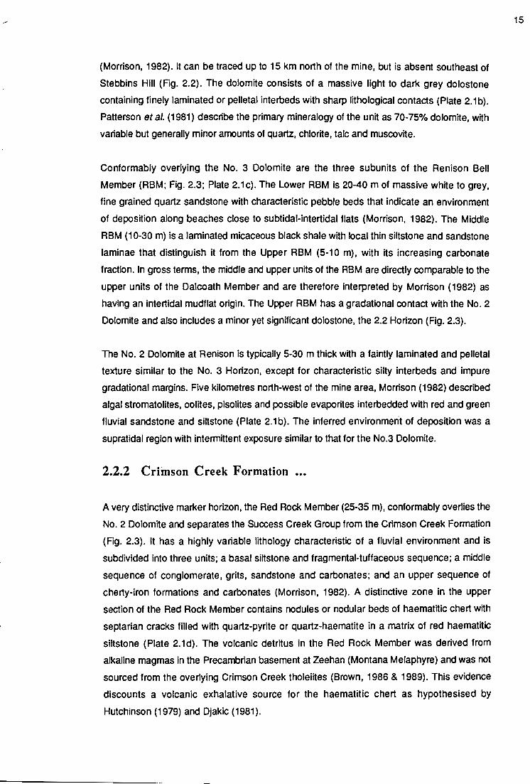
(Morrison, 1982). It can be traced up to 15 km north of the mine, but is absent southeast of
Stebbins Hill (Fig. 2.2). The dolomite consists of a massive light to dark grey dolostone
containing finely laminated or pelletal interbeds with sharp lithological contacts (Plate 2.1 b).
Patterson eta/. (1981) describe the primary mineralogy of the unit as 70-75% dolomite, with
variable but generally minor amounts of quartz, chlorite, talc and muscovite.
Conformably overlying the No. 3 Dolomite are the three subunits of the Renison Bell
Member (RBM; Fig. 2.3; Plate 2.1c). The Lower RBM is 20-40 m of massive white to grey,
fine grained quartz sandstone with characteristic pebble beds that indicate an environment
of deposition along beaches close to subtidal-intertidal flats (Morrison, 1982). The Middle
RBM (1 0-30 m) is a laminated micaceous black shale with local thin siltstone and sandstone
laminae that distinguish it from the Upper RBM (5-10 m), with its increasing carbonate
fraction. In gross terms, the middle and upper units of the RBM are directly comparable to the
upper units of the Dalcoath Member and are therefore interpreted by Morrison (1982) as
having an intertidal mudflat origin. The Upper RBM has a gradational contact with the No.2
Dolomite and also includes a minor yet significant dolostone, the 2.2 Horizon (Fig. 2.3).
The No. 2 Dolomite at Renison is typically 5-30 m thick with a faintly laminated and pelletal
texture similar to the No. 3 Horizon, except for characteristic silty interbeds and impure
gradational margins. Five kilometres north-west of the mine area, Morrison (1982) described
algal stromatolites, oolites, pisolites and possible evaporites interbedded with red and green
fluvial sandstone and siltstone (Plate 2.1 b). The inferred environment of deposition was a
supratidal region with intermittent exposure similar to that for the No.3 Dolomite.
2.2.2 Criinson Creek Formation •••
A very distinctive marker horizon, the Red Rock Member (25-35 m), conformably overlies the
No. 2 Dolomite and separates the Success Creek Group from the Crimson Creek Formation
(Fig. 2.3). It has a highly variable lithology characteristic of a fluvial environment and is
subdivided into three units; a basal siltstone. and fragmental-tuffaceous sequence; a middle
sequence of conglomerate, grits, sandstone and carbonates; and an upper sequence of
cherty-iron formations and carbonates (Morrison, 1982}. A distinctive zone in the upper
section of the Red Rock Member contains nodules or nodular beds of haematitic chert with
septarian cracks filled with quartz-pyrite or quartz-haematite in a matrix of red haematitic
siltstone (Plate 2.1d). The volcanic detritus in the Red Rock Member was derived from
alkaline magmas in the Precambrian basement at Zeehan (Montana Melaphyre) and was not
sourced from the overlying Crimson Creek tholeiites (Brown, 1986 & 1989). This evidence
discounts a volcanic exhalative source for the haematitic chert as hypothesised by
Hutchinson (1979) and Djakic (1981 ).
15

The No. 1 Dolomite (8-25 m) is conformable with the underlying Red Rock and is a chemically
impure equivalent of the No. 2 and No. 3 Dolomites having well developed silt-mudstone
interbeds up to 4 min thickness (Fig. 2.3; Plate 2.1b). The environment of deposition for the
No.1 Dolomite was one of a supratidal mudflat (Morrison, 1982).
The 4000+ m thick Crimson Creek Formation overlies the Renison Mine Sequence and
represents a period of rapid sedimentation together with tholeiitic intrusions on an unstable
sheH margin. Morrison (1993) subdivides the lower 900m of the Crimson Creek Formation
into four main units based on sedimentary cycles with distinct lithological sequences. The
lower subunits are sandstone-dominated; the middle subunits siltstone-dominated; and the
upper subunit calcareous (Plate 2.1e & f). The Dreadnought Hill Member represents the
basal unit of the Crimson Creek Formation in the mine area (Fig. 2.3). Minor evaporitic
horizons, scattered throughout the succession, are interpreted as examples of shallow
water sabkha environments (Kitto, 1990). Gabbroic sills and dykes (?) occur within the
Crimson' Creek Formation at Renison and their geochemistry suggests that these
continental rift tholeiites were cannibalised as a source for Crimson Creek sediments (Plate
2.1g).
2.3 SUMMARY OF TECTONIC AND STRATIGRAPHIC EVENTS
IN THE RENISON DISTRICT •••
The following overview presents the salient features from stratigraphic and tectonic events in
western Tasmania, that have been instrumental in the geological history of the Renison
district. Deposition of the Renison mine sequence occurred locally in rift basins along a
thinned continental margin, controlled by passive rifting of the Proterozoic continental crust
in the Late Precambrian to Early Cambrian. The stratigraphy, sedimentology, texture and
composition of the Cambrian dolostones at Renison suggest they originated in a supratidal
to intertidal environment, possibly as direct precipitates from saturated seawater or in part by
replacement of calcite formed in the subtidal environment (Morrison, 1982). Arc-continental
collision in the Middle Cambrian thrust allochthonous sheets of forearc westward over the
continental margin resulting in the formation of the Serpentine Hill Ultramafic Complex near
Renison. Middle Devonian Tabberabberan deformation produced a north-northwest
trending fold pair in the Renison area (Fig. 2.2) affecting the Serpentine Hill Complex. The
Devonian Pine Hill Granite was emplaced syn- to post- Tabberabberan deformation at the
intersection of the ultramafic suture with the structural anticlinal high in the sediments.
Hydrothermal fluids associated with Sn mineralisation were sourced from the highly
fractionated Sn-rich Pine Hill Granite. The dolostones at Renison provided a chemical trap for
the tin laden mineralising fluids. The following chapter deals in detail with the events in the
Renison area responsible for structural preparation of the host sequences, which allowed
1€

hydrothermal fluids access to the dolomite units and resulted in stratabound carbonate
replacement mineralisation.
17

~ 18
CHAPTER 3: STRUCTURAL GEOLOGY
3.1 INTRODUCTION •••
The regional tectonics of western Tasmania and the stratigraphy of the Renison district
outlined in Chapter 2 provide the basis for a discussion of the structural history of the
Renison area. A review of ductile deformation is followed by a detailed investigation of the
brittle deformation events recognised at Renison, and their control on Sn mineralisation.
Several deformation events have been recognised in the Palaeozoic Dundas Trough of
western Tasmania (Fig. 1.1; eg., Carey, 1953; Blissett, 1962; Solomon, 1962; Williams,
1978; Brown, 1986 & 1989; Collins & Williams, 1986; Berry, 1989; Corbett & Turner, 1989;
Williams et al., 1989). These events have been crucial to the evolution of the Dundas
Trough since Eo-Cambrian times (Crawford and Berry, 1992) and are integral in controlling
sites of mineralisation.
In the Middle Devonian, the Tabberabberan Orogeny produced regional north-northwest
fold trends in the central Dundas Trough (Zeehan/Gormanston Trend) with steep reverse
faults and later wrench reactivations (Berry, 1989). A Late Devonian thrusting event in the
Zeehan area added further complexity (Findlay & Brown, 1992; Everard eta/., 1992).
At Renison, structural investigations have been undertaken by Patterson (1979), Patterson
eta/. (1981), Komyshan (1984), Davies (1985), Brown (1986), Holyland (1987), Marjoribanks
(1989 & 1990), Kitto (1990 & 1992a), Kitto and Berry (1991 & 1992), and Lea (1991). These
researchers recognised an early north-northwest ductile deformation related to the
Zeehan/Gormanston fold trend which was overprinted by later brittle deformation.
3.2 PRE-TABBERABBERAN DEFORMATION •••
The earliest structural event at Renison is associated with Cambrian syn-sedimentary
deformation within the Dalcoath Contorted and Upper Contorted units (Morrison, 1982).
These units contain highly irregular axial orientations and non-cylindrical fold hinges,
consistent with soft-sediment deformation (Davies, 1985; Holyland, 1987). Holyland (1987)
noted minor metre-scale, overturned, and recumbent intrafolial rheomorphic folds in the
Dalcoath Member adjacent to the Federal-Bassett Fault in the Penzance Orebody (see

Chapter 5; Fig. 5.10), but considered that similar intrafolial folds in the Renison Bell Member
were tectonic because of their consistent axia! orientations and fold hinges. Davies ( 1985)
and Holyland (1987) consider that no evidence exists to support syn-sedimentary growth
faults at Renison, and therefore deformation of the sediments must be related to Early
Cambro-Ordovician (Corbett and Lees, 1987) or Devonian Tabberabberan events.
3.3 TABBERABBERAN DEFORMATION •••
3.3.1 Regional Devonian Dl Deformation •••
In the Dundas Trough (Fig. 1.1 ), fold geometry was strongly influenced by the competent
behaviour of the bounding Proterozoic metasedimentary massifs. The first phase of Middle
Devonian Tabberabberan deformation in western Tasmania consisted of large-scale, upright
and tight folds with northerly trends and half wave lengths up to 15 km (Williams eta/., 1989).
3.3.2 Devonian Dl Deformation At Renison •••
The Crimson Creek Formation and the underlying Success Creek Group, at Renison, have
been folded with northerly trends similar to the West Coast RangeNalentines Peak Trend
(Brown, 1986; Holyland , 1987). This deformation event tilted the Success Creek Group
sequence to the east and produced a basal dedetachment surface on the contact with the
underlying Oonah Formation in the Pieman River west of Renison (Brown, 1986). Holyland
(1987) demonstrated that the degree of tilting of the Success Creek Group was not uniform,
but was defined by three zones that represent a west facing asymmetric fold, 2 km west of
the mine.
3.3.3 Regional Devonian D2 Deformation .••
During the second stage of Middle Devonian peformation in western Tasmania the Tyennan
massif acted as two rigid bodies and deformation of the central Dundas Trough sediments
produced a northwest trending corridor of folds called the Zeehan/ Gormanston trend
(Williams eta/., 1989). Near Zeehan the largest amplitude folds have steeply dipping axial
surface cleavages and a half-wavelength of approximately 4.5 km. Smaller folds with half
wavelengths of 1 km or less are present locally (Blissett & Gulline, 1962; Blissett, 1962;
Solomon, 1962; Corbett & Lees, 1987). Immediately east of the mine area, the 17 km long
and 7 km wide, northwest trending, Huskisson Syncline formed as part of the
Zeehan/Gormanston fold trend, which modified the earlier West CoastNalentines Peak
syncline (Brown, 1986; Williams eta/., 1989).
19

-"'
Devonian D2 deformation formed in a northeast-southwest oriented compressive stress
field that resulted in moderately tight to open northwest-southeast trending folds and north
to northwest trending axial plane cleavages. Deformation occurred in elongated basins, and
portions of domes. As a consequence, the end of fold structures plunge up to 40° (Williams
et at., 1989).
Devonian granitoids were emplaced during and after Devonian D2 deformation (Berry,
1992). Intrusions occurred at the intersection of Devonian D2 anticlinal highs and sutures
related to Cambrian mafic/ultramafic complexes. Emplacement initiated brittle deformation
features and provided a major focus for hydrothermal fluids that resulted in subsequent Sn
and base metal mineralisation (Leaman, 1988; Marjoribanks, 1989).
3.3.4 Devonian D2 Deformation At Renison •••
At Renison, the Eo-Cambrian sedimentary rocks have been affected by a large-scale
northwest trending fold, the Renison Bell Anticline (Blissett, 1962; Collins, 1972; Patterson,
1979; Patterson eta/., 1981; Manly, 1982; Davies, 1985; Brown, 1986 & 1989; Holyland,
1987). The lack of cleavage development has prevented an accurate assessment of the
location for the hinge zone. Based on structural investigations by Holyland (1987) the
anticlinal axis is considered to occur immediately west of the Renison Bell township (Fig.
2.2). The fold axis is defined by a northwest trending, 800m wide area of shallow dips (10°-
20°) with a southerly plunge. The rounded, upright nature of the anticline is indicated by
symmetrical progressive steepening of the fold limbs to 50° - 70°. Holyland (1987)
recognised a number of parasitic folds with 1 00 - 300m wavelengths in the mine area . These
structures were interpreted from first order residual surfaces to the footwall of the No. 2 and
No. 3 Dolomite horizons from drill hole intersections. The existence of these parasitic folds is
debatable as the folds coincide with horst and graben structures recognised in this study
(Section 3.5.3.3).
At Pine Hill, 2.5 km south of the mine area (Fig. 2.2), the Cambrian Serpentine Hill Ultramafic
Complex represents an allochthonous thrust sheet that overlies the Crimson Creek
Formation (Berry & Crawford, 1988). Devonian D2 folding associated with the Renison Bell
Anticline has produced a concave northwest arcuate contact with the underlying Crimson
Creek Formation. Komyshan (1984) and Holyland (1987) described a major northwest
trending, southerly plunging, upright symmetrical syncline one kilometre west of the
Renison Bell anticline that has produced a convex northwest arcuate contact between the
Serpentine Hill Ultramafic complex, and the Crimson Creek Formation. The sigmoidal
appearance of the Serpentine Hill Ultramafic Complex therefore results from Devonian D2
folding interference with the allochthonous contact between the Serpentine Hill Ultramafics
20
and the underlying Crimson Creek Formation, in contrast to the left lateral shearing event
proposed by Marjoribanks (1989). Suggestions that the northeast striking Heazlewood River
Ultramafic Complex are the strike slip equivalents of the Serpentine Hill Ultramafic Complex
appear therefore to be erroneous.
3.3.5 Regional Devonian D3 Deformation •..
Regional D3 deformation occurs as axial, transverse normal, and wrench faults within the
Zeehan area, along flexure points and culminations in Devonian F2 hinge zones (Blissett,
1962). Initial movement probably took place during Devonian granite emplacement, but
post-Permian faulting typically masks the significance of such structures (Williams eta/.,
1989). In Tasmania, field evidence indicates that emplacement of Devonian granitoids
occurred by largely passive intrusion mechanisms rather than by forceful means (Gee &
Groves, 1971). Foliations on the margins of plutons in northeastern Tasmania indicate flow
mechanisms during emplacement of the granitoids rather than forceful stoping of the
country rock (Kitto, 1982; McClenaghan & Williams, 1983; McClenaghan, 1985).
Berry (1989) produced the first detailed analysis of the history of brittle deformation using
kinematic indicators in western Tasmania. In the Henty Fault Zone, northeast of Rosebery
(Fig 2.1 ), high angle reverse faults initiated during Devonian granite emplacement were
overprinted by Late Devonian sinistral reactivations and minor post-Devonian movements.
Devonian Ag - Pb - Zn, and Au-bearing veins are associated with these structures (Bamford
& Green, 1986).
Mid Devonian - Early Carboniferous mineral deposits of Tasmania are spatially and genetically
associated with granitoid emplacement (Collins et a/., 1989). Economically important tin
tungsten skarn and carbonate replacement deposits occur in western Tasmania (e.g.
Renison, Mt. Bischoff, Cleveland, Kara, King Island) associated with Late Proterozoic and
Early Palaeozoic carbonates. Several exogranitic tin (-tungsten) deposits are clearly zoned,
with outer halos of argentiferous galena and sphalerite (e.g., Zeehan, Moina and Scamander
districts; Waller, 1904; Twelvetrees & Ward, 1910; Parks, 1955; Blissett, 1962; Both &
Williams, 1968a & b; Both eta/., 1969; Jennings, 1979; Solomon, 1981; Ruxton & Plummer,
1984; Anderson, 1986). The current study has recognised the existence of another large
zoned mineral field in the Renison-Dundas district that is spatially associated with the
emplacement of the Pine Hill Granite.
3.3.6 Devonian D3 Deformation At Renison ••.
At Pine Hill, the emplacement of the Mid - Devonian Pine Hill Granite (355±4 Ma; Brooks,
1966) was controlled by the intersection of the Renison Bell Anticlinal high and the
21

...,;
Serpentine Hill Ultramafic Complex (Fig. 2.2). The following section outlines the history of
brittle deformation at the Renison Tin Mine, and links Devonian D3 deformation features with
the emplacement of the Pine Hill Granite. Subsequent sections outlines the structural
geology of the Renison mine and illustrate the importance of structural preparation of host
sequences for the formation of world class carbonate replacement orebodies. Brittle
deformation and reactivation events at Renison have previously been documented in Kitto
(1990), and Kitto and Berry (1991).
3.4 BRffiLE DEFORMATION AND REACTIVATION AT RENISON •••
3.4.1 Introduction •.•
It has long been recognised that the mid-Palaeozoic mineral deposits in Tasmania, are
spatially and genetically associated with emplacement of Middle Devonian - Early
Carboniferous granitoids. What has not been recognised, or demonstrated previously, is
the intimate association between granitoid emplacement, brittle deformation of the host
sequences and the focusing of ascending hydrothermal fluids. The aim of this investigation
is to determine the history of brittle deformation and fault reactivation at Renison via a
detailect study of fault striations to better assess the mechanisms necessary for the formation
of the carbonate replacement mineralisation.
The Renison ore deposit occurs on the north-east limb of a broad south-east plunging
anticline (Renison Bell Anticline), which constitutes a horst block bounded to the north-east
by the Federal-Bassett Fault, and to the south-west by the poorly defined Argent Fault (Fig.
2.2; Section 3.5.1, Fig. 3.9).
The major fault sets within the Renison Mine are :
(i) Federal-Bassett Fault,
(ii) Transverse Faults (Mercury Fault, 'Shear L', 'Shear P', 'Shear R', 'ShearS') and
(iii) Blow Fault Complex (e.g., Blow Fault, Lead Lode Fault and Black Face Fault).
NOTE: At Renison the term 'shear' is a historical term and does not have a generic
connotation. The 'shears' are collectively referred to as the Transverse Faults (Patterson,
1979).
The Federal-Bassett structure is considered by Holyland (1987) and Marjoribanks (1990) to
represent a failed pre-Devonian monoclinal fold. Folding, however, must have been related
to Devonian F2 events (Section 3.3.3 & 3.3.4), associated with the northwest oriented
Zeehan/Gormanston Trend. Evidence for high ductile strain on the steep north-east limb of
the monocline is recognised in underground workings, and this caused thinning and
2'

.--
boudinage of the mine sequence prior to, or coeval with Late Middle Devonian brittle faulting
(Holyland, 1987; McQuitty, 1991).
3.4.2 Method •••
Investigation of brittle structures at Renison concentrated on fault striations exposed on
underground mine surfaces (Plate 3.1 ). The sense of displacement on fault planes was
determined using the criteria of Petit (1987) and Berry (1989; Fig. 3.1). The criterion most
widely observed were the precipitation of quartz or carbonate minerals on the lee side of a
ledge (Fig. 3.1 a). The next most common displacement sense indicators were striations on
the upstream face of an irregularly corrugated fault plane, or deepening grooves associated
with asperites (Fig. 3.1 b, c). Few examples of microfault textures (e.g., lunate fractures,
striated Riedel fractures) were observed on exposed fault surfaces (Fig. 3.1 d). The relative
ages of striations were determined using overprinting criteria, such as fibre veins from an
earlier deformation being truncated by grooves of a different orientation, or fibre veins found
attached to one side of an undulate surface (Fig. 3.1 e, f). Stress tensors were modelled by
analysing fault striations using a computer program written by Etchecopar eta/. (1981 ).
3.4.3 Fault Striations ..•
Four generations of fault striations have been identified at Renison based on style and
relative ages. First generation fibres occur parallel to steeply plunging undulating fault
surfaces (see Chapter 5, Plate 5.2a). In most cases, early fibres have a mineralogy consistent
with the host vein suggesting contemporaneous mineralisation. Calcite fibre veins or pyritic
polished surfaces dominate fault surfaces not associated with extensive sulfide
mineralisation. Second, and subsequent generations of striations have either calcite or
quartz fibre veins, or pyritic polished surfaces. Overprinting relationships of striations allow
an interpretation of fault histories. No striations predating the mineralising fluids were
observed.
3.4.4 Normal-Dextral Faulting ..•
3.4.4.1 Striation Analysis ..•
Earliest brittle deformation at Renison produced normal-dextral orientations of striations,
grooves and undulations on veins and fault surfaces. All major fault structures exhibit these
deformations, but the most pronounced development occurs along the Federal-Bassett
Fault (Fig. 3.2). Modelled stress tensors for the Federal-Bassett Fault predict a near vertical
maximum compressive stress, cr1. associated with normal faulting. The stress ratio [R = (cr2-
cr3)/(cr1 - cr3) = 0.60] confirms cr2 and cr3 positions, with the near horizontal minimum
23
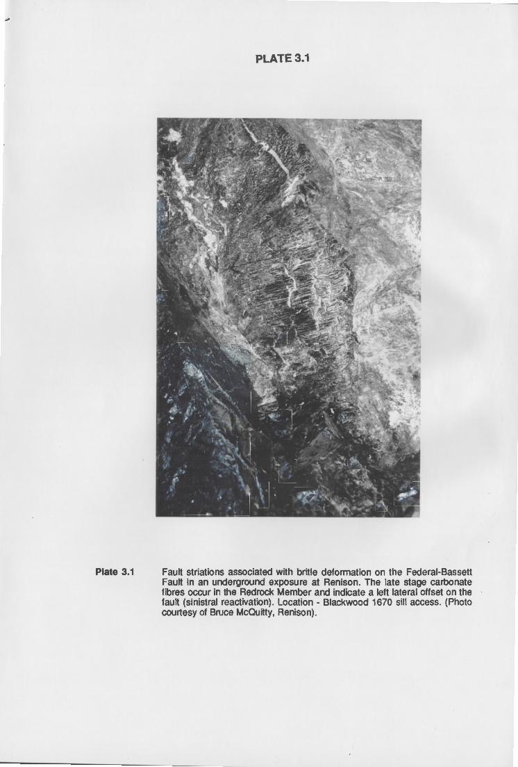
....
Plate 3.1
PLATE 3.1
Fault striations associated with britle deformation on the Federal-Bassett Fault in an underground exposure at Renison. The late stage carbonate fibres occur in the Redrock Member and indicate a left lateral offset on the fault (sinistral reactivation). Location - Blackwood 1670 sill access. (Photo courtesy of Bruce McQuitty, Renison).

.....
Sense of Displacement Criteria
....__ -- ~ ~
A L-----__., 8.....__ ____ __;,-
fibre veins striations
~ ~
c( ·;~ grooves lunate fractures and Riedel shears
....___ ~ ....___
_.,....-
F I
relative age relative age
Figure 3.1 Criteria used to determine sense of displacement (A- D), and relative age (E. F) from fault striations. In all diagrams the missing fault block has moved in a right lateral sense relative to remaining block. A: New minerals crystallised in the lee of a ledge on the fault plane. B: Striations on the upstream face of an irregular surface. C: Grooves deepening to the right because of asperites on the opposing face. 0: Lunate fractures and striated Riedel shears. E: Truncations of grooves, intervening ridges and fibre veins by a later set of grooves indicating relative age. F: Broad ridges parallel to early striations overprinted by later striations on one side only, or having later fibre veins attached to one side indicating relative age.
(From Berry, 1989).
25

FEDERAL-BASSETT FAULT MISCELLANEOUS FAULTS
'SHEAR P' 'SHEARL'
BLOW FAULT PB-LODE FAULT
Figure 3.2 Lower hemisphere equal area projections of fault striations on fault planes compatible with normal-dextral movement on the Federal-Bassett Fault.
26

...-
compressive stress, cr3, trending 84° (Fig. 3.3; Table 3.1 ). Computed stress tensors for
normal-dextral movements on miscellaneous faults at Renison also confirm a near vertical cr1,
and a near horizontal cr3, trending 238° (Fig. 3.3; Table 3.1 ). The normal-dextral stress
models for both the Federal-Bassett Fault and the miscellaneous faults satisfy 95% and 90%
of each data set respectively.
3.4.4.2 Significance
At Renison, the stress field responsible for normal-dextral brittle deformation was unique.
This stress regime has not been recognised previously and does not comply with the
regional Devonian Tabberabberan stress field. Normal-dextral displacement on the Federal
Bassett Fault, and other faults, post-dates the Devonian D2 deformation responsible for the
Renison Bell Anticline. The observation that granite derived Devonian Sn mineralisation was
coeval with fault initiation suggests a genetic association between granite emplacement,
fault initiation and Sn mineralisation at Renison. Aspects of the Renison geology that
support this interpretation are:
(i) Diamond drilling and geophysical surveys (Leaman, 1990) show that a northwest
trending granite ridge outcrops at Pine Hill and plunges shallowly under the mine
workings.
(ii) The orientation of quartz-porphyry dykes and the 350° vein sets of Davies (1985)
and Holyland ( 1987) lie in a plane normal to the minimum compressive stress, cr3,
associated with normal-dextral faulting at Renison.
(iii) The sigmoidal jog observed on the Federal-Bassett Fault, between 'Shear P' and
'Shear L', has a trend and plunge parallel to the normal-dextral motion on the fault
plane that occurred in response to the maximum compressive stress, cr1, plunging
70° to 202°.
(iv) An apophysis in the granite ridge occurs immediately beneath the mine area and is
associated with intense tourmaline alteration.
(v) A domal culmination is recognised in the mine sequence, at Renison, above the
apophysis in the granite.
(vi) The steep northeasterly dipping limb of the Renison Bell Anticline has been a zone
of weakness where brittle (-ductile) deformation features developed.
Up to 700 m of dip-slip displacement occurred on the Federal-Bassett Fault during normal
dextral faulting in the immediate mine area, whereas less than 400 m occurred to the north of
the mine (Marjoribanks, 1990; Lea, 1991). The amount of displacement on the Federal
Bassett Fault south of the mine area is unknown, but is considered to decrease away from
the mine area.
27

Table 3.1 Principal stress directions calculated from fault striations.
O't 0'2 O'J Plunge Trend Plunge Trend Plunge Trend Error Data No.
Deformation (0) (0) (0) (0) (0) (0) R (0) Fitted Tota1
Normal-dextral FBF 70±31 202 ±50 17± 22 351 ± 16 10 ± 28 84 ±9 0.60±053 8 11 13 Mise 81 ± 15 129 ± 89 9± 13 328 ±44 3±13 238 ± 45 0.15 ± 0.13 11 15 17
Dextral wrench FBF 12± 10 172±45 29±120 269±73 58±109 61 ± 146 020±0.46 10 10 11 Mise 20±29 181 ± 17 68 ± 25 335±45 9±8 87±15 0.61 ±0.32 12 5 7
Reverse-sinistral FBF 7±13 88±2 10±6 179±4 78± 12 325 ± 41 0.57 ± 0.25 7 9 11 Mise 3±13 73±20 6±14 163 ± 23 83 ± 17 320 ± 66 0.51 ± 029 16 10 12
Normal-sinistral FBF Insufficient data to analyse Mise 80±6 66±45 10±6 248± 11 0±7 158 ± 11 0.37 ± 0.30 17 11 13
Table 3.2 Present-day stress magnitudes and orientations (Golder & Assoc. 1981).
Principal Compressive Orientation Magnitude (MPa)
Statistical Parameter Stress (0
)
Maximum (O't) 126-08
Intermediate (0'2) 357-75
Minimum (0'3) 218- 12
FEDERAL-BASSETT FAULT
232- 0.102 R.L
122 - 0.054 R.L
77-0.034 RL
r2 = 0.73
r2 = 0.82
r2 = 0.63
MISCELLANEOUS FAULTS
Figure 3.3 Lower hemisphere equal area projections of calculated principal compressive stress directions for fault striations on fault planes compatible with normal-dextral movement on the Federal-Bassett Fault.
2c.

In summary, dip-slip deformation features are the resultant of forceful granitic emplacement
by the Devonian Pine Hill Granite. Granite emplacement initiated the Federal-Bassett Fault
on the eastern limb of the Renison Bell Anticline, with a minor component of ductile
deformation. Solomon and Groves (1994) suggest that expansion of the pluton after
emplacement, due to fluid exsolution, initiated or reactivated the Federal-Bassett Fault.
Taylor and Pollard (1985) consider that progressive fracture development (reactivations)
above the apical zone of a pluton provide the mechanisms for tapping the pore space fluids
within the pluton, and that such mechanisms control the spatial and temporal vein
assemblages. The evidence outlined above, linking granite emplacement, brittle
deformation and mineralisation supports such an interpretation, but suggests that these
events are essentially coeval.
Granitic doming beneath the mine area, associated with the granite apophysis, provided the
mechanism to initiate other major fault sets, in addition to the Federal-Bassett Fault. The
normal-dextral stress tensors computed for the Federal-Bassett Fault are also consistent
with early brittle deformation on the sub-parallel Blow Fault Complex, west of the Federal
Bassett Fault (Fig. 3.2). The Blow Fault represents the western limit of carbonate
replacement mineralisation at Renison. Marjoribanks (1990) considered the Blow Fault
Complex to be a brittle deformation structure related to the Pine Hill intrusion, but with a
dextral strike-slip origin. Overprinting relationships of fault striations, however, indicate that
normal-dextral brittle deformation preceded any dextral strike slip movement on these fault
surfaces.
Figure 3.4 illustrates the structural relationships expected in a right lateral simple shear
environment. This figure is shown in the cr1 - cr3 plane for normal-dextral faults at Renison.
Riedel shear terminology is modified from Tchalenko and Ambraseys (1970) and Bartlett et
a/. (1981). Extension fractures (i.e., the 350° vein sets or the quartz porphyry dykes) form
when the effective stresses are tensile in response to simple shear at approximately 45° to
the master fault (Biddle & Christie-Slick, 1985).
The Transverse Faults (e.g., 'Shear P' & 'Shear L'), occur as dip-slip brittle deformation
structures between the Federal-Bassett and the Blow Faults, and formed synchronously
with the two bounding structures. When normal-dextral fault data for the Federal-Bassett
Fault are rotated on a stereographic projection into a pure wrench system (Fig. 3.5), it can be
seen that 'Shear P' may have been initiated as a secondary reverse fault relative to the
Federal-Bassett Fault. This implies extension occurred in the intermediate compressive
stress direction, cr2. in response to arching of the mine sequence over the granite
apophysis beneath the mine, in a north-south direction. This interpretation is supported by
cross-section wireframe modelling, which shows a domal flexure in the mine sequence
29

....
O'J <;:::,
11 b'
b IJ
/ '~lilts
~ O'J
Figure 3.4 Orientation of folds, thrusts, normal faults, Riedal (R) shears, secondary Riedal (R') shears and pressure (P) shears as determined from experimental modelling (adapted from Tchalenko & Ambraseys, 1970; Harding, 1974; Bartlett et al., 1981; Sylvester, 1988).
NORMAL -DEXTRAL MOTiON
ROT AT ION TO DEXTRAL -'HRE~lCH
Figure 3.5 Lower hemisphere equal area projection of the Federal-Bassett Fault (FBF) and the secondary reverse structures, 'Shear P' and Polaris. Fault striation data with normal-dex1ral movement on the Federal-Bassett Fault has been rotated into a pure wrench system, and subsequent rotation of 'Shear P' and Polaris striation data places both structures into secondary reverse fault positions relative to the Federal-Bassett Fault (see Fig. 3.4).
30

above the apophysis in the granite, and normal faulting associated with 'Shear P~. A similar
origin is invoked for the formation of the other Transverse Faults.
Polaris, a carbonate-magnetite orebody at Renison, occupies a shallow northeast dipping
shear zone at a location where 'Shear P' and 'Shear L' have merged to form one structure
close to their intersection with the Blow Fault Complex (Appendix I, Sections 66380N to
66560N; Section 3.5, Figs. 3.11 & 3.16). Figure 3.5(b) illustrates that the origin for the
structure hosting the Polaris orebody was the same as 'Shear P'.
3.4.5 Dextral Wrench Movement .••
3.4.5.1 Striation Analysis .••
Dextral wrench reactivations overprint the initial normal-dextral movement on the Federal
Bassett Fault and associated structures (Fig. 3.6; 'Shear L', Blow Fault, Miscellaneous
Faults). Quartz or calcite fibres on mineralised veins, or pyritic polished surfaces on
unmineralised fault planes, are the dominant brittle deformation features. Overprinting
criteria for the dextral wrench striations include fibre veins attached to one side of an
undulating surface or striations on the upstream face of an undulating fault plane (Fig. 3.1 ).
Ninety-five percent of the dextral wrench data set for the Federal-Bassett Fault (Table 3.1)
produced an exact solution for a near horizontal maximum compressive stress, cr,, trending
172° (Fig. 3.6). A low stress ratio (R = 0.20, Table 3.1 ), however, implies that the
intermediate compressive stress, cr2, and the minimum compressive stress, <J3, are similar in
their compressive strengths and are therefore not well constrained. A stress analysis for
80% of the dextral wrench data on the Miscellaneous Faults indicates a near horizontal cr,, trending 181° (Fig. 3.6). The stress ratio (R = 0.61, Table 3.1) demonstrates that the near
vertical cr2. and the horizontal <J3, are well constrained for these faults. Regionally cr2 is also
vertical (Berry, 1989).
3.4.5.2 Significance .••
Striations attributed to regional Devonian dextral wrench reactivations occur on all major and
minor fault surfaces at Renison. This reactivation of fault surfaces occurred as the local stress
field associated with granite emplacement and fault initiation began to decay and the
regional Devonian Tabberabberan stress field began to dominate.
A dilational jog on the Federal-Bassett Fault hosts the Federal Orebody between
intersections with 'Shear P' and 'Shear L' (Fig. 2.2), demonstrating that dextral wrench
31
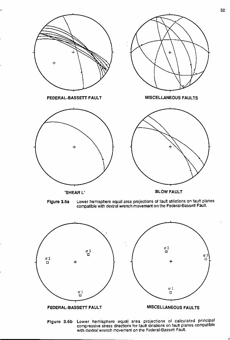
---
FEDERAL-BASSETT FAULT MISCELLANEOUS FAULTS
'SHEAR L' BLOW FAULT
Figure 3.6a Lower hemisphere equal area projections of fault striations on fault planes compatible with dextral wrench movement on the Federal-Bassett Fault.
FEDERAL-BASSETT FAULT MISCELLANEOUS FAULTS
Figure 3.6b Lower hemisphere equal area projections of calculated principal compressive stress directions for fault striations on fault planes compatible with dextral wrench movement on the Federal-Bassett Fault.
32
,..;

displacement and mineralisation were contemporaneous. A minor component of localised
ductile deformation was associated with wrench movement. Holyland (1987) has used trend
surface residuals for the footwall and hanging wall of the Federal-Bassett Fault to indicate
that oblique normal dextral slip movement on the fault was 3 m ± 1 m, plunging approximately
15° south. Holyland's (op. cit.) directional estimates agrees well with the principal
compressive stress directions calculated in this investigation (<Jt plunging 12° at 172°).
Dextral wrench reactivations produced a component of ductile deformation in the form of an
open dextral kink fold with an east-west trending axes upon the mine horst (Fig. 2.2). This
event affected the Federal-Bassett and the Blow Faults, near their intersections with 'Shear
P' and 'Shear L'. Folding accentuated the dilational component of the Federal Orebody, and
the weak en-echelon nature of the Transverse Faults, due to differential movements along
these structures. Marjoribanks (1989) noted that the dextral kink fold affected a domain of
steeply dipping mine sequence rocks adjacent to the Federal-Bassett Fault. In plan outline,
the Federal and adjacent North Stebbins Orebodies below 1980 R.L. (see Chapter 5, Fig.
5.1 0) highlight folds which plunge steeply down dip, parallel to the normal-dextral movement
that initiated the fault structures.
The dextral wrench on the Federal-Bassett Fault facilitated continued brittle extensional
opening of veins normal to the minimum compressive stress, a3. Steeply dipping, north
northwest trending quartz-sulphide filled structures are recognised in the fracture controlled
Melba Orebody that occurs within the competent Renison Bell Member between 'Shear P'
and 'Shear L', adjacent to the Federal-Bassett Fault (see Fig. 5.9 & Plate 5.1b; Davies, 1985;
Holyland, 1987).
The Blow Fault has a more definite set of dextral wrench striations on fault surfaces than the
earlier normal-dextral striations associated with fault development (Plates 3.2a, b). This
suggests a larger offset occurred on the Blow Fault during dextral wrench reactivation.
Cross-section reconstructions, however, show that right-lateral displacement on this
structure was insufficient to offset the Argent Fault which bounds the mine horst south of
Renison (Appendix I, Sections 65680N to 65800N). The Blow Fault joins the Federal
Bassett Fault north of the mine area, as it changes strike from west-northwest to northwest
(Fig. 2.2). A transfer of strain from the Federal-Bassett Fault to the Blow Fault, associated
with dextral wrench reactivation, occurred at this point and produced the weak dextral kink
fold on the mine horst (Fig. 2.2).
33

Plate 3.2a
Plate 3.2b
Looking southeast along strike of the steep northeast dipping Blow Fault where it cuts the Murchison Highway in the Black Face Opencut. A number of old workings are aligned along the hangingwall of this structure. (See Appendix I- section 66500N for a geological interpretation).
Looking west at the footwall of the Blow Fault in the railway cutting adjacent to the Murchison Highway, and showing grooves and corrugations associated with dextral wrench movement.
-o r ~ m w N

~
~
.;
.;
3.4.6 Reverse-Sinistral Movement
3.4.6.1 Striation Analysis ...
A third set of striations with a reverse-sinistral sense of displacement overprint earlier fauH
striations throughout Renison. Calcite fibre veins and/or deepening grooves associated wHh
asperHes represent the dominant kinematic criteria. The relative ages of overprinting were
obtained using striations on upstream faces of undulating fauH planes or grooves truncating
fibre veins of an earlier event. A stress solution, modelled for 90% of the reverse-sinistral
data for the Federal-Bassett Fault, computed a stress ratio (R = 0.57, Table 3.1) that
confirmed a near horizontal value for the maximum compressive stress, cr,, trending 88° and
a minimum compressive stress, cr3, that was almost vertical (Fig. 3.7). A similar solution was
obtained for the miscellaneous fauH data (Fig. 3.7, Table 3.1 ).
3.4.6.2 Significance .••
Post-Devonian (?) reverse-sinistral movement at Renison due to east-west compression has
not been reported previously. The origin of this reactivation event is possibly related to:
(i) a reverse-sinistral rebound of the host sequence at Renison after normal-dextral
faulting on the limbs of the Renison Bell Anticline, due to forceful granite
emplacement; or
(ii) a localised response to the southeasterly directed, Late Devonian, Tenth Legion
Thrust recognised in the Zeehan area by Everard et at. (1992), and Findlay and
Brown (1992).
The absence of mineralisation during reverse-sinistral reactivation indicates that
hydrothermal fluid circulation had ceased, consistent wHh a late-syn to post Tabberabberan
age of deformation. Displacements during reverse-sinistral reactivations were no more than a
few metres .
3.4.7 Normal-Sinistral Movement •••
3.4. 7.1 Striation Analysis ...
The final brittle deformation identified on most fault planes at Renison was a normal-sinistral
reactivation. The kinematic crHeria are similar in style to earlier reverse-sinistral crHeria, having
either calcite fibre veins, or deepening grooves associated with asperites. Weakly
developed normal-sinistral striations truncate earlier fibre veins. Stress analysis of normal
sinistral displacements on miscellaneous faults provided a stress solution for 90% of the
35

---
~
~
/
'
.-'"'
---
FEDERAL-BASSETT FAULT MISCELLANEOUS FAULTS
+
'SHEARL' PB-LODE FAULT
Figure 3.7a Lower hemisphere equal area projection of fault striations on tau~ planes compatible w~h reverse-sinistral movement on the Federal-Bassett Fau~.
cr3
* +
FEDERAL-BASSETT FAULT
"~
MISCELLANEOUS FAULTS
Figure 3.7b Lower hemisphere equal area projection of calculated principal compressive stress directions for tau~ striations on fault planes compatible with reverse· sinistral movement on the Federal-Bassett Fau~.
3C

i
~
/
data; insufficient data was collected from the Federal-Bassett Fault for analysis. The
maximum compressive stress, cr1, was almost vertical and the minimum compressive stress,
0"3, was horizontal, trending 158° (Fig. 3.8, Table 3.1). A low stress ratio (R = 0.37) for the
miscellaneous fauHs implies that cr2 and 0"3 may have been interchangeable.
3.4. 7.2 Significance ...
Normal faulting is recognised in the Ea~y to Middle Tertiary of Tasmania, due to extension in
a northeast direction (Berry and Banks, 1985; Berry ,1989 ). Renison lies very close to the
eastern margin of the Henly Surface, a large peneplain dissected by Tertiary fauHing. This
Tertiary event may well have caused the reactivation represented as normal-sinistral
movement on pre-existing fauH surfaces at Renison. The maximum displacement along
these fauHs is less than two or three metres.
3.4.8 Present-day Stresses •••
The present-day in-situ stresses for the Renison area were determined using an overcoring
strain relief procedure (Golder & Assoc., 1981 ). The magn~ude and orientation of these
stresses are shown in Table 3.2. The intermediate compressive stress, cr2, is near vertical
and the maximum compressive stress, O"J, is near horizontal trending 126°. The orientation
of the present day principal compressive stresses match those usually associated with
wrench tectonics. No evidence was found for reactivation of fauH surfaces under this stress
regime at Renison.
3.4.9 Summary Of Brittle Deformation And Reactivation ...
A detailed study of kinematic indicators on the mineralised fauHs at Renison determined the
stress field during mineralisation. Four phases of brittle deformation (Devonian to Tertiary)
were determined based on style and relative ages of fault striations.
First generation fibre growths have a mineralogy consistent w~h the host veins, suggesting
contemporaneous mineralisation. Subsequent generations of striations are dominated by
calc~e or quartz fibre veins, and striated pyritic polished surfaces occur on fauH planes where
fibre veins are absent. No striations pre-dating mineralisation have been recognised. ln~ial
normal-dextral brittle deformation at Renison formed under a near vertical maximum
compressive stress, 0"1, and near horizontal minimum compressive stress, 0"3, trending 84°.
In western Tasmania this stress regime is unique to Reniscin, and initiated the Federal
Bassett Fault along a developing eastern monoclinal margin of the northwest trending
3~

.. .-. I
FEDERAL-BASSETT FAULT MISCELLANEOUS FAULTS
'SHEAR P' BLOW FAULT
Figure 3.8a Lower hemisphere equal area projections of tau~ striations on fault planes compatible wtth normal-sinistral movement on the Federal-Bassett Fault.
ao x
Cll +X
MISCELLANEOUS FAULTS
Figure 3.8b Lower hemisphere equal area projection of calculated principal compressive stress directions for tau~ striations on tau~ planes compatible with normalsinistral movement on the Federal Bassett Fault.
38

Renison Bell Anticline. ln~ial movements on the Blow Fault Complex and Transverse Faults
also occurred during the normal-dextral event. Displacement of up to 700m occurred on the
Federal-Bassett Fault during normal-dextral faulting, and the early stages of mineralisation
were coeval to this event. A regional Devonian dextral wrench event reactivated the earlier
faults in response to a near-horizontal O"t trending 172°, and a near-vertical cr2. Dextral
wrench movement of up to 5 m opened a dilational jog on the Federal-Bassett FauH in which
later stages of the Federal Orebody form. The dilational jog was enhanced by development
of an E-W open dextral kink fold across the mine horst. Post-Devonian reverse-sinistral
displacements of less than a few metres overprinted the earlier fauH striations. The stress
tensors for this event indicate that O"t was near horizontal (088°), and 0"3 vertical. The
reverse-sinistral event has not been previously reported. Minor Tertiary normal-sinistral
reactivation is the last recognised brittle deformation event at Renison and occurred w~h a
near vertical O"t, and horizontal 0"3 trending 158°.
Syn-Devonian normal fauHing at Renison contrasts with compressional structures related to
the Taberraberran Orogeny throughout western Tasmania. The horst structure is interpreted
to result from modHication of a developing monoclinal fold on the eastern limb of the
Devonian Renison Bell Anticline by forceful emplacement of the Pine Hill Granite. The radial
stress field added to the regional stress field (reflected by dextral wrenching after granite
emplacement) and caused the interchange of the 0"1 and 0"2 directions. This interchange
initiated the normal fault movement on the Federal-Bassett Fault along a monocline
immediately above the gran~e. The local uplift led to north-south stretching of the uplifted
block, producing the extensional Transverse Faults. The zone of largest uplift on the
Federal-Bassett FauH was dilational, providing the major focus for mineralising fluids. Fluids
were also focused along the extensional low-angle Transverse FauHs. During the later part of
the mineralising event, the granite-related stress field decayed and movement on the
Federal-Bassett Fault reverted to a dextral wrench movement consistent with the regional
pattern. Mineralisation had ceased prior to minor post-Devonian reactivations associated wtth
reverse-sinistral and normal-sinistral brittle deformations.
3.5 STRUCTURAL CONTROLS TO MINERALISATION ...
3.5.1 Introduction ...
Preliminary interpretations of structural controls on mineralisation at Renison have previously
been documented by Kitto (1992a), and Kitto and Berry (1992).
At Renison, Lea (1991) correlated a number of the regional fauH structures w~h a tensional
regime associated with emplacement of the steep sided northwest-southeast trending Pine
39

Hill Granite ridge (Fig. 3.9). The Federal-Bassett Fau~ was inferred to project steeply upward
from the northeast margin of the gran He ridge into the overlying Success Creek and Crimson
Creek sediments. The less steep, westerly dipping, Argent Fault is similarly correlated wHh
the westerly dipping roof of the cupola. The Argent Fau~ and Federal-Bassett Fault define
the bounds of the Renison mine horst (Fig. 3.9; see Chapter 5, Fig. 5.9).
The Renison mine horst is approximately 1 km wide and 3 km long (Fig. 2.2 & 3.9). The mine
sequence, associated wHh the horst, defines a broad monoclinal fold on which the eastern
limb steepens its dip toward the Federal-Bassett Fault (Fig. 3.10; Appendix 1). The
monoclinal fold occurs on the northeast limb of a regional southeast-plunging Renison Bell
Anticline (Patterson, 1979). The presence and exact location of this anticlinal structure is
debatable because there is no axial plane cleavage. Based on detailed structural mapping by
Holyland (1987), the hinge is inferred to occur west of the abandoned township of Renison
Bell.
The mine sequence steepens from near-horizontal 600m to the west of the Federal-Bassett
Fau~. to almost parallel adjacent to the tau~. Rotation of the mine sequence into the plane of
the Federal-Bassett Fault has occurred largely by simple shear, and emphasised the
monoclinal nature of the sediments (Fig. 3.1 0; Appendix 1). Facies variation and ductile
thinning within the mine sequence close to the Federal-Bassett Fault explains minor
thickness variations in the Lower North-Bassett region and elsewhere in the mine (McQuitty,
1991 ).
The dominant brittle deformation structures wHhin the immediate mine area associated wHh
the Federal-Bassett Fau~ and Blow Fault Complex, are a series of east-west interconnecting
Transverse Fau~s (Fig. 3.11 ). The Transverse Fau~s have acted as listric basal detachment
fau~s on which a set of secondary normal fau~s developed, producing a complex series of
north-south oriented horst and graben structures (Fig. 3.10).
3.5.2 Method ...
A three dimensional wire-framed computer model of the deposH was attempted, to interpret
the structural complexities of the Renison orebodies. A total of one hundred, 1 :2000 scale
cross-sections, with diamond drill hole traces, were generated at 20 m intervals normal to the
Federal-Bassett Fault, over a strike length of 2 km (Appendix I) using data from over 4000
diamond drill holes and underground mine workings. Drill hole traces on individual cross
sections included data on stratigraphy, wt. % sulphides, and tin grades. Geological
interpretations for each cross-section were attempted, and where available, 1 :500 scale
40

UJ 0 0 0 co
"'
UJ 0 0 0 0 ..,.
w 0 0 0 C\1 ..,.
w 0 0 0 ..,. ..,.
SW $•~ NE · ·0·'··:., .. ,: .... ·. · .. ·. ·. ·.,.... ............ .. .: .. · .... ...;.... ..... ... ..... ._., ......... · ·
0v .· .... · ....... ·.·.· .·.· .·.<'··>·.:·..... ............ ·
CRIMSON CREEK FORMATION ,f ~I>' r:J<) RENISON MINE
oy.0 HORST
MINE SEQUENCE FEDERAL-BASSETI 1500R L 1500RL + + FAULT--------j
+ + + ... + + + + + + + + + + + + + + ... + + + + + + + + + +:·,
++ "-++++"- +++
"' ~ + +_. + + +: + + ~ I I I ; I '!- + + +\ ~ I I
SUCCESS CREEK FORMATION
f ./.: + + PINE HILL GRANITE RIDGE • + + 1--------------~~-----,~ + + + +
~ + + MINE CROSS SECTION
0
• + + +
+ + 65800 NORTH
1 OOOm --'
+ + + +
- + + c + +
• + + . ... ... -500RL -500RL
(After LEA, 1991)
Figure 3.9 Renison cross-section at 65800N (Renison Mine Grid) illustrating the regional fault structures associated with the emplacement of the northwest-southeast trending Pine Hill Granite. The mine sequence associated with Renison mine horst, bounded by the Federal-Bassett and Argent Fautts, defines a broad monoclinal fold which steepens its dip eastward into the Federal-Bassett Fault.
... ~

w g SW 0
~
···-·
Figure 3.10
w § ~
w g ... ~
w g
~
w 0 0
~
w 0 0
"' ... ...
~ \
NE
CRIMSON CREEK FORMATION
--~~-:~J!lt~~--------t-------------f-----~--:::j'_ __ _:~~~~~ii ~ - , I \\ · ·- :5_ --- &\\\:-~ . 2000f!J.c <5I '01
(Jl
-=c"~~J-c_ ________ r---------t----------~------::~~ -<' 'C. <:.
1800 R.L
1600 R.L.
Renison cross-section (Renison Mine Grid) illustrating the monoclinal nature of the mine sequence steepening dip into the FederaiBasseu Fault. The Renison mine horst is bound by the Federal-Bassett and Argent Faults. The Blow Fault represents the western mostlimtt of Sn mineralisation, and the Transverse Faults (Mercury, 'Shear L', 'Shear P') act as listric basal detachment faults on which secondary synthetic and antithetic faults developed, resulting in a complex series of minor northwest-trending horst and graben structures.
\
~
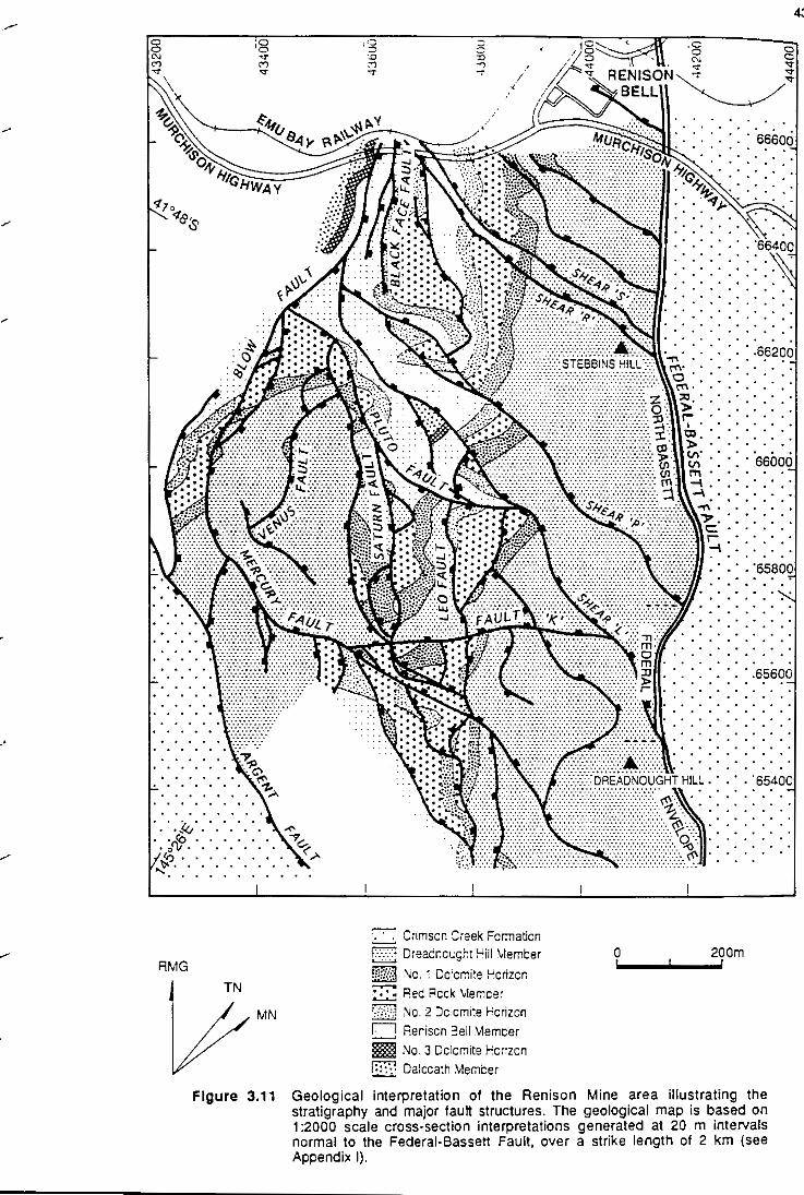
..-
-
/
~
l
RMG
i5 .., ..,. /
4:'
g .,. .,. .,.
.......... 65600
TN
MN
==:;: Ctlmscn Creek Fcrmaticn f:·:::::::' Dreacnccgct !Cill \lemt:er ;.:.-:.:·1 'I.'C , Dc·c~·,te~ uc'IZCn ,:,::•:", l'i , , lol '"'I, 0 I
~ Rec! Reck \lemcer ::-':i::.i.:1 ~a. 2 Dc:cmite Hcrizcn
U Reriscn 3eil \lemcer l!im :-<o. 3 Dele mite rcrizcn l::::i Dalccath .\1emCer
0 200m
Figure 3.11 Geological interpretation of the Renison Mine area illustrating the stratigraphy and major tau~ structures. The geological map is based on 1 :2000 scale cross-section interpretations generated at 20 m intervals normal to the Federal-Bassett Fault, over a strike length of 2 km (see Appendix I}.
cross-section interpretations, level plans, and ore reserve estimates were consulted. It was
necessary to generate new 1 :500 scale cross-sections in complex areas of the mine.
The 1:2000 scale geological interpretations for each cross-sections were then digitised
using Datamine software at Renison. Due to the limitations of the software package,
wireframing of the complex Renison geology was only partially successful. Appendix I
includes a complete set of the digitised cross-section interpretations for the Renison Mine.
3.5.3 Fault Structures And Mineralisation
3.5.3.1 First Order Structures •..
The principle structure at Renison was the Federal-Bassett Fau~ which provided the major
focus for hydrothermal fluid flow and vein deposHion (Fig. 3.10 & 3.11 ). The Blow Fault was
another first order structure, and forms the western boundary to economic tin mineralisation
at Renison (Fig. 3.10 & 3.11 ).
Federal-Bassett Fault
The Federal-Bassett Fau~ has a strike length of atleast10 km (Lea, 1991) and dips between
55° and 70° to the NE along the eastern margin of the Renison mine horst (Fig. 3.9). It forms
a double-fault structure, or fault pair, with the hangingwall and footwall faults typically
separated by less than 10 m, a~hough up to 60 m of separation is known. In the mine area,
the region between the hangingwall and footwall of Federal-Bassett Fault can be divided
into three distinct zones (Fig. 3.11 ):
(i) Envelopes; the region south of the 'Shear L' - Federal-Bassett Fault intercept.
(ii) Federal; the region between the 'Shear L' and 'Shear P' intercepts wHh the Federal
Bassett Fau~.
(iii) North Bassett; the region north of the 'Shear P' - Federal-Bassett Fault intercept.
In the North Bassett region, the Federal-Bassett Fau~ and the monoclinal fold of the mine
sequence, closely resemble structures described by AI Kadhi and Hancock (1980) in the
Persian GuH (Fig. 3.12a, b), where planar high angle normal boundary fau~s are intimately
associated wHh subsidiary antHhetic and synthetic normal fau~s. Such fau~ patterns typically
characterise terrains that have experienced minor inhomogeneous extensions (Wernicke
and Burchfiel, 1982). Cross-section reconstructions for the North Bassett region of the
Federal-Bassett Fault confirm this interpretation, because extension in the vertical plane
between the hangingwall and footwall faults varies between 15% and 30% (Fig. 3.13).The
44

(a)
Ultnlloll fiiUif
tal-lei> J!IUII
principal 4rabtn
bound«r fault
onlllhtllc normCII foul!
synthetic foul!
fAULTED MONOCLINE ANO ASSOCIATED SrRUCTVRES
sw _,
"""'-
~
0200"'"-
oooo .......
•oo-..
(b)
~ADNO<AHr
.,,LL
..___ • ~\
GRANITE • "" ' •
NE
CRIMSON CREEK FORMATION
MilE SECll..EN::E
SUCCESS CREEK FORMATION
-NI-UMITI:O
RENISON CROSS SECTION
Figure 3.12a Generalised cross-section of a faulted monocline and associated structures, developed in terrains that experience minor inhomogeneous extension. The planar high angle normal bou11dary faults are intimately associated with subsidiary antithetic and synthetic niormal fauHs.
(After AI Kadhi & Hancock, 1980)
Figure 3.12b Cross-section of the North Bassett area (67000N), illustrating the planar high angle normal boundary faults of the Federal-Bassett Fault and minor subsidiary ant~hetic and synthetic normal fauHs related to minor inhomogeneous extension on the eastern limb of the failed monoclinal fold.
(After McQuitty, 1991)
\
~

w 0 0
"' c:;
I2200RL
·-· ... ....... -.... _
sw
w 0 0 0
~
··.··.·.··•···~~{Ddt~ITE
I N'2 DOLOMITE
w 0 0
"' ... ...
··.::;;;·,
w 0 0
~
NE :~'::; ";";;\-.,;,; :::::::::·~:·: :~_";: ;;;
2200RL
I ii2000RL I N"3 DOLOMITE < 1\;& I I 2000RLj
1BOORL
w 0 0
(a)~
w g ~
w 0 0
~
1BOORL
(b)
RECONSTRUCTION OF NORTH BASSETT CROSS-SECTION 67060N
sw
" N'1 DOLOMITE '>. .df/' ' ' ,-N;2DOLOMITE~
N'3 DOLOMITE ·===t===-l k::::::t=ll
0
METRES
200 -i
NE
Figure 3.13a Cross-section of the North Bassett area (67060N) illustrating the planar high angle normal boundary fauijs of the Federal-Bassett Fault and minor subsidary antithetic and synthetic normal faults related to minor inhomogeneous extension on the eastern limb of the failed monocline.
Figure 3.13b Reconstruction of the North Bassett cross-section 67060N where approximately 20% extension of the mine sequence occurred over the failed monocline between the planar high angle normal boundary faults of the Federal-Bassett Fault and minor subsidary ant~hetic and synthetic normal faults. t

percentage of extension in the Envelope and Federal regions is uncertain, due to the
complex nature of fauHing, but is likely to be of a similar order of magn~ude.
The hangingwall to the Federal-Bassett FauH in the mine area is continuous along strike
except for minor late stage fault offsets. The footwall structure, in comparison, is variable in
nature, and responsible for jn~iating the Transverse and other minor fauHs from flexures
within the footwall structure (Fig. 3.10).
Normal-dextral displacement of the hangingwall mine sequence relative to the footwall mine
sequence resulted in approximately 700m of dip-slip movement on the Federal-Bassett
Fault in the North Bassett region (Figs. 3.9 & 3.12b; McQuitty, 1991). Dip-slip movement on
the Federal-Bassett Fault decreases northward to less than 400m at 67500 N (Fig. 2.2;
Marjoribanks, 1990). Toward the south granite sloping of the Federal-Bassett Fault
hangingwall at depth in the Federal area prevents an accurate estimation of the fauH offset.
Blow Fault Complex
The Blow Fault Complex is a continuous north to northwest trending, east dipping fauH
structure that occurs west of, and subparallel to the Federal-Bassett Fault (Fig. 3.11 ). Similar
structures involving the Blow Fault have previously been termed the Western Boundary
Fault (Davies, 1985) and the Footwall FauH (Marjoribanks, 1989). The Blow Fault Complex
occurs approximately 1 km west of the Federal-Bassett FauH south of the mine, and is
terminated by the Argent Fault (Fig. 3.11; Appendix I, 65680N to 65800N). The change in
strike of the Blow Fault Complex is associated w~h a dextral kink fold that affects the mine
horst and accentuates the dilational jog on the Federal-Bassett FauH (Figs. 2.2 & 3.11 ). The
Blow Fault Complex and Federal-Bassett Fault serve as boundary faults to the
interconnecting Transverse FauHs; neither fauH is truncated by the Transverse Fauns (Fig.
3.11 ). North of the study area, the Blow FauH Complex merges with the Federal-Bassett
Fault at 68000 N (Fig. 2.2).
The Blow Fault Complex was initiated, together w~h the other major fauHs at Renison, by
normal-dextral movement. Dip-slip displacement was of the order of a several tens of metres
(Appendix I, 65680N to 65800N). Dextral wrench movement strongly overprints the earlier
generation of normal-dextral fauH striations in the Black Face Opencut and railway exposures
(Plate 3.2a, b; Fig 3.11 ). These features support Marjoribanks' (1990) argument that some of
the high strain on the Federal-Bassett Fault was transferred to the Blow Fault Complex
during reactivation by the regional Taberraberran wrench event. Dextral-wrench movement
on the southern extensions of the Blow FauH Complex was minor, as it is terminated by, and
does not offset the Argent Fault (Fig. 3.11; Appendix I, 65680N to 65800N).
4'

----
/
.-'
.....
.....
The Blow Fault Complex was a minor conduit to mineralising fluids at Renison. It did not
undergo the same degrees of brittle deformation, displacement or dilation that characterise
the Federal-Bassett Fault structure. The Blow Fault Complex appears to have been
important, however, in providing fluid access to the upper extensions of the mine
sequence, assisting the formation of stratabound carbonate replacement orebodies (Fig .
3.14; Argent and Ring).
3.5.3.2 Second Order Structures •.•
Transverse Faults
The Transverse FauHs are a series of east-west trending, shallow to steeply north-east
dipping fauHs that interconnect but do not truncate the two first order structures; the
Federal-Bassett FauH and Blow FauH Complex. South to north in the study area they are
called the Mercury Fautt, 'Shear L', 'Shear P', 'Shear R', and 'ShearS' (Fig. 3.11).
In cross-section {Fig. 3.1 0), the Transverse Fautts form a listric extensional fautt system and
act as basal detachment fautts to third order fautt structures. The Transverse Fautts splayed
off convex-west flexures in the footwall of the Federal-Bassett Fautt (Fig. 3.1 0; Appendix I,
65860N to 66020N). They were in~iated as secondary reverse fauHs, relative to the Federal
Bassett Fautt, during normal-dextral fautting (Section 3.4.4.2; Fig. 3.5). Normal-dextral brittle
deformation on the Federal-Bassett FauH and Blow FauH Complex, inijiated by granite
emplacement, produced local uplift and north-south stretching of the mine horst via the
extensional Transverse FauHs. The magn~ude of north-south crustal extension during
gran~e emplacement is estimated at 15%.
In plan, the Transverse Fautts exhibit a slightly sigmoi:lal trace; a primary feature analogous to
the helicoidal structures related to extensional negative flower structures (Figs. 3.11, 3.14,
3.15; Harding, 1985; Woodcock and Fischer, 1986; Naylor et. a/., 1986). An overprinting
weak dextral kink fold across the mine horst accentuates the sigmoidal outline of 'Shear P'
and 'Shear L' at the contacts wijh the Federal-Bassett and Blow FauHs (Figs. 3.11, 3.14).
Surface expressions of the Transverse FauHs in the studly area are poor, but 'Shear L' can be
observed near the Federal Open-<:ut on Stebbins Hill (Fig. 2.2), and 'Shear R' in the Black
Face Open-<:ut on the Murchison Highway (Fig. 3.11 ). At this location 'Shear R' has been
interpreted as a low angle thrust (Marjoribanks, 1990), but first and second generation fibres
on fault surfaces are consistent with normal-dextral and dextral-wrench movements,
discounting the possibil~ of an earlier thrust event Mhin the studly area. Shears 'R' and 'S'
have only minor displacements relative to the other Transverse Fautts.
48

SULPHIDE REPLACEMENT OF N0.3 DOLOMITE (FOOlWALL PROJECTION)
66500 N
65 500 N
Figure 3.14
RMGN
tl"
w 8 tt)
(") '<t
0 200m
SCALE
66 500 N
66 000 N
Footwall projection of the No. 3 Dolomite horizon in the Renison Mine illustrating the complex nature of faulting. Breaks in the continuity of the dolomite horizon are the result of fault off-sets. Stratabound carbonate replacement orebodies associated with the No. 3 Dolomite are indicated in red. (RMGN - Renison mine grid north)

Footwall projections of the dolom~e horizons illustrate the complex nature of fauHing, and
show fault gaps due to second and third order fault structures (Fig. 3.14). Sulfide
replacement of the dolom~e horizons was greatest in the lower pressure areas, adjacent to
dilational jogs associated wijh convex flexures w~in the sigmoidal second order Transverse
FauHs. Hydrothermal ore fluids were preferentially focussed into these dilational regions
facimating carbonate replacement mineralisation (Fig. 3.14; e.g., Penzance and Colebrook
orebodies of the No.3 Dolomfte Horizon; Sibson eta/., 1975; Sibson, 1987).
The Melba Fracture Orebody is an anastomosing sheeted vein complex hosted by the
Lower Renison Bell Formation smstones. The orebody has an anticlinal morphology in cross
section and is located between Shear 'L' and 'P' from 65780N to 65980N (Appendix 1). It is
developed above a convex west flexure in the Federal-Bassett FauH between 1800m R.L.
and 1900m R.L. and is bounded to the north by the footwall of 'Shear P' (Fig. 3.1 0). In plan
view, the Melba Orebody splays out from 'Shear P' close to the Federal-Bassett FauH,
creating an orebody which resembles a huge tensional gash opening. The Melba Orebody
is the product of extensional vein openings normal to cr3 during normal-dextral fauHing. It
was later enhanced by differential dextral displacement on 'Shear L' and 'Shear P' during the
dextral wrench reactivation.
Figure 3.15 presents a three dimensional perspective of 'Shear P' from an azimuth of 40°,
relative to the Renison mine grid, and at an inclination of 15°. The contact between 'Shear P'
and the Federal-Bassett Fault (F.B.F.) occurs along the left-hand margin of the projection
and the land surface limits the top of the projection. The Blow Fault Complex terminates the
projection to the right-hand side, and the absence of drill hole data limits an extension of the
projection to lower levels. Along the contact between 'Shear P' and the Federal-Bassett
FauH, in Figure 3.15, is the contact wfth the Melba orebody. It is most notable at this location
that 'Shear P' becomes some what anticlinal to accommodate the Melba orebody
immediately beneath it.
The western margin of 'Shear P' terminates against the Blow Fault Complex, and occupies
the same site as the 'Polaris' carbonate-magnetite orebody. Cross-sectional interpretations
for this area indicate that the 'Polaris' orebody is located wfthin a dilational zone, where
'Shear L' has ramped upward into 'Shear P' (Fig. 3.15 & 3.16; Appendix I, 66380N to
66560N).
Polaris' is a bedding-subparallel shear zone that hosts early carbonate-magnetfte and late
replacement pyrrhotite (±pyrite) mineralisation (Simonsen, 1988). These two phases of
mineralisation are associated wfth normal-dextral faulting and dextral-wrench reactivation,
respectively (Chapter 5). Previous investigators (Barber, 1990; Marjoribanks, 1990) have
5C

, (Q" c:: co t.)
~
0'1
~ )>
1\)
(Q -. R :s· ~
3 <D C/J '::T
C/J N. <D ~
0 3 C/J 0 S» ::l
a. c;;· ii) ::l 0 <D ~
0'1 0 3
0 ::D 0 m 3 z CD en en -5· :cO
mz ""0 )>--f
a ::D-....... -cz C'D (') 3: -c:r ::::J
z m
surface
ei-~o\.j>O~
30 View Parameters
View Azimuth: 40 Degrees View Inclination: 15 degrees View distance: 2000 metres
V:H = 1:1 Illumination Azimuth: 120 degrees Illumination Inclination: 25 degrees
\ \
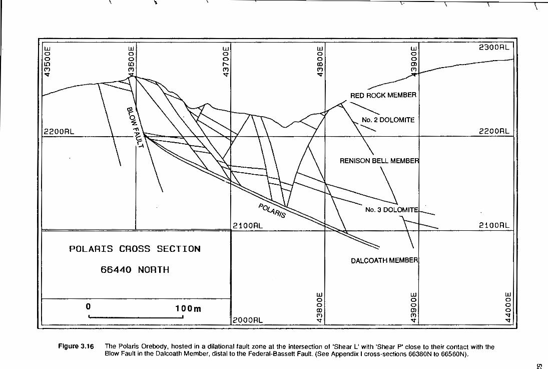
w 0 0 10 (T) ..,.
UJ 0 0 (0 (T)
w 0 0 .... (T) ..,.
UJ 0 0 (I) (T) ..,.
.,.
2300RL
RED ROCK MEMBER
2200RL 2200RL
Po 'l.A.Rts
2100RL 2100RL
POLARIS CROSS SECTION
66440 NORTH
0 1OOm 2000RL
UJ 0 0 (I) (T) '<t
DALCOATH MEMBER
UJ 0 0 Cl [T)
'<t
Figure 3.16 The Polaris Orebody, hosted in a dilational fault zone at the intersection of 'Shear L' with 'Shear P' close to their contact with the Blow Fault in the Dalcoath Member, distal to the Federal-Bassett Fault. (See Appendix I cross-sections 66380N to 66560N).
UJ a 0 a '<t ..,.
"' "'

proposed a pre-Devonian low angle thrust to accommodate 'Polaris' type mineralisation but
such mechanisms are not supported by field observations or cross-section reconstructions.
3.5.3.3 Third Order Structures ...
The second order listric extensional Transverse Fauns acted as basal detachments to a
system of linked third order faults which exhib~ both synthetic and ant~hetic displacements
(Fig. 3.1 0; Appendix 1). The third order structures produced a series of minor horst and
grabens across the mine horst, east of the Blow Faun Complex, striking subparallel to the
Federal-Bassett Fault and normal to 03 associated with normal-dextral br~tle deformation
(Fig. 3.11 ). Regularly spaced cross-section reconstructions for this region indicate that east
west extension, due primarily to second and third order structures, was approximately 20%
(Fig. 3.17). North of 'Shear P' extension associated w~h 'Shear R' and 'ShearS' decreased
to approximately 5%.
In plan, the third order faun structures caused extensive brittle deformation of dolomite
horizons, particularly in the updip areas distal to the Federal-Bassett Faun (Fig. 3.14). These
structures controlled carbonate replacement mineralisation within the Updip dolomite
horizons by providing access for the mineralising solutions. The formation of the Ring,
Argent and Sligo orebodies in the Number 3 Dolomite Horizon appears to be strongly
dependent on these third order structures distal to the Federal-Bassett Fault (Fig. 3.14).
3.5.3.4 Granite Topography ...
Lea (1991) proposed that movement on the Federal-Bassett Faun at Renison was in~iated in
a tensional regime associated with grantte emplacement; based on a gravity model for the
granite profile (Leaman, 1990). The grav~y response of the granite (average dens~y 2.66)
indicates that a lower denstty gran~e phase (average denstty 2.64) occurs at two locations;
directly beneath the Renison Mine, and at Pine Hill (Leaman, pers. comm., 1991 ). This
supports the argument of Kwak (1987) that the plimary source of mineralising fluids is a small
granite cupola down-dip from the Federal section of the Federal-Bassett Faun, rather than
the Pine Hill greisen which occurs 400m topographically above and 2.5 km south of the "
Renison Mine.
In shallow plutons fluid overpressure develops due to crystallisation reactions in hydrous
melts (Burnham, 1979; and Heinrich, 1990). Pos~ive volume changes of several tens of
percent cause the hydrostatic pressure to exceed the l~hostatic load, resulting in hydraulic
fracturing. Failure of the country rocks in the direction of CJ3, occur at the points of highest
curvature between the granite and host rock associated wtth the granite cupola, where
5~

w 0 0 0
';/
sw w 0 0 ... ';/
w 0 0 <D ';/
w g
~
w 0 0
~ ... w 0 0
"' ~ NE
w 0 0 ... ~
220UnL \"'-,'\--- '-?'>. 1.-.nuum
"" '& <;
rl I I I ... I I ~ ~\'t-1 'oo""' sw [ ~~ NE I \\f~
RECONSTRUCTION OF MINE CROSS-SECTION 65740 NORTH
10oonL
=== W2 DOLOMITE
0 200
MEmEs
Figure 3.17a Mine cross-section at 65740N illustrating the complex synthetic and antithetic fault development above the Transverse Faults which acted as basal detachments. The synthetic and antithetic fault structures resulted in a complete series of NW-trending minor hurst and graben structures across the mine hurst.
Figure 3.17b A reconstnJction of the 65740N cross-section where approximately 25% extension of the mine sequence resuijed from horst and graben development related to the tailed monocline. 'C.

curvature between the granite and host rock associated w~h the granite cupola, where
stresses are concentrated. The first order Federal-Bassett Fault propagated as a normal
dextral fauij along the steep asymmetrical eastern margin of the shallow northwest plunging
Pine Hill Granite ridge, subparallel to the -500 and -2000 gran~e contours (Figs. 3.9, & 3.18),
in a zone of structural weakness associated with a pre-existing fold limb. During granite
emplacement the Blow Fault Complex and the Transverse Faults were also initiated, and
developed over the eastern extension of the asymmetrical gran~e ridge.
In the study area, the Blow Fauij Complex developed subparallel to the north-south trending
-500 gran~e contour, supporting the close association between major faults and granite
topography (Fig. 3.18). The asymmetrical shape of the gran~e ridge, outlined by the -500
gran~e contour, may explain why the Blow Fauij Complex subparallels or terminates against
the Federal-Bassett Fauij north of the study area at 68000 N and only has a few tens of
metres displacement in comparison to the Federal-Bassett Fauij (Fig. 3.18).
The second order, listric extensional Transverse Faults mimic the gran~e topography. The
Transverse Faults closely parallel the east-west trend of the -500, -1000 and -1500 metre
gran~e contours and plunge to the north (Fig. 3.18).
Third order horst and grabens developed as a consequence of both synthetic and ant~hetic
displacements above the basal listric extensional Transverse Faults (Section 3.5.3.3). The
third order structures resuijed from east-west extension along the eastern margin of the
asymmetrical gran~e ridge where the -500 and -1000 granne contours strike east-west (Fig.
3.18). Extension in this region may have resulted from the emplacement and positive
volume expansion of a late stage granne phase directly beneath the mine area in the region
of the apophysis in the -500 grantte contour (see Chapter 4, Fig. 4.5). Supportive evidence
for a late stage intrusion with a positive volume change can be observed in Figure 4.5 as a
large anomalous bulge on the side of the granite intrusion beneath Renison. This
interpretation is supported by geophysical data which indicates a lower density phase in the
granite at this point (Leaman, pers. comm.", 1991 ), and by granite geochemistry which
defines a tourmaline rich core, an intermediate sericite zone, and an outer albtte halo in the
granne underlying the mine (Bajwah et. at., in press).
The fault patterns associated wtth the underlying granite topography resulted from the
stress field, related to granite emplacement, overlapping with the regional Taberraberran
stress field. The compounding effect of both stress fields was sufficient to initiate normal
dextral brittle deformation. The early stages of casstterite mineralisation were coeval to this
event. Ode (1957) has invoked a similar superpos~ion of local and regional stress fields to
55

r---------------------------------------------------~56 40000E .--- 41000E 42000E -I
i' 43000E 44000E 45000E
81 I I Y . I \ \k ~~ m x 71 ;:::-----1\ \ ~~
gl 76//'--1 ~. 1\ \ \I \ I~ ~ / )/ I Y l I \ \ ~ \~
§ \ 1-; \
~ \ \ z
g I I ..r f I 0 -+' -'-----'-----L.,-! R I 'I I i ~ I " <D , I I , 1
I i I
g \ I I I I
~I\ !t'~~
2! 0 0 z
i I . ._........
81 I \I / 1 I r l ~~ ~ 1 /! ~ i ) ~
/ 1~1" gl , /r ,r,\.. \ ! ' I* ~ I I I J J I "'--\ \ I ~~
I ,c:: R PINE HILL .
~r \ 40000E 41000E 42000E 43000E 44000E 45000E
Location Diacrram 0
FAULTS AND GRANITE CONTOURS
R~G
TN
o 1000 m
Figure 3.18 Granite contours for the Northwest trending Pine Hill Granite ridge underlying the Renison Mine. Overlying the granite contours are the fault outlines from the Renison Mine area (see Fig. 3.11 ). and the approximate location of the Federal-Bassett Fault'granite contact along the eastern margin of the ridge.

explain the observed patterns of faults and dyke emplacements seen above a granite
intrusion in the Spanish Peaks area, Colorado.
As the stress field associated with the granite decayed, the earlier brittle deformation
structures were overprinted by a dextral wrench consistent with the regional Taberraberran
pattern of fautting and reactivation.
3.5.4 Summary Of The Structural Controls To Mineralisation
A detailed geological interpretation of the geology at the Renison Tin Mine using cross
section interpretations and computer modelling has demonstrated a close association
between granite emplacement and brittle deformation structures.
At Renison, Devonian D1 east-west compression associated with the West Coast
RangeNalentines Peak Trend resutted in broad scale tilting of the sediments to the east
(Fig. 3.19a}. D2 northeast-southwest compression overprinted the D1 structures and
produced the open northwest trending Renison Bell Anticline as part of the
Zeehan/Gormanston Trend (Fig. 3.19b).
Many of the structural complexities at Renison resutted from the forceful emplacement in the
Mid- Devonian of the asymmetrical northwest-trending Pine Hill Granite at the intersection of
the Renison Bell Anticlinal high with the Serpentine Hill Uttramafic Complex (Fig. 3.19c}. A
brittle (-ductile} deformation event (D3- part one} associated with emplacement of the Pine
Hill Granite initiated normal-dextral faults subparallel to the granite topography in the
overlying late Precambrian Success Creek Formation and early Cambrian Crimson Creek
Formation. The Federal-Bassett Fault was propagated as a double fault structure on the
eastern margin of the granite, offsetting the monoclinal mine sequence by up to 700m in the
mine area. The Federal-Bassett Fault was the primary focus for hydrothermal fluids
responsible for carbonate replacement and vein styles of mineralisation. The Blow Fautt
Complex was initiated subparallel to the Federal-Bassett Fautt over an apophysis in the
granite contours, forming the western boundary to economic cassiterite mineralisation at
Renison. The Transverse Faults interconnect the Federal-Bassett Fault and Blow Fautt
Complex, subparallel to the east-west trend of the -500 and -1000 granite contours. These
second order listric fault structures propagated from convex-west flexures in the footwall of
the Federal-Bassett Fault and dissected the mine horst, resulting in approximately fifteen
percent north-south extension.
A dextral-wrench reactivation (D3 - part two} overprinted the earlier normal-dextral fautt
structures and produced a dilational jog in the Federal region of the Federal-Bassett Fault as
s7 I

DEVONIAN D1
~ 'rso t10
c::::;::>
A
\-50
'::.-.(/}+'
cl.''l $'
-~· ,:s .. "' c,"'<:l
DEVONIAN D3 (Normal Dextral)
ARGENT FAULT
a1 <F=
02
DEVONIAN D2
P'
8
DEVONIAN D3 (Dextral Wrench)
ss~
a1
p:>
m c
~}, D
va3 STRESS FIELD STRESS FIELD
Figure 3.19 Schematic diagram summarising the main structural events associated w~h Devonian deformation in the Renison area. A: The Devonian D1 event, associated with east-west compression (West Coast/Valentines Peak Trend), produced broad scale titting of the sediments to the east. B: The Devonian D2 event, associated with northeast-southwest compression (Zeehan/Gormanston Trend), produced the northwest trending Renison Bell Anticline and a sigmoidal profile associated with the Serpentine Hill Uttramafic Complex. C: Devonian D3 (i) deformation, associated wtth the forceful emplacement of the Pine Hill Granite at the intersection of the Cambrian UHramafics wtth the Devonian D2 anticinal high, resuHed in the formation of brittle fauH structures on the eastern limb of a failed mcnoclinal fold above a northwest trending grantte ridge. D: The regional Devonian D3 (ii) delormation reactivated lault structures and produced a dextral kink fold across the mine host as a resuH of differential displacement on the Transverse Faults. This event produced the dilational jog in the Federal area of the Federal-Bassett Fault that focussed the hydrothermal fluids responsible for stratabound carbonate replacement mineralisation.

a consequence of differential displacements on the Transverse Faults and the formation of a
weak dextral kink fold (Fig. 3. t9d). The stress field associated w~h the dextral wrench may
also have played a significant role in the formation of the largest carbonate replacement
styles of mineralisation at Renison, which occur in dilational zones adjacent to sigmoidal
convex flexures on the Transverse Fauijs. The Melba Fracture Orebody formed in a dilational
zone in the competent Renison Bell Member, between 'Shear L' and 'Shear P', as a
consequence of normal-dextral faulting and dextral wrench reactivation. Carbonate
magnetite mineralisation in the Polaris Orebody occurs at the western extrem~ of 'Shear P'
in a dilational zone created by the intersection of 'Shear L'.
Third order, north-south striking, horst and graben structures developed in response to
synthetic and ant~hetic fauijing above basal listric extensional Transverse Faults. The third
order structures resuijed in twenty percent extension of the mine sequence in the direction
of the minimum compressive stress for normal-dextral faulting above an apophysis outlined
by the -500 granite contour. The third order faults controlled the extent of carbonate
replacement mineralisation in the Updip dolomite horizons distal to the Federal-Bassett
FauH.
At Renison, the intimate associations between brittle deformation structures and granite
topography suggest that the Pine Hill Granite forcefully intruded the sediments immediately
beneath the mine during the Middle Devonian. The following chapters will show that in
addition to ground preparation the granite also supplied the Sn-bearing fluids responsible
for carbonate replacement and vein styles of cass~erite mineralisation.
59