Embed Size (px)
Citation preview

1
GEOLOGICAL SURVEY OF DENMARK AND GREENLAND BULLETIN 8 · 2005
Structural analysis of the RubjergKnude Glaciotectonic Complex,Vendsyssel, northern Denmark
Stig A. Schack Pedersen
GEOLOGICAL SURVEY OF DENMARK AND GREENLANDDANISH MINISTRY OF THE ENVIRONMENT

2
Geological Survey of Denmark and Greenland Bulletin 8
Keywords
Northern Jylland, Denmark, Weichselian, glacial geology, glaciotectonics, thin-skinned thrust faulting, balanced cross-section, thrust-fault dynamics, imbricate duplexes, mud diapirs, piggyback basins.
CoverThe coastal clif f (99 m high at its highest point) at Rubjerg Knude on the west coast of Vendsyssel, northern Denmark. The lower
two-thirds of the cliff, beneath the prominent dark sub-horizontal surface, forms part of the cross-section through the RubjergKnude Glaciotectonic Complex displaying imbricated thrust sheets composed of the Lønstrup Klint Formation (bluish-grey colour)
and the overlying Rubjerg Knude Formation (yellow colour), both of Late Weichselian age. The thrust sheets are truncated by aglaciotectonic unconformity (the prominent surface), upon which the Kattegat Till Formation is only preserved as a boulder bed
due to subsequent aeolian erosion of the till matrix. The upper third of the clif f comprises recent aeolian dune sands that haveaccreted over the last 100 years and now encroach on the Rubjerg Knude lighthouse, the top of which is just visible above the
clif ftop. Photo: Stig A. Schack Pedersen (August 1984).
Chief editor of this series: Adam A. Garde
Editorial board of this series: John A. Korstgård, Geological Institute, University of Aarhus; Minik Rosing, Geological Museum,University of Copenhagen; Finn Surlyk, Geological Institute, University of Copenhagen
Scientific editor of this volume: Jon R. InesonEditorial secretaries: Esben W. Glendal and Birgit Eriksen
Illustrations: Benny M. Schark and Alice RosenstandDigital photographic work: Benny M. Schark
Graphic production: Knud Gr@phic Consult, Odense, DenmarkPrinters: Schultz Grafisk, Albertslund, Denmark
Manuscript submitted: 8 August 2003Final version approved: 11 February 2005
Printed: 15 December 2005
This monograph has been accepted by the Faculty of Natural Sciences, University of Copenhagen, for public defence of the degreeof Doctor of Science.
ISSN 1604-8156
ISBN 87-7871-168-1
Geological Survey of Denmark and Greenland Bulletin
The series Geological Survey of Denmark and Greenland Bulletin replaces Geology of Denmark Survey Bulletin and Geology ofGreenland Survey Bulletin.
Citation of the name of this series
It is recommended that the name of this series is cited in full, viz. Geological Survey of Denmark and Greenland Bulletin.If abbreviation of this volume is necessary, the following form is suggested: Geol. Surv. Den. Green. Bull. 8, 192 pp.
Available from
Geological Survey of Denmark and Greenland (GEUS)Øster Voldgade 10, DK-1350 Copenhagen K, Denmark
Phone: +45 38 14 20 00, fax: +45 38 14 20 50, e-mail: [email protected]
Geografforlaget ApSRugårdsvej 55, DK-5000 Odense C, Denmark
Phone: +45 63 44 16 83, fax: +45 63 44 16 97, e-mail: [email protected]
© Danmarks og Grønlands Geologiske Undersøgelse (GEUS), 2005

3
Contents
Abstract . . . . . . . . . . . . . . . . . . . . . . . . . . . . . . . . . . . . . . . . . . . . . . . . . . . . . . . . . . . . . . . 9Introduction . . . . . . . . . . . . . . . . . . . . . . . . . . . . . . . . . . . . . . . . . . . . . . . . . . . . . . . . . . . 11
History of the present investigation . . . . . . . . . . . . . . . . . . . . . . . . . . . . . . . . . . . . . . . 11Objectives . . . . . . . . . . . . . . . . . . . . . . . . . . . . . . . . . . . . . . . . . . . . . . . . . . . . . . . . 14
Glacial tectonics – concepts and models . . . . . . . . . . . . . . . . . . . . . . . . . . . . . . . . . . . . . 14Previous conceptual models . . . . . . . . . . . . . . . . . . . . . . . . . . . . . . . . . . . . . . . . . . . 14Thin-skinned thrust faulting: the concept . . . . . . . . . . . . . . . . . . . . . . . . . . . . . . . . . . . . 16
Thrust-fault modelling . . . . . . . . . . . . . . . . . . . . . . . . . . . . . . . . . . . . . . . . . . . . . . . . 16Test model 1. . . . . . . . . . . . . . . . . . . . . . . . . . . . . . . . . . . . . . . . . . . . . . . . . . . . 19Test model 2 . . . . . . . . . . . . . . . . . . . . . . . . . . . . . . . . . . . . . . . . . . . . . . . . . . . . 19Test model 3 . . . . . . . . . . . . . . . . . . . . . . . . . . . . . . . . . . . . . . . . . . . . . . . . . . 21Test model 4 . . . . . . . . . . . . . . . . . . . . . . . . . . . . . . . . . . . . . . . . . . . . . . . . . . 21Test models: concluding remarks . . . . . . . . . . . . . . . . . . . . . . . . . . . . . . . . . . . 22
Concept of balanced cross-section . . . . . . . . . . . . . . . . . . . . . . . . . . . . . . . . . . . . 22Location and construction of the Rubjerg Knude cross-section . . . . . . . . . . . . . . . . . 23
Location. . . . . . . . . . . . . . . . . . . . . . . . . . . . . . . . . . . . . . . . . . . . . . . . . . . . . . . . . . . 23Photogrammetric work. . . . . . . . . . . . . . . . . . . . . . . . . . . . . . . . . . . . . . . . . . . . . . . . 23Digital editing . . . . . . . . . . . . . . . . . . . . . . . . . . . . . . . . . . . . . . . . . . . . . . . . . . . . . 25Construction of the balanced cross-section . . . . . . . . . . . . . . . . . . . . . . . . . . . . . . . . 26
Geological setting . . . . . . . . . . . . . . . . . . . . . . . . . . . . . . . . . . . . . . . . . . . . . . . . . . . . . . . 27Lithostratigraphy. . . . . . . . . . . . . . . . . . . . . . . . . . . . . . . . . . . . . . . . . . . . . . . . . . . . . . . 33
Skærumhede Group . . . . . . . . . . . . . . . . . . . . . . . . . . . . . . . . . . . . . . . . . . . . . . . . . . 33Stortorn Formation . . . . . . . . . . . . . . . . . . . . . . . . . . . . . . . . . . . . . . . . . . . . . . . . 35Lønstrup Klint Formation . . . . . . . . . . . . . . . . . . . . . . . . . . . . . . . . . . . . . . . . . . . . 39
Upper Weichselian lithostratigraphic units . . . . . . . . . . . . . . . . . . . . . . . . . . . . . . . . . . 43Rubjerg Knude Formation . . . . . . . . . . . . . . . . . . . . . . . . . . . . . . . . . . . . . . . . . . . 43Kattegat Till Formation . . . . . . . . . . . . . . . . . . . . . . . . . . . . . . . . . . . . . . . . . . . . . 48Ribjerg Formation . . . . . . . . . . . . . . . . . . . . . . . . . . . . . . . . . . . . . . . . . . . . . . . . . 50Mid Danish Till Formation . . . . . . . . . . . . . . . . . . . . . . . . . . . . . . . . . . . . . . . . . . . 53Vendsyssel Formation . . . . . . . . . . . . . . . . . . . . . . . . . . . . . . . . . . . . . . . . . . . . . . 55
Structural description of sections . . . . . . . . . . . . . . . . . . . . . . . . . . . . . . . . . . . . . . . . . . 60Ulstrup Section . . . . . . . . . . . . . . . . . . . . . . . . . . . . . . . . . . . . . . . . . . . . . . . . . . . . . 60
Tectonic architecture . . . . . . . . . . . . . . . . . . . . . . . . . . . . . . . . . . . . . . . . . . . . . . 61Sedimentary units . . . . . . . . . . . . . . . . . . . . . . . . . . . . . . . . . . . . . . . . . . . . . . 62Lønstrup Klint Formation . . . . . . . . . . . . . . . . . . . . . . . . . . . . . . . . . . . . . . . . 62Rubjerg Knude Formation . . . . . . . . . . . . . . . . . . . . . . . . . . . . . . . . . . . . . . . . 63
Structures and breccias . . . . . . . . . . . . . . . . . . . . . . . . . . . . . . . . . . . . . . . . . . . . 63Thrust-zone breccias . . . . . . . . . . . . . . . . . . . . . . . . . . . . . . . . . . . . . . . . . . . . 64Foreland-dipping hanging-wall flat faults . . . . . . . . . . . . . . . . . . . . . . . . . . . . . 64Collapse structure in the Ulstrup Rende . . . . . . . . . . . . . . . . . . . . . . . . . . . . . 66
Interpretation of structural development . . . . . . . . . . . . . . . . . . . . . . . . . . . . . . . . 66Stensnæs Section . . . . . . . . . . . . . . . . . . . . . . . . . . . . . . . . . . . . . . . . . . . . . . . . . . . . 70
Tectonic architecture . . . . . . . . . . . . . . . . . . . . . . . . . . . . . . . . . . . . . . . . . . . . . . 70Sedimentary units . . . . . . . . . . . . . . . . . . . . . . . . . . . . . . . . . . . . . . . . . . . . . . . . . 72
Lønstrup Klint Formation . . . . . . . . . . . . . . . . . . . . . . . . . . . . . . . . . . . . . . . . . 72Rubjerg Knude Formation . . . . . . . . . . . . . . . . . . . . . . . . . . . . . . . . . . . . . . . . 73
Structures . . . . . . . . . . . . . . . . . . . . . . . . . . . . . . . . . . . . . . . . . . . . . . . . . . . . . . . 73

4
Imbricate duplex folding . . . . . . . . . . . . . . . . . . . . . . . . . . . . . . . . . . . . . . . . . . . 73Extensional faults . . . . . . . . . . . . . . . . . . . . . . . . . . . . . . . . . . . . . . . . . . . . . . . . 73
Interpretation of structural development . . . . . . . . . . . . . . . . . . . . . . . . . . . . . . . . 78Martørv Bakker Section . . . . . . . . . . . . . . . . . . . . . . . . . . . . . . . . . . . . . . . . . . . . . . . 78
Tectonic architecture . . . . . . . . . . . . . . . . . . . . . . . . . . . . . . . . . . . . . . . . . . . . . . 79Sedimentary units . . . . . . . . . . . . . . . . . . . . . . . . . . . . . . . . . . . . . . . . . . . . . . . . . . 80
Lønstrup Klint Formation . . . . . . . . . . . . . . . . . . . . . . . . . . . . . . . . . . . . . . . . . 81Rubjerg Knude Formation . . . . . . . . . . . . . . . . . . . . . . . . . . . . . . . . . . . . . . . . . 81
Structures . . . . . . . . . . . . . . . . . . . . . . . . . . . . . . . . . . . . . . . . . . . . . . . . . . . . . . . 82Imbricate duplexes . . . . . . . . . . . . . . . . . . . . . . . . . . . . . . . . . . . . . . . . . . . . . . 82Normal fault . . . . . . . . . . . . . . . . . . . . . . . . . . . . . . . . . . . . . . . . . . . . . . . . . . . 82Hydrodynamic brecciation . . . . . . . . . . . . . . . . . . . . . . . . . . . . . . . . . . . . . . . . . 82
Interpretation of structural development . . . . . . . . . . . . . . . . . . . . . . . . . . . . . . . . . . 82Kramrende Section . . . . . . . . . . . . . . . . . . . . . . . . . . . . . . . . . . . . . . . . . . . . . . . . . . . 84
Tectonic architecture . . . . . . . . . . . . . . . . . . . . . . . . . . . . . . . . . . . . . . . . . . . . . . . 85Sedimentary units . . . . . . . . . . . . . . . . . . . . . . . . . . . . . . . . . . . . . . . . . . . . . . . . . . 86
Lønstrup Klint Formation . . . . . . . . . . . . . . . . . . . . . . . . . . . . . . . . . . . . . . . . . . 87Rubjerg Knude Formation . . . . . . . . . . . . . . . . . . . . . . . . . . . . . . . . . . . . . . . . . 87
Structures . . . . . . . . . . . . . . . . . . . . . . . . . . . . . . . . . . . . . . . . . . . . . . . . . . . . . . . . 87Thrust faults . . . . . . . . . . . . . . . . . . . . . . . . . . . . . . . . . . . . . . . . . . . . . . . . . . . . 87Kramrende diapir . . . . . . . . . . . . . . . . . . . . . . . . . . . . . . . . . . . . . . . . . . . . . . . . 88Reverse faults . . . . . . . . . . . . . . . . . . . . . . . . . . . . . . . . . . . . . . . . . . . . . . . . . . 88
Interpretation of structural development . . . . . . . . . . . . . . . . . . . . . . . . . . . . . . . . 89Brede Rende Section . . . . . . . . . . . . . . . . . . . . . . . . . . . . . . . . . . . . . . . . . . . . . . . . . . 90
Tectonic architecture . . . . . . . . . . . . . . . . . . . . . . . . . . . . . . . . . . . . . . . . . . . . . . . 90Sedimentary units . . . . . . . . . . . . . . . . . . . . . . . . . . . . . . . . . . . . . . . . . . . . . . . . . 93
Lønstrup Klint Formation . . . . . . . . . . . . . . . . . . . . . . . . . . . . . . . . . . . . . . . . . 93Rubjerg Knude Formation . . . . . . . . . . . . . . . . . . . . . . . . . . . . . . . . . . . . . . . . . 94
Structures . . . . . . . . . . . . . . . . . . . . . . . . . . . . . . . . . . . . . . . . . . . . . . . . . . . . . . . 94Diapir structures . . . . . . . . . . . . . . . . . . . . . . . . . . . . . . . . . . . . . . . . . . . . . . . . 96Brede Rende normal fault . . . . . . . . . . . . . . . . . . . . . . . . . . . . . . . . . . . . . . . . . 97Frost wedges . . . . . . . . . . . . . . . . . . . . . . . . . . . . . . . . . . . . . . . . . . . . . . . . . . 97
Interpretation of structural development . . . . . . . . . . . . . . . . . . . . . . . . . . . . . . . . 97Sandrende Section . . . . . . . . . . . . . . . . . . . . . . . . . . . . . . . . . . . . . . . . . . . . . . . . . . . 99
Tectonic architecture . . . . . . . . . . . . . . . . . . . . . . . . . . . . . . . . . . . . . . . . . . . . . . . . . 99Sedimentary units . . . . . . . . . . . . . . . . . . . . . . . . . . . . . . . . . . . . . . . . . . . . . . . . . . . 101
Lønstrup Klint Formation . . . . . . . . . . . . . . . . . . . . . . . . . . . . . . . . . . . . . . . . . . . 101Rubjerg Knude Formation . . . . . . . . . . . . . . . . . . . . . . . . . . . . . . . . . . . . . . . . . . . 101
Structures and breccias . . . . . . . . . . . . . . . . . . . . . . . . . . . . . . . . . . . . . . . . . . . . . . 103Normal faults . . . . . . . . . . . . . . . . . . . . . . . . . . . . . . . . . . . . . . . . . . . . . . . . . . . . 103Diapir structures . . . . . . . . . . . . . . . . . . . . . . . . . . . . . . . . . . . . . . . . . . . . . . . . 104Frost wedge . . . . . . . . . . . . . . . . . . . . . . . . . . . . . . . . . . . . . . . . . . . . . . . . . . . 104
Interpretation of structural development . . . . . . . . . . . . . . . . . . . . . . . . . . . . . . . . . 104Stenstue Rende Section . . . . . . . . . . . . . . . . . . . . . . . . . . . . . . . . . . . . . . . . . . . . . . . 105
Tectonic architecture . . . . . . . . . . . . . . . . . . . . . . . . . . . . . . . . . . . . . . . . . . . . . . . . 106Sedimentary units . . . . . . . . . . . . . . . . . . . . . . . . . . . . . . . . . . . . . . . . . . . . . . . . . 107
Lønstrup Klint Formation . . . . . . . . . . . . . . . . . . . . . . . . . . . . . . . . . . . . . . . . . . . 107Rubjerg Knude Formation . . . . . . . . . . . . . . . . . . . . . . . . . . . . . . . . . . . . . . . . . . . 108
Structures . . . . . . . . . . . . . . . . . . . . . . . . . . . . . . . . . . . . . . . . . . . . . . . . . . . . . . . . 108Thrust-fault structures . . . . . . . . . . . . . . . . . . . . . . . . . . . . . . . . . . . . . . . . . . . 108Hanging-wall anticlines . . . . . . . . . . . . . . . . . . . . . . . . . . . . . . . . . . . . . . . . . . . 109

5
Normal faults . . . . . . . . . . . . . . . . . . . . . . . . . . . . . . . . . . . . . . . . . . . . . . . . . . . 110Slump folding . . . . . . . . . . . . . . . . . . . . . . . . . . . . . . . . . . . . . . . . . . . . . . . . . . . 110
Interpretation of structural development . . . . . . . . . . . . . . . . . . . . . . . . . . . . . . . . . . 110Grønne Rende Section . . . . . . . . . . . . . . . . . . . . . . . . . . . . . . . . . . . . . . . . . . . . . . . . . . 111
Tectonic architecture . . . . . . . . . . . . . . . . . . . . . . . . . . . . . . . . . . . . . . . . . . . . . . . . . 112Sedimentary units . . . . . . . . . . . . . . . . . . . . . . . . . . . . . . . . . . . . . . . . . . . . . . . . . . . 112
Lønstrup Klint Formation . . . . . . . . . . . . . . . . . . . . . . . . . . . . . . . . . . . . . . . . . . . 112Rubjerg Knude Formation . . . . . . . . . . . . . . . . . . . . . . . . . . . . . . . . . . . . . . . . . . 112
Structures . . . . . . . . . . . . . . . . . . . . . . . . . . . . . . . . . . . . . . . . . . . . . . . . . . . . . . . 113GR01 thrust sheet . . . . . . . . . . . . . . . . . . . . . . . . . . . . . . . . . . . . . . . . . . . . . . . . 113GR02 thrust sheet . . . . . . . . . . . . . . . . . . . . . . . . . . . . . . . . . . . . . . . . . . . . . . . . 114GR03 thrust sheet . . . . . . . . . . . . . . . . . . . . . . . . . . . . . . . . . . . . . . . . . . . . . . . . 114GR04 thrust sheet . . . . . . . . . . . . . . . . . . . . . . . . . . . . . . . . . . . . . . . . . . . . . . . . 114GR05 thrust sheet . . . . . . . . . . . . . . . . . . . . . . . . . . . . . . . . . . . . . . . . . . . . . . . . 115GR06 thrust sheet . . . . . . . . . . . . . . . . . . . . . . . . . . . . . . . . . . . . . . . . . . . . . . . . 115GR07 thrust sheet . . . . . . . . . . . . . . . . . . . . . . . . . . . . . . . . . . . . . . . . . . . . . . . . 116GR08 thrust sheet . . . . . . . . . . . . . . . . . . . . . . . . . . . . . . . . . . . . . . . . . . . . . . . . 116GR09 thrust sheet . . . . . . . . . . . . . . . . . . . . . . . . . . . . . . . . . . . . . . . . . . . . . . . . 116GR10 thrust sheet . . . . . . . . . . . . . . . . . . . . . . . . . . . . . . . . . . . . . . . . . . . . . . . . 116GR11 thrust sheet . . . . . . . . . . . . . . . . . . . . . . . . . . . . . . . . . . . . . . . . . . . . . . . . 117GR12 thrust sheet . . . . . . . . . . . . . . . . . . . . . . . . . . . . . . . . . . . . . . . . . . . . . . . . 117GR13 thrust sheet . . . . . . . . . . . . . . . . . . . . . . . . . . . . . . . . . . . . . . . . . . . . . . . . 117
Interpretation of structural development . . . . . . . . . . . . . . . . . . . . . . . . . . . . . . . . . . 117Rubjerg Knude Fyr Section . . . . . . . . . . . . . . . . . . . . . . . . . . . . . . . . . . . . . . . . . . . . . 118
Tectonic architecture . . . . . . . . . . . . . . . . . . . . . . . . . . . . . . . . . . . . . . . . . . . . . . . . 118Sedimentary units . . . . . . . . . . . . . . . . . . . . . . . . . . . . . . . . . . . . . . . . . . . . . . . . 121Structures . . . . . . . . . . . . . . . . . . . . . . . . . . . . . . . . . . . . . . . . . . . . . . . . . . . . . . . 122
Anastomosing thrust-fault brecciation . . . . . . . . . . . . . . . . . . . . . . . . . . . . . . . . . 122Interpretation of structural development . . . . . . . . . . . . . . . . . . . . . . . . . . . . . . . . . . 122
Stortorn Section . . . . . . . . . . . . . . . . . . . . . . . . . . . . . . . . . . . . . . . . . . . . . . . . . . . . . . . 122Tectonic architecture . . . . . . . . . . . . . . . . . . . . . . . . . . . . . . . . . . . . . . . . . . . . . . . . 123
ST01 thrust sheet . . . . . . . . . . . . . . . . . . . . . . . . . . . . . . . . . . . . . . . . . . . . . . . . 123ST02 thrust sheet . . . . . . . . . . . . . . . . . . . . . . . . . . . . . . . . . . . . . . . . . . . . . . . . 123ST03 thrust sheet . . . . . . . . . . . . . . . . . . . . . . . . . . . . . . . . . . . . . . . . . . . . . . . . 123ST04 thrust sheet . . . . . . . . . . . . . . . . . . . . . . . . . . . . . . . . . . . . . . . . . . . . . . . . 123ST05 thrust sheet . . . . . . . . . . . . . . . . . . . . . . . . . . . . . . . . . . . . . . . . . . . . . . . . 124ST06 thrust sheet . . . . . . . . . . . . . . . . . . . . . . . . . . . . . . . . . . . . . . . . . . . . . . . . 124ST07 thrust sheet . . . . . . . . . . . . . . . . . . . . . . . . . . . . . . . . . . . . . . . . . . . . . . . . 124ST08 thrust sheet . . . . . . . . . . . . . . . . . . . . . . . . . . . . . . . . . . . . . . . . . . . . . . . . 124ST09 thrust sheet . . . . . . . . . . . . . . . . . . . . . . . . . . . . . . . . . . . . . . . . . . . . . . . . 125ST10 thrust sheet . . . . . . . . . . . . . . . . . . . . . . . . . . . . . . . . . . . . . . . . . . . . . . . . 125
Sedimentary units . . . . . . . . . . . . . . . . . . . . . . . . . . . . . . . . . . . . . . . . . . . . . . . . . . . 126Structures . . . . . . . . . . . . . . . . . . . . . . . . . . . . . . . . . . . . . . . . . . . . . . . . . . . . . . . 126Interpretation of structural development . . . . . . . . . . . . . . . . . . . . . . . . . . . . . . . . . 126
Moserende Section . . . . . . . . . . . . . . . . . . . . . . . . . . . . . . . . . . . . . . . . . . . . . . . . . . . 128Tectonic architecture . . . . . . . . . . . . . . . . . . . . . . . . . . . . . . . . . . . . . . . . . . . . . . . . 128
MR01 thrust sheet . . . . . . . . . . . . . . . . . . . . . . . . . . . . . . . . . . . . . . . . . . . . . . . . 129MR02 thrust sheet . . . . . . . . . . . . . . . . . . . . . . . . . . . . . . . . . . . . . . . . . . . . . . . . 130MR03 thrust sheet . . . . . . . . . . . . . . . . . . . . . . . . . . . . . . . . . . . . . . . . . . . . . . . . 130MR04 and MR05 thrust sheets . . . . . . . . . . . . . . . . . . . . . . . . . . . . . . . . . . . . . . . . 130MR06–MR08 thrust sheets . . . . . . . . . . . . . . . . . . . . . . . . . . . . . . . . . . . . . . . . . . . 131
6
MR09 thrust sheet . . . . . . . . . . . . . . . . . . . . . . . . . . . . . . . . . . . . . . . . . . . . . . . . 132MR10 thrust sheet . . . . . . . . . . . . . . . . . . . . . . . . . . . . . . . . . . . . . . . . . . . . . . . . 132MR11 thrust sheet . . . . . . . . . . . . . . . . . . . . . . . . . . . . . . . . . . . . . . . . . . . . . . . . 132MR12 thrust sheet . . . . . . . . . . . . . . . . . . . . . . . . . . . . . . . . . . . . . . . . . . . . . . . . 132MR13 thrust sheet . . . . . . . . . . . . . . . . . . . . . . . . . . . . . . . . . . . . . . . . . . . . . . . . 133
Sedimentary units . . . . . . . . . . . . . . . . . . . . . . . . . . . . . . . . . . . . . . . . . . . . . . . . . . . 134Lønstrup Klint Formation . . . . . . . . . . . . . . . . . . . . . . . . . . . . . . . . . . . . . . . . . . . 134Rubjerg Knude Formation . . . . . . . . . . . . . . . . . . . . . . . . . . . . . . . . . . . . . . . . . . . 134
Structures . . . . . . . . . . . . . . . . . . . . . . . . . . . . . . . . . . . . . . . . . . . . . . . . . . . . . . . . . 134Diapir structures . . . . . . . . . . . . . . . . . . . . . . . . . . . . . . . . . . . . . . . . . . . . . . . . 135Thrust faults . . . . . . . . . . . . . . . . . . . . . . . . . . . . . . . . . . . . . . . . . . . . . . . . . . . . . 135Footwall synclines . . . . . . . . . . . . . . . . . . . . . . . . . . . . . . . . . . . . . . . . . . . . . . . . 135
Interpretation of structural development . . . . . . . . . . . . . . . . . . . . . . . . . . . . . . . . . . 136Mårup Kirke Section . . . . . . . . . . . . . . . . . . . . . . . . . . . . . . . . . . . . . . . . . . . . . . . . . . . 137
Tectonic architecture . . . . . . . . . . . . . . . . . . . . . . . . . . . . . . . . . . . . . . . . . . . . . . . . 138MK01 thrust sheet . . . . . . . . . . . . . . . . . . . . . . . . . . . . . . . . . . . . . . . . . . . . . . . . 139MK02–MK04 thrust sheets . . . . . . . . . . . . . . . . . . . . . . . . . . . . . . . . . . . . . . . . . . . 139MK05–MK07 thrust sheets . . . . . . . . . . . . . . . . . . . . . . . . . . . . . . . . . . . . . . . . . . . 139MK08–MK10 thrust sheets . . . . . . . . . . . . . . . . . . . . . . . . . . . . . . . . . . . . . . . . . . . 140MK11–MK20 thrust sheets . . . . . . . . . . . . . . . . . . . . . . . . . . . . . . . . . . . . . . . . . . . 140
Sedimentary units . . . . . . . . . . . . . . . . . . . . . . . . . . . . . . . . . . . . . . . . . . . . . . . . . 141Structures . . . . . . . . . . . . . . . . . . . . . . . . . . . . . . . . . . . . . . . . . . . . . . . . . . . . . . . . . 141Interpretation of structural development . . . . . . . . . . . . . . . . . . . . . . . . . . . . . . . . . . 141
Fault-bend-fold model for duplex units . . . . . . . . . . . . . . . . . . . . . . . . . . . . . . . . . 141Characterisation of thrust duplex MK11–MK20. . . . . . . . . . . . . . . . . . . . . . . . . . . . 143Discussion of structural development . . . . . . . . . . . . . . . . . . . . . . . . . . . . . . . . . 143
Ribjerg Section . . . . . . . . . . . . . . . . . . . . . . . . . . . . . . . . . . . . . . . . . . . . . . . . . . . . . . 144‘Store Blå’ and ‘Lille Blå’. . . . . . . . . . . . . . . . . . . . . . . . . . . . . . . . . . . . . . . . . . . . . . . 144Tectonic architecture . . . . . . . . . . . . . . . . . . . . . . . . . . . . . . . . . . . . . . . . . . . . . . . 145Sedimentary units . . . . . . . . . . . . . . . . . . . . . . . . . . . . . . . . . . . . . . . . . . . . . . . . . . 146
Skærumhede Group . . . . . . . . . . . . . . . . . . . . . . . . . . . . . . . . . . . . . . . . . . . . . . . 146Blå-unconformity . . . . . . . . . . . . . . . . . . . . . . . . . . . . . . . . . . . . . . . . . . . . . . . 146Ribjerg Formation . . . . . . . . . . . . . . . . . . . . . . . . . . . . . . . . . . . . . . . . . . . . . . . 146Mid Danish Till Formation . . . . . . . . . . . . . . . . . . . . . . . . . . . . . . . . . . . . . . . . . . 147Vendsyssel Formation . . . . . . . . . . . . . . . . . . . . . . . . . . . . . . . . . . . . . . . . . . . . . . 147
Structures . . . . . . . . . . . . . . . . . . . . . . . . . . . . . . . . . . . . . . . . . . . . . . . . . . . . . . . . . 147Interpretation of glacial geology and stratigraphic development . . . . . . . . . . . . . . . . 147
Dynamic development of the thin-skinned thrust faulting . . . . . . . . . . . . . . . . . . . . . . 148Moserende Section . . . . . . . . . . . . . . . . . . . . . . . . . . . . . . . . . . . . . . . . . . . . . . . . . . . . . 148
Moserende Section: summary data . . . . . . . . . . . . . . . . . . . . . . . . . . . . . . . . . . . . . . . 149Stortorn Section . . . . . . . . . . . . . . . . . . . . . . . . . . . . . . . . . . . . . . . . . . . . . . . . . . . . . . 149
Stortorn Section: summary data . . . . . . . . . . . . . . . . . . . . . . . . . . . . . . . . . . . . . . . . . 156Rubjerg Knude Fyr Section . . . . . . . . . . . . . . . . . . . . . . . . . . . . . . . . . . . . . . . . . . . . . . . 156
Rubjerg Knude Fyr Section: summary data . . . . . . . . . . . . . . . . . . . . . . . . . . . . . . . . . 156Grønne Rende Section . . . . . . . . . . . . . . . . . . . . . . . . . . . . . . . . . . . . . . . . . . . . . . . . . . 156
Grønne Rende Section: summary data . . . . . . . . . . . . . . . . . . . . . . . . . . . . . . . . . . . . 157Stenstue Rende Section . . . . . . . . . . . . . . . . . . . . . . . . . . . . . . . . . . . . . . . . . . . . . . . 157
Stenstue Rende Section: summary data . . . . . . . . . . . . . . . . . . . . . . . . . . . . . . . . . . . 161Sandrende Section . . . . . . . . . . . . . . . . . . . . . . . . . . . . . . . . . . . . . . . . . . . . . . . . . . . . . 161
Sandrende Section: summary data . . . . . . . . . . . . . . . . . . . . . . . . . . . . . . . . . . . . . . . 163Brede Rende Section . . . . . . . . . . . . . . . . . . . . . . . . . . . . . . . . . . . . . . . . . . . . . . . . . . . 163

7
Brede Rende Section: summary data . . . . . . . . . . . . . . . . . . . . . . . . . . . . . . . . . . . . 166Kramrende Section . . . . . . . . . . . . . . . . . . . . . . . . . . . . . . . . . . . . . . . . . . . . . . . . . . . . . 166
Kramrende Section: summary data . . . . . . . . . . . . . . . . . . . . . . . . . . . . . . . . . . . . . . . 168Martørv Bakker Section . . . . . . . . . . . . . . . . . . . . . . . . . . . . . . . . . . . . . . . . . . . . . . . . . 168
Martørv Bakker Section: summary data . . . . . . . . . . . . . . . . . . . . . . . . . . . . . . . . . . . 170Stensnæs Section . . . . . . . . . . . . . . . . . . . . . . . . . . . . . . . . . . . . . . . . . . . . . . . . . . . . . . 170
Stensnæs Section: summary data . . . . . . . . . . . . . . . . . . . . . . . . . . . . . . . . . . . . . . . . 172Ulstrup Section . . . . . . . . . . . . . . . . . . . . . . . . . . . . . . . . . . . . . . . . . . . . . . . . . . . . . . . 173
Ulstrup Section: summary data . . . . . . . . . . . . . . . . . . . . . . . . . . . . . . . . . . . . . . . . . . 174Summary of dynamic development . . . . . . . . . . . . . . . . . . . . . . . . . . . . . . . . . . . . . . . . . 174
Discussion . . . . . . . . . . . . . . . . . . . . . . . . . . . . . . . . . . . . . . . . . . . . . . . . . . . . . . . . . . . . 178Thrust-fault architecture . . . . . . . . . . . . . . . . . . . . . . . . . . . . . . . . . . . . . . . . . . . . . . . 178Balanced cross-section . . . . . . . . . . . . . . . . . . . . . . . . . . . . . . . . . . . . . . . . . . . . . . . 179Thrust brecciation and diapirism . . . . . . . . . . . . . . . . . . . . . . . . . . . . . . . . . . . . . . . . . . . 180Thrust-fault dynamics . . . . . . . . . . . . . . . . . . . . . . . . . . . . . . . . . . . . . . . . . . . . . . . . . . 181Syntectonic deposition . . . . . . . . . . . . . . . . . . . . . . . . . . . . . . . . . . . . . . . . . . . . . . . . . . 181Proglacial and subglacial deformation . . . . . . . . . . . . . . . . . . . . . . . . . . . . . . . . . . . . . . . 182Glacial geological conditions . . . . . . . . . . . . . . . . . . . . . . . . . . . . . . . . . . . . . . . . . . . . . 183
Conclusions . . . . . . . . . . . . . . . . . . . . . . . . . . . . . . . . . . . . . . . . . . . . . . . . . . . . . . . . . . . 185Acknowledgements . . . . . . . . . . . . . . . . . . . . . . . . . . . . . . . . . . . . . . . . . . . . . . . . . . . . . 185References . . . . . . . . . . . . . . . . . . . . . . . . . . . . . . . . . . . . . . . . . . . . . . . . . . . . . . . . . . . . 186Appendix 1 . . . . . . . . . . . . . . . . . . . . . . . . . . . . . . . . . . . . . . . . . . . . . . . . . . . . . . . . . . . . 190
Thrust-fault terminology . . . . . . . . . . . . . . . . . . . . . . . . . . . . . . . . . . . . . . . . . . . . . . . . . 190Appendix 2 . . . . . . . . . . . . . . . . . . . . . . . . . . . . . . . . . . . . . . . . . . . . . . . . . . . . . . . . . . . . 192
Specification of photogrammetric work . . . . . . . . . . . . . . . . . . . . . . . . . . . . . . . . . . . . . . 192

8

9
Abstract
Pedersen, S.A.S. 2005: Structural analysis of the Rubjerg Knude Glaciotectonic Com-plex, Vendsyssel, northern Denmark. Geological Survey of Denmark and GreenlandBulletin 8, 192 pp.
The Rubjerg Knude Glaciotectonic Complex is a thin-skinned thrust-fault complex that wasformed during the advance of the Scandinavian Ice Sheet (30 000 – 26 000 B.P.); it is wellexposed in a 6 km long coastal profile bordering the North Sea in northern Denmark. Theglaciotectonic thrust-fault deformation revealed by this cliff section has been subjected todetailed structural analysis based on photogrammetric measurement and construction of abalanced cross-section. Thirteen sections are differentiated, characterising the distal to proxi-mal structural development of the complex. The deformation affected three stratigraphic units:the Middle Weichselian arctic marine Stortorn Formation, the mainly glaciolacustrine LønstrupKlint Formation and the dominantly fluvial Rubjerg Knude Formation; these three formationsare formally defined herein, together with the Skærumhede Group which includes the Stor-torn and Lønstrup Klint Formations. The Rubjerg Knude Formation was deposited on a regionalunconformity that caps the Lønstrup Klint Formation and separates pre-tectonic deposits belowfrom syntectonic deposits above.
In the distal part of the complex, the thrust-fault architecture is characterised by thin flat-lying thrust sheets displaced over the footwall flat of the foreland for a distance of more than500 m. Towards the proximal part of the complex, the dip of the thrust faults increases, andover long stretches they are over-steepened to an upright position. The lowest décollementzone is about 40 m below sea level in the proximal part of the system, and shows a systematicstep-wise change to higher levels in a distal (southwards) direction. The structural elementsare ramps and flats related to hanging-wall and footwall positions. Above upper ramp-hinges,hanging-wall anticlines developed; footwall synclines are typically related to growth-faultsedimentation in syntectonic piggyback basins, represented by the Rubjerg Knude Formation.Blocks and slump-sheets constituting parts of the Lønstrup Klint Formation were derived fromthe tips of up-thrusted thrust sheets and slumped into the basins. Mud diapirs are a prominentelement in the thrust-fault complex, resulting from mud mobilisation mainly at hanging-wallflats and ramps.
Shortening during thrust-fault deformation has been calculated as 50%. Only about 11% ofthe initial stratigraphic units subjected to thrust faulting has been lost due to erosion. Thethrust-fault deformation was caused by gravity spreading of an advancing ice sheet. Over-pressured mud-fluid played an important role in stress transmission. The average velocity ofthrust-fault displacement is estimated at 2 m per year, which led to compression of a 12 kmstretch of flat-lying sediments, c. 40 m in thickness, into a thrust-fault complex 6 km in length.The thrust-fault complex is truncated by a glaciotectonic unconformity, formed when theadvancing ice sheet finally overrode the complex. When this ice sheet melted away, a hill-and-hole pair was formed, and meltwater deposits derived from a new ice-advance (NE-Ice)filled the depression. The NE-Ice overran the complex during its advance to the main station-ary line situated in the North Sea. When this ice in turn melted away (c. 19 000 – 15 000 B.P.),the glacial landscape was draped by arctic marine deposits of the Vendsyssel Formation (newformation defined herein).
_________________________________________________________________________________________Author’s address
Geological Survey of Denmark and Greenland, Øster Voldgade 10, DK-1350 Copenhagen K, Denmark.E-mail: [email protected]

10
55N
5E 10E 15N
60N
SCANDINAVIAN ICE SHEET NORWAY
DENMARKCopenhagen
Göteborg
MønsKlint
Bovbjerg
FurKnudeklint
Hanklint
MolsHoved
Rügen
RistingeKlint
LønstrupKlint
SWEDEN
Germany
Baltic ice advance
Swedish ice advance
Norwegian ice advance
28 ka BP
30 ka BP
20 ka BP
17 ka BP
17 ka BP
17 ka BP
28 ka BP
Fig. 1. Map of the Danish Basin indicating the distribution of the Scandinavian Ice Sheet during the three main ice advance events,
with source areas in southern Norway, central Sweden and the Baltic, in the Middle–Late Weichselian. The approximate timing ofthe stationary lines are given; the early progressive ice advance is indicated in black, the subsequent late ice border lines in red.
The locations of major glaciotectonic complexes formed during the ice advances are indicated by asterisks.

11
Introduction
Glaciotectonic studies in Denmark have a long tradi-tion, and an important part of structural geology stud-ies in Denmark concern glacial tectonic deformationresulting from the southward advance of the Scandi-navian Ice Sheet in the Pleistocene (Fig. 1). The descrip-tion of the geological structures dates back to Pug-gaard (1851), who made one of the first extensive anddetailed Danish structural analyses of a tectonic com-plex and provided a classic cross-section of Møns Klint.Johnstrup (1874) established the concept of glacialdeformation. The next milestone in glacial tectonicstudies in Denmark was by Jessen (1918, 1931), whosedetailed survey of Lønstrup Klint (Fig. 1) included astructural analysis and an attempt at a glaciodynamicinterpretation of the deformation structures observed.The Lønstrup Klint coastal section includes the RubjergKnude Glaciotectonic Complex, which is the subjectof this study (Fig. 2). A Danish school of glaciotecto-nic studies subsequently developed (Madsen 1916; Jes-sen 1931; Gry 1940, 1941; Rosenkrantz 1944; Berthelsen1973, 1975, 1978, 1979; Sjørring 1974, 1977, 1981, 1983;Rasmussen 1975; Petersen 1978; Houmark-Nielsen1987, 1988; Pedersen 1987, 1993, 1996, 2000; Peder-sen & Petersen 1988, 1995, 1997; Pedersen et al.1988;Klint & Pedersen 1995; Jakobsen 1996), which hasnaturally been stimulated by geologists working withglaciotectonic structural geology internationally (Ban-ham 1977, 1988; Stephan 1980; Aber 1982, 1993; Ehlers1983; van der Wateren 1985, 1992; Boulton 1986; Boul-ton & Hindmarsh 1987; Croot 1987, 1988; Meer 1987;Goldthwait & Matsch 1988; Aber et al. 1989; Hart 1990;Hart & Watts 1997; Bennett 2001).
The similarity in structural geometry between gla-ciotectonic terrains and orogenic belts has led to pro-longed debate. Are glaciotectonic terrains scale mod-els for orogenic deformation? Or does the soft andsynsedimentary nature of glaciotectonics differ in prin-ciple from that of fold belt deformation? Argumentsfor deformational similarity have been put forward byBerthelsen (1978, 1979), Banham (1988), Aber et al.(1989), van der Wateren (1992) and Pedersen (1987,2000). These structural geologists share the opinion thatthe terminology of structural geology related to oro-genic belts is applicable in the description and dis-cussion of glaciotectonic complexes. The main differ-ences between deformation in metamorphically alteredrocks and glaciotectonic deformation of soft sediments
are: (1) the presence of ‘free’ water, which enablesliquefaction and fluidisation, (2) the velocity of thedeformation, and (3) the shallowness of penetrativedeformation. In contrast, deformation of metamorphicrocks commonly involves alteration and recrystallisa-tion of minerals, processes that never apply to glacio-tectonics.
The advantage of a study of glaciotectonic complexesis that the structures are at a scale that allows them tobe studied in a single exposure, in contrast to foldbelts where extensive field mapping and expensivegeophysical investigations are typically required foradequate documentation of the structures. Further-more, many glaciotectonic complexes are geological-ly young, which means that the upper structural levelsare still preserved and interpretation of the full dyna-mic development of structural complexes is possible.The structural architecture of glaciotectonic complexesmay therefore serve as inspiration for the interpreta-tion of thin-skinned structural relationships in fold beltsand thrust-fault deformation terrains. The structuralanalysis of the Rubjerg Knude Glaciotectonic Com-plex is presented as a mesoscopic model of a thin-skinned thrust-fault complex (Plates 1, 2).
History of the present investigationThis study focuses on the structural framework anddynamic development of the glacial tectonic thrust-fault complex at Rubjerg Knude, Lønstrup Klint. It isbased on twenty years of investigations of the Løn-strup Klint cliff section. The author took up the studyof glacial tectonic thrust-fault structures after havingconcluded a Ph.D. thesis on thin-skinned thrust fault-ing in the North Greenland fold belt (Pedersen 1979,1981, 1982, 1986a, 1987). A large part of the study ofthe fold belt structures in Peary Land, North Green-land, was photogrammetric mapping (Pedersen 1979,1981), undertaken at a time when geological map-ping by computer-assisted photogrammetry was underdevelopment in Copenhagen. This project was an inte-grated collaboration between the Geological Surveyof Greenland, the Institute of Surveying and Photogram-metry of the Technical University of Denmark (DTU),the Geological Museum (GM) and the Geological Insti-tute (GI) of the University of Copenhagen. In the years
12
l l l l l l l
l l l l l
l l l l l l
l l l l l l
l l l l l l
l l l l l
l l l l l l
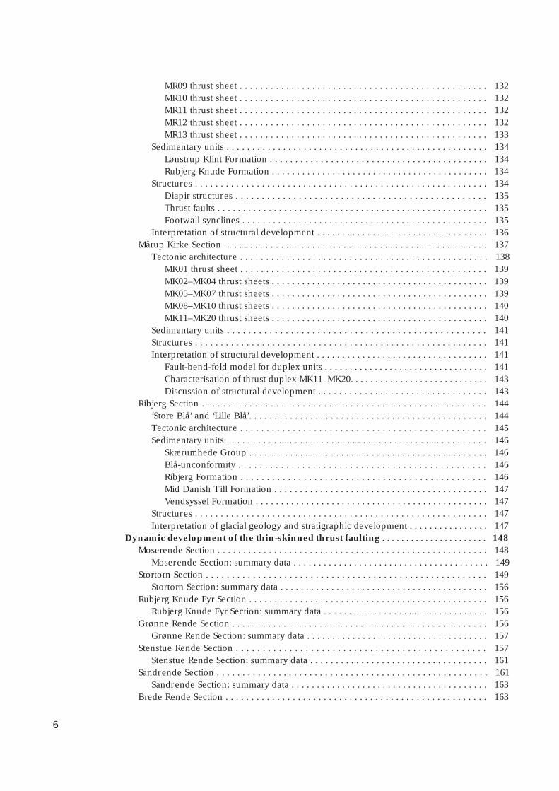
Diamictite
Glaciolacustrine andglaciofluvial sand and gravel
Mobilised mud
Non-marine sand
Non-marine clay and silt
Marine clay
Rubjerg Knude Formation
Lønstrup Klint Formation
Stortorn Formation
0 500 1000 1500 2000 2500 3000
0 100 200 300 400 5
150014001300120011001000
2000 2100 2200 2300 2400 2500
350034003300320031003000
4100 4200 4300 4400 4500
560055005400530052005100
steps
Ribjerg
Moserende
Kramrende
Stenstue Rende
Stortorn
Grønne Rende
Brede Rende
Stensnæs
Fig. 2. Geological cross-section of the Rubjerg KnudeGlaciotectonic Complex. For details and legend, see Plate 1.

13
l l l l l l
l l l l l l
l l l l l
l l l l l
l l l l l l
l l l l l l
l l l l
Aeolian dunes
Holocene peat
Marine clay and sand
Sandy till
Glaciofluvial sand
{ Mid Danish Till Formation &Kattegat Till Formation
Vendsyssel Formation
Ribjerg Formation
Top of dunes
Clifftop – glacial abrasion surface
Thrust, fault
Unconformity
Intraformational bedding
3500 4000 4500 5000 5500 6000 m
500 600 700 800 900 1000 m
2000 m1900180017001600
2600 2700 2800 2900 3000 m
4100 m40003900380037003600
4600 4700 4800 4900 5000 5100 m
6000 m590058005700
steps
Rubjerg Knude Fyr
Sandrende
Martørv BakkerOddervej
Ulstrup Ulstrup Rende Tvonnet Rende
Mårup Kirke
14
up to 1990, techniques of geological mapping andconstruction of geological cross-sections based on multi-model photogrammetric analysis were developed andmade available at DTU (Dueholm 1992). Initial inves-tigations in co-operation with K. Dueholm (DTU) andA.K. Pedersen (GM) proved the applicability of multi-model photogrammetry in the study of glaciotectoniccross-sections in Denmark by an examination of theMøns Klint clif f section (Pedersen 2000). Subsequent-ly, the photogrammetric investigation of the RubjergKnude clif f section was initiated, and forms the basisof the present work.
ObjectivesThe objectives of the study of the Rubjerg Knude Gla-ciotectonic Complex can be summarised as follows.
1. A description of an exceptionally well-exposed gla-ciotectonic complex, which can be taken as an ex-ample of a very low friction thrust-fault wedge, pre-sented as a detailed cross-section based on multi-model photogrammetric measurements of the Ru-bjerg Knude clif f section.
2. A demonstration of the techniques of balancedcross-section construction that permit interpretationof the unexposed parts of the thrust-fault complex.
3. The construction of a model for the dynamic de-velopment of the proglacial thrust system that dem-onstrates the sequential evolution of increasing de-formation intensity and the interplay with syntec-tonic depositional processes.
4. An interpretation of deformation processes withinthe framework of Danish glacial stratigraphy in thelate Pleistocene (late Middle to Late Weichselian c.30 000 – 20 000 years B.P.).
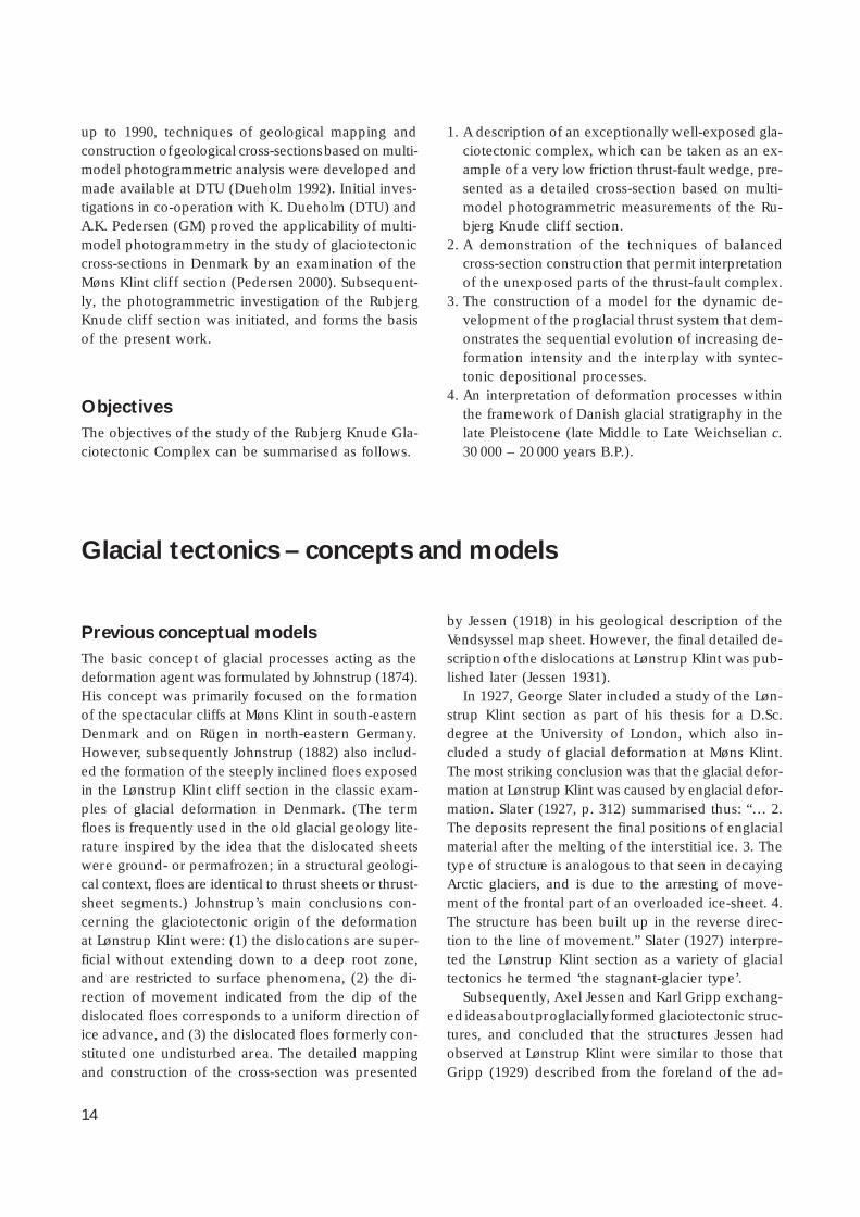
Previous conceptual modelsThe basic concept of glacial processes acting as thedeformation agent was formulated by Johnstrup (1874).His concept was primarily focused on the formationof the spectacular cliffs at Møns Klint in south-easternDenmark and on Rügen in north-eastern Germany.However, subsequently Johnstrup (1882) also includ-ed the formation of the steeply inclined floes exposedin the Lønstrup Klint clif f section in the classic exam-ples of glacial deformation in Denmark. (The termfloes is frequently used in the old glacial geology lite-rature inspired by the idea that the dislocated sheetswere ground- or permafrozen; in a structural geologi-cal context, floes are identical to thrust sheets or thrust-sheet segments.) Johnstrup’s main conclusions con-cerning the glaciotectonic origin of the deformationat Lønstrup Klint were: (1) the dislocations are super-ficial without extending down to a deep root zone,and are restricted to surface phenomena, (2) the di-rection of movement indicated from the dip of thedislocated floes corresponds to a uniform direction ofice advance, and (3) the dislocated floes formerly con-stituted one undisturbed area. The detailed mappingand construction of the cross-section was presented
by Jessen (1918) in his geological description of theVendsyssel map sheet. However, the final detailed de-scription of the dislocations at Lønstrup Klint was pub-lished later (Jessen 1931).
In 1927, George Slater included a study of the Løn-strup Klint section as part of his thesis for a D.Sc.degree at the University of London, which also in-cluded a study of glacial deformation at Møns Klint.The most striking conclusion was that the glacial defor-mation at Lønstrup Klint was caused by englacial defor-mation. Slater (1927, p. 312) summarised thus: “… 2.The deposits represent the final positions of englacialmaterial after the melting of the interstitial ice. 3. Thetype of structure is analogous to that seen in decayingArctic glaciers, and is due to the arresting of move-ment of the frontal part of an overloaded ice-sheet. 4.The structure has been built up in the reverse direc-tion to the line of movement.” Slater (1927) interpre-ted the Lønstrup Klint section as a variety of glacialtectonics he termed ‘the stagnant-glacier type’.
Subsequently, Axel Jessen and Karl Gripp exchang-ed ideas about proglacially formed glaciotectonic struc-tures, and concluded that the structures Jessen hadobserved at Lønstrup Klint were similar to those thatGripp (1929) described from the foreland of the ad-
Glacial tectonics – concepts and models
15
vancing Holmströms Gletscher on Spitsbergen. In hisdetailed and comprehensive description of his inves-tigations, Jessen (1931) concluded that the disloctionscannot have formed englacially, but must be the resultof pressure building up due to loading at the marginof the advancing ice. This pressure spreads out later-ally into the clayey units, which in the foreland reactby splitting up into fractured dislocation sheets com-pressed in front of the advancing ice masses.
Jessen (1931) also discussed the dif ficulty relatedto the displacement of the sheets without fracturingof the lithological units resulting in a complete col-lapse during deformation, and he pointed out thatJohnstrup (1882) had suggested that the deformedlayers could have been ground-frozen. Jessen’s (1931)more subjective arguments against Slater’s work con-cern the fact that Slater (1927) did not refer to Jessen’s(1918) substantial work on Vendsyssel and in particu-lar his published cross-section of Lønstrup Klint. Jes-sen pointed out that major anticlines in Slater’s cross-section between Mårup Kirke and Rubjerg Knude Fyrdo not exist, and that Slater’s (1927) misinterpretationmust be ascribed to his superficial investigations whichdid not allow him to check the way-up relationship ofeach limb in the fold structure (Jessen 1931).
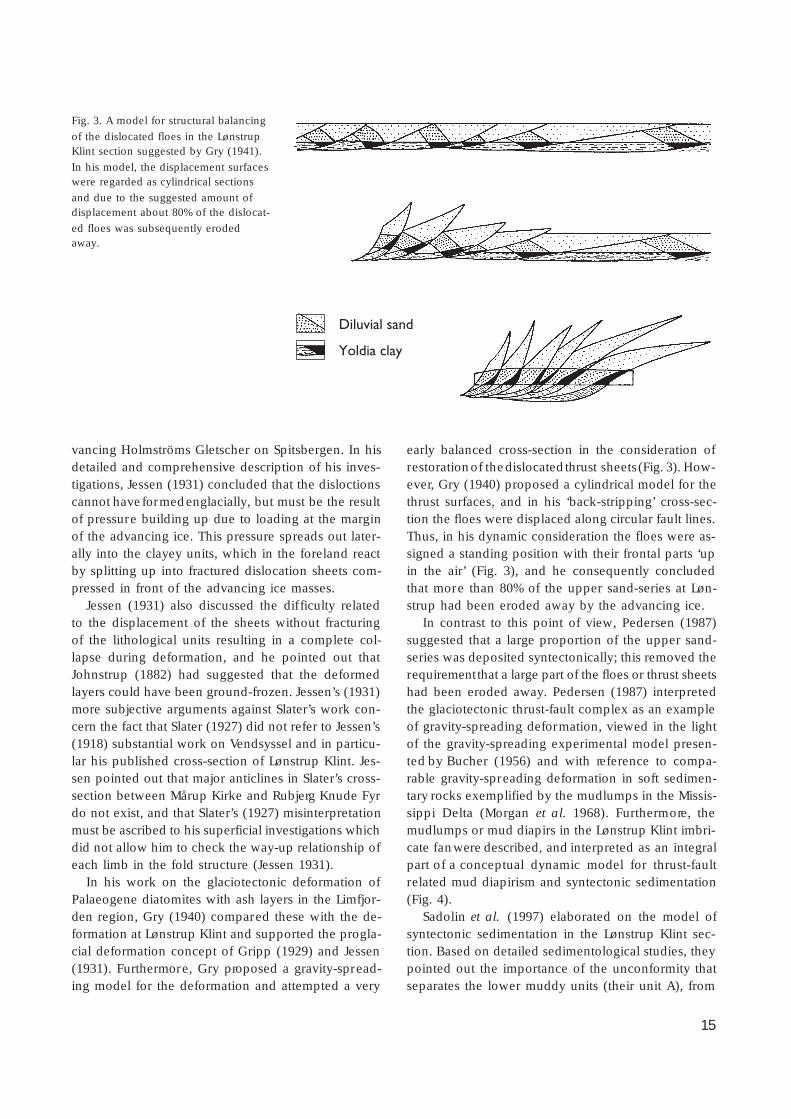
In his work on the glaciotectonic deformation ofPalaeogene diatomites with ash layers in the Limfjor-den region, Gry (1940) compared these with the de-formation at Lønstrup Klint and supported the progla-cial deformation concept of Gripp (1929) and Jessen(1931). Furthermore, Gry proposed a gravity-spread-ing model for the deformation and attempted a very
early balanced cross-section in the consideration ofrestoration of the dislocated thrust sheets (Fig. 3). How-ever, Gry (1940) proposed a cylindrical model for thethrust surfaces, and in his ‘back-stripping’ cross-sec-tion the floes were displaced along circular fault lines.Thus, in his dynamic consideration the floes were as-signed a standing position with their frontal parts ‘upin the air’ (Fig. 3), and he consequently concludedthat more than 80% of the upper sand-series at Løn-strup had been eroded away by the advancing ice.
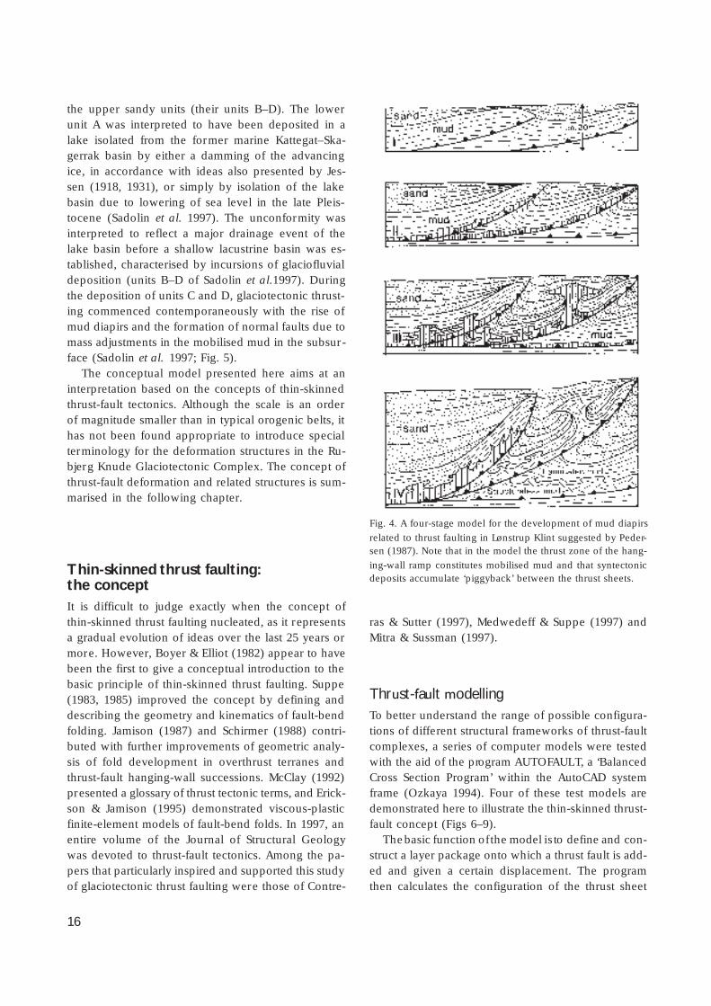
In contrast to this point of view, Pedersen (1987)suggested that a large proportion of the upper sand-series was deposited syntectonically; this removed therequirement that a large part of the floes or thrust sheetshad been eroded away. Pedersen (1987) interpretedthe glaciotectonic thrust-fault complex as an exampleof gravity-spreading deformation, viewed in the lightof the gravity-spreading experimental model presen-ted by Bucher (1956) and with reference to compa-rable gravity-spreading deformation in soft sedimen-tary rocks exemplified by the mudlumps in the Missis-sippi Delta (Morgan et al. 1968). Furthermore, themudlumps or mud diapirs in the Lønstrup Klint imbri-cate fan were described, and interpreted as an integralpart of a conceptual dynamic model for thrust-faultrelated mud diapirism and syntectonic sedimentation(Fig. 4).
Sadolin et al. (1997) elaborated on the model ofsyntectonic sedimentation in the Lønstrup Klint sec-tion. Based on detailed sedimentological studies, theypointed out the importance of the unconformity thatseparates the lower muddy units (their unit A), from
Diluvial sand
Yoldia clay
Fig. 3. A model for structural balancing
of the dislocated floes in the LønstrupKlint section suggested by Gry (1941).
In his model, the displacement surfaceswere regarded as cylindrical sections
and due to the suggested amount ofdisplacement about 80% of the dislocat-
ed floes was subsequently erodedaway.
16
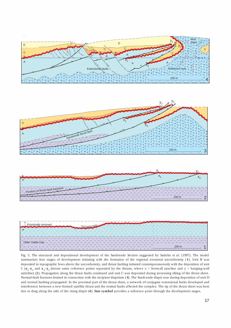
the upper sandy units (their units B–D). The lowerunit A was interpreted to have been deposited in alake isolated from the former marine Kattegat–Ska-gerrak basin by either a damming of the advancingice, in accordance with ideas also presented by Jes-sen (1918, 1931), or simply by isolation of the lakebasin due to lowering of sea level in the late Pleis-tocene (Sadolin et al. 1997). The unconformity wasinterpreted to reflect a major drainage event of thelake basin before a shallow lacustrine basin was es-tablished, characterised by incursions of glaciofluvialdeposition (units B–D of Sadolin et al.1997). Duringthe deposition of units C and D, glaciotectonic thrust-ing commenced contemporaneously with the rise ofmud diapirs and the formation of normal faults due tomass adjustments in the mobilised mud in the subsur-face (Sadolin et al. 1997; Fig. 5).
The conceptual model presented here aims at aninterpretation based on the concepts of thin-skinnedthrust-fault tectonics. Although the scale is an orderof magnitude smaller than in typical orogenic belts, ithas not been found appropriate to introduce specialterminology for the deformation structures in the Ru-bjerg Knude Glaciotectonic Complex. The concept ofthrust-fault deformation and related structures is sum-marised in the following chapter.
Thin-skinned thrust faulting:the conceptIt is difficult to judge exactly when the concept ofthin-skinned thrust faulting nucleated, as it representsa gradual evolution of ideas over the last 25 years ormore. However, Boyer & Elliot (1982) appear to havebeen the first to give a conceptual introduction to thebasic principle of thin-skinned thrust faulting. Suppe(1983, 1985) improved the concept by defining anddescribing the geometry and kinematics of fault-bendfolding. Jamison (1987) and Schirmer (1988) contri-buted with further improvements of geometric analy-sis of fold development in overthrust terranes andthrust-fault hanging-wall successions. McClay (1992)presented a glossary of thrust tectonic terms, and Erick-son & Jamison (1995) demonstrated viscous-plasticfinite-element models of fault-bend folds. In 1997, anentire volume of the Journal of Structural Geologywas devoted to thrust-fault tectonics. Among the pa-pers that particularly inspired and supported this studyof glaciotectonic thrust faulting were those of Contre-
ras & Sutter (1997), Medwedeff & Suppe (1997) andMitra & Sussman (1997).
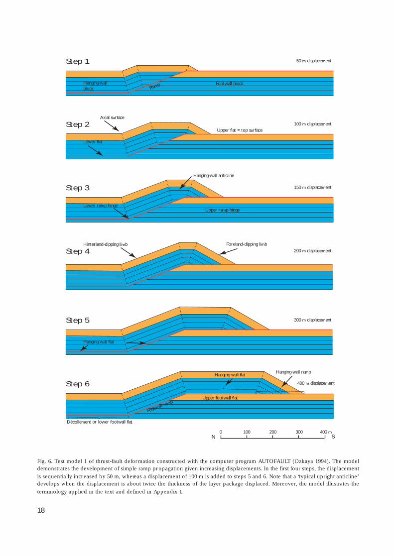
Thrust-fault modellingTo better understand the range of possible configura-tions of different structural frameworks of thrust-faultcomplexes, a series of computer models were testedwith the aid of the program AUTOFAULT, a ‘BalancedCross Section Program’ within the AutoCAD systemframe (Ozkaya 1994). Four of these test models aredemonstrated here to illustrate the thin-skinned thrust-fault concept (Figs 6–9).
The basic function of the model is to define and con-struct a layer package onto which a thrust fault is add-ed and given a certain displacement. The programthen calculates the configuration of the thrust sheet
Fig. 4. A four-stage model for the development of mud diapirs
related to thrust faulting in Lønstrup Klint suggested by Peder-sen (1987). Note that in the model the thrust zone of the hang-
ing-wall ramp constitutes mobilised mud and that syntectonicdeposits accumulate ‘piggyback’ between the thrust sheets.
17
100 m
100 m
100 m
100 m
Sandrende thrust fault
C
C
C B
B
B
B A
A
A
A
A
B
C
A
Muddiapir
x1A x2
A
CC
Mobilized mud
y1
y2
Extensional faults
Mobilized mud
x1
x2
y1y2
x1 x2
y1 y2
Position of thrust-fault fractures
UnconformityErosionally removed
2
1
DD
m. s. l.
Older Yoldia Clay
4
3
Fig. 5. The structural and depositional development of the Sandrende Section suggested by Sadolin et al. (1997). The modelsummarises four stages of development initiating with the formation of the regional erosional unconformity (1). Unit B was
deposited in topographic lows above the unconformity, and thrust faulting initiated contemporaneously with the deposition of unitC (x
1–y
1 and x
2–y
2 denote same reference points separated by the thrusts, where x = footwall syncline and y = hanging-wall
anticline) (2). Propagation along the thrust faults continued and unit C was deposited during increasing tilting of the thrust sheet.Normal-fault fractures formed in connection with the incipient diapirism (3). The Sandrende diapir rose during deposition of unit D
and normal faulting propagated. In the proximal part of the thrust sheet, a network of conjugate extensional faults developed andinterference between a new-formed satellite thrust and the normal faults af fected the complex. The tip of the thrust sheet was bent
due to drag along the side of the rising diapir (4). Star symbol provides a reference point through the development stages.
18
Step 1
Step 2
Step 3
Step 4
Step 5
Step 6
Hanging-wallblock Ramp Footwall block
50 m displacement
100 m displacement
150 m displacement
200 m displacement
300 m displacement
400 m displacement
Lower flat
Axial surface
Upper flat = top surface
Lower ramp hingeUpper ramp hinge
Hanging-wall anticline
Hinterland-dipping limb Foreland-dipping limb
Hanging-wall flat
Hanging-wall flatHanging-wall ramp
Upper footwall flat
Footwall ramp
Décollement or lower footwall flat
0 100 200 300 400 mN S
Fig. 6. Test model 1 of thrust-fault deformation constructed with the computer program AUTOFAULT (Ozkaya 1994). The modeldemonstrates the development of simple ramp propagation given increasing displacements. In the first four steps, the displacement
is sequentially increased by 50 m, whereas a displacement of 100 m is added to steps 5 and 6. Note that a ‘typical upright anticline’develops when the displacement is about twice the thickness of the layer package displaced. Moreover, the model illustrates the
terminology applied in the text and defined in Appendix 1.
19
for the specific model constructed. Thus the programgives the ‘differential’ calculation model to an induced‘integration’ solution configuration. Further thrust faultscan be added, and be given new displacements, suchthat rather complex models can be constructed. How-ever, a few limitations of the program hamper realisticcomparisons with nature. Thus the program cannothandle inclinations exceeding 60°. In general this isnot a problem as ramp angles typically range between10° and 35° and for rock mechanical reasons neverexceed 45° (Ozkaya 1994). However, the problem ofsteep inclinations becomes important in complexesincluding superimposed deformation. A second limi-tation is that testing with superimposed displacementsrequires a construction with an upper flat located with-in the model. This results in an unrealistically highnumber of shallow upper flats in the models, as illus-trated below in test model 4 (see Fig. 9). Thirdly, theprogram cannot accommodate cross-cutting thrust-faultrelationships, which limits the spacing and dip oframps. Nevertheless, the test models give a good in-troduction to the thrust-fault concept, and demonstra-tion of models with basic layer package dimensionsapproaching the scale of thrust sheets involved in theRubjerg Knude Glaciotectonic Complex can be achie-ved.
A glossary of the thrust-fault terms used here isgiven in Appendix 1; note that only contractionalthrust-fault structures are considered.
Test model 1
The first AUTOFAULT model displays a simple thrustfault with one ramp connecting a lower and an upperflat (Fig. 6). The development of thrust-fault structures,in particular the fault-bend folding of the hanging-wall anticline, is demonstrated in six steps with increas-ing displacement. The ramp angle is 25°, and the layerpackage constitutes a lower unit 25 m thick where thelower flat (or the décollement zone) is located. Abovethis, one 25 m and two 20 m thick layers have beenconstructed, with a 30 m thick uppermost layer (Fig.6). The model approaches the assumptions of parallelbehaviour with preservation of layer thickness, no netdistortion where layers are horizontal, and conserva-tion of bed length (Suppe 1983).
Step 1 shows the gentle hanging-wall anticlinal fold-ing after 50 m displacement. Note the flat-topped na-ture of the hanging-wall anticline, which makes it al-most insignificant. The backlimb of the anticline dips
toward the left, parallel to the ramp, and the axialsurfaces defined by the bend above the lower ramphinge and the bend of the hanging-wall anticline de-fine two kink bands dipping steeply to the right. Bycomparing steps 1 and 2 it can be seen that the spac-ing between the kink bands increases with increasingdisplacement.
Step 2 gives the configuration after 100 m displace-ment. Here the forelimb dipping towards the forelandto the right starts to be a significant part of the struc-ture. Note the increase in spacing between the kinkbands in the backlimb structure. The kink bands de-fine minor zones of weakness, which could developinto small reverse faults as in the thrust model dem-onstrated by Wiltschko (1979). These are referred toas back thrusts.
Step 3 shows the structural development after 150m displacement. Note that the flat-topped hanging-wall anticline now has a more angular upright form,where the kink bands fanning up from the positionsnear the upper ramp hinge approach each other. How-ever, in the model the anticline maintains its flat-toppedstructure and retains two axial surfaces (kink bands).
Step 4 demonstrates the formation of the upright,angular hanging-wall anticline, where the amount ofdisplacement is close to the length of the thrust-faultramp. Due to the geometric adjustments the hanging-wall ramp is shorter than the footwall ramp. The dis-placement is 200 m corresponding to about two timesthe thickness of the thrust sheet.
Step 5 shows the structural development after 300m displacement. The hanging-wall anticline becomeseven more flat-topped and the space between its axialsurface kink bands increases. Note that the foreland-dipping forelimb is linked to the hanging-wall rampdisplaced along the footwall flat, and the hinterland-dipping backlimb corresponds to the hanging-wall flatbent up along the footwall ramp.
Step 6, with a displacement of 400 m demonstratesthat the main structural configuration is maintained,except for the increase in spacing between the back-limb and the forelimb.
Test model 2
The second AUTOFAULT model demonstrates thepropagation along a thrust fault dif ferentiated into adécollement zone, a lower ramp, an intermediate flat,an upper ramp and an upper flat bringing the thrustfault up to the top surface (Fig. 7). The model is con-

20
structed with two lower units, 40 m in thickness; thedécollement zone is located in the second layer. Thelower layers mimic the lower clay units of the Løn-strup Klint stratigraphy, and two c. 25 m thick layersoverlie them. The top layer is 50 m thick, but whilenot comparable to any part of the stratigraphy in theLønstrup Klint section, its construction yields a betterdemonstration of the development envisaged. Thelower ramp is given a dip of 25° and the upper rampa dip of only 15° to reflect the principle of increasingangle of fracturing with increasing depth (Hobbs etal. 1976; Pedersen 1996). The distance between lowerand upper ramps along the intermediate flat is c. 250m, and three steps are presented in Fig. 7.
Step 1 is given 50 m displacement and two hang-ing-wall anticlines immediately appear. The steep rampclearly initiates the formation of an upright anticlinewith steeply dipping limbs. Between the two hang-ing-wall anticlines, an intervening syncline forms above
the intermediate flat. The involute surface of the syn-cline provides the location for a broad, shallow basin.
Step 2 shows the structural development after 100m displacement. This demonstrates clearly that theintervening syncline is an obvious site for a piggy-back basin to develop. Note that the steeply dippingforelimb of the hanging-wall anticline above the lowerramp would be the obvious site for erosion and thesource of material feeding into the piggyback basin.
Step 3 demonstrates that with a displacement of 200m, the piggyback basin becomes narrow and is ele-vated to a higher position as a consequence of thedisplacement up along the upper ramp; it is eventual-ly lifted out of the position for being a centre of depo-sition. With increasing displacement, the frontal part ofthe thrust sheet develops into a wedge-shape structure.
Hanging-wallblock
Lower hanging-wall ramp
Lower ramp
Upper ramp
Upper flat
Upper hanging-wall ramp
Upper hanging-wall ramp
Footwall block
50 m displacement
100 m displacement
200 m displacement
Piggyback basin
Piggyback basin
Intermediate flat
Lower flat
Fault-bend folding
Step 1
Step 2
Step 3
0 100 200 mN S
Fig. 7. Test model 2 of thrust-fault deformation constructed with the computer program AUTOFAULT. The model demonstrates thedevelopment of thrust-fault propagation along a lower and an upper ramp and the connecting flats. Note in this model the
formation of two anticlines divided by a syncline, the depression of which is the obvious location of a piggyback basin.

21
Test model 3
The third AUTOFAULT model aims at constructing animbricate complex by branching faults fanning up fromthe same décollement level (Fig. 8). The model is con-structed with a lower 20 m thick unit in the top ofwhich the décollement zone is located. Above the dé-collement zone, three units with a combined thick-ness of 50 m form the lower part of the thrust sheets,and the succession is capped by an upper 20 m thickunit. In three sequential steps, the principle of piggy-back thrusting is demonstrated (Fig. 8).
Step 1 shows 100 m displacement along a deep-rooted ramp dipping 30°. Note the normal architec-ture of the hanging-wall anticline results from theramping (compare with Fig. 6, step 3).
Step 2 demonstrates the re-orientation of the piggy-back thrust sheet by the introduction of 100 m displace-ment along a 18° dipping ramp in front of and belowthe first thrust fault. Note that the accumulated dis-
placement of the first thrust sheet amounts to c. 200 m.Step 3 shows an additional 100 m displacement along
a low-angle 12° dipping ramp. Although the modeldemonstrates the main architecture of the imbricatefan illustrated by Pedersen (1987), it is a fairly simplemodel which may have only little relevance to naturalconditions.
Test model 4
The final AUTOFAULT model demonstrates the morelikely formation of a steeply dipping imbricate fan orduplex (Fig. 9). The model is given the same strati-graphic units as in Test Model 3 (Fig. 8). A longer dé-collement zone is located in the middle of the lower-most unit, in addition to an intermediate flat in thethird layer, while the upper flats are located withinthe uppermost unit. The initial steps in the construc-
1
1 2 3
1 2
100 m displacement
100 + 100 m displacement
300 m accumulated displacement
Simple ramp
Piggyback thrust sheet
Branching thrust fault
Branching thrust-fault imbricate fan
Step 1
Step 2
Step 3
0 100 200 mN S
Fig. 8. Test model 3 of thrust-fault deformation constructed with the computer program AUTOFAULT. The model demonstrates the
formation of an imbricate fan by successive thrust-fault splays branching up from the main décollement zone. The encirclednumbers refer to the sequential phase of thrust imbrication. The model is probably not comparable to structures formed in nature,
but can be regarded as an introduction to test model 4 (Fig. 9).

22
tion of this model are similar to the examples demon-strated above, and hence only the final two steps areillustrated (Fig. 9). However, these give a convincingillustration of the increase of dips in an imbricate thrust-fault complex.
Step 1 illustrates the final structural architecture af-ter 140 m displacement of thrust sheet 1 along thedécollement zone, the lower ramp, the intermediateflat, an upper ramp and onto the upper flat (dips oframps c. 25°). Thrust sheets 2–5 were formed by branch-ing ramps (dip of ramps c. 15°) with a displacementof c. 80 m added to each thrust fault. Finally, the lead-ing thrust sheet (6) is displaced 90 m along the lowerdécollement zone and a deep-rooted 30° dipping ramp.Note that the branching ramp imbricates are carriedpiggyback on thrust sheet 6. Furthermore, it shouldbe noted that a long trailing segment of thrust sheet 6occurs between the décollement zone and the inter-mediate flat. If this trailing segment becomes choppedup into duplexes between the two deep-rooted ramps,it will affect the overlying imbricates by vertical eleva-tion and the formation of antiformal stacks.
Step 2 illustrates the over-steepening of the imbri-cates stacked onto the backlimb of the hanging-wallanticline of thrust sheet 6 arising from the addition of100 m displacement to step 1 along the leading thrustrooting down to the lower décollement zone.
Test models: concluding remarks
A set of principles may be derived from the test models.
1. The level of elevation of the reference surface isdirectly related to the number and sizes of rampsthe thrust sheet has passed. A ramp rooting downto a deep flat level corresponds to a high elevationof the topmost reference surface. In contrast, if a topreference surface is positioned at the same level asin the foreland, the thrusting corresponds to a trans-lation along a flat.
2. The steeper the ramp, the earlier its time of forma-tion. Gently dipping ramps are initiated at a late stageof deformation in areas proximal to the foreland.
3. The thickness of a piggyback basin reflects its du-ration as depocentre. Thus a small thickness of pig-gyback basin fill indicates an early trapping of thebasin by overthrusting of a hanging-wall block.
4. A thick succession in the piggyback basin reflects along period of translation of the thrust sheet alonga long flat.
Step 1
Step 2
Fig. 9. Test model 4 of thrust-
fault deformation constructedwith the computer program
AUTOFAULT. The modeldemonstrates an imbricate fan
(see Fig. 8) subjected to fault-bend folding during piggyback
translation of an underlyinghanging-wall flat propagation
along a footwall ramp. Thefootwall ramp propagation will
consequently result in increasingdips of the thrust sheets in the
imbricate fan. Encirclednumbers indicate successive
thrust sheets.
Concept of balanced cross-sectionThe principle of the balanced cross-section in struc-tural analysis of thrust-fault systems was elegantlyoutlined by Dahlström (1969) and further improvedby Suppe (1985). The application of balanced cross-sections in glaciotectonics has been demonstrated byCroot (1987), Klint & Pedersen (1995) and Pedersen(1996).
In the construction of the balanced section, twodifferent functions are applied: (1) the line balance,and (2) the volume balance, which in a 2-D cross-section corresponds to area balance. The first func-tion concerns the length of displacement, whereas thesecond function concerns the preservation of volumein the deformed cross-section compared with the re-stored undeformed cross-section (for demonstrationsee Plate 2). The basic method of balancing a cross-section (Dahlström 1969) is restoration by defining apinpoint to be fixed to the foreland and then restor-ing the thrust sheets back to their initial pre-deforma-tional position. Thus one begins at the foreland andthen by line balancing the thrust sheets are pulledback sequentially to their position prior to displace-ment. This requires a measure of displacement, whichis the essential, but often difficult figure to achievewithout some range of uncertainty.
Details concerning the construction of the balancedcross-section of the Rubjerg Knude Glaciotectonic Com-plex (Plate 2) are given below.

23
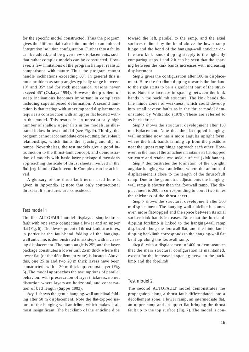
LocationThe Rubjerg Knude cross-section is 6124 m long andextends from the coastal cliff immediately south ofLønstrup, Ribjerg, to about 300 m north of the rampleading down to the beach at Nørre Lyngby (Fig. 2,Plate 1). The strike of the section is 17°, which is nearlyparallel to the direction of the coastline. This is alsoapproximately perpendicular to the main concentra-tion of structural strikes (bedding, thrust faults and foldaxes; Fig. 10). The cross-section was consequentlyconstructed to fit a general plane of orthographic pro-jection with a projection axis striking 107°.
The Rubjerg Knude cross-section covers only theRubjerg Knude Glaciotectonic Complex. Thus it is notas extensive as the cross-section of Lønstrup Klint con-structed by Jessen (1918, 1931), which extends fromthe cliff at the northern fringe of Lønstrup to the north-ern part of the beach at Løkken (see Fig. 12). TheUTM co-ordinates (zone 32, ED50) of the end pointsof the Rubjerg Knude cross-section are 547512, 6370243(N-end point) and 545251, 6364783 (S-end point).
Photogrammetric workThe cross-section of Rubjerg Knude GlaciotectonicComplex (Plate 1) is based on a multi-model photo-grammetric investigation of the cliff section using themethod described by Dueholm (1992). Oblique pho-tographs were taken from a Cessna fixed-wing air-craft with a Minolta XG2 camera with known opticalspecifications, calibrated at the laboratory of photo-grammetry at the Technical University of Denmark.Standard 24 × 36 mm diapositive colour film was used,and the photographs were taken with 66% overlapfrom a distance of 200–300 m with an inclination an-gle of c. 35°, which provided the basis for setting up67 stereoscopic models. In the laboratory, the orien-tation of the stereo-models was carried out based onground control points adapted from two sets of verti-cal aerial photographs at a scale of 1:25 000, namelyD9202 G 1365–66 and KMS 9203 A509–10 taken inMay 1992.
The stereoscopic instrument used was a Kern DSR15 analytic plotter with a DEC VMS operating systemand the special attached GEOPROGRAM developed
N S0 100 200 m
100 m displacementon youngest thrust fault
200 m displacementon youngest thrust fault
1
1
2 3 5
2 3 4
5
4 6
6
Location and construction of the Rubjerg Knudecross-section
24
1
2
3
N
n = 52
1
2
3
n = 60
N
1
2
3
n = 83
N
1
2
3
n = 83
NA B
C D
Fig. 10. Stereographic projection diagrams of the orientation of structural elements in the Rubjerg Knude cross-section. The stereo-
grams, lower hemisphere, equal area (Schmidt) net, display the concentration of the poles to bedding planes (black dots) or thrustplanes (black triangles). A and B are measurements taken from Jessen (1931), and C and D are data produced in this study. Contour
intervals are 1, 2.5, 5, 7.5, 10, 12.5, and 15%. The density point in all four diagrams is close to 197°/35°. Comparing the two sets ofdiagrams demonstrates that the structural orientation has been maintained despite c. 100 years erosion corresponding to c. 125 m
retreat of the coastal cliff section. Black squares (D) indicate normal fault planes. Blue lines/numbers indicate principal compres-sion axes.
25
by Dueholm (1992). In the stereoscopic models, thegeological features were outlined by the floating markand digitised by the attached computer. The digitiseddata were stored for the later construction of the cross-section and the transformation for other programsapplied for the management of the cross-section dis-play. The scale of the Rubjerg Knude cross-section inthe analytic plotter version is 1:500, and the accuracyof the plotted data is about 25 cm (for further details,see Appendix 2).
Digital editingIn order to represent the cross-section in a publish-able display, the digitised data were transferred to ARC-INFO at the GIS-laboratory at the Geological Survey.Here it was transformed into an ARC-VIEW project,which served as the computer tool for editing the cross-section. Thus all areas were converted to closed poly-gons, which were annotated to fit the legend of litho-logies. During this editing, interpretations were made
to finish the display of the cross-section, in particularinterpretations of the scree-covered parts of the sec-tion. This was carried out contemporaneously with theconstruction of the balanced cross-section (see be-low), and a few additional corrections were added tothe Rubjerg Knude cross-section. Some new exposuresalong the cliff section appeared in 1997–1999, whichadded to a better understanding of the structures inthe transition from the frontal part of the glaciotec-tonic complex to its foreland. These have been incor-porated into the ARC-VIEW project.
The final editing of the cross-section concerned thebalanced cross-section. The construction of the bal-anced section was digitised and transformed into anARC-VIEW project, and the subsequent interpretationof the extension of the thrust-fault ramps below sealevel was added. Thus the Rubjerg Knude cross-sec-tion comprises a display of the exposed part of the cliffsection with lithological and structural identity addedas themes. Furthermore, the cross-section includes aninterpretation of the thrust-fault structures in the sub-surface. Finally, a balanced construction was added
l l2900 3000 m
Dc
Dm
Ds
α
αL/R-u
L/R-u
T
T TT
L/R-u L/R-u
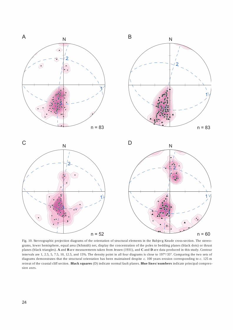
Fig. 11. Illustration of the method used for estimation of the displacement for the balanced cross-section. Above the main erosional
unconformity at the top of the cliff, the extension of the thrust sheet tip is constructed by the intersection between the thrust fault(T) and the L/R-unconformity (L/R-u) based on the angle (±) between the bedding of the thrust sheet and the hanging-wall ramp.
Dm, displacement measured; Dc, displacement constructed from tip-extension; Ds , displacement estimated from the interpretationof thrust-fault trace under the scree cover. The section illustrated is part of the Rubjerg Knude Fyr Section (Plate 1).

26
Table 1. The distribution of areas in the balanced cross-section (Plate 2)
Balance (Plate 2A) Ramps (Plate 2B)
Section* Numberof areas
Area (m2) Section* Numberof areas
Area (m2)
01UL 5 23 048 01UL 13 24 302
02SN 13 8965 02SN 18 8536
03MB 15 28 443 03MB 21 30 944
04KR 10 24 158 04KR 22 18 390
05BR 28 34 143 05BR 40 33 548
06SR 28 33 218 06SR 49 31 588
07SS 32 26 421 07SS 31 23 973
08GR 55 49 842 08GR 47 45 118
09RF 30 22 827 09RF 26 21 458
10ST 54 43 674 10ST 41 36 656
11MR 69 51 902 11MR 55 45 342
12MK 95 82 226 12MK 87 62 763
13BL 8 17 922 13BL 2 14 313
NrLy 2 5437 13RI 1 4405
PTR 3 2538 MD 1 472
Ve 4 9818
* The annotated numbers of sections (05BR) correspond to the sequential location of each section in a distal–proximal order, and the capitalised letters refer to the general abbreviation of the section names (see Plate 2).
to the cross-section project, such that each thrust sheetis annotated in a balanced restored cross-section aswell as in the structural cross-section displaying thegeometry of the ramps and flats (Plate 2).
Construction of the balancedcross-sectionThe construction of the balanced cross-section for theRubjerg Knude Glaciotectonic Complex was based onthe geological cross-section, which displays the geo-metry of the thrust sheets in sufficient detail to allowcalculations of their displacements and cross-section-al areas (Plates 1, 2). The method of balancing neces-sitates that the thrust sheet closest to the foreland isthe first to be restored to its pre-deformational posi-tion. Therefore, the balancing works backwards fromthe distal to the proximal deformation area, and con-
sequently the annotation of the thrust sheets beginswith the first thrust sheet restored. In the balancedcross-section of the Rubjerg Knude GlaciotectonicComplex, the thrust sheets are additionally annotatedaccording to that part of the cliff in which they occur:two capital letters refer to the name of the section anda number refers to its position from leading edge totrailing end of the section. Thus, KR01 is the thrustsheet nearest to the foreland in the Kramrende Sec-tion. A thrust fault is referred to according to the thrustsheet it displaces. However, the trailing footwall rampis referred to the annotation of the footwall block,which underlies the hanging-wall ramp/flat of thethrust sheet displaced over it. Thus the KR02 hang-ing-wall ramp is displaced up along the KR01 foot-wall ramp.
Although one of the basic conditions in construct-ing balanced sections is the preservation of volumes,which in the areas strongly affected by mud remobili-

27
sation and diapirism is difficult to maintain, the exer-cise has been carried out to match a balanced sectionto the mapped and interpreted thrust-fault framework.So despite the uncertainties and the demand for inter-pretation of the geometry and magnitude of erodedthrust sheet tapers, the construction of the balancedsection added significantly to the understanding of theduplex framework (Plate 2B).
In the Rubjerg Knude cross-section (Plate 1), thedisplacement is measured and estimated mainly fromthe distance between the intersection of the L/R-un-conformity (the unconformity between the LønstrupKlint and Rubjerg Knude Formations, see below) andthe footwall ramp, and the intersection of the L/R-unconformity and the hanging-wall ramp (Fig. 11). How-ever, the tips of the thrust sheets are generally erodedaway, so the first approximation is from the L/R-un-conformity footwall point to the point where the hang-ing-wall ramp is truncated by the glaciotectonic un-conformity at the top of the cliff. The second approx-imation is the addition of the distance estimated fromthe size of the tip eroded away. This estimate is basedon a simple geometric construction of the tip-triangle
from the dips of the hanging-wall ramp and the L/R-unconformity, respectively (Fig. 11). This line balanceis subsequently controlled by the width of the piggy-back basin more or less corresponding to the upperfootwall flat. All the measured displacements are strictlyrestricted to the minimum distance to avoid unrealis-tic exaggerations. Therefore the actual displacementsmight be slightly greater.
The area balance is based on a calculation of allthe areas annotated in Plate 2. The computer-supportedcalculation was carried out with the ARC-INFO pro-gram, and the calculations of the areas in the bal-anced cross-section and the ramp cross-section devi-ate by less than 10% (Plate 2A, B). This is regarded asa reasonable correspondence considering the varioussources of error (Table 1). In general, the sectionshave a smaller area in the ramp cross-section (Plate2B) due to the erosion of areas above the main head-of-cliff unconformity, and in most sections the numberof areas is higher due to the increased complexity ofthe geometry in the reconstructed structural cross-sec-tion (Plate 2B).
Geological setting
The Rubjerg Knude Glaciotectonic Complex incorpo-rates deformed sedimentary deposits that belong tothe upper part of the mainly marine succession knownpreviously as the Skærumhede series (Jessen et al.1910). This succession was deposited in the northernpart of the Danish Basin in the late Pleistocene, afterthe late Saalian terrestrial glaciation retreated from Den-mark (Houmark-Nielsen 1987, 1999; Knudsen 1994).The major source area for deposits in this part of theDanish Basin is the Scandinavian basement in south-ern Norway and central Sweden, that comprises Pre-cambrian Fennoscandian granites and gneisses over-lain by Palaeozoic metasediments, including Permianvolcanics and their related intrusive magmatic rocksof the Oslo province (Oftedahl 1981). The extrabasi-nal indicator boulders reflect these source areas, whichwere situated between the centres of ice-cap nucleationand the depositional basin (Milthers 1909; Smed 1995).
The boundary between the northern part of theDanish Basin and the south-western part of the ele-
vated Scandinavian basement is covered by the Ska-gerrak, the sea covering a deep depression (about 500m deep) known as the Norwegian Channel (Sejrup etal. 1987, 1994, 1998). One of the important discussionsconcerning the glaciation of Denmark during the laststadial focuses on how the ice from Norway advancedacross the Skagerrak about 30 000 years ago. The prob-lem involves the dynamics of the ice stream along thesouthern coast of Norway, the so-called NorwegianChannel Ice Stream, and the interaction between themarine and terrestrial parts of the ice cap in south-west Norway (Larsen et al. 2000). Associated prob-lems include the filling of the deep trench in Skager-rak, and the termination of marine conditions in Ska-gerrak, Vendsyssel, and the northern North Sea as wellas the Kattegat (for locations, see Fig. 12).
The marine environment referred to as the OlderYoldia Sea, which extended into the Vendsyssel re-gion, formed in the Late Saalian, and the climaticchange from a mild climate in the Eemian to a glacial

28
AB
58˚N
58˚N
56˚N
56˚N
SkagenHirtshals
Frederikshavn
Mols
Djursland
SamsøHven
HundestedGlumsløv
Ristinge Klint
Bovbjerg
Jylland
Jylland
Læsø
Anholt
Langeland
0 100 km50NORWAY
SWEDENLimfjorden
Skagerrak
North Sea
Skagerrak
Kattegat
Kattegat
Vendsyssel
Mors
GERMANYFig. 13
Lodbjerg
Vendsyssel
SDKT
MSL
MSL
Lim fj or d en
I I I I I I I I I I I I II
II
II
II
II
II
II
II
II
II
II
II
II
I
I I I I I I I I I I I I I I I I I I I I I I I I I I I I I I I I I
DENMARK
12˚E
12˚E
Lønstrup
Limfjorden
Jæren
N orwegia n Trench
FynSjælland
Skåne
Lønstrup Klint

29
climate in the Weichselian is recorded in a series ofwells drilled in north Jylland and the Kattegat region(Knudsen & Lykke-Andersen 1982; Lykke-Andersen1987; Lykke-Andersen & Knudsen 1991; Knudsen1994). Towards the end of the Middle Weichselian theScandinavian Ice Sheet over southern Norway built up.The ice streams were drained from a main spillway inOslo Fjord moving out through the Norwegian Chan-nel along the coastline of southern Norway (Larsen etal. 2000). A change in the dynamics of the Scandina-vian Ice Sheet over southern Norway forced the gla-ciers to progress south-westward across the Norwe-gian Channel. The ice advanced into the northernNorth Sea, where a glacial cover was established about29 000 years B.P. and lasted until 22 000 years B.P.,when the first recurrence of marine conditions (the‘Young Yoldia Sea’) was recorded (Sejrup et al. 1994,2000). This glacial coverage was probably closely con-nected with the fall in sea level, amounting to 120 mbelow present sea level (Fairbanks 1989; Bard et al .1993), which could have hampered the active drain-age of the Norwegian Channel Ice Stream. The icespread southward over the Skagerrak causing the Kat-tegat basin to be dammed by the ice margin and ter-restrial areas to be established in the central part ofthe North Sea (Sadolin et al. 1997; Houmark-Nielsen1999). As a consequence, the Kattegat–Skagerrak re-gion began to dry up due to the general sea-level fall;this is reflected in the progression from arctic marineconditions in the Skærumhede series to brackish andglaciolacustrine environments. This change took placeat about 32 000 years B.P. (Table 2), and may havebeen accentuated by the addition of meltwater fromthe advancing Norwegian Ice (Jessen 1918; Sadolin etal. 1997).
The dramatic drainage of the lake basin in the Kat-tegat towards the North Sea is recorded by a signifi-cant erosional unconformity in the sedimentary suc-cession at Lønstrup Klint (the L/R-unconformity), dat-ed as close to 29 000 years B.P. (Sadolin et al. 1997).
Shortly afterwards, the basin was once again dammedand shallow lacustrine and fluvial environments wereestablished while proglacial thrust faulting was initi-ated reflecting the relatively fast advance of the icemargin (Sadolin et al. 1997). The thin-skinned thrustfaulting in the Rubjerg Knude Glaciotectonic Com-plex involved an accretionary wedge extending morethan 12 km to the south in front of the advancing icemargin. The lowermost décollement level was situat-ed in the marine clays of the Older Yoldia Sea. After acompression of about 50%, the glaciotectonic complexwas formed (Pedersen 1987) leaving a large part ofthe area between Lønstrup and Hirtshals as a depres-sion corresponding to the ‘hole’ and the Rubjerg Knu-de Glaciotectonic Complex to the ‘hill’, in a ‘hill-and-hole’ pair in the sense of Aber et al. (1989). Subse-quently the Norwegian Ice truncated the glaciotec-tonic complex and the deposition of the Kattegat TillFormation concealed its structures. The Norwegian Iceadvanced down to a stationary line (Figs 1, 12) cross-ing central Denmark from west to east, whose posi-tion is inferred from the distribution of the KattegatTill Formation (Houmark-Nielsen 1987, 1999, 2003;Pedersen & Petersen 1997).
After its termination at the stationary line (Figs 1,12), the Norwegian Ice melted back. It was succeededby the main south-west ice advance of the Scandina-vian Ice Sheet, which extended out to the Main Sta-tionary Line (Ussing 1903; Houmark-Nielsen 1987,2003; Pedersen et al. 1988). In northern Jylland, theisostatic depression due to the loading of the ice sheetwas substantial. The termination of the glaciation inDenmark thus resulted in interference between eus-tatic sea-level rise and isostatic rebound with a com-plex depositional development during the re-estab-lishment of the Younger Yoldia Sea in the Skagerrak–Vendsyssel–Kattegat region about 17 000 years ago.This may be summarised as a forced regression underprogressively falling sea level due to the isostatic riseof the Vendsyssel region (Richard 1996). The Venne-bjerg and Rubjerg Knude hilly islands probably formedpart of a larger island archipelago extending out intothe North Sea.
Terrestrial conditions were established at the endof the Weichselian. At Nørre Lyngby (Fig. 13), a de-pression was formed above a neotectonic fault zonethat predated Older Dryas time (Lykke-Andersen 1992).In this depression, lacustrine gyttja and fluvial sand ofOlder Dryas and Allerød age were deposited; a largenumber of mammalian remains have been found inthese deposits indicating an arctic to sub-arctic rein-
Facing page:Fig. 12. Location map. Map (A) shows the main part of the
Danish Basin with the surrounding land areas. SDKT is theposition of the stationary line for the Norwegian Ice Advance
(SDKT is an abbreviation of southern distribution of KattegatTill Fm). MSL is the Main Stationary Line for the Scandinavian
Ice Sheet at the glacial maximum in the Late Weichselian.Map (B) gives the position of relevant geographical localities
in Denmark as well as the location of Fig. 13, the geologicalmap of Vendsyssel.

30
deer steppe also populated by hunters (Jessen & Nor-dmann 1915; Aaris-Sørensen 1995).
During Holocene time, the Vendsyssel region wasaffected by isostatic rebound (Mertz 1924). At Løn-strup Klint, this resulted in a 25 m elevation of theheterolithic sediments of the Younger Yoldia Sea. Bogsdeveloped in the depressions on the glacial peneplainat the end of the Stone Age and the beginning of theBronze Age (Jessen 1918). Up to 1.5 m of peat accu-mulated; when this is exposed in the clif f surface andblocks of peat fall down onto the beach, the peat islocally called martørv (sea-peat). The locality namesMartørv Bakker (sea-peat hill) and Moserende (bog-gully) refer to these deposits.
The geomorphology of the cliff is strongly influ-enced by the thrust-fault structures. The clayey partsof the thrust sheets form ridges that form projectionsalong the coast between gullies that are eroded out inthe sandy parts (Schou 1949). Springs typically wellout at the surface between the clayey and sandy unitsand more incised gullies (render in Danish) are formedwhere the drainage is concentrated. Although the lo-cation of gullies and the clif f line have retreated about100 m since A. Jessen constructed the first cross-sec-tion of Lønstrup Klint, it has been possible to retainhis names in the present cross-section (Plate 1). The
general erosion rate of the cliff is about 1.3–1.5 m peryear (Jessen 1918; Pedersen 1986b). Landslides occurvery frequently, particularly at sites where mud dia-pirs are located in the cliff section. Where glaciofluvi-al deposits dominate the cliff section, there is a markedtendency for aeolian dunes to accumulate on top ofthe cliff (Pedersen 1986b). Wind action on the mo-raine plateau on top of the cliff has eroded the fine-grained material away from the till deposits, leaving astone pavement as the residual trace of the glaciallytruncated surface.
Aeolian sand migration intensified about 300–400years ago (Jessen 1918), one of the consequences beingthe burial and abandonment of the Old Rubjerg Church.The high aeolian dunes on top of Rubjerg Knude haveaccumulated during the last 100 years. The RubjergKnude lighthouse was built in 1900 (Bendsen 1981)when dunes were less than 10 m high. Today the topsof the dunes are close to 100 m above sea level corre-sponding to a vertical dune accumulation of nearly 50m. The present-day steep nature of the dunes wasprobably stimulated by the artificial dune protectionfences. However, the steady erosion of the cliff indi-cates that the lighthouse will fall into the sea aboutten years from now.
Table 2. Radiocarbon dates, Rubjerg Knude and Lønstrup Klint, Vendsyssel, northern Denmark
Stratigraphic unit
Vendsyssel Fm
Vendsyssel Fm
Vendsyssel Fm
Rubjerg Knude Fm
Rubjerg Knude Fm
Lønstrup Klint Fm
Stortorn Fm
Stortorn Fm
Stortorn Fm
Locality
Lønstrup Klint
Lønstrup Klint
Lønstrup Klint
Sandrende
Lønstrup Klint
Sandrende
Ribjerg
Mårup Kirke
Stortorn
Lab. ID no.
K-858
K-2670
AAR-2134
AAR-2265
AAR-4066
Ua-4454
AAR-4067
AAR-4068
AAR-4069
Material
Mollusc
Mollusc
Mollusc
Plant
Mollusc
Moss
Mollusc
Mollusc
Mollusc
14C ageka B.P.
13.9 ± 0.2
14.7 ± 0.2
14.5 ± 0.2
30.9 ± 0.5
43.0 ± 1.3
29.2 ± 1.4
29.6 ± 0.4
30.9 ± 0.4
31.3 ± 0.4
Calib. ageka B.P.*
16 ± 1
17 ± 1
17 ± 1
33 ± 1
46 ± 3
32 ± 1
33 ± 1
34 ± 1
34 ± 1
13C‰PDB+
0.6
–27.3
3.3
–29.1
1.5
1.7
1.3
Ref.‡
(1)
(2)
(3)
(4)
(5)
(4)
(5)
(5)
(5)
* Calibrated ages are calculated according to Bard et al. 1993 and Kitagawa & van der Plicht (1998).+ Relative to PDB standard.‡
References: 1: Krog & Tauber (1974); 2: Knudsen (1978); 3: Richardt (1996); 4: Houmark-Nielsen et al. (1996); 5: this study.

31
Holocene
Vendsyssel Formation
Glacigene formations
Upper Cretaceous chalk
20 km5 10 150
10˚30’10˚00’
Nørre Lyngby
Mårup
Løkken
Rubjerg Knude
Skærumhede
Skagen
Frederikshavn
Hirtshals
Kattegat
Skagerrak
Location of well
Løns
trup
Klin
t Lønstrup
SandrendeVennebjerg
DGU No. 1.287
DGU No. 10.4
DGU No. 8.137
Stortorn57˚30’
DGU No. 8.137
Fig. 13. Geological map of Vendsyssel showing the location of three wells referred to in the text.

32
Hol
ocen
eM
iddl
e W
eich
selia
nLa
te W
eich
selia
n
Skæ
rum
hede
Gro
up
11.5
19–15
27–23
30–28
32–30
35–32
Form
atio
n
Unc
onfo
rmity
Lith
olog
y
Cla
y
Silt
Pebb
le
Sand
Cob
ble
Foss
ils
Stru
ctur
esan
dgr
ain
size
s
Dir
ectio
nal
elem
ents
Thi
ckne
ss
Age
ka
B.P.
(cal
enda
r ye
ars)
30
20
10
0 m
Recent aeolian dunes
Main cliff-section unconformityNr. Lyngby Beds
Vendsyssel Formation
Mid Danish TillFormation
Ribjerg Formation
Blå-unconformityeuKattegat Till
Formation
Rubjerg Knude Formation
eu L/R-unconformity
Lønstrup Klint Formation
Stortorn Formation
gu
gu
eu
eu
Clay
Silty mud
Dropstones in clay and silty mud
Sandy mud
Sand
Till
Gravel
Plant fossil dated
Shell dated
Palaeocurrent
Direction of ice movement
Erosional unconformity
Glaciotectonicunconformity
f. m. c.
eu
gu
Peat and gyttja
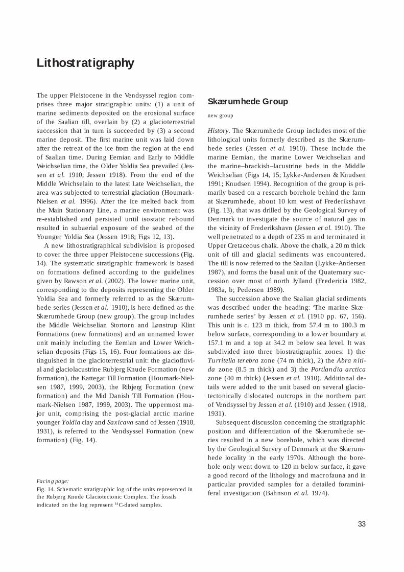
33
Lithostratigraphy
The upper Pleistocene in the Vendsyssel region com-prises three major stratigraphic units: (1) a unit ofmarine sediments deposited on the erosional surfaceof the Saalian till, overlain by (2) a glacioterrestrialsuccession that in turn is succeeded by (3) a secondmarine deposit. The first marine unit was laid downafter the retreat of the ice from the region at the endof Saalian time. During Eemian and Early to MiddleWeichselian time, the Older Yoldia Sea prevailed (Jes-sen et al. 1910; Jessen 1918). From the end of theMiddle Weichselain to the latest Late Weichselian, thearea was subjected to terrestrial glaciation (Houmark-Nielsen et al. 1996). After the ice melted back fromthe Main Stationary Line, a marine environment wasre-established and persisted until isostatic reboundresulted in subaerial exposure of the seabed of theYounger Yoldia Sea (Jessen 1918; Figs 12, 13).
A new lithostratigraphical subdivision is proposedto cover the three upper Pleistocene successions (Fig.14). The systematic stratigraphic framework is basedon formations defined according to the guidelinesgiven by Rawson et al. (2002). The lower marine unit,corresponding to the deposits representing the OlderYoldia Sea and formerly referred to as the Skærum-hede series (Jessen et al. 1910), is here defined as theSkærumhede Group (new group). The group includesthe Middle Weichselian Stortorn and Lønstrup KlintFormations (new formations) and an unnamed lowerunit mainly including the Eemian and Lower Weich-selian deposits (Figs 15, 16). Four formations are dis-tinguished in the glacioterrestrial unit: the glaciofluvi-al and glaciolacustrine Rubjerg Knude Formation (newformation), the Kattegat Till Formation (Houmark-Niel-sen 1987, 1999, 2003), the Ribjerg Formation (newformation) and the Mid Danish Till Formation (Hou-mark-Nielsen 1987, 1999, 2003). The uppermost ma-jor unit, comprising the post-glacial arctic marineyounger Yoldia clay and Saxicava sand of Jessen (1918,1931), is referred to the Vendsyssel Formation (newformation) (Fig. 14).
Skærumhede Group
new group
History. The Skærumhede Group includes most of thelithological units formerly described as the Skærum-hede series (Jessen et al. 1910). These include themarine Eemian, the marine Lower Weichselian andthe marine–brackish–lacustrine beds in the MiddleWeichselian (Figs 14, 15; Lykke-Andersen & Knudsen1991; Knudsen 1994). Recognition of the group is pri-marily based on a research borehole behind the farmat Skærumhede, about 10 km west of Frederikshavn(Fig. 13), that was drilled by the Geological Survey ofDenmark to investigate the source of natural gas inthe vicinity of Frederikshavn (Jessen et al. 1910). Thewell penetrated to a depth of 235 m and terminated inUpper Cretaceous chalk. Above the chalk, a 20 m thickunit of till and glacial sediments was encountered.The till is now referred to the Saalian (Lykke-Andersen1987), and forms the basal unit of the Quaternary suc-cession over most of north Jylland (Fredericia 1982,1983a, b; Pedersen 1989).
The succession above the Saalian glacial sedimentswas described under the heading: ‘The marine Skæ-rumhede series’ by Jessen et al. (1910 pp. 67, 156).This unit is c. 123 m thick, from 57.4 m to 180.3 mbelow surface, corresponding to a lower boundary at157.1 m and a top at 34.2 m below sea level. It wassubdivided into three biostratigraphic zones: 1) theTurritella terebra zone (74 m thick), 2) the Abra niti-da zone (8.5 m thick) and 3) the Portlandia arcticazone (40 m thick) (Jessen et al. 1910). Additional de-tails were added to the unit based on several glacio-tectonically dislocated outcrops in the northern partof Vendsyssel by Jessen et al. (1910) and Jessen (1918,1931).
Subsequent discussion concerning the stratigraphicposition and dif ferentiation of the Skærumhede se-ries resulted in a new borehole, which was directedby the Geological Survey of Denmark at the Skærum-hede locality in the early 1970s. Although the bore-hole only went down to 120 m below surface, it gavea good record of the lithology and macrofauna and inparticular provided samples for a detailed foramini-feral investigation (Bahnson et al. 1974).
Facing page:
Fig. 14. Schematic stratigraphic log of the units represented inthe Rubjerg Knude Glaciotectonic Complex. The fossils
indicated on the log represent 14C-dated samples.
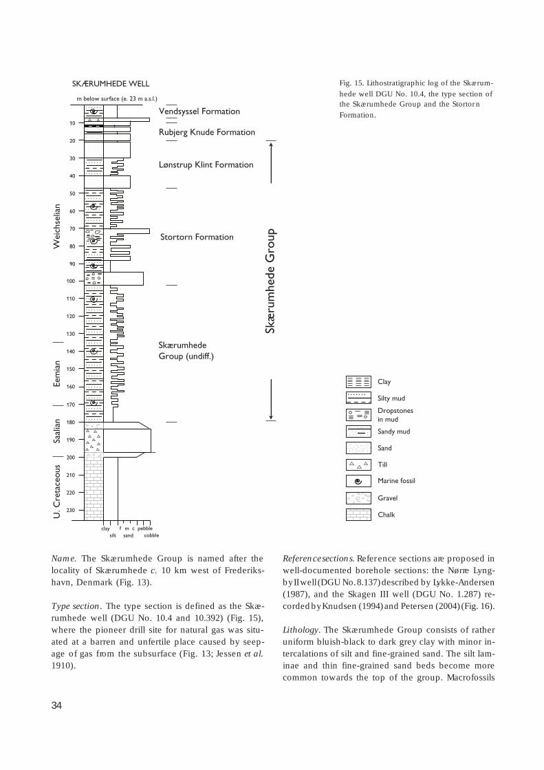
34
Name. The Skærumhede Group is named after thelocality of Skærumhede c. 10 km west of Frederiks-havn, Denmark (Fig. 13).
Type section. The type section is defined as the Skæ-rumhede well (DGU No. 10.4 and 10.392) (Fig. 15),where the pioneer drill site for natural gas was situ-ated at a barren and unfertile place caused by seep-age of gas from the subsurface (Fig. 13; Jessen et al.1910).
Reference sections. Reference sections are proposed inwell-documented borehole sections: the Nørre Lyng-by II well (DGU No. 8.137) described by Lykke-Andersen(1987), and the Skagen III well (DGU No. 1.287) re-corded by Knudsen (1994) and Petersen (2004) (Fig. 16).
Lithology. The Skærumhede Group consists of ratheruniform bluish-black to dark grey clay with minor in-tercalations of silt and fine-grained sand. The silt lam-inae and thin fine-grained sand beds become morecommon towards the top of the group. Macrofossils
Vendsyssel Formation
Rubjerg Knude Formation
Lønstrup Klint Formation
Stortorn Formation
SkærumhedeGroup (undiff.)
Clay
Silty mud
Dropstones in mud
Sandy mud
Sand
Till
Gravel
Chalk
Skæ
rum
hede
Gro
up
10
20
30
40
50
60
70
80
90
100
110
120
130
140
150
160
170
180
190
200
210
220
230
claysilt sand cobble
pebblef m c
SKÆRUMHEDE WELL
Wei
chse
lian
U. C
reta
ceou
sSa
alia
nEe
mia
n
m below surface (e. 23 m a.s.l.)
Marine fossil
Fig. 15. Lithostratigraphic log of the Skærum-
hede well DGU No. 10.4, the type section ofthe Skærumhede Group and the Stortorn
Formation.

35
are present through most of the group but decreasein abundance towards the top (Jessen et al.1910). Drop-stones are present in the middle of the group andincrease in abundance towards the uppermost part,in which graded silts and sands are intercalated withgrey mud.
Boundaries. The lower boundary is the unconformityon top of the Saalian till. The upper boundary is anunconformity overlain by coarse clastic sediments in-terpreted as a residual boulder bed (Unit B of Sadolinet al. 1997).
Thickness. The thickness of the group varies fromnearly 130 m in the type section in the Skærumhedewell, to c. 48 m in the Nørre Lyngby well and c. 45 min the Skagen III well (Fig. 16).
Distribution. Knowledge of the distribution of thegroup in the vicinity of Rubjerg Knude is based onthe Skærumhede well (DGU No. 10.4), the Nørre Lyng-by well (DGU No. 8.137) and the Skagen well (DGUNo. 1.287; Figs 13, 16). The group is also known fromwells in the northern part of Vendsyssel and the islandsof Læsø and Anholt in the Kattegat. According to theserecords, the group extends from the western part ofthe Kattegat at Frederikshavn and Læsø, towards thesouth central part of Vendsyssel, from where it con-tinues offshore between Anholt and Djursland (Knud-sen 1994, fig. 3). The group extends offshore into thestrait between Læsø and the Swedish coast. The south-ward extent is not known, but is probably up to about30 km south of Anholt. The extent to the north is alsouncertain and has not yet been mapped. It is inferredthat it may occur in the western part of the Skagerrak(Knudsen 1994) and it may also extend out into thenorthern part of the North Sea.
Age. The age of the group extends from the beginningof the Eemian, about 130 000 years B.P. (Knudsen 1994),to the latest part of the Middle Weichselian, about 30 000years B.P. (Houmark-Nielsen 1999).
Depositional environment. At the lower boundary ofthe group, red corroded flints were recognised in theSkærumhede well (Jessen et al.1910) indicating thatthe top surface of the Saalian till had been exposedand subjected to subaerial erosion prior to the trans-gression that culminated in the Eemian. During theEemian, a deep-water shelf environment was estab-lished with water depths exceeding 100 m; in the Ear-
ly Weichselian, water depths decreased dramaticallyto less than 50 m (Knudsen 1994). The decrease inwater depth continued during the Middle Weichse-lian under increasing glacial influence.
Subdivisions. The upper Skærumhede Group is sub-divided into the Stortorn and Lønstrup Klint Formations.The lower part of the group, mainly including the ma-rine Eemian and Lower Weichselian deposits, is pres-ently undifferentiated.
Stortorn Formation
new formation
History. In the Lønstrup Klint section, two units ofgrey-bluish clay subjected to glacial deformation havebeen distinguished, the diluvial clay and the Portlandiaarctica clay (Jessen 1931). The latter unit correspondsto the so-called Older Yoldia Clay (Ældre Yoldialer inDanish), which in the Skærumhede well was referredto as the Portlandia arctica zone and in the cross-section of Lønstrup Klint is indicated to occur at threelocalities (Jessen 1931). The most impressive of theseis the Stortorn site, where dark grey – black clay, richin mollusc shells, crops out (Fig. 21). The site is inac-cessible, or difficult of access, since the slippery claysoccur in the breaker zone at the foot of the almostvertical cliff section. The other two localities are thecliff sections just beyond the town Lønstrup, locallynamed ‘Lille Blå’ (little blue), and the clif f section be-low the northern corner of the Mårup churchyard. Atall three sites, the unit is tectonically disturbed whichhampers detailed logging of the succession. In addi-tion, the formation occurs locally in the lower thrust-sheet duplexes north of Mårup Church and in theMoserende cliff section (see description of that sec-tion, below).
Name. The formation is named after the Stortorn cliffsection at Lønstrup Klint. The formation is here incor-porated within the lowermost thrust unit in the Stor-torn Section (see below).
Type section. The type section for the formation is theSkærumhede well, DGU No. 10.4 (Figs 14, 15).
Reference sections. The reference sections for the for-mation are the outcrops at Stortorn and north of thenorthern corner of Mårup churchyard (Fig. 17) in the

36
Weichselian
Saalian
Holocene
Upper Cretaceous
Eemian
Vendsyssel Fm
Kattegat Till Fm
Rubjerg Kn. Fm
LønstrupKl. Fm
Lønstrup Kl. Fm
Stortorn Fm
StortornFm
SkærumhedeGroup (undiff.)
Stortorn Fm
Lønstrup KlintFm
claysilt sand cobble
pebblef m c
10
20
30
40
50
60
70
80
90
100
110
120
130
140
150
160
170
180
190
200
10
20
30
40
50
60
70
80
90
100
110
120
130
140
150
160
170
180
190
200
210
220
230
claysilt sand cobble
pebblef m c
siltclay
sand cobblepebblef m c
NØRRE LYNGBY
m below surface (e. 20 m a.s.l.)
SKÆRUMHEDE
m below surface (e. 23 m a.s.l.)
SKAGEN
m below surface (e. 3 m a.s.l.)
10
20
30
40
50
60
70
80
90
100
110
120
130
140
150
Vendsyssel Fm
Clay
Silty mud
Dropstones in clay and silty mud
Sandy mud
Sand
Till
Gravel
Chalk
Marine fossils
Vendsys
sel Fm
Rubjerg
Kn. Fm

37
mud sandf. m. c.
gr.pb.co.
0 m
5
10
15
20
25
Sandy mud
Sand
Dropstones in mud
Gravel
Shells
Lamination
Structureless
Climbing ripples
Troughcross-bedding
Ball-and-pillow /convolute bedding
Thrust fault
Clayey mud
Current ripplecross-lamination
Vendsyssel Formation
Dune sand
Lønstrup Klint Formation
Skæ
rum
hede
Gro
up
X AAR 4069
Stortorn Formation
Unconformity
Thrust zone
Fig. 17. Sedimentological log of the succession in the southern part of the Ribjerg Section (above the ‘Store Blå’). The Stortorn
Formation records an arctic marine deposit, yielding shells typical of this environment: Hiatella arctica, Mya truncata and Portlan-dia arctica. The boundary between the Stortorn and Lønstrup Klint Formations constitutes a thrust-fault breccia indicating dif feren-
tiation into thrust-fault duplex segments of the Skærumhede Group. The Vendsyssel Formation at the top of the section wasdeposited on an erosional unconformity with a lag conglomerate at the base. The location of the sample collected for 14C dating
(AAR 4069) is indicated (see Table 2).
Facing page:
Fig. 16. Simplified lithological logs from three thoroughly documented wells in Vendsyssel (Nørre Lyngby: DGU No. 8.137; Skærum-hede: DGU No. 10.4; Skagen: DGU No. 1.287, for location see Fig. 13). The logs illustrate the stratigraphic correlation of the units
defined in the investigation of the Rubjerg Knude Glaciotectonic Complex. The difference in thickness of Eemian–Weichseliandeposits mainly reflects the average content of sand; the Skagen well represents a deeper marine depositional environment com-
pared to the Skærumhede well. Note that the Cretaceous deposits in the Skagen well comprise Turonian–Cenomanian greensands.The figure is based on information from Jessen et al. (1910), Bahnson et al. (1974), Lykke-Andersen (1987), Lykke-Andersen &
Knudsen (1991), Knudsen (1994) and Petersen (2004).
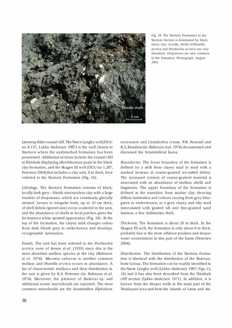
38
Lønstrup Klint coastal cliff. The Nørre Lyngby well (DGUno 8.137, Lykke-Andersen 1987) is the well closest toStortorn where the undisturbed formation has beenpenetrated. Additional sections include the coastal clif fat Hirtshals displaying allochthonous peats in the blackclay formation, and the Skagen III well (DGU no 1.287;Petersen 2004) that includes a clay unit, 8 m thick, herereferred to the Stortorn Formation (Fig. 16).
Lithology. The Stortorn Formation consists of black,locally dark grey – bluish structureless clay with a largenumber of dropstones, which are commonly glaciallystriated. Lenses or irregular beds, up to 10 cm thick,of shell debris (gravel-size) occur scattered in the unit,and the abundance of shells in local patches gives theformation a white spotted appearance (Fig. 18). At thetop of the formation, the clayey mud changes colourfrom dark bluish grey to violet-brown and developsrecognisable lamination.
Fossils. The unit has been referred to the Portlandiaarctica zone of Jessen et al. (1910) since this is themost abundant mollusc species in the clay (Bahnsonet al. 1974). Macoma calcarea is another commonmollusc and Hiatella arctica occurs in abundance. Alist of characteristic molluscs and their distribution inthe unit is given by K.S. Petersen (in: Bahnson et al.1974). Moreover, the presence of Balanus sp. andadditional erratic macrofossils are reported. The mostcommon microfossils are the foraminifers Elphidium
excavatum and Cassidulina crassa. P.B. Konradi andK.L. Knudsen (in: Bahnson et al . 1974) documented anddiscussed the foraminiferal fauna.
Boundaries. The lower boundary of the formation isdefined by a shift from clayey mud to mud with amarked increase in coarse-grained ice-rafted debris.The increased content of coarse-grained material isassociated with an abundance of mollusc shells andfragments. The upper boundary of the formation isdefined at the transition from marine clay showingdiffuse lamination and colours varying from grey blue-green to violet-brown, to a grey clayey and silty mudintercalated with graded silt and fine-grained sandlaminae a few millimetres thick.
Thickness. The formation is about 20 m thick. In theSkagen III well, the formation is only about 8 m thick,probably due to the more offshore position and deeperwater environment in this part of the basin (Petersen2004).
Distribution. The distribution of the Stortorn Forma-tion is identical with the distribution of the Skærum-hede Group. The formation can be readily identified inthe Nørre Lyngby well (Lykke-Andersen 1987; Figs 13,16) and it has also been described from the Hirtshalscliff section (Lykke-Andersen 1971). In addition, it isknown from the deeper wells in the main part of theVendsyssel area and from the islands of Læsø and An-
Hiatella shells
5 cm
Fig. 18. The Stortorn Formation in the
Stortorn Section is dominated by blacksticky clay. Locally, shells of Hiatella
arctica and Portlandia arctica are veryabundant. Dropstones are also common
in the formation. Photograph: August2001.
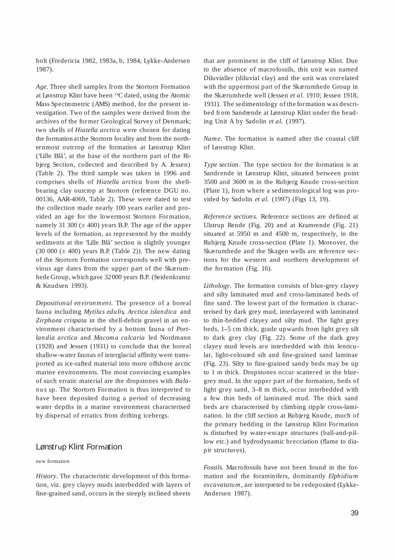
39
holt (Fredericia 1982, 1983a, b, 1984; Lykke-Andersen1987).
Age. Three shell samples from the Stortorn Formationat Lønstrup Klint have been 14C dated, using the AtomicMass Spectrometric (AMS) method, for the present in-vestigation. Two of the samples were derived from thearchives of the former Geological Survey of Denmark;two shells of Hiatella arctica were chosen for datingthe formation at the Stortorn locality and from the north-ernmost outcrop of the formation at Lønstrup Klint(‘Lille Blå’, at the base of the northern part of the Ri-bjerg Section, collected and described by A. Jessen)(Table 2). The third sample was taken in 1996 andcomprises shells of Hiatella arctica from the shell-bearing clay outcrop at Stortorn (reference DGU no.00136, AAR-4069, Table 2). These were dated to testthe collection made nearly 100 years earlier and pro-vided an age for the lowermost Stortorn Formation,namely 31 300 (± 400) years B.P. The age of the upperlevels of the formation, as represented by the muddysediments at the ‘Lille Blå’ section is slightly younger(30 000 (± 400) years B.P. (Table 2)). The new datingof the Stortorn Formation corresponds well with pre-vious age dates from the upper part of the Skærum-hede Group, which gave 32 000 years B.P. (Seidenkrantz& Knudsen 1993).
Depositional environment. The presence of a borealfauna including Mytilus edulis, Arctica islandica andZirphaea crispata in the shell-debris gravel in an en-vironment characterised by a bottom fauna of Port-landia arctica and Macoma calcaria led Nordmann(1928) and Jessen (1931) to conclude that the borealshallow-water faunas of interglacial affinity were trans-ported as ice-rafted material into more offshore arcticmarine environments. The most convincing examplesof such erratic material are the dropstones with Bala-nus sp. The Stortorn Formation is thus interpreted tohave been deposited during a period of decreasingwater depths in a marine environment characterisedby dispersal of erratics from drifting icebergs.
Lønstrup Klint Formation
new formation
History. The characteristic development of this forma-tion, viz. grey clayey muds interbedded with layers offine-grained sand, occurs in the steeply inclined sheets
that are prominent in the cliff of Lønstrup Klint. Dueto the absence of macrofossils, this unit was namedDiluvialler (diluvial clay) and the unit was correlatedwith the uppermost part of the Skærumhede Group inthe Skærumhede well (Jessen et al. 1910; Jessen 1918,1931). The sedimentology of the formation was descri-bed from Sandrende at Lønstrup Klint under the head-ing Unit A by Sadolin et al. (1997).
Name. The formation is named after the coastal cliffof Lønstrup Klint.
Type section. The type section for the formation is atSandrende in Lønstrup Klint, situated between point3500 and 3600 m in the Rubjerg Knude cross-section(Plate 1), from where a sedimentological log was pro-vided by Sadolin et al. (1997) (Figs 13, 19).
Reference sections. Reference sections are defined atUlstrup Rende (Fig. 20) and at Kramrende (Fig. 21)situated at 5950 m and 4500 m, respectively, in theRubjerg Knude cross-section (Plate 1). Moreover, theSkærumhede and the Skagen wells are reference sec-tions for the western and northern development ofthe formation (Fig. 16).
Lithology. The formation consists of blue-grey clayeyand silty laminated mud and cross-laminated beds offine sand. The lowest part of the formation is charac-terised by dark grey mud, interlayered with laminatedto thin-bedded clayey and silty mud. The light greybeds, 1–5 cm thick, grade upwards from light grey siltto dark grey clay (Fig. 22). Some of the dark greyclayey mud levels are interbedded with thin lenticu-lar, light-coloured silt and fine-grained sand laminae(Fig. 23). Silty to fine-grained sandy beds may be upto 1 m thick. Dropstones occur scattered in the blue-grey mud. In the upper part of the formation, beds oflight grey sand, 3–8 m thick, occur interbedded witha few thin beds of laminated mud. The thick sandbeds are characterised by climbing ripple cross-lami-nation. In the cliff section at Rubjerg Knude, much ofthe primary bedding in the Lønstrup Klint Formationis disturbed by water-escape structures (ball-and-pil-low etc.) and hydrodynamic brecciation (flame to dia-pir structures).
Fossils. Macrofossils have not been found in the for-mation and the foraminifers, dominantly Elphidiumexcavatatum, are interpreted to be redeposited (Lykke-Andersen 1987).
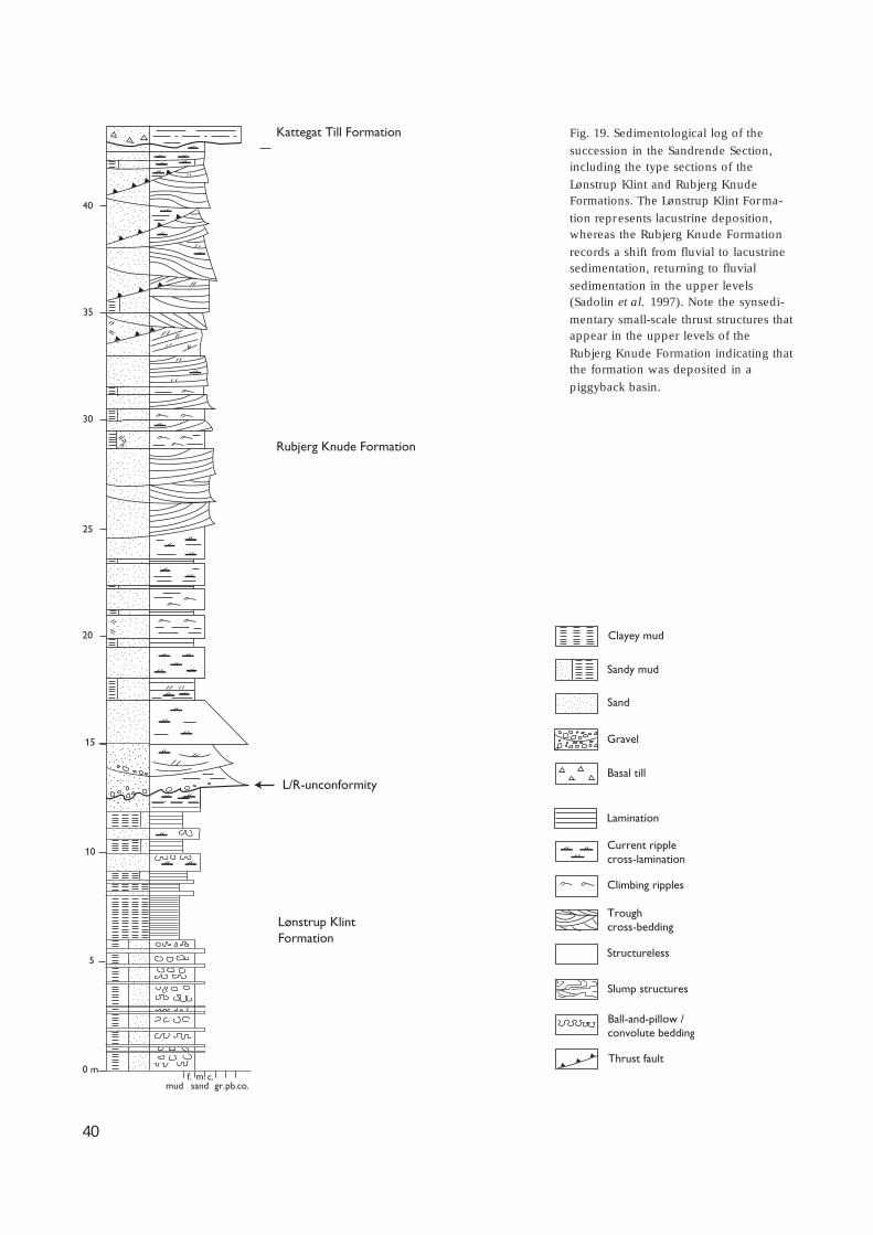
40
mud sandf. m. c.
gr.pb.co.
5
10
15
0 m
L/R-unconformity
20
25
30
35
40
Sandy mud
Sand
Gravel
Basal till
Lamination
Structureless
Climbing ripples
Troughcross-bedding
Slump structures
Ball-and-pillow / convolute bedding
Thrust fault
Rubjerg Knude Formation
Lønstrup KlintFormation
Kattegat Till Formation
Clayey mud
Current ripplecross-lamination
Fig. 19. Sedimentological log of the
succession in the Sandrende Section,including the type sections of the
Lønstrup Klint and Rubjerg KnudeFormations. The Lønstrup Klint Forma-
tion represents lacustrine deposition,whereas the Rubjerg Knude Formation
records a shift from fluvial to lacustrinesedimentation, returning to fluvial
sedimentation in the upper levels(Sadolin et al. 1997). Note the synsedi-
mentary small-scale thrust structures thatappear in the upper levels of the
Rubjerg Knude Formation indicating thatthe formation was deposited in a
piggyback basin.
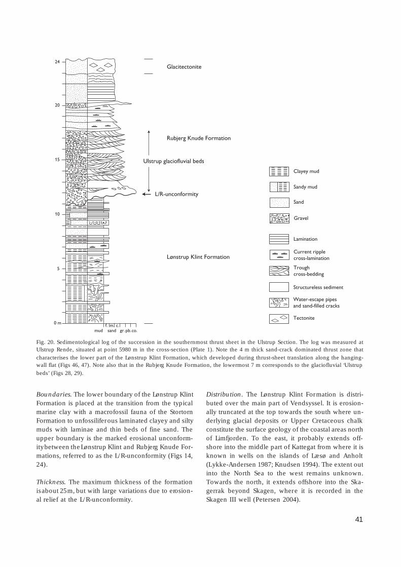
41
Boundaries. The lower boundary of the Lønstrup KlintFormation is placed at the transition from the typicalmarine clay with a macrofossil fauna of the StortornFormation to unfossiliferous laminated clayey and siltymuds with laminae and thin beds of fine sand. Theupper boundary is the marked erosional unconform-ity between the Lønstrup Klint and Rubjerg Knude For-mations, referred to as the L/R-unconformity (Figs 14,24).
Thickness. The maximum thickness of the formationis about 25 m, but with large variations due to erosion-al relief at the L/R-unconformity.
Distribution. The Lønstrup Klint Formation is distri-buted over the main part of Vendsyssel. It is erosion-ally truncated at the top towards the south where un-derlying glacial deposits or Upper Cretaceous chalkconstitute the surface geology of the coastal areas northof Limfjorden. To the east, it probably extends off-shore into the middle part of Kattegat from where it isknown in wells on the islands of Læsø and Anholt(Lykke-Andersen 1987; Knudsen 1994). The extent outinto the North Sea to the west remains unknown.Towards the north, it extends offshore into the Ska-gerrak beyond Skagen, where it is recorded in theSkagen III well (Petersen 2004).
24
20
15
10
5
0 m
mud sandf. m. c.
gr. pb.co.
Glacitectonite
Rubjerg Knude Formation
Ulstrup glaciofluvial beds
Lønstrup Klint Formation
Clayey mud
Sandy mud
Sand
Gravel
Lamination
Current ripplecross-lamination
Troughcross-bedding
Tectonite
Water-escape pipesand sand-filled cracks
Structureless sediment
L/R-unconformity
Fig. 20. Sedimentological log of the succession in the southernmost thrust sheet in the Ulstrup Section. The log was measured atUlstrup Rende, situated at point 5980 m in the cross-section (Plate 1). Note the 4 m thick sand-crack dominated thrust zone that
characterises the lower part of the Lønstrup Klint Formation, which developed during thrust-sheet translation along the hanging-wall flat (Figs 46, 47). Note also that in the Rubjerg Knude Formation, the lowermost 7 m corresponds to the glaciofluvial ‘Ulstrup
beds’ (Figs 28, 29).
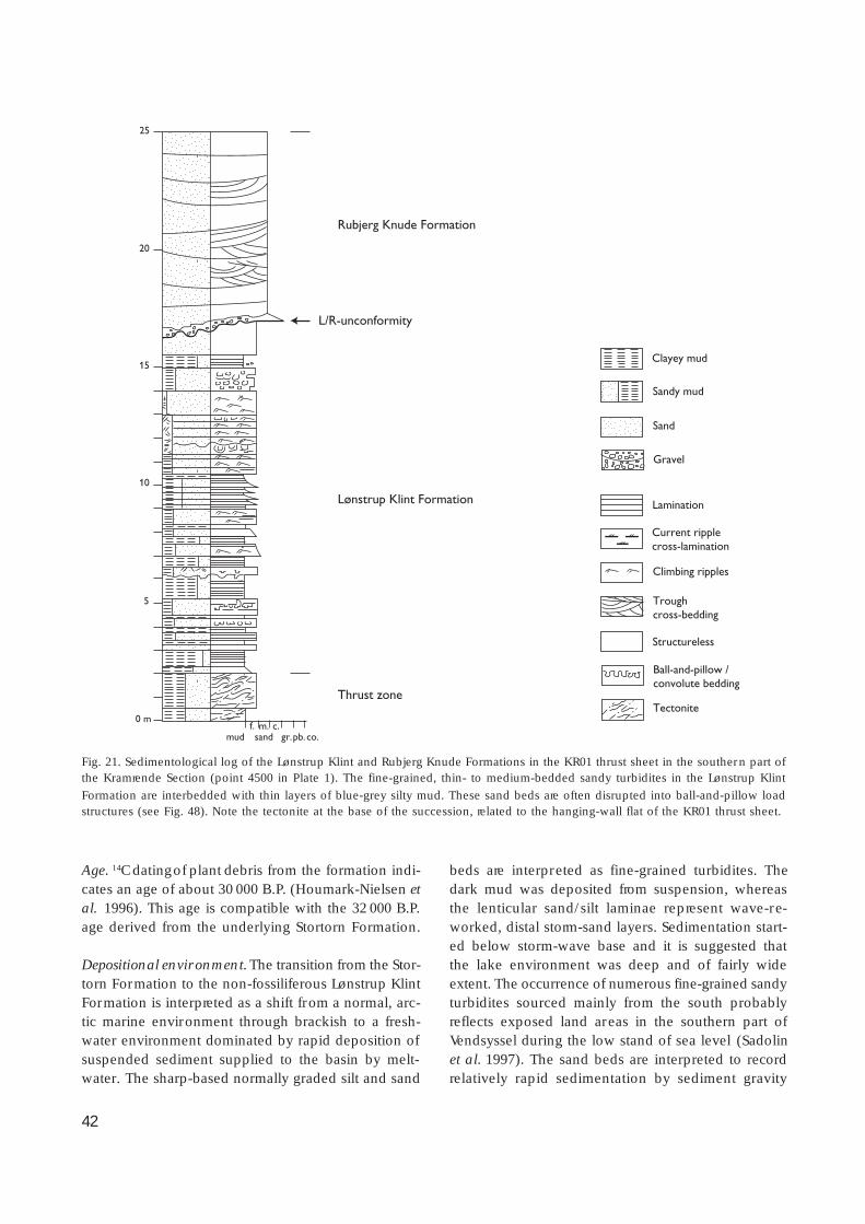
42
Age. 14C dating of plant debris from the formation indi-cates an age of about 30 000 B.P. (Houmark-Nielsen etal. 1996). This age is compatible with the 32 000 B.P.age derived from the underlying Stortorn Formation.
Depositional environment. The transition from the Stor-torn Formation to the non-fossiliferous Lønstrup KlintFormation is interpreted as a shift from a normal, arc-tic marine environment through brackish to a fresh-water environment dominated by rapid deposition ofsuspended sediment supplied to the basin by melt-water. The sharp-based normally graded silt and sand
beds are interpreted as fine-grained turbidites. Thedark mud was deposited from suspension, whereasthe lenticular sand/silt laminae represent wave-re-worked, distal storm-sand layers. Sedimentation start-ed below storm-wave base and it is suggested thatthe lake environment was deep and of fairly wideextent. The occurrence of numerous fine-grained sandyturbidites sourced mainly from the south probablyreflects exposed land areas in the southern part ofVendsyssel during the low stand of sea level (Sadolinet al. 1997). The sand beds are interpreted to recordrelatively rapid sedimentation by sediment gravity
0 m
5
10
15
20
25
Thrust zone
Rubjerg Knude Formation
Lønstrup Klint Formation
Sandy mud
Sand
Gravel
Lamination
Structureless
Climbing ripples
Troughcross-bedding
Ball-and-pillow /convolute bedding
Tectonite
Clayey mud
Current ripplecross-lamination
mud sandf. m. c.
gr.pb. co.
L/R-unconformity
Fig. 21. Sedimentological log of the Lønstrup Klint and Rubjerg Knude Formations in the KR01 thrust sheet in the southern part ofthe Kramrende Section (point 4500 in Plate 1). The fine-grained, thin- to medium-bedded sandy turbidites in the Lønstrup Klint
Formation are interbedded with thin layers of blue-grey silty mud. These sand beds are often disrupted into ball-and-pillow loadstructures (see Fig. 48). Note the tectonite at the base of the succession, related to the hanging-wall flat of the KR01 thrust sheet.

43
flows in a glaciolacustrine environment; the thickestof these beds may represent deposition within onesummer of sediment derived from the southern slopesof the basin (Sadolin et al.1997).
Hydrodynamic deformation of the strata was initia-ted at a very early stage in the glaciotectonic process,as loading by the superposed Rubjerg Knude Forma-tion and by glaciotectonic thrust sheets resulted inincreasing pore-water pressure. Hydrodynamic brec-ciation continued during deformation until the dis-placements of thrust sheets ceased.
Upper Weichselian lithostratigraphicunits
Rubjerg Knude Formationnew formation
History. In the steep cliff section at Rubjerg Knude,the thrust sheets, consisting of the grey-blue colouredclay of the Lønstrup Klint Formation, are deposition-ally overlain and structurally underlain by light-col-oured yellowish sand, named Diluvialsand (diluvialsand) by Jessen (1918, 1931). The succession was re-
Fig. 22. Laminated to thin-bedded clayey
and silty mud in the lower part of theLønstrup Klint Formation in the Rubjerg
Knude Fyr Section. The bedding isdefined by layers grading from light
grey silt to dark grey clay, and thesharp-based normally graded beds are
interpreted as fine-grained turbidites.The coin for scale is 2.5 cm in diameter.
Photograph: September 1985.
Fig. 23. Dark grey clayey mud interbed-
ded with thin lenticular, light colouredsilt and fine-grained sand laminae. The
mud was deposited from suspension,whereas the lenticular laminae represent
wave-reworked, distal storm-sand layers,deposited below storm-wave base.
Photograph: June 1993.

44
Fig. 24. The L/R-unconformity is steeply inclined in the GR08 thrust sheet. Note the large-scale cross-bedding in the basal unit of theRubjerg Knude Formation, which onlaps the unconformity (R-onlap). Photograph: June 1993; rucksack for scale.
L/R-unconformity
0 m
13
10
Ulstrup glaciolacustrine beds
Lønstrup Klint Formation
Rubjerg Knude Formation
Thrust zone
5
mud sandf. m. c.
gr.pb. co.
Sandy mud
Sand
Gravel
Lamination
Structureless sediment
Troughcross-bedding
Ball-and-pillow convolute bedding
Water-escape pipesand sand-filled cracks
Thrust fault
Clayey mud
Current ripplecross-lamination
Fig. 25. Sedimentological log of the succession in the northern thrust sheet in the Ulstrup Section. The log was measured near the
Ulstrup steps at point 5625 m in the cross-section (Plate 1). The base of the log is the hanging-wall flat of the UL02 thrust sheet andthe lowermost 2 m constitute the thrust zone. The boundary between the Lønstrup Klint Formation and the Ulstrup glaciolacustrine
beds above (lower unit of the Rubjerg Knude Formation) is a flat, non-erosional surface but can be traced to the northern part of theUL02 thrust sheet where this boundary is a clear erosional unconformity.

45
ferred to as units B–D in the sedimentological studyby Sadolin et al. (1997).
Name. The formation is named after Rubjerg Knude,the highest part of the Lønstrup Klint cliff..
Type section . The type section is at Sandrende in theLønstrup Klint cliff section (Figs 13, 19).
Reference section. Four reference sections are defined,all situated in the vicinity of Rubjerg Knude. In thedistal part of the Rubjerg Knude Glaciotectonic Com-plex, two reference sections are defined at Ulstrup.The first of these is located in Ulstrup Rende at point
5900 m in the Rubjerg Knude cross-section (Plate 1)which demonstrates the presence of coarse-grainedglaciofluvial channel fill deposits (Fig. 19). The secondreference section at Ulstrup is located at point 5450 min Plate 1 and documents the occurrence of fine-grainedclayey muddy glaciolacustrine beds in the formation(Fig. 25). The third reference section is situated atMartørv Bakker (point 4850 m in Plate 1), which dem-onstrates diamictitic sediments including slump unitsin a piggyback basin (Fig. 26). The fourth referencesection is located at Moserende at point 1750 m inPlate 1. This section illustrates the formation in a pig-gyback basin situated in a proximal position in theRubjerg Knude Glaciotectonic Complex (Fig. 27).
23
mud sandf. m. c.
gr.pb. co.
20
15
10
5
0 m
Vendsyssel Formation
Holocene peat ( martørv )
Aeolian sand
Rubjerg Knude Formation(including diamict sedimentsand slump-folded units)
Lønstrup Klint Formation
L/R-unconformity
Erosional unconformity
Sandy mud
Sand
Gravel
Lamination
Structureless sediment
Troughcross-bedding
Mud with scatteredpebbles and cobbles
Slump structures
Ball-and-pillow convolute bedding
Clayey mud
Current ripplecross-lamination
Fig. 26. Geological log of the diamict sediments and slump-fold structures, which represent the Rubjerg Knude Formation in thepiggyback basin on the back of the MB02 thrust sheet in the Martørv Bakker Section, point 4880 in the cross-section (Plate 1).
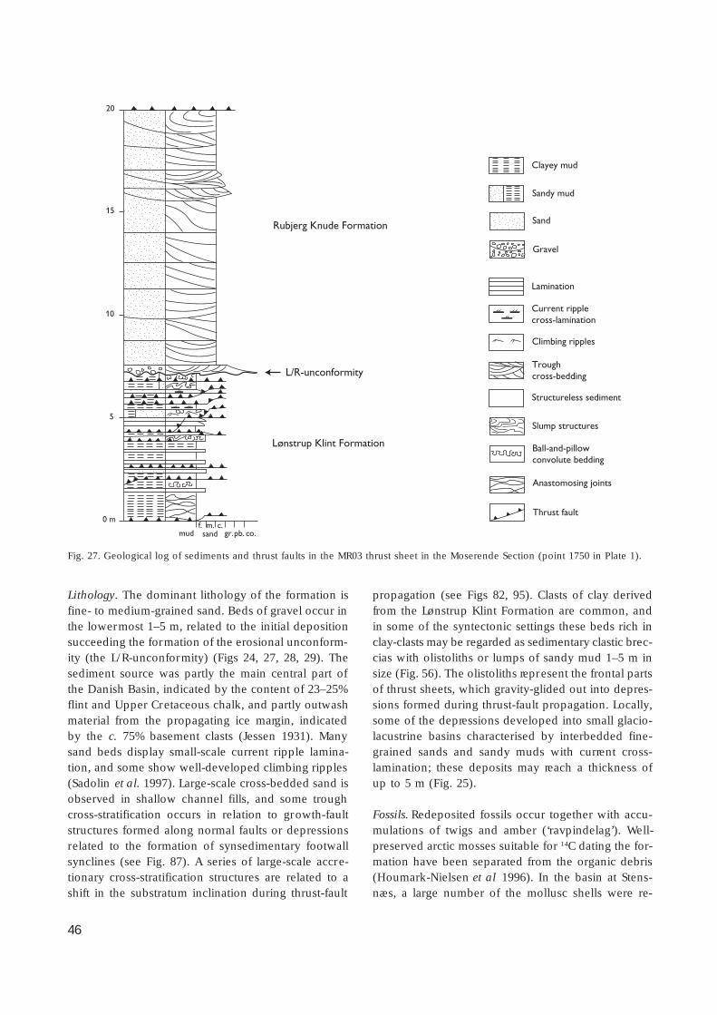
46
Lithology. The dominant lithology of the formation isfine- to medium-grained sand. Beds of gravel occur inthe lowermost 1–5 m, related to the initial depositionsucceeding the formation of the erosional unconform-ity (the L/R-unconformity) (Figs 24, 27, 28, 29). Thesediment source was partly the main central part ofthe Danish Basin, indicated by the content of 23–25%flint and Upper Cretaceous chalk, and partly outwashmaterial from the propagating ice margin, indicatedby the c. 75% basement clasts (Jessen 1931). Manysand beds display small-scale current ripple lamina-tion, and some show well-developed climbing ripples(Sadolin et al. 1997). Large-scale cross-bedded sand isobserved in shallow channel fills, and some troughcross-stratification occurs in relation to growth-faultstructures formed along normal faults or depressionsrelated to the formation of synsedimentary footwallsynclines (see Fig. 87). A series of large-scale accre-tionary cross-stratification structures are related to ashift in the substratum inclination during thrust-fault
propagation (see Figs 82, 95). Clasts of clay derivedfrom the Lønstrup Klint Formation are common, andin some of the syntectonic settings these beds rich inclay-clasts may be regarded as sedimentary clastic brec-cias with olistoliths or lumps of sandy mud 1–5 m insize (Fig. 56). The olistoliths represent the frontal partsof thrust sheets, which gravity-glided out into depres-sions formed during thrust-fault propagation. Locally,some of the depressions developed into small glacio-lacustrine basins characterised by interbedded fine-grained sands and sandy muds with current cross-lamination; these deposits may reach a thickness ofup to 5 m (Fig. 25).
Fossils. Redeposited fossils occur together with accu-mulations of twigs and amber (‘ravpindelag’). Well-preserved arctic mosses suitable for 14C dating the for-mation have been separated from the organic debris(Houmark-Nielsen et al 1996). In the basin at Stens-næs, a large number of the mollusc shells were re-
L/R-unconformity
mud sandf. m. c.
gr.pb. co.
0 m
5
10
15
20
Sandy mud
Sand
Gravel
Lamination
Structureless sediment
Climbing ripples
Troughcross-bedding
Slump structures
Ball-and-pillow convolute bedding
Anastomosing joints
Thrust fault
Rubjerg Knude Formation
Lønstrup Klint Formation
Clayey mud
Current ripplecross-lamination
Fig. 27. Geological log of sediments and thrust faults in the MR03 thrust sheet in the Moserende Section (point 1750 in Plate 1).
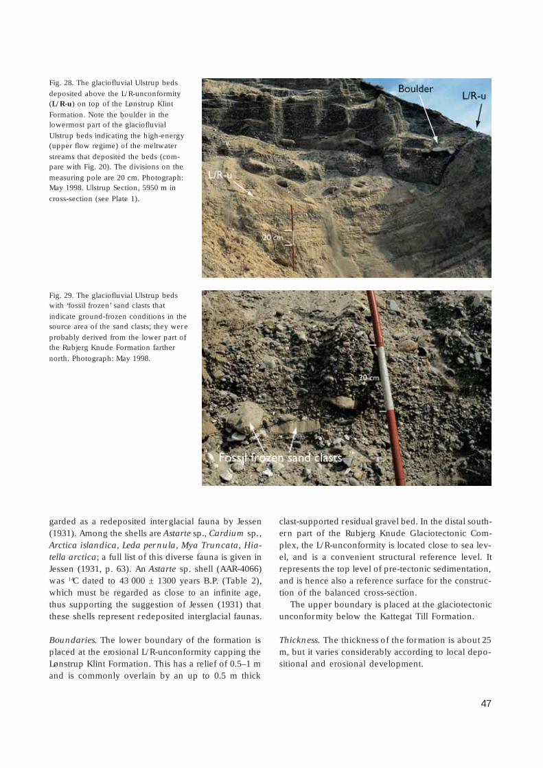
47
garded as a redeposited interglacial fauna by Jessen(1931). Among the shells are Astarte sp., Cardium sp.,Arctica islandica, Leda pernula, Mya Truncata, Hia-tella arctica; a full list of this diverse fauna is given inJessen (1931, p. 63). An Astarte sp. shell (AAR-4066)was 14C dated to 43 000 ± 1300 years B.P. (Table 2),which must be regarded as close to an infinite age,thus supporting the suggestion of Jessen (1931) thatthese shells represent redeposited interglacial faunas.
Boundaries. The lower boundary of the formation isplaced at the erosional L/R-unconformity capping theLønstrup Klint Formation. This has a relief of 0.5–1 mand is commonly overlain by an up to 0.5 m thick
clast-supported residual gravel bed. In the distal south-ern part of the Rubjerg Knude Glaciotectonic Com-plex, the L/R-unconformity is located close to sea lev-el, and is a convenient structural reference level. Itrepresents the top level of pre-tectonic sedimentation,and is hence also a reference surface for the construc-tion of the balanced cross-section.
The upper boundary is placed at the glaciotectonicunconformity below the Kattegat Till Formation.
Thickness. The thickness of the formation is about 25m, but it varies considerably according to local depo-sitional and erosional development.
Fig. 28. The glaciofluvial Ulstrup beds
deposited above the L/R-unconformity(L/R-u) on top of the Lønstrup Klint
Formation. Note the boulder in thelowermost part of the glaciofluvial
Ulstrup beds indicating the high-energy(upper flow regime) of the meltwater
streams that deposited the beds (com-pare with Fig. 20). The divisions on the
measuring pole are 20 cm. Photograph:May 1998. Ulstrup Section, 5950 m in
cross-section (see Plate 1).
Fig. 29. The glaciofluvial Ulstrup bedswith ‘fossil frozen’ sand clasts that
indicate ground-frozen conditions in thesource area of the sand clasts; they were
probably derived from the lower part ofthe Rubjerg Knude Formation farther
north. Photograph: May 1998.
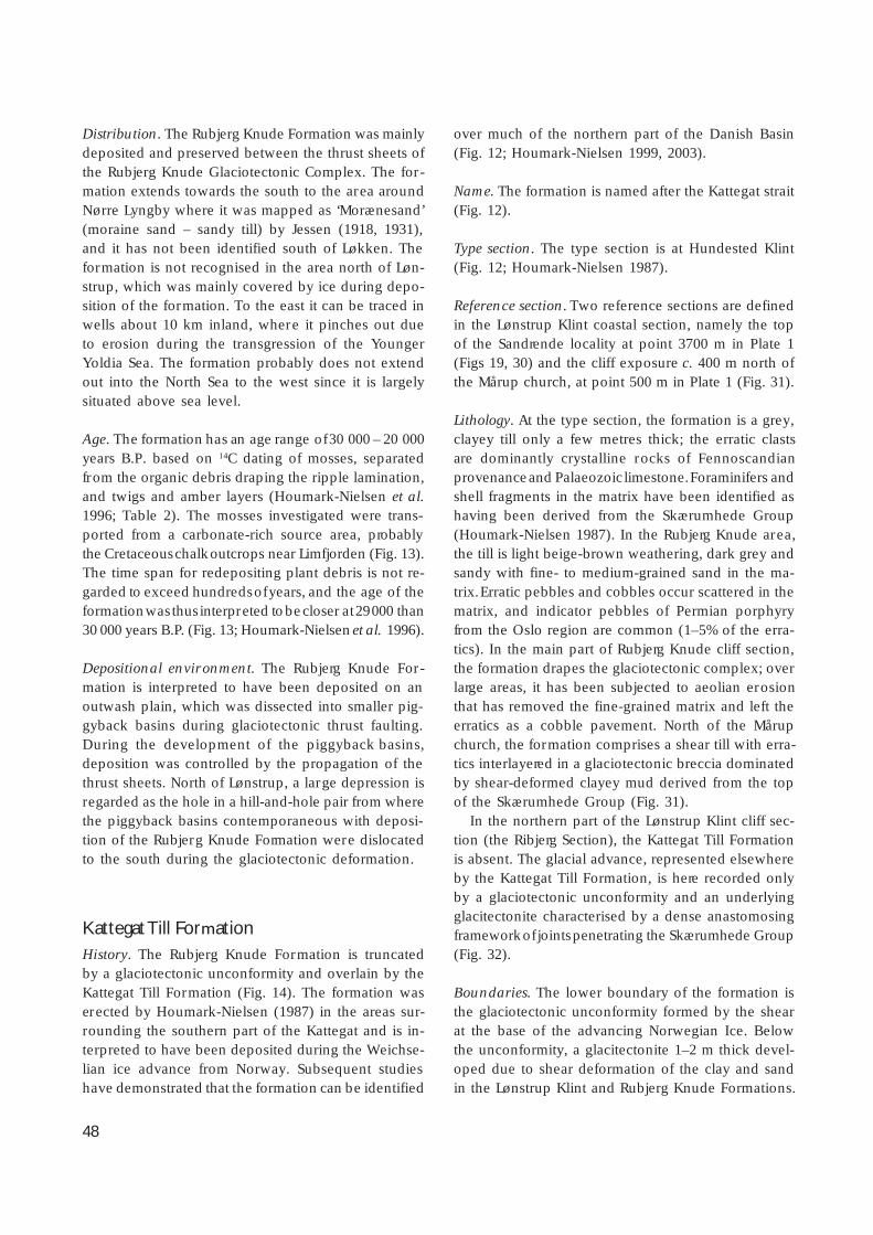
48
Distribution. The Rubjerg Knude Formation was mainlydeposited and preserved between the thrust sheets ofthe Rubjerg Knude Glaciotectonic Complex. The for-mation extends towards the south to the area aroundNørre Lyngby where it was mapped as ‘Morænesand’(moraine sand – sandy till) by Jessen (1918, 1931),and it has not been identified south of Løkken. Theformation is not recognised in the area north of Løn-strup, which was mainly covered by ice during depo-sition of the formation. To the east it can be traced inwells about 10 km inland, where it pinches out dueto erosion during the transgression of the YoungerYoldia Sea. The formation probably does not extendout into the North Sea to the west since it is largelysituated above sea level.
Age. The formation has an age range of 30 000 – 20 000years B.P. based on 14C dating of mosses, separatedfrom the organic debris draping the ripple lamination,and twigs and amber layers (Houmark-Nielsen et al.1996; Table 2). The mosses investigated were trans-ported from a carbonate-rich source area, probablythe Cretaceous chalk outcrops near Limfjorden (Fig. 13).The time span for redepositing plant debris is not re-garded to exceed hundreds of years, and the age of theformation was thus interpreted to be closer at 29 000 than30 000 years B.P. (Fig. 13; Houmark-Nielsen et al. 1996).
Depositional environment. The Rubjerg Knude For-mation is interpreted to have been deposited on anoutwash plain, which was dissected into smaller pig-gyback basins during glaciotectonic thrust faulting.During the development of the piggyback basins,deposition was controlled by the propagation of thethrust sheets. North of Lønstrup, a large depression isregarded as the hole in a hill-and-hole pair from wherethe piggyback basins contemporaneous with deposi-tion of the Rubjerg Knude Formation were dislocatedto the south during the glaciotectonic deformation.
Kattegat Till FormationHistory. The Rubjerg Knude Formation is truncatedby a glaciotectonic unconformity and overlain by theKattegat Till Formation (Fig. 14). The formation waserected by Houmark-Nielsen (1987) in the areas sur-rounding the southern part of the Kattegat and is in-terpreted to have been deposited during the Weichse-lian ice advance from Norway. Subsequent studieshave demonstrated that the formation can be identified
over much of the northern part of the Danish Basin(Fig. 12; Houmark-Nielsen 1999, 2003).
Name. The formation is named after the Kattegat strait(Fig. 12).
Type section. The type section is at Hundested Klint(Fig. 12; Houmark-Nielsen 1987).
Reference section. Two reference sections are definedin the Lønstrup Klint coastal section, namely the topof the Sandrende locality at point 3700 m in Plate 1(Figs 19, 30) and the cliff exposure c. 400 m north ofthe Mårup church, at point 500 m in Plate 1 (Fig. 31).
Lithology. At the type section, the formation is a grey,clayey till only a few metres thick; the erratic clastsare dominantly crystalline rocks of Fennoscandianprovenance and Palaeozoic limestone. Foraminifers andshell fragments in the matrix have been identified ashaving been derived from the Skærumhede Group(Houmark-Nielsen 1987). In the Rubjerg Knude area,the till is light beige-brown weathering, dark grey andsandy with fine- to medium-grained sand in the ma-trix. Erratic pebbles and cobbles occur scattered in thematrix, and indicator pebbles of Permian porphyryfrom the Oslo region are common (1–5% of the erra-tics). In the main part of Rubjerg Knude cliff section,the formation drapes the glaciotectonic complex; overlarge areas, it has been subjected to aeolian erosionthat has removed the fine-grained matrix and left theerratics as a cobble pavement. North of the Mårupchurch, the formation comprises a shear till with erra-tics interlayered in a glaciotectonic breccia dominatedby shear-deformed clayey mud derived from the topof the Skærumhede Group (Fig. 31).
In the northern part of the Lønstrup Klint cliff sec-tion (the Ribjerg Section), the Kattegat Till Formationis absent. The glacial advance, represented elsewhereby the Kattegat Till Formation, is here recorded onlyby a glaciotectonic unconformity and an underlyingglacitectonite characterised by a dense anastomosingframework of joints penetrating the Skærumhede Group(Fig. 32).
Boundaries. The lower boundary of the formation isthe glaciotectonic unconformity formed by the shearat the base of the advancing Norwegian Ice. Belowthe unconformity, a glacitectonite 1–2 m thick devel-oped due to shear deformation of the clay and sandin the Lønstrup Klint and Rubjerg Knude Formations.

49
The upper boundary is the subaerial erosional sur-face above the 1.5 m thick sandy till, commonly reducedto a 0.25 m thick residual pavement.
Thickness. The formation is up to 1.5 m thick at Ru-bjerg Knude.
Distribution. The formation has been recognised fromthe central and northern part of the west coast of Jyl-land and Vendsyssel over Djursland and Sjælland toHven and Glumslöv in the western part of Skåne,Sweden (Fig. 12; Houmark-Nielsen 2003).
Age. The age of the Kattegat Till Formation is bracke-ted by the Lønstrup Klint Formation beneath (29 000years B.P.) and the Ribjerg Formation above (26 000years B.P.) (Fig. 14, Tables 2, 3). The age is estimatedto be 27 500 ± 1000 years B.P. (Houmark-Nielsen 2003).
Depositional environment. The Kattegat Till Forma-tion is interpreted as a lodgement till. In the area be-tween Lønstrup and Mårup church, the diamict lithol-ogy of the upper Skærumhede Group suggests thatdeformation of the substratum below the glaciotec-tonic unconformity was initiated by mud-mobilisationof water-saturated clay, silt and fine-grained sand.Material, including erratic clasts from the lodgementbed along the sole of the ice, dropped into the mud-mobilised unit. During the advance of the ice, the mud-mobilised zone became consolidated, and sub-hori-zontal anastomosing joints formed in the substratum.The depositional environment therefore changed froma wet-based glacial advance to an advance over dehy-drated or even frozen substratum during the deposi-tion of the Kattegat Till Formation at Rubjerg Knude.
Fig. 30. The c. 1 m thick sandy till on top of the Sandrende Section is referred to the Kattegat Till Formation. The maximum size of
the erratic clasts is 25 cm. The marked planar erosion sur face above the till was initially formed by glacial truncation, whichsubsequently was exposed to aeolian erosion and finally covered by dunes. Photograph: July 1993.
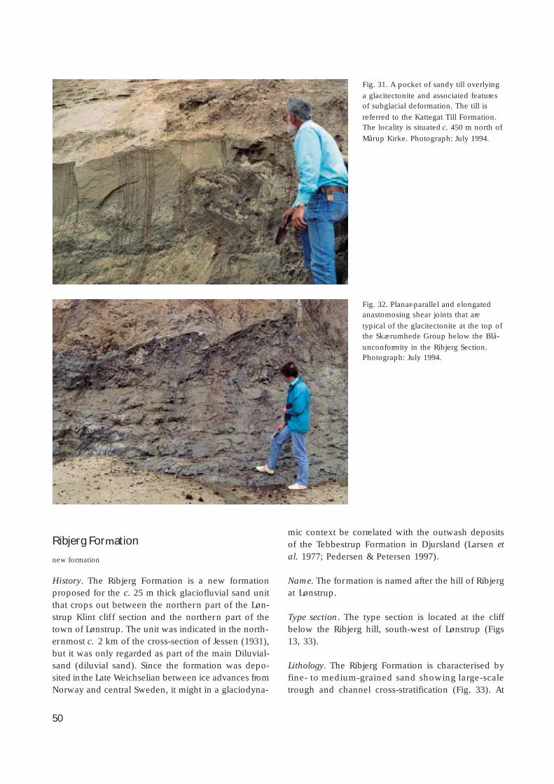
50
Ribjerg Formation
new formation
History. The Ribjerg Formation is a new formationproposed for the c. 25 m thick glaciofluvial sand unitthat crops out between the northern part of the Løn-strup Klint clif f section and the northern part of thetown of Lønstrup. The unit was indicated in the north-ernmost c. 2 km of the cross-section of Jessen (1931),but it was only regarded as part of the main Diluvial-sand (diluvial sand). Since the formation was depo-sited in the Late Weichselian between ice advances fromNorway and central Sweden, it might in a glaciodyna-
mic context be correlated with the outwash depositsof the Tebbestrup Formation in Djursland (Larsen etal. 1977; Pedersen & Petersen 1997).
Name. The formation is named after the hill of Ribjergat Lønstrup.
Type section. The type section is located at the cliffbelow the Ribjerg hill, south-west of Lønstrup (Figs13, 33).
Lithology. The Ribjerg Formation is characterised byfine- to medium-grained sand showing large-scaletrough and channel cross-stratification (Fig. 33). At
Fig. 31. A pocket of sandy till overlying
a glacitectonite and associated featuresof subglacial deformation. The till is
referred to the Kattegat Till Formation.The locality is situated c. 450 m north of
Mårup Kirke. Photograph: July 1994.
Fig. 32. Planar-parallel and elongatedanastomosing shear joints that are
typical of the glacitectonite at the top ofthe Skærumhede Group below the Blå-
unconformity in the Ribjerg Section.Photograph: July 1994.

51
the base of the formation, tabular grey mud clasts(1 × 5–10 cm in cross-section) form a lag deposit inthe fine-grained sand. Lamination outlined by heavyminerals occurs in the lowermost metre of the forma-tion and current-ripple lamination with mud chips isalso present (Fig. 33). The lower part of the formationis characterised by horizontal planar laminated fine-grained sand interlayered with thin beds (0.1–0.5 cm
thick) of clay-draped current ripples. This facies isoverlain by 0.5 m thick beds of fine- to coarse-grainedtrough cross-bedded sand. Troughs or channels, 2–5m deep and 10–15 m wide, occur in the middle andupper part of the formation (Fig. 111). In the centralpart of the troughs, the fill shows large-scale cross-stratification. Towards the margin of the troughs, thebeds decrease in thickness and display small-scale
mud sandf. m. c.
gr.pb. co.
25
20
15
10
5
0 m
Ribjerg Formation
Peat and dune sand
Mid Danish Till Formation
Glaciotectonic-unconformity
Blå-unconformity
Skærumhede Group
X R-990222
X R-990223
X R-990224
Sandy mud
Sand
Dropstones in mud
Gravel
Basal till
Shells
Lamination
Structureless
Mud clasts
Climbing ripples
Troughcross-bedding
Slump structures
Ball-and-pillow / convolute bedding
Water-escape pipesand sand-filled cracks
Tectonite
Clayey mud
Current ripplecross-lamination
X AAR 4067
Fig. 33. Sedimentological log of the Ribjerg Formation (type section) in the northernmost part of the Ribjerg Section. The formation
was deposited above the Blå-unconformity on top of the Skærumhede Group, and it is overlain by the sandy Mid Danish TillFormation. The Ribjerg Formation represents glaciofluvial deposition related to a channel-eroded foreland of an advancing glacier.
Note the sand-dykes that are interpreted to have formed by discharge of pore water due to high stream velocity. Samples collectedfor optically stimulated luminescence dating are indicated, together with their laboratory numbers (see Table 3).
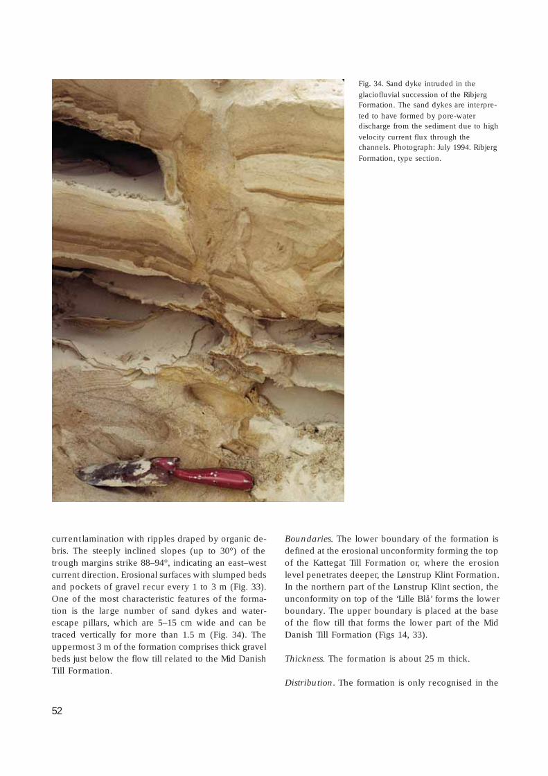
52
current lamination with ripples draped by organic de-bris. The steeply inclined slopes (up to 30°) of thetrough margins strike 88–94°, indicating an east–westcurrent direction. Erosional surfaces with slumped bedsand pockets of gravel recur every 1 to 3 m (Fig. 33).One of the most characteristic features of the forma-tion is the large number of sand dykes and water-escape pillars, which are 5–15 cm wide and can betraced vertically for more than 1.5 m (Fig. 34). Theuppermost 3 m of the formation comprises thick gravelbeds just below the flow till related to the Mid DanishTill Formation.
Boundaries. The lower boundary of the formation isdefined at the erosional unconformity forming the topof the Kattegat Till Formation or, where the erosionlevel penetrates deeper, the Lønstrup Klint Formation.In the northern part of the Lønstrup Klint section, theunconformity on top of the ‘Lille Blå’ forms the lowerboundary. The upper boundary is placed at the baseof the flow till that forms the lower part of the MidDanish Till Formation (Figs 14, 33).
Thickness. The formation is about 25 m thick.
Distribution. The formation is only recognised in the
Fig. 34. Sand dyke intruded in the
glaciofluvial succession of the RibjergFormation. The sand dykes are interpre-
ted to have formed by pore-waterdischarge from the sediment due to high
velocity current flux through thechannels. Photograph: July 1994. Ribjerg
Formation, type section.

53
vicinity of Lønstrup and towards Vennebjerg to theeast. It is inferred to have been deposited over a larg-er area of north-western Vendsyssel, which is nowcovered by the Vendsyssel Formation (see below).
Age. Three samples were collected from the lower,middle and upper part of the formation for opticallystimulated luminescence dating (R-990222, R-990223,R-990224; Table 3); these samples indicate an age of26 000 – 25 000 years B.P.
Depositional environment. The formation was depo-sited in fluvial channels cut by westward-flowing melt-water. The sand dykes and water-escape pillars areindicative of high pore-water pressure due to rapiddeposition and very fast meltwater flux through thechannels. The outwash deposits are interpreted as avalley sandur that formed in the depression resultingfrom the hole left in the hinterland of the RubjergKnude Glaciotectonic Complex. The source of the melt-water was the ice margin of the advancing ice fromcentral Sweden in the Late Weichselian.
Mid Danish Till FormationHistory. The Ribjerg Formation of the Lønstrup Klintsection is overlain by a 3 m thick grey-brown till thatis referred to the Mid Danish Till Formation (Hou-mark-Nielsen 1987, 1999, 2003). The formation was
erected by Houmark-Nielsen (1987) to encompass tillsdeposited in the southern and central part of Den-mark during the Weichselian ice advance from centralSweden. It is known from the main part of the DanishBasin east and north of the Main Stationary Line (Fig.12), and the records of its distribution in the northernpart of Denmark have recently been summarised byHoumark-Nielsen (1999, 2003) (Figs 1, 12).
Name. The name of the formation reflects the promi-nent nature of this surface deposit in central (mid)Denmark (Fig. 12).
Type section. The type section is at Ristinge Klint onthe island of Langeland (Houmark-Nielsen 1987).
Reference section. A reference section is herein de-fined at Ribjerg, SW of Lønstrup (Figs 13, 33).
Lithology. At the type locality, the Mid Danish TillFormation is a 5–8 m thick unit with at least two boul-der pavements displaying NE–SW orientated glacialstriation (Sjørring et al. 1982). The formation is a greyto brown mostly clayey massive till with about 50%crystalline erratics of Fennoscandian provenance; indi-cator clasts from the central eastern part of Sweden(Kinne-diabase) and from Jurassic sedimentary rockssituated offshore in the Kattegat (Pedersen & Petersen1997) are abundant (Houmark-Nielsen 1987).
In the reference section at Ribjerg, the formation is
Table 3. Optically stimulated luminescence dates on quartz, Rubjerg Knudeand Nørre Lyngby, Vendsyssel, northern Denmark
Stratigraphic unit Locality Lab. ID no. Material Ageka B.P.
Dose+
(Gy)W.C.‡
(%)Ref.*
Vendsyssel Fm Nørre Lyngby R-829202a Marine clay 16 ± 1 38.9 ± 1.3 30 (1)
Vendsyssel Fm Nørre Lyngby R-829203 Marine clay 17 ± 2 46.0 ± 0.8 29 (1)
Ribjerg Fm Ribjerg R-990224 Fluvial sand 25 ± 2 45.3 ± 0.8 25 (3)
Ribjerg Fm Ribjerg R-990223 Fluvial sand 26 ± 1 52.6 ± 1.5 26 (3)
Ribjerg Fm Ribjerg R-990222 Fluvial sand 26 ± 1 53.1 ± 1.2 20 (3)
Lønstrup Klint Fm Sandrende R-970204 Fluvial sand 29 ± 2 57.6 ± 1.8 21 (2)
Stortorn Fm Ribjerg R-970203 Lacust. sand 30 ± 2 65.0 ± 1.8 25 (2)
+ Equivalent gamma dose.‡
Water content (saturation).* References: 1: Strickertson & Murray (1999); 2: Houmark-Nielsen (2003); 3: this study.
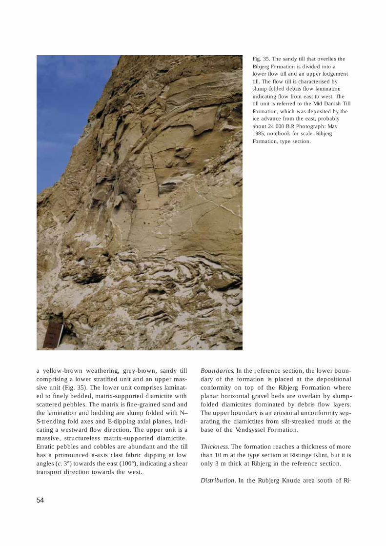
54
a yellow-brown weathering, grey-brown, sandy tillcomprising a lower stratified unit and an upper mas-sive unit (Fig. 35). The lower unit comprises laminat-ed to finely bedded, matrix-supported diamictite withscattered pebbles. The matrix is fine-grained sand andthe lamination and bedding are slump folded with N–S-trending fold axes and E-dipping axial planes, indi-cating a westward flow direction. The upper unit is amassive, structureless matrix-supported diamictite.Erratic pebbles and cobbles are abundant and the tillhas a pronounced a-axis clast fabric dipping at lowangles (c. 3°) towards the east (100°), indicating a sheartransport direction towards the west.
Boundaries. In the reference section, the lower boun-dary of the formation is placed at the depositionalconformity on top of the Ribjerg Formation whereplanar horizontal gravel beds are overlain by slump-folded diamictites dominated by debris flow layers.The upper boundary is an erosional unconformity sep-arating the diamictites from silt-streaked muds at thebase of the Vendsyssel Formation.
Thickness. The formation reaches a thickness of morethan 10 m at the type section at Ristinge Klint, but it isonly 3 m thick at Ribjerg in the reference section.
Distribution. In the Rubjerg Knude area south of Ri-
Fig. 35. The sandy till that overlies the
Ribjerg Formation is divided into alower flow till and an upper lodgement
till. The flow till is characterised byslump-folded debris flow lamination
indicating flow from east to west. Thetill unit is referred to the Mid Danish Till
Formation, which was deposited by theice advance from the east, probably
about 24 000 B.P. Photograph: May1985; notebook for scale. Ribjerg
Formation, type section.

55
bjerg, where the Ribjerg Formation is absent, it hasnot been possible to differentiate occurrences of theMid Danish Till Formation from the older Kattegat TillFormation. However, the distribution is well docu-mented throughout the Danish Basin east and northof the Main Stationary Line (Figs 1, 12; Houmark-Niel-sen 1999, 2003).
Age. The age of the Mid Danish Till Formation isbracketed by the age of the Ribjerg Formation be-neath (26 000 years B.P.) and the Vendsyssel Forma-tion above (16 000 years B.P.) (Fig. 14, Tables 2, 3).The age is estimated to be 24 000 – 20 000 years B.P.(Houmark-Nielsen 2003).
Depositional environment. The lower unit is interpret-ed as a flow till deposited as debris flows from an icemargin to the east, prior to the ice advance towardsthe west. The upper unit is interpreted as a lodge-
ment till deposited at the sole of the ice during the iceadvance from central Sweden towards the Main Sta-tionary Line situated in the central part of the NorthSea (Fig.12).
Vendsyssel Formation
new formation
History. North and south of Rubjerg Knude, the MidDanish Till Formation is overlain by a succession ofglaciomarine heteroliths, which are here defined asthe Vendsyssel Formation. These deposits were map-ped by Jessen (1899), who related them to depositionin the Younger Yoldia Sea in Vendsyssel. Jessen (1918)regarded the various facies of the Vendsyssel Forma-tion as four stratigraphic units named the Lower Saxi-cava Sand, the Yoldia Clay (usually prefaced ‘Young-
Aeolian sand
Vendsyssel Formation
Lønstrup Klint Formationglacitectonite
0 m
5
10
15
sandsiltm.f.si. c.clay
gr. co.
Tectonite
Climbing ripples
Current ripplecross-lamination
Sand
Wave ripple lamination
Lamination
Troughcross-bedding
Gravel
Sandy mud
Clayey mud
Storm sand bed
Bioturbation
Shells
Imbricated mud clasts
Ball-and-pillow convolute bedding
Fig. 36. Sedimentological log of the Vendsyssel Formation at the type section at Stensnæs. The section is located at point 5120 in the
cross-section (Plate 1); the base of the log is 15 m a.s.l.

56
er’ to distinguish it from the Older Yoldia Clay), theUpper Saxicava Sand and the Zirphaea Beds.
Name. The formation is named after the region ofVendsyssel in north Denmark (Figs 12, 13).
Type section. The type section is the coastal cliff sec-tion at Stensnæs c. 1 km north of Nørre Lyngby in thecentral part of the west coast in Vendsyssel (Figs 13, 36).
Reference sections. Two coastal cliff sections, northand south of Rubjerg Knude, are defined as referencesections. The locality to the north is the coastal clif f c.500 m south of Lønstrup, where heteroliths character-ised by Hiatella burrows crop out (Fig. 37). To thesouth, the coastal cliff at Nørre Lyngby (north andsouth of the ramp leading down to the beach) prob-
ably gives the thickest accessible outcrop of the for-mation (Fig. 38). This locality is furthermore close tothe reference well DGU no. 8.137, where the maxi-mum thickness of the formation is recorded (Lykke-Andersen 1987).
Lithology. Two main lithologies dominate the forma-tion: dark bluish-grey, clayey mud in the lower partand yellowish weathering light grey stratified hetero-liths in the upper part. At the base of the formation,coarse-grained sands and gravels overlie the erosion-al unconformity above the Mid Danish Till Formationor older deposits (Figs 36–38). The unit referred to asthe Lower Saxicava Sand by Jessen (1918) is less than2 m thick and is only present locally. Accumulationsof shell debris occur in places. In general, marine clayeymud forms the lower c. 6 m of the formation resting
Tectonite
Basal till
Aeolian sand
Vendsyssel Formation
Kattegat Till Formation
Lønstrup Klint Formationglacitectonite
0 m
5
10
15
Sandy mud
Sand
Gravel
Lamination
Wave ripple lamination
Storm sand bed
Bioturbation
Shells
Troughcross-bedding
Slump structure
Clayey mud
sandm.f.si. c.clay
gr.pb. co.
Fig. 37. Sedimentological log of the Vendsyssel Formation at the reference section, situated halfway between Lønstrup and MårupChurch at point 500 in the cross-section (Plate 1); base of the log is 10 m a.s.l. The slump structure recognised in the lower part of
the section (at about 4 m) is interpreted to have been produced by a grounding iceberg. The abundant shells in the section areHiatella arctica and the bioturbation was due to the infaunal activity of these molluscs (see Fig. 41).
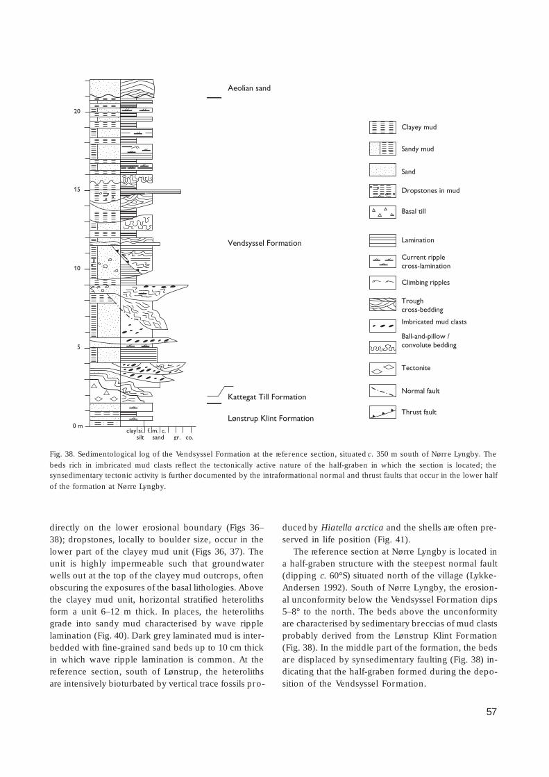
57
directly on the lower erosional boundary (Figs 36–38); dropstones, locally to boulder size, occur in thelower part of the clayey mud unit (Figs 36, 37). Theunit is highly impermeable such that groundwaterwells out at the top of the clayey mud outcrops, oftenobscuring the exposures of the basal lithologies. Abovethe clayey mud unit, horizontal stratified heterolithsform a unit 6–12 m thick. In places, the heterolithsgrade into sandy mud characterised by wave ripplelamination (Fig. 40). Dark grey laminated mud is inter-bedded with fine-grained sand beds up to 10 cm thickin which wave ripple lamination is common. At thereference section, south of Lønstrup, the heterolithsare intensively bioturbated by vertical trace fossils pro-
duced by Hiatella arctica and the shells are often pre-served in life position (Fig. 41).
The reference section at Nørre Lyngby is located ina half-graben structure with the steepest normal fault(dipping c. 60°S) situated north of the village (Lykke-Andersen 1992). South of Nørre Lyngby, the erosion-al unconformity below the Vendsyssel Formation dips5–8° to the north. The beds above the unconformityare characterised by sedimentary breccias of mud clastsprobably derived from the Lønstrup Klint Formation(Fig. 38). In the middle part of the formation, the bedsare displaced by synsedimentary faulting (Fig. 38) in-dicating that the half-graben formed during the depo-sition of the Vendsyssel Formation.
Aeolian sand
Vendsyssel Formation
Kattegat Till Formation
Lønstrup Klint Formation
sandsiltm.f.si. c.clay
gr. co.
0 m
5
10
15
20
Dropstones in mud
Tectonite
Climbing ripples
Current ripplecross-lamination
Basal till
Sandy mud
Sand
Lamination
Troughcross-bedding
Clayey mud
Imbricated mud clasts
Ball-and-pillow / convolute bedding
Normal fault
Thrust fault
Fig. 38. Sedimentological log of the Vendsyssel Formation at the reference section, situated c. 350 m south of Nørre Lyngby. The
beds rich in imbricated mud clasts reflect the tectonically active nature of the half-graben in which the section is located; thesynsedimentary tectonic activity is further documented by the intraformational normal and thrust faults that occur in the lower half
of the formation at Nørre Lyngby.

58
In the area north-east of Hirtshals, the clayey mudis overlain by coastal sands, the so-called Zirphaea Beds(Jessen 1918), and in the eastern part of Vendsysselthe uppermost part of the formation comprises coarse-grained sand and gravel deposited in a large spit sys-tem (Nielsen et al. 1988).
Fossils. The fossils characteristic of the formation arethe molluscs Portlandia arctica, Hiatella arctica andZirphaea crispata.
Boundaries. The lower boundary is the erosional un-conformity on top of the Mid Danish Till Formationor older deposits. The upper boundary is the top sur-face of the landscape upon which locally lie terrestri-al deposits such as the Allerød peat beds in the NørreLyngby bog (Jessen & Nordmann 1915), the Borealpeat at Martørv Bakker (Jessen 1931) and recent aeo-lian sands (Fig. 14).
Thickness. The formation is c. 16 m thick at the out-crops along the coastal cliff. The formation may reach
Fig. 39. Mud-dominated heteroliths in
the lower Vendsyssel Formation. Thelight-coloured silt to very fine-grained
sand beds show grading and waveripple cross-lamination. This unit was
formerly referred to as the YoungerYoldia Clay (Jessen 1918, 1931).
Photograph: September 2004.
Fig. 40. Sand-rich heteroliths in theupper Vendsyssel Formation showing
wave ripple cross-lamination. This sand-rich heterolithic unit was formerly
referred to as the Saxicava Sand (Jessen1918, 1931). Tape divisions in centime-
tres. Photograph: September 2004.

59
a thickness of up to about 25 m in the central part ofVendsyssel (see Fig. 125).
Distribution. The flat agricultural land in the Vendsys-sel area, lying 10–40 m above sea level, defines thetop of the Vendsyssel Formation, and thus can be re-garded to represent the fossil seabed of the YoungerYoldia Sea.
Depositional environment. The formation reflects theestablishment of marine conditions in the Vendsysselarea after the melting back of the Scandinavian IceCap in the Kattegat–Vendsyssel–Skagerrak region. Thepalaeoenvironmental development may be describedin terms of six events (Richard 1996): the first event isrepresented by the erosional unconformity formedimmediately after deglaciation. The second event wasa rapid transgression with the establishment of a c. 60m deep arctic marine environment. In the third event,a high sea-level stand prevailed during deposition ofthe clayey mud. Events four to six are stages of forcedregression due to the isostatic uplift in the area, butwith fluctuations due to eustatic sea-level rise.
Age. The age of the Vendsyssel Formation ranges from17 000 to 14 500 B.P. (Tables 2, 3; Tauber 1966; Krog& Tauber 1974; Knudsen 1978; Abrahamsen & Read-man 1980; Aaris-Sørensen & Petersen 1984; Nielsen etal. 1988; Richard 1996; Houmark-Nielsen 2003).
Fig. 41. At the cliff section north of Mårup Church, the sandymud is often highly bioturbated; in places, the shells of the
bivalve Hiatella arctica are found in life position in the escapetrace fossils. Photograph from the middle part of the section in
Fig. 37. Photograph: September 2004.
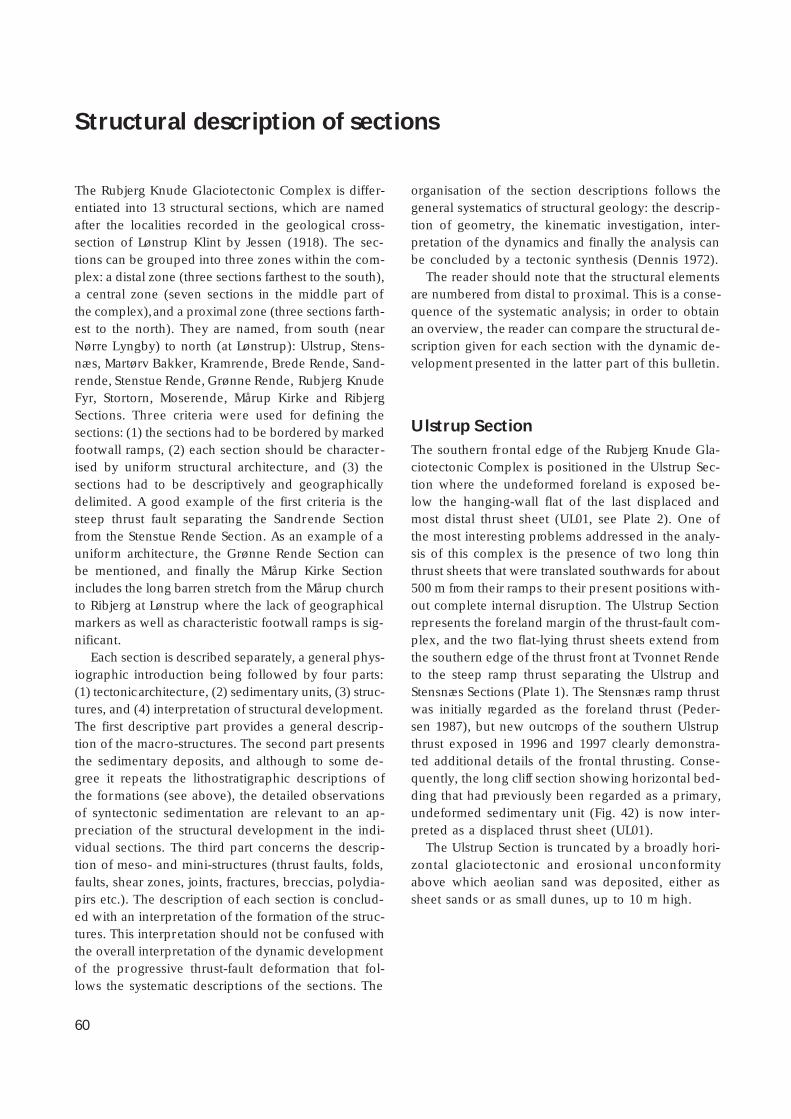
60
Structural description of sections
The Rubjerg Knude Glaciotectonic Complex is differ-entiated into 13 structural sections, which are namedafter the localities recorded in the geological cross-section of Lønstrup Klint by Jessen (1918). The sec-tions can be grouped into three zones within the com-plex: a distal zone (three sections farthest to the south),a central zone (seven sections in the middle part ofthe complex), and a proximal zone (three sections farth-est to the north). They are named, from south (nearNørre Lyngby) to north (at Lønstrup): Ulstrup, Stens-næs, Martørv Bakker, Kramrende, Brede Rende, Sand-rende, Stenstue Rende, Grønne Rende, Rubjerg KnudeFyr, Stortorn, Moserende, Mårup Kirke and RibjergSections. Three criteria were used for defining thesections: (1) the sections had to be bordered by markedfootwall ramps, (2) each section should be character-ised by uniform structural architecture, and (3) thesections had to be descriptively and geographicallydelimited. A good example of the first criteria is thesteep thrust fault separating the Sandrende Sectionfrom the Stenstue Rende Section. As an example of auniform architecture, the Grønne Rende Section canbe mentioned, and finally the Mårup Kirke Sectionincludes the long barren stretch from the Mårup churchto Ribjerg at Lønstrup where the lack of geographicalmarkers as well as characteristic footwall ramps is sig-nificant.
Each section is described separately, a general phys-iographic introduction being followed by four parts:(1) tectonic architecture, (2) sedimentary units, (3) struc-tures, and (4) interpretation of structural development.The first descriptive part provides a general descrip-tion of the macro-structures. The second part presentsthe sedimentary deposits, and although to some de-gree it repeats the lithostratigraphic descriptions ofthe formations (see above), the detailed observationsof syntectonic sedimentation are relevant to an ap-preciation of the structural development in the indi-vidual sections. The third part concerns the descrip-tion of meso- and mini-structures (thrust faults, folds,faults, shear zones, joints, fractures, breccias, polydia-pirs etc.). The description of each section is conclud-ed with an interpretation of the formation of the struc-tures. This interpretation should not be confused withthe overall interpretation of the dynamic developmentof the progressive thrust-fault deformation that fol-lows the systematic descriptions of the sections. The
organisation of the section descriptions follows thegeneral systematics of structural geology: the descrip-tion of geometry, the kinematic investigation, inter-pretation of the dynamics and finally the analysis canbe concluded by a tectonic synthesis (Dennis 1972).
The reader should note that the structural elementsare numbered from distal to proximal. This is a conse-quence of the systematic analysis; in order to obtainan overview, the reader can compare the structural de-scription given for each section with the dynamic de-velopment presented in the latter part of this bulletin.
Ulstrup SectionThe southern frontal edge of the Rubjerg Knude Gla-ciotectonic Complex is positioned in the Ulstrup Sec-tion where the undeformed foreland is exposed be-low the hanging-wall flat of the last displaced andmost distal thrust sheet (UL01, see Plate 2). One ofthe most interesting problems addressed in the analy-sis of this complex is the presence of two long thinthrust sheets that were translated southwards for about500 m from their ramps to their present positions with-out complete internal disruption. The Ulstrup Sectionrepresents the foreland margin of the thrust-fault com-plex, and the two flat-lying thrust sheets extend fromthe southern edge of the thrust front at Tvonnet Rendeto the steep ramp thrust separating the Ulstrup andStensnæs Sections (Plate 1). The Stensnæs ramp thrustwas initially regarded as the foreland thrust (Peder-sen 1987), but new outcrops of the southern Ulstrupthrust exposed in 1996 and 1997 clearly demonstra-ted additional details of the frontal thrusting. Conse-quently, the long cliff section showing horizontal bed-ding that had previously been regarded as a primary,undeformed sedimentary unit (Fig. 42) is now inter-preted as a displaced thrust sheet (UL01).
The Ulstrup Section is truncated by a broadly hori-zontal glaciotectonic and erosional unconformityabove which aeolian sand was deposited, either assheet sands or as small dunes, up to 10 m high.
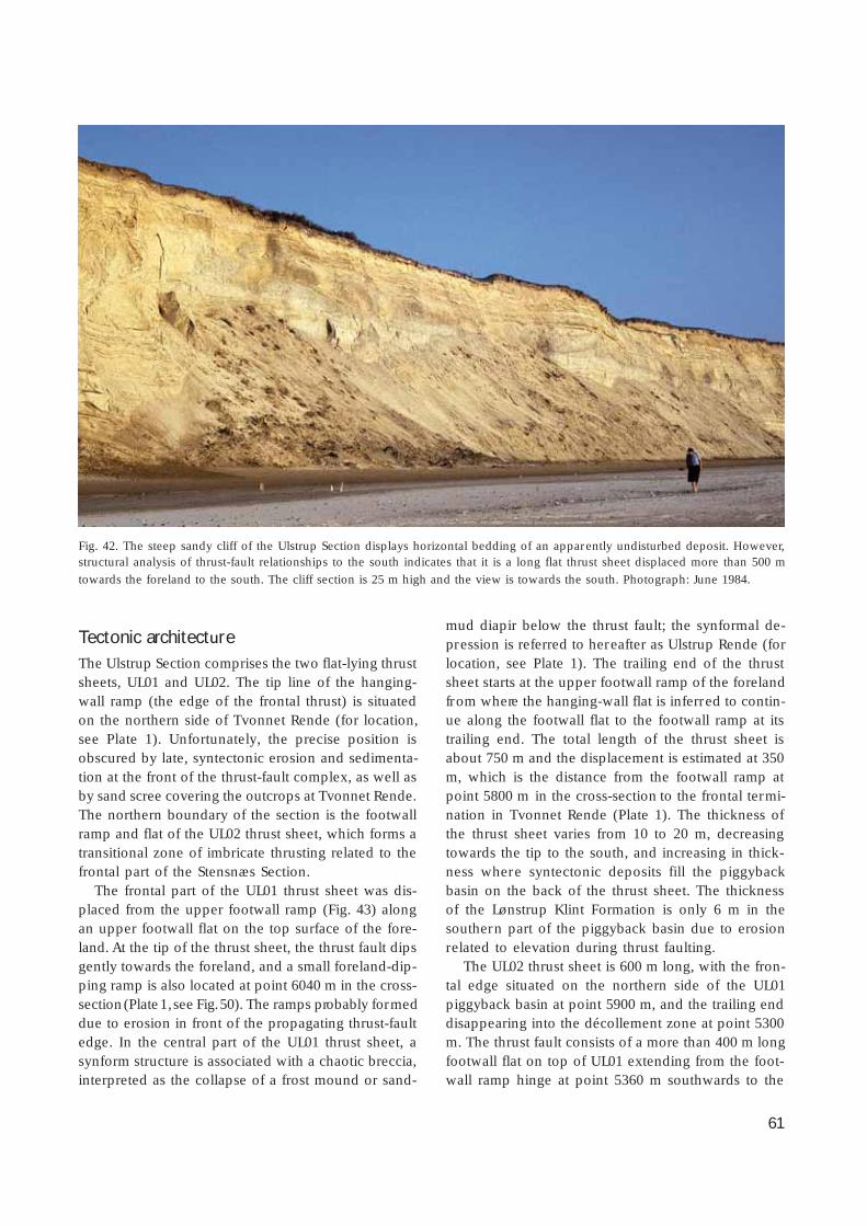
61
Tectonic architectureThe Ulstrup Section comprises the two flat-lying thrustsheets, UL01 and UL02. The tip line of the hanging-wall ramp (the edge of the frontal thrust) is situatedon the northern side of Tvonnet Rende (for location,see Plate 1). Unfortunately, the precise position isobscured by late, syntectonic erosion and sedimenta-tion at the front of the thrust-fault complex, as well asby sand scree covering the outcrops at Tvonnet Rende.The northern boundary of the section is the footwallramp and flat of the UL02 thrust sheet, which forms atransitional zone of imbricate thrusting related to thefrontal part of the Stensnæs Section.
The frontal part of the UL01 thrust sheet was dis-placed from the upper footwall ramp (Fig. 43) alongan upper footwall flat on the top surface of the fore-land. At the tip of the thrust sheet, the thrust fault dipsgently towards the foreland, and a small foreland-dip-ping ramp is also located at point 6040 m in the cross-section (Plate 1, see Fig. 50). The ramps probably formeddue to erosion in front of the propagating thrust-faultedge. In the central part of the UL01 thrust sheet, asynform structure is associated with a chaotic breccia,interpreted as the collapse of a frost mound or sand-
mud diapir below the thrust fault; the synformal de-pression is referred to hereafter as Ulstrup Rende (forlocation, see Plate 1). The trailing end of the thrustsheet starts at the upper footwall ramp of the forelandfrom where the hanging-wall flat is inferred to contin-ue along the footwall flat to the footwall ramp at itstrailing end. The total length of the thrust sheet isabout 750 m and the displacement is estimated at 350m, which is the distance from the footwall ramp atpoint 5800 m in the cross-section to the frontal termi-nation in Tvonnet Rende (Plate 1). The thickness ofthe thrust sheet varies from 10 to 20 m, decreasingtowards the tip to the south, and increasing in thick-ness where syntectonic deposits fill the piggybackbasin on the back of the thrust sheet. The thicknessof the Lønstrup Klint Formation is only 6 m in thesouthern part of the piggyback basin due to erosionrelated to elevation during thrust faulting.
The UL02 thrust sheet is 600 m long, with the fron-tal edge situated on the northern side of the UL01piggyback basin at point 5900 m, and the trailing enddisappearing into the décollement zone at point 5300m. The thrust fault consists of a more than 400 m longfootwall flat on top of UL01 extending from the foot-wall ramp hinge at point 5360 m southwards to the
Fig. 42. The steep sandy cliff of the Ulstrup Section displays horizontal bedding of an apparently undisturbed deposit. However,structural analysis of thrust-fault relationships to the south indicates that it is a long flat thrust sheet displaced more than 500 m
towards the foreland to the south. The cliff section is 25 m high and the view is towards the south. Photograph: June 1984.

62
gently dipping frontal bend at point 5780 m in thecross-section (Plate 1). The frontal bend correspondsto the hinterland-dipping limb of the flat-topped hang-ing-wall anticline of UL01. This hanging-wall anticlinecompares well with the structure of the thrust-faultmodel in Fig. 6, and the southernmost c. 100 m ofUL02 can be regarded to have been emplaced piggy-back on UL01 during the translation over the frontalfootwall ramp. The UL02 thrust sheet is only 5–6 mthick above the flat-topped anticline, whereas the thick-ness increases to 20 m at the trailing-end ramp. Thedisplacement along the northern thrust fault is 550 m,with an uncertainty of 10–25 m depending on the in-terpretation of the shape of the trailing-end ramp andthe amount of erosion of the frontal part at the piggy-back basin at Ulstrup Rende.
Sedimentary unitsThe sedimentary units in the Ulstrup Section comprisethe upper part of the Lønstrup Klint Formation, ero-sional remnants of the lower part of the Rubjerg Knu-de Formation, and a variety of intercalations of theRubjerg Knude Formation distinguished here as the
Ulstrup beds. The L/R-unconformity between the Løn-strup Klint and Rubjerg Knude Formations can betraced along the upper part of the UL01 thrust sheetin which it also forms the base of the piggyback ba-sin. A few younger erosional unconformities, belowand above the Ulstrup beds, are of only local signifi-cance within the Ulstrup Section.
Lønstrup Klint Formation
The mud-dominated Lønstrup Klint Formation formsthe main part of the thrust sheets in the Ulstrup Sec-tion, and has an average thickness of about 10 m (Fig.19). In the southern thrust sheet, the fine-grained sandbeds are thin and only small-scale current ripples havebeen observed. A combination of load structures (ball-and-pillow) and water-escape structures (convolutionand small-scale diapirs) are developed at certain hori-zons. Above the hanging-wall flat, a zone about 2 mthick takes the form of a mobilised mud breccia, whichcan be characterised as a sole thrust zone. This brec-cia is superimposed by beds affected by a brittle typeof brecciation, forming cracks and joints in an up to 4m thick zone in the lower part of the thrust sheet.
Fig. 43. The upper footwall ramp of the foreland (Foreland FWR) along which the UL01 thrust fault propagated (UL01HWF: Ulstrupthrust sheet 01 hanging-wall flat), and from where it continued for more than 300 m over the footwall flat of the foreland. The clif f
section is 25 m high and south is to the right. Photograph: May 1998.

63
The northern thrust sheet (UL02) displays a moresandy part of the Lønstrup Klint Formation (Fig. 25).Here the sand beds are up to 1 m thick and water-escape structures, convolute bedding and flame struc-tures commonly disturb the primary bedding. Ball-and-pillow structures are more common towards thetrailing end of the thrust sheets.
Rubjerg Knude Formation
In the Ulstrup Section, the Rubjerg Knude Formationcomprises three different depositional units: the main‘background’ sedimentation of outwash sand, the gla-ciolacustrine Ulstrup beds (Fig. 25), and the coarse-grained glaciofluvial Ulstrup beds (Fig. 20).
The main depositional unit is fine- to medium-grained meltwater sand represented in the footwallblock of the foreland (Fig. 43). Small-scale current rip-ples occur in the parallel bedded sand, which is inter-layered with c. 0.5 m thick trough cross-stratified beds.
The glaciolacustrine Ulstrup beds form a 3–5 m thickunit that is only found on the back of the UL02 thrustsheet (Fig. 25). This unit consists of dark bluish grey,laminated clayey mud interlayered with a few sandybeds up to 0.5 m in thickness. The unit was depositedon a bedding-parallel unconformity, which is onlydiscordantly developed in the northernmost trailingpart of thrust sheet UL02. The unit thins out towardsthe south, and disappears near the hinterland-dippinglimb of the flat-topped hanging-wall anticline formedabove the footwall ramp of the foreland. Intraforma-
Fig. 44. The mud-mobilised thrust-zone
breccia consists of structureless mudwith scattered clasts floating in the
matrix. Dilation cracks filled with sandare superimposed on the mud-mobilised
brecciation fabric. This reflects twophase of cataclastic deformation: a first
phase of water-over-pressured breccia-tion (hydrodynamic brecciation), and a
second phase of brittle fracturing whenthe mud was consolidated, dehydrated
or perhaps frozen. Handle of spade is12 cm. Photograph: June 1997.
tional hydrodynamic brecciation, including small-scalediapirs and slump-like features, deformed the clayeymud; such deformation is not seen in the LønstrupKlint Formation below the unit.
The glaciofluvial Ulstrup beds occur in the UlstrupRende depression between points 5900 and 6000 min the cross-section (Plate 1). This unit is a c. 8 mthick succession of meltwater gravel fining up intocoarse-grained sand (Fig. 20). Large-scale trough cross-bedding dominates the succession and clasts up toboulder size occur in the lowermost 2 m (Fig. 28).Lithologically, the clasts are dominated by flint, butclasts of fossil frozen sand are abundant (Fig. 29).
The glaciofluvial Ulstrup beds are overlain by c. 5m of medium- to coarse-grained sand of the RubjergKnude Formation. On the north side of the UlstrupRende depression, between points 5900 and 6000 m,slump-folded sand beds and sedimentary brecciasoccur in the upper part of this succession, suggestinggravity gliding down the steep slope of the depres-sion (piggyback basin of UL01).
Structures and brecciasThe most important structures related to the thrustfaults in the Ulstrup Section are the breccias occurringin the thrust zones above the thrust-fault surfaces. Theyappear to have formed by collapse of the thrust sheetduring translation. The low-angle anastomosing faultsthat developed in the most distal part of the thrust-fault complex originated similarly during translation
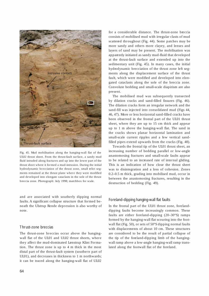
64
and are associated with southerly dipping normalfaults. A significant collapse structure that formed be-neath the Ulstrup Rende depression is also worthy ofnote.
Thrust-zone breccias
The thrust-zone breccias occur above the hanging-wall flat of the UL01 and UL02 thrust sheets, wherethey affect the mud-dominated Lønstrup Klint Forma-tion. The thrust zone is up to 4 m thick in the mostdistal part of the thrust-fault system (southern part ofUL01), and decreases in thickness to 1 m northwards;it can be traced along the hanging-wall flat of UL02
for a considerable distance. The thrust-zone brecciaconsists of mobilised mud with irregular clasts of mudscattered throughout (Fig. 44). Some patches may bemore sandy and others more clayey, and lenses andlayers of sand may be present. The mobilisation wasapparently initiated as sandy mud-fluid that developedat the thrust-fault surface and extended up into thesedimentary unit (Fig. 45). In many cases, the initialhydrodynamic brecciation of the thrust zone left seg-ments along the displacement surface of the thrustfault, which were modified and developed into elon-gated cataclasts along the sole of the breccia zone.Convolute bedding and small-scale diapirism are alsopresent.
The mobilised mud was subsequently transectedby dilation cracks and sand-filled fissures (Fig. 46).The dilation cracks form an irregular network and thesand-fill was injected into consolidated mud (Figs 44,46, 47). More or less horizontal sand-filled cracks havebeen observed in the frontal part of the UL01 thrustsheet, where they are up to 15 cm thick and appearup to 1 m above the hanging-wall flat. The sand inthe cracks shows planar horizontal lamination andsmall-scale current ripples and a few vertical sand-filled pipes extend upwards from the cracks (Fig. 48).
Towards the frontal tip of the UL01 thrust sheet, anincreasing number of bedding parallel or low-angleanastomosing fractures and small-scale faults appearto be related to an increased rate of internal gliding.This is an indication of how close the thrust sheetwas to disintegration and a loss of cohesion. Zones0.2–0.5 m thick, grading into mobilised mud, occur inbetween the anastomosing fractures, resulting in thedestruction of bedding (Fig. 49).
Foreland-dipping hanging-wall flat faults
In the frontal part of the UL01 thrust zone, foreland-dipping faults become increasingly common. Thesefaults are either foreland-dipping (20–30°S) rampsformed by the hanging-wall flat scouring into the foot-wall flat (Fig. 50), or sets of 50°S dipping normal faultswith displacements of about 10 cm. These structuresare considered to be the result of partial collapse ofthe tip of the foreland-dipping limb of the hanging-wall ramp above a low-angle hanging-wall ramp trans-lated along the footwall flat of the foreland.
Intrusive contact
Thrust-fault surface
Fig. 45. Mud mobilisation along the hanging-wall flat of the
UL02 thrust sheet. From the thrust-fault sur face, a sandy mudfluid intruded along fractures and up into the lower part of the
thrust sheet where it formed a mud-intrusion. During the initialhydrodynamic brecciation of the thrust zone, small relict seg-
ments remained at the thrust plane where they were modifiedand developed into elongate cataclasts in the sole of the thrust
breccia zone. Photograph: July 1998; matchbox for scale.
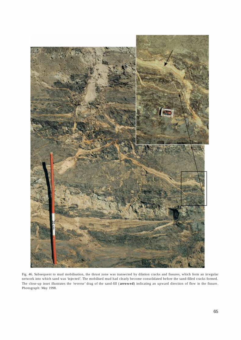
65
Fig. 46. Subsequent to mud mobilisation, the thrust zone was transected by dilation cracks and fissures, which form an irregularnetwork into which sand was ‘injected’. The mobilised mud had clearly become consolidated before the sand-filled cracks formed.
The close-up inset illustrates the ‘reverse’ drag of the sand-fill (arrowed) indicating an upward direction of flow in the fissure.Photograph: May 1998.

66
Collapse structure in the Ulstrup Rende
Structures in the central part of Ulstrup Rende (Figs51, 52) are interpreted to represent a collapsed diapir.The early phase structures include thinning of the Løn-strup Klint Formation in the thrust sheet, and forma-tion of concave troughs in its surface. Vertically orsteeply dipping sand breccias with upward directedflow structures cross-cut the thrust-zone breccia. Theappearance of structureless sand pockets indicates sand-fill of mobilised sediment from an over-pressured zonein the subsurface. The complex of breccias and re-orientated bedding is interpreted as a collapse struc-ture; it is considered to be responsible for the forma-tion of the Ulstrup Rende depression, and the disrup-tion of the thrust sheet along steeply dipping frac-tures. In the breccia zone, steeply dipping sand-filledcracks and normal faults formed prior to the contin-ued deposition of the Rubjerg Knude Formation inthe depression.
On the southern side of the Ulstrup Rende depres-sion, the muddy part of the thrust sheet is displacedby steeply dipping normal faults. Downthrow is to thesouth, synthetic towards the depression, and the faultsare thought to be related to the collapse of the diapirstructure.
Interpretation of structural developmentThere are two reasons why the Ulstrup Section de-serves special attention. The first is that it represents aforeland thrust section with long lateral transport ofthin thrust sheets, the nature of which has not previ-ously been documented. Secondly, it demonstratesthe likely development of the initial stages of defor-mation, which the remainder of the thin-skinned thrustfaulting in the Rubjerg Knude Glaciotectonic Com-plex also experienced before the uppermost part waseroded. Thus the first phase of thrust-fault deforma-tion is preserved here whereas it is almost never re-presented in the thrust-fault sections that have been
Fig. 47. The formation of thrust-zone breccias in the distal part of the thrust-fault complex is here illustrated in four stages ofdevelopment. (1) The initial undeformed sediment (Lønstrup Klint Formation) comprises clayey mud interlayered with thin sand
beds. (2) A mud-fluid is formed above the thrust-fault surface (line with open triangles ) from where it is injected up into the layersabove (see Fig. 45). (3) Increasing mud-mobilisation results in the formation of a structureless matrix with dispersed matrix-
supported clasts of the primary sediment (see Fig. 44). Note the small normal faults indicating an on-going process of collapse. (4)The mobilised mud becomes consolidated and the thrust-zone breccia develops into a more brittle stage; dilation cracks form into
which water-saturated sand is injected (see Fig. 46).

67
more intensely deformed. The interpretation of thestructural development can be summarised in the fol-lowing nine stages.
1. Initial thrust-fault fracturing and thrust-fault propa-gation took place during mobilisation of mud alongthe hanging-wall flat. At this stage, the thrust-zonebreccia was formed due to high pore-water pres-sure in an unfrozen stage.
2. The UL01 and UL02 thrust sheets probably startedto move along the décollement zone as one coher-ent thrust sheet, and first separated into two thrust
sheets after the frontal part of the sheet had passedthe most distal foreland footwall ramp.
3. The ramping up of the northern UL02 thrust sheetprobably increased the pore-water pressure, andwhen this increase also affected the frontal part ofUL01, diapirism was initiated under the central partof the southern thrust sheet.
4. The diapiric uplift and erosion took place in theelevated surface. This erosion extended through theRubjerg Knude Formation to locally intersect theL/R-unconformity. The residual coarse clastic gravel
Fig. 48. A subhorizontal sand-filled
fracture occurring in the frontal part ofthe UL01 thrust sheet. The sand-filled
fracture appears about 1 m above thehanging-wall flat; the sand shows planar
horizontal lamination and current ripplecross-lamination. The sand-filled fracture
is interpreted to have formed duringground-frozen conditions, whereas the
vertical sand-filled pipe probably reflectsloading of the thrust sheet when it
ultimately lost its carrying pore-waterpressure and settled on its hanging-wall
flat. Photograph: June 1997.
Fig. 49. Subhorizontal anastomosing
faulting (centre left) with mud-mobilisa-tion developed in domains between
fault fractures in the frontal part of theUL01 thrust sheet. Photograph: June
1997.

68
Fig. 50. A: Foreland-dipping ramping of hanging-wall flatformed by scouring-erosion of the footwall flat into the
top surface of the foreland. Note in the close-up (B) thatsome hydrodynamic brecciation occurred in the footwall
ramp just below the thrust zone. Photograph: June 1997.
on the footwall flat at the surface of the forelandin the Ulstrup Section.
7. The consequence of the diapir collapse was theformation of the depression in Ulstrup Rende.Redeposited coarse-grained clastic material filledthe depression, generating the glaciofluvial Ul-strup beds. The occurrence of fossil frozen-sandclasts implies that part of the surface, the Ru-bjerg Knude Formation, was ground-frozen –probably that part of the thrust sheet that hadbeen elevated due to the propagation up overthe central ramp. The ground-frozen conditionwas probably also responsible for freezing ofthe mobilised mud in the thrust zone and thesubsequent development of sand-filled dilationcracks (Fig. 47)
bed on the unconformity surface was probably the orig-inal source for the large amount of coarse-grained ma-terial in the Ulstrup Rende depression.
5. The mud-sand volcano broke through to the surface, andthe mobilised mud and sand were extruded with therelease of the high pore-water pressure.
6. The surface of the diapir collapsed and gravel and sandfilled the fractured structure. The collapse was probablycontemporaneous with the loss of pore pressure through-out the thrust zone. The release of over-pressure in thethrust zone resulted in the final settling of the thrust sheet
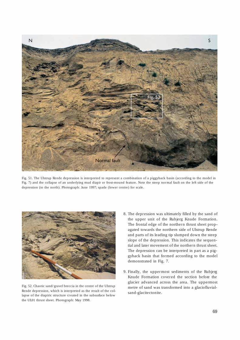
69
8. The depression was ultimately filled by the sand ofthe upper unit of the Rubjerg Knude Formation.The frontal edge of the northern thrust sheet prop-agated towards the northern side of Ulstrup Rendeand parts of its leading tip slumped down the steepslope of the depression. This indicates the sequen-tial and later movement of the northern thrust sheet.The depression can be interpreted in part as a pig-gyback basin that formed according to the modeldemonstrated in Fig. 7.
9. Finally, the uppermost sediments of the RubjergKnude Formation covered the section before theglacier advanced across the area. The uppermostmetre of sand was transformed into a glaciofluvial-sand-glacitectonite.
Fig. 51. The Ulstrup Rende depression is interpreted to represent a combination of a piggyback basin (according to the model inFig. 7) and the collapse of an underlying mud diapir or frost-mound feature. Note the steep normal fault on the left side of the
depression (to the north). Photograph: June 1997; spade (lower centre) for scale.
Fig. 52. Chaotic sand/gravel breccia in the centre of the Ulstrup
Rende depression, which is interpreted as the result of the col-lapse of the diapiric structure created in the subsurface below
the UL01 thrust sheet. Photograph: May 1998.

70
Stensnæs SectionThe Stensnæs Section is named after Stensnæs, whichis a minor point (Danish: sten = stone; næs (pynt) =point) at a gentle bend in the cliff section. Stones anderratic blocks, probably derived from the up to 2 mthick sandy till and the erosional unconformity belowthe Vendsyssel Formation, were formerly abundanton this part of the beach. The sandy till thins out south-wards where a glaciotectonic unconformity truncatesthe section.
The Stensnæs Section displays the most spectacu-lar folds in the Rubjerg Knude Glaciotectonic Com-plex (Fig. 53). The folds are situated at the transitionfrom the flat-lying beds to the south (the Ulstrup Sec-tion) and the main thrust-fault imbrications to thenorth. The fold complex is truncated by an erosionalunconformity forming a depression in which slumpslides and sedimentary breccias derived from the tipof the thrust sheet were deposited after collapse andgravity gliding. In general, the fold complex is wellexposed, whereas the transition further southwards isoften covered by sand scree. During the years of studyof the Rubjerg Knude Glaciotectonic Complex by theauthor, variations in the degree of exposure of theStensnæs Section have contributed to a fuller under-
standing of the structural development of the sectionthat represents the foreland margin of the thrust-faultcomplex.
Tectonic architectureThe Stensnæs Section comprises four thrust sheets(SN01, SN02, SN03 and SN04, Plate 2). The southernboundary of the section is defined by the footwallramp of UL02, although the trailing end of UL02 ishere included in the description of the imbricate du-plex that hosts the fold complex. The northern boun-dary is the hanging-wall ramp of MB01/MB02, that isthrust up along the footwall block of SN04. The thrustsheets comprise the uppermost part of the LønstrupKlint Formation and a relatively thin cover of the over-lying Rubjerg Knude Formation sediments. Two dis-crete piggyback basins (early and late) were formedabove the SN01 and SN02 thrust sheets.
The SN01 thrust sheet is about 30 m thick, and al-though the thrust sheet includes a number of smallduplex imbricates it can be subdivided into upper andlower segments. The lower segment is thrust onto theUL02
footwall
block
with
a
displacement
of
about
30 m.
The displacement of the upper segment is partitioned
Fig. 53. The fold complex developed in the transitional imbricate zone between Ulstrup and Stensnæs Sections. Note that the thrust
faults acting as flexural slip surfaces in the folding continue into the bedding-parallel thrust-fault flats to the south (right). Photo-graph: July 2000.

71
into a series of minor dif ferential displacements rang-ing from minor flexural slips along bedding surfaces inthe fold structures to imbricate offsets of about 1–3 m.
In the frontal part of the SN02 thrust sheet, the Løn-strup Klint Formation is only a few metres thick, andis overlain by 10 m of sediments of the Rubjerg Knu-de Formation resting on the L/R-unconformity. At thetrailing end of the thrust sheet, the Lønstrup Klint For-mation is more than 15 m thick, whereas the RubjergKnude Formation is cut off by the footwall ramp ofSN02 (corresponding to the hanging-wall thrust fault
for the imbricates of SN03). The accumulated displace-ment of SN02 amounts to 88 m, including 15 m upover the footwall ramp and 73 m along the footwallflat of SN01.
The SN03 thrust sheet may be divided into fourimbricate segments thrust onto the footwall ramp ofSN02. The displacement along the hanging-wall thrustfault is 45 m, but it was also carried piggyback onSN02 during the translation along the décollementzone, which gives an accumulated displacement of163 m for the SN03 thrust sheet.
Fig. 54. Ball-and-pillow structures in the
Lønstrup Klint Formation in the Stens-næs Section. Note that the size of the
structures reflects the thickness of thesand beds involved. Photograph: July
2000; staff divisions are 20 cm.
Fig. 55. Dish-and-pillar structuresdeveloped in the lowermost sandy bed
above the hanging-wall flat of the SN2thrust sheet in the Stensnæs Section.
This type of water-escape structure isinterpreted to have formed during the
thrust-fault translation along a hanging-wall flat due to the high water pressure
released from the sole of the thrust
sheet. Photograph: July 1998.

72
The SN04 thrust sheet is about 20 m thick, includ-ing an up to 8 m thick unit of the Rubjerg KnudeFormation resting on the L/R-unconformity above theLønstrup Klint Formation; this unit increases in thick-ness to about 15 m towards the trailing end of SN04.Total displacement is about 45 m, including a hang-ing-wall ramp-and-flat propagation along the footwallramp of SN03.
Sedimentary unitsThe sedimentary units that crop out in the StensnæsSection are dominated by the upper sandy parts ofthe Lønstrup Klint Formation. A lens of a glaciolacust-rine diamictite is preserved as an imbricate thrust sheet,c. 3.5 m thick and 22 m long, and is tentatively inter-preted to form part of the Rubjerg Knude Formation.The latter is mainly represented by a 6–8 m thick suc-cession including the residual gravel deposited on theuneven surface of the L/R-unconformity. An upperunconformity truncates the SN01 and SN02 thrustsheets, and coarse gravel beds as well as olistoliths ofthe Lønstrup Klint Formation were deposited in a latepiggyback basin (SnstRu in Plate 2).
Lønstrup Klint Formation
The sedimentology of the Lønstrup Klint Formationin the Stensnæs Section is similar to that described forthe Ulstrup Section. The maximum thickness of theformation is about 15 m, and lithologies are dominatedby 0.2–0.8 m thick fine-grained sand beds with climb-ing ripple lamination. Thin laminae of mud and smallamounts of detrital organic material commonly drapethe ripples. The sand beds are interlayered with thinlaminated dark grey mud beds; micro-faulting is evi-dent in this facies. Ball-and-pillow and convolute struc-tures are abundant (Fig. 54). In the uppermost 4 m ofthe formation, the sandy beds become thinner andthe uppermost part is dominated by mud. In sand bedsinferred to be situated above the hanging-wall flat,dish-and-pillar structures have been observed (Fig. 55)that are interpreted to have formed by water-escapeprocesses related to the thrusting.
Cheel & Rust (1986) provided a model for the de-velopment of water-escape structures in glacial out-wash deposits from Ottawa, Canada. In their model, asequential development from simple load structuresthrough detached ball-and-pillow structures to dishstructures is demonstrated. The model predicts a stra-
Fig. 56. The piggyback basin situated above the erosional truncation of thrust sheet UL02 and SN01 in the Stensnæs Section (SNstRuin Plate 2). Note that normal listric faults (arrow) may be traced to the trailing end of the large olistoliths (green) deposited in the
meltwater sand and gravel. This is interpreted as the result of gravity gliding of the tip of a thrust sheet, which during propagationfrom the north collapsed subsequent to thrust faulting up above the mean level of sedimentation. Photograph: July 2000; thrusts
indicated in red, unconformity indicated in purple .
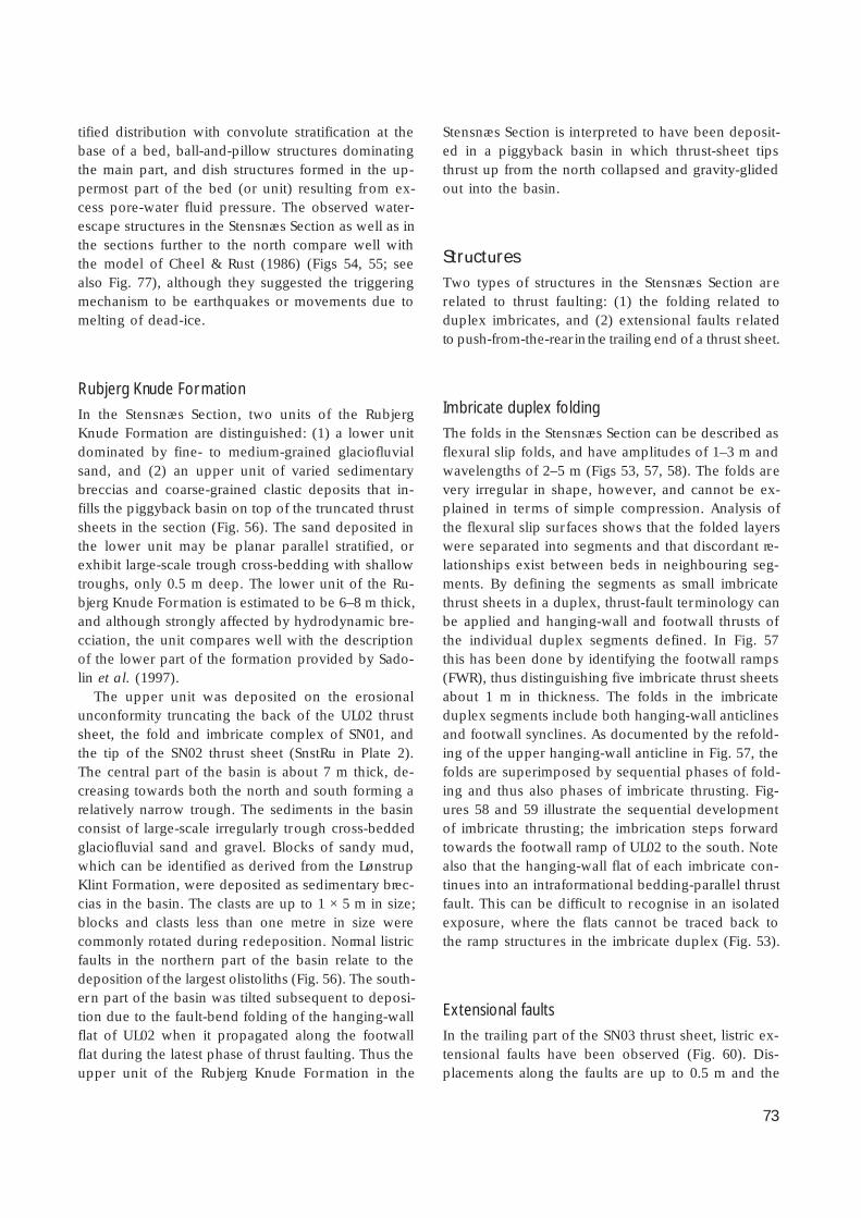
73
tified distribution with convolute stratification at thebase of a bed, ball-and-pillow structures dominatingthe main part, and dish structures formed in the up-permost part of the bed (or unit) resulting from ex-cess pore-water fluid pressure. The observed water-escape structures in the Stensnæs Section as well as inthe sections further to the north compare well withthe model of Cheel & Rust (1986) (Figs 54, 55; seealso Fig. 77), although they suggested the triggeringmechanism to be earthquakes or movements due tomelting of dead-ice.
Rubjerg Knude Formation
In the Stensnæs Section, two units of the RubjergKnude Formation are distinguished: (1) a lower unitdominated by fine- to medium-grained glaciofluvialsand, and (2) an upper unit of varied sedimentarybreccias and coarse-grained clastic deposits that in-fills the piggyback basin on top of the truncated thrustsheets in the section (Fig. 56). The sand deposited inthe lower unit may be planar parallel stratified, orexhibit large-scale trough cross-bedding with shallowtroughs, only 0.5 m deep. The lower unit of the Ru-bjerg Knude Formation is estimated to be 6–8 m thick,and although strongly affected by hydrodynamic bre-cciation, the unit compares well with the descriptionof the lower part of the formation provided by Sado-lin et al. (1997).
The upper unit was deposited on the erosionalunconformity truncating the back of the UL02 thrustsheet, the fold and imbricate complex of SN01, andthe tip of the SN02 thrust sheet (SnstRu in Plate 2).The central part of the basin is about 7 m thick, de-creasing towards both the north and south forming arelatively narrow trough. The sediments in the basinconsist of large-scale irregularly trough cross-beddedglaciofluvial sand and gravel. Blocks of sandy mud,which can be identified as derived from the LønstrupKlint Formation, were deposited as sedimentary brec-cias in the basin. The clasts are up to 1 × 5 m in size;blocks and clasts less than one metre in size werecommonly rotated during redeposition. Normal listricfaults in the northern part of the basin relate to thedeposition of the largest olistoliths (Fig. 56). The south-ern part of the basin was tilted subsequent to deposi-tion due to the fault-bend folding of the hanging-wallflat of UL02 when it propagated along the footwallflat during the latest phase of thrust faulting. Thus theupper unit of the Rubjerg Knude Formation in the
Stensnæs Section is interpreted to have been deposit-ed in a piggyback basin in which thrust-sheet tipsthrust up from the north collapsed and gravity-glidedout into the basin.
StructuresTwo types of structures in the Stensnæs Section arerelated to thrust faulting: (1) the folding related toduplex imbricates, and (2) extensional faults relatedto push-from-the-rear in the trailing end of a thrust sheet.
Imbricate duplex folding
The folds in the Stensnæs Section can be described asflexural slip folds, and have amplitudes of 1–3 m andwavelengths of 2–5 m (Figs 53, 57, 58). The folds arevery irregular in shape, however, and cannot be ex-plained in terms of simple compression. Analysis ofthe flexural slip surfaces shows that the folded layerswere separated into segments and that discordant re-lationships exist between beds in neighbouring seg-ments. By defining the segments as small imbricatethrust sheets in a duplex, thrust-fault terminology canbe applied and hanging-wall and footwall thrusts ofthe individual duplex segments defined. In Fig. 57this has been done by identifying the footwall ramps(FWR), thus distinguishing five imbricate thrust sheetsabout 1 m in thickness. The folds in the imbricateduplex segments include both hanging-wall anticlinesand footwall synclines. As documented by the refold-ing of the upper hanging-wall anticline in Fig. 57, thefolds are superimposed by sequential phases of fold-ing and thus also phases of imbricate thrusting. Fig-ures 58 and 59 illustrate the sequential developmentof imbricate thrusting; the imbrication steps forwardtowards the footwall ramp of UL02 to the south. Notealso that the hanging-wall flat of each imbricate con-tinues into an intraformational bedding-parallel thrustfault. This can be difficult to recognise in an isolatedexposure, where the flats cannot be traced back tothe ramp structures in the imbricate duplex (Fig. 53).
Extensional faults
In the trailing part of the SN03 thrust sheet, listric ex-tensional faults have been observed (Fig. 60). Dis-placements along the faults are up to 0.5 m and the

74
Fig. 57. Flexural slip folding in the sandy beds of the LønstrupKlint Formation in the Stensnæs Section. Numbers (1–4) refer
to the sequential development of the thrust faults in the duplexstructure, which probably formed during the collapse of the
footwall ramp to the south (UL02FWR). Note that the rampthrust faults propagate into bedding-parallel flats. Photograph:
May 1996.
Fig. 58. Detail of the fold structures formed by superimposed
ramp propagation (see Fig. 57). The thrust-fault segments inthe imbricate duplex are marked by black lines and the
recognised footwall ramps are annotated FWR. Hanging-wallanticlines are dominant, but footwall synclines also add to the
fold framework. Photograph: May 1996.
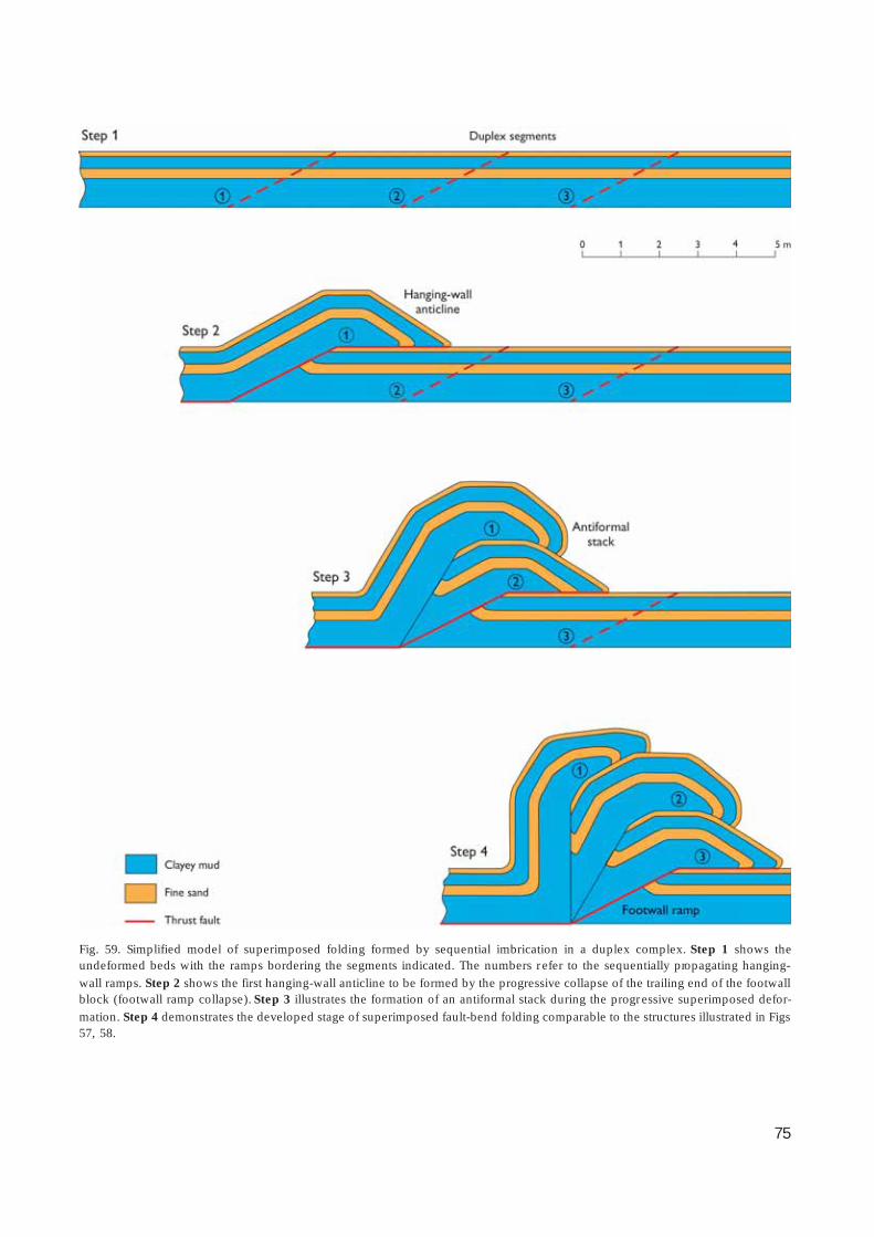
75
Fig. 59. Simplified model of superimposed folding formed by sequential imbrication in a duplex complex. Step 1 shows theundeformed beds with the ramps bordering the segments indicated. The numbers refer to the sequentially propagating hanging-
wall ramps. Step 2 shows the first hanging-wall anticline to be formed by the progressive collapse of the trailing end of the footwallblock (footwall ramp collapse). Step 3 illustrates the formation of an antiformal stack during the progressive superimposed defor-
mation. Step 4 demonstrates the developed stage of superimposed fault-bend folding comparable to the structures illustrated in Figs57, 58.

76
Fig. 60. Low-angle listric extensional faults in the SN03 thrust sheet, in the central part of the Stensnæs Complex. A: An overview ofthe macroscopic structure, where the SN04 thrust sheet ramps up along the footwall flat of SN03 and pushes it laterally in the back.
The resultant extensional fault imbricates form a boudinage-like network. B: Detail of the listric extensional faults (arrows) inter-preted to have been formed by push-from-the-rear. Photograph: July 1996; staf f divisions are 20 cm.

77
Fig. 61. Illustration of the difference between the mild deformation af fecting the top of the footwall block and the strong defor-
mation of the hanging-wall block. Only a 20 cm thick zone below the shear-laminated thrust-fault surface was affected by low-angleextensional faulting grading down into a minor normal fault network. It is thus evident that the elevated water pressures supporting
the thrust sheet were transmitted to the hanging-wall flat, where intense hydrodynamic brecciation took place. Photograph: July1998.
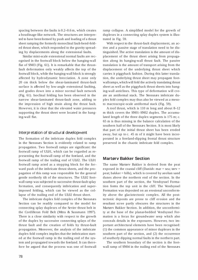
78
spacing between the faults is 0.2–0.6 m, which createsa boudinage-like network. The structures are interpre-ted to have been formed by push and loading of a thrustsheet ramping the formerly monoclinal fault-bend-fold-ed thrust sheet, which responded to the gravity spread-ing by displacements along the extensional faults.
Similar mini-scale extensional normal faults are rec-ognised in the footwall block below the hanging-wallflat of SN03 (Fig. 61). It is remarkable that the thrust-fault deformation only weakly affects the top of thefootwall block, while the hanging-wall block is stronglyaffected by hydrodynamic brecciation. A zone only20 cm thick below the shear-laminated thrust-faultsurface is affected by low-angle extensional faulting,and grades down into a minor normal fault network(Fig. 61). Isoclinal folding has been observed in thenarrow shear-laminated thrust-fault zone, adding tothe impression of high strain along the thrust fault.However, it is clear that the elevated water pressuressupporting the thrust sheet were located in the hang-ing-wall flat.
Interpretation of structural developmentThe formation of the imbricate duplex fold complexin the Stensnæs Section is evidently related to ramppropagation. Two footwall ramps are significant: thefootwall ramp of UL01, which can be regarded as re-presenting the footwall ramp of the foreland, and thefootwall ramp of the trailing end of UL02. The UL01footwall ramp acted as a stopping block for the for-ward push of the imbricate thrust sheets, and the pro-pagation of this ramp was responsible for the generalgentle northerly tilt of the structures. The UL02 foot-wall ramp was subjected to successive thrust-fault splayformation, and consequently imbrication and super-imposed folding, which can be viewed as the col-lapse of the trailing end of the UL02 thrust sheet.
The imbricate duplex fold complex of the StensnæsSection can be readily compared to the model forconnecting splay duplexes of the Sevier thrust belt inthe Cordilleran Fold Belt (Mitra & Sussmann 1997).There is a close similarity with respect to the growthof the duplex by successive connecting splays of thethrust fault and the creation of folds by thrust-faultpropagation. Moreover, the analysis of the imbricateduplex fold complex implies that the imbrication start-ed at the footwall ramp in the trailing end of the sys-tem and propagated towards the foreland. It can there-fore be argued that the process was one of footwall
ramp collapse. A simplified model for the growth ofduplexes in a connecting splay duplex system is illus-trated in Fig. 59.
With respect to the thrust-fault displacement, an ac-tive and a passive stage of translation need to be dis-tinguished. The active translation is the amount of dis-placement of the thrust sheet arising from propaga-tion along its hanging-wall thrust fault. The passivetranslation is the amount of transport arising from thedisplacement of the underlying thrust sheet whichcarries it piggyback fashion. During this latter transla-tion, the underlying thrust sheet may propagate foot-wall ramps, which will fold the actively translating thrustsheet as well as the piggyback thrust sheets into hang-ing-wall anticlines. This type of deformation will cre-ate an antiformal stack. The Stensnæs imbricate du-plex fold complex may thus also be viewed as a meso-to macroscopic-scale antiformal stack (Fig. 59).
A roof thrust, which is 110 m long and about 8–12m thick covers the SN01–SN02 duplex. The accumu-lated length of the three duplex segments is 175 m; c.65 m is thus missing in the balance calculation of thesouthern half of the Stensnæs Section. It is most likelythat part of the initial thrust sheet has been erodedaway, but up to c. 45 m of it might have been incor-porated in a foreland-dipping frontal thrust structurepreserved in the chaotic imbricate fold complex.
Martørv Bakker SectionThe name Martørv Bakker is derived from the peatexposed in the coastal cliff (Danish: mar = sea; tørv =peat; bakker = hills), which is covered by aeolian sanddunes above the northern end of the section. In thesouthern part of the section, the Vendsyssel Forma-tion forms the top unit in the clif f. The VendsysselFormation was deposited on an erosional unconform-ity above the glaciotectonic complex. All the post-tectonic deposits are prone to cliff erosion and theresultant scree partly obscures the structures in theMartørv Bakker Section. In addition, the unconformi-ty at the base of the planar-bedded Vendsyssel For-mation is a focus for groundwater seep which alsoconceals details in the exposures. However, two im-portant architectural elements have been recognised:(1) the common appearance of minor duplexes in thesouthern part of the section, and (2) the occurrenceof southerly dipping normal faults in the northern part.
The southern boundary of the section is the foot-wall ramp of SN04 in the trailing end of the Stensnæs
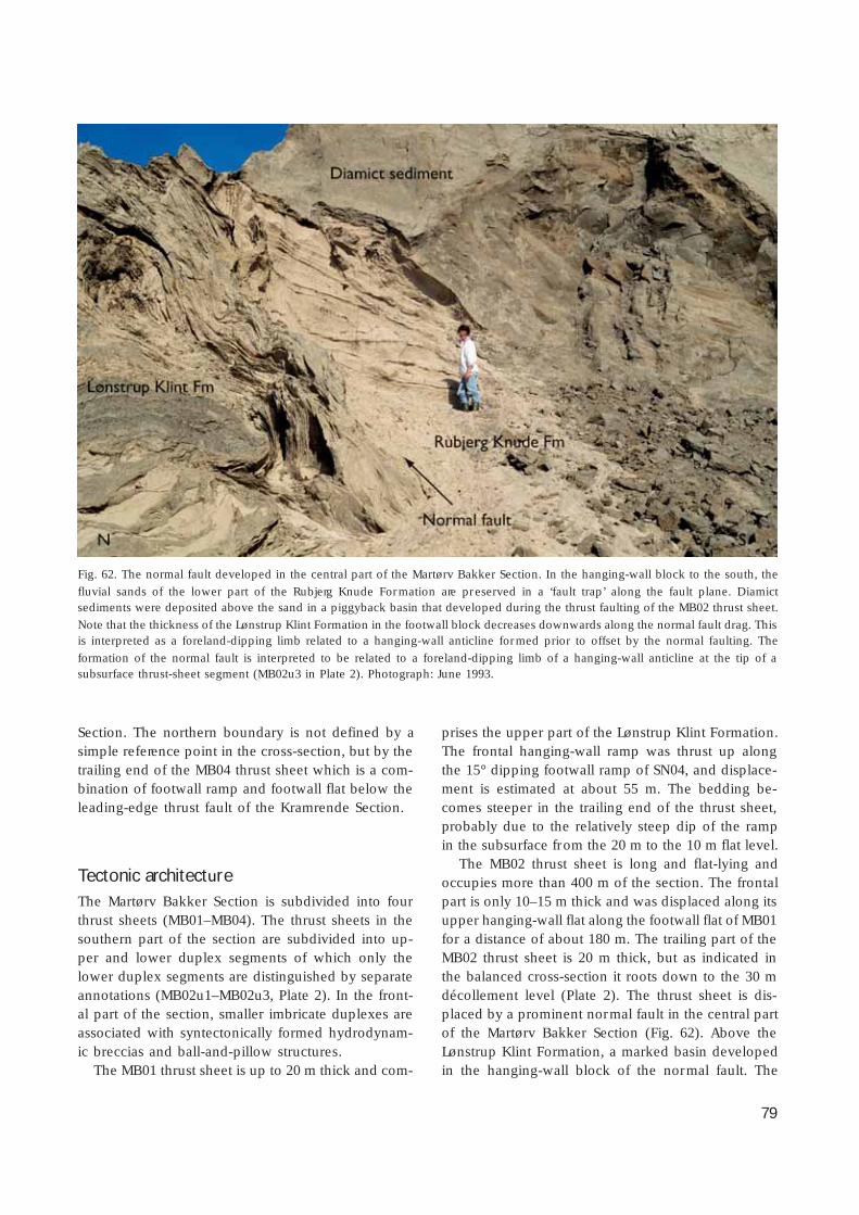
79
Section. The northern boundary is not defined by asimple reference point in the cross-section, but by thetrailing end of the MB04 thrust sheet which is a com-bination of footwall ramp and footwall flat below theleading-edge thrust fault of the Kramrende Section.
Tectonic architectureThe Martørv Bakker Section is subdivided into fourthrust sheets (MB01–MB04). The thrust sheets in thesouthern part of the section are subdivided into up-per and lower duplex segments of which only thelower duplex segments are distinguished by separateannotations (MB02u1–MB02u3, Plate 2). In the front-al part of the section, smaller imbricate duplexes areassociated with syntectonically formed hydrodynam-ic breccias and ball-and-pillow structures.
The MB01 thrust sheet is up to 20 m thick and com-
prises the upper part of the Lønstrup Klint Formation.The frontal hanging-wall ramp was thrust up alongthe 15° dipping footwall ramp of SN04, and displace-ment is estimated at about 55 m. The bedding be-comes steeper in the trailing end of the thrust sheet,probably due to the relatively steep dip of the rampin the subsurface from the 20 m to the 10 m flat level.
The MB02 thrust sheet is long and flat-lying andoccupies more than 400 m of the section. The frontalpart is only 10–15 m thick and was displaced along itsupper hanging-wall flat along the footwall flat of MB01for a distance of about 180 m. The trailing part of theMB02 thrust sheet is 20 m thick, but as indicated inthe balanced cross-section it roots down to the 30 mdécollement level (Plate 2). The thrust sheet is dis-placed by a prominent normal fault in the central partof the Martørv Bakker Section (Fig. 62). Above theLønstrup Klint Formation, a marked basin developedin the hanging-wall block of the normal fault. The
Fig. 62. The normal fault developed in the central part of the Martørv Bakker Section. In the hanging-wall block to the south, the
fluvial sands of the lower part of the Rubjerg Knude Formation are preserved in a ‘fault trap’ along the fault plane. Diamictsediments were deposited above the sand in a piggyback basin that developed during the thrust faulting of the MB02 thrust sheet.
Note that the thickness of the Lønstrup Klint Formation in the footwall block decreases downwards along the normal fault drag. Thisis interpreted as a foreland-dipping limb related to a hanging-wall anticline formed prior to offset by the normal faulting. The
formation of the normal fault is interpreted to be related to a foreland-dipping limb of a hanging-wall anticline at the tip of asubsurface thrust-sheet segment (MB02u3 in Plate 2). Photograph: June 1993.
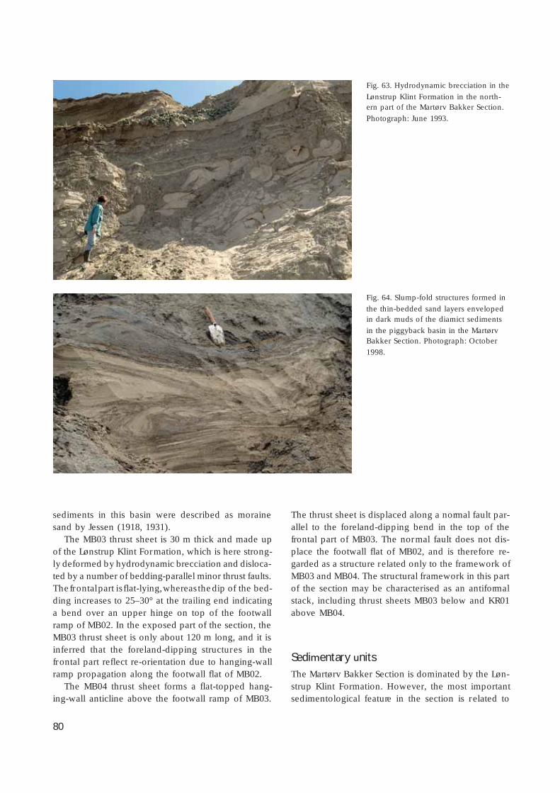
80
sediments in this basin were described as morainesand by Jessen (1918, 1931).
The MB03 thrust sheet is 30 m thick and made upof the Lønstrup Klint Formation, which is here strong-ly deformed by hydrodynamic brecciation and disloca-ted by a number of bedding-parallel minor thrust faults.The frontal part is flat-lying, whereas the dip of the bed-ding increases to 25–30° at the trailing end indicatinga bend over an upper hinge on top of the footwallramp of MB02. In the exposed part of the section, theMB03 thrust sheet is only about 120 m long, and it isinferred that the foreland-dipping structures in thefrontal part reflect re-orientation due to hanging-wallramp propagation along the footwall flat of MB02.
The MB04 thrust sheet forms a flat-topped hang-ing-wall anticline above the footwall ramp of MB03.
The thrust sheet is displaced along a normal fault par-allel to the foreland-dipping bend in the top of thefrontal part of MB03. The normal fault does not dis-place the footwall flat of MB02, and is therefore re-garded as a structure related only to the framework ofMB03 and MB04. The structural framework in this partof the section may be characterised as an antiformalstack, including thrust sheets MB03 below and KR01above MB04.
Sedimentary unitsThe Martørv Bakker Section is dominated by the Løn-strup Klint Formation. However, the most importantsedimentological feature in the section is related to
Fig. 63. Hydrodynamic brecciation in the
Lønstrup Klint Formation in the north-ern part of the Martørv Bakker Section.
Photograph: June 1993.
Fig. 64. Slump-fold structures formed in
the thin-bedded sand layers envelopedin dark muds of the diamict sediments
in the piggyback basin in the MartørvBakker Section. Photograph: October
1998.

81
the basin developed at the top of the hanging-wallblock connected to the normal fault displacing theMB02 thrust sheet (Fig. 62). The deposits in this basinare regarded as an exotic part of the Rubjerg Knude For-mation, and are described under this heading below.
The southern part of the Martørv Bakker Section isunconformably overlain by the Vendsyssel Formation,the initially glaciotectonic truncation being superim-posed by a post-glacial erosional unconformity. A Holo-cene erosional unconformity truncates the Vendsys-sel Formation as well as the glaciotectonic unconform-ity, and the peat deposited on this unconformity is upto 2 m thick in the northern part of the section, whereit is covered by modern aeolian dunes up to 20 m high.
Lønstrup Klint Formation
The lower part of the Lønstrup Klint Formation is mud-rich. It is exposed in the northern part of the section,where it was thrust above the hanging-wall flat fromthe décollement surface 25–28 m below sea level. Theupper part of the formation is dominated by 0.5–1.5m thick sand beds interlayered with thin beds of hor-izontally laminated mud, which typically has beenmobilised to form hydrodynamic breccias. In the south-ern part of the section, the beds are strongly affectedby ball-and-pillow deformation (Fig. 63).
Rubjerg Knude Formation
The Rubjerg Knude Formation comprises two units:(1) a lower 3 m thick sand unit only exposed alongthe prominent normal fault in the central part of theMartørv Bakker Section, and (2) a c. 15 m thick diamic-tite interpreted as a glaciolacustrine mud with rede-posited clasts. The first unit was deposited on theL/R-unconformity, and comprises light yellowish me-dium-grained sand (Fig. 26). The diamictite unit restspartly on the lower sand unit, and partly on the L/R-unconformity at the top of the Lønstrup Klint Forma-tion. The diamictite is dark grey, and comprises weaklylaminated mud interbedded with structureless, irre-gularly distributed matrix-supported beds containing
Fig. 65. A schematic diagram explaining the development of the hydrodynamic brecciation displayed in Fig. 63. The formation of thestructure was the result of three phases of deformation. In the first phase, a succession of sandy turbidites interbedded with mud (1)
was affected by loading to form the ball-and-pillow structures (2). In the second phase, the ball-and-pillow structures were dis-placed by thrust faulting (3). During the third phase, the mobilised mud intruded up thorough the thrust-fault surface (4), demon-
strating the syntectonic development of the hydrodynamic brecciation.

82
unsorted clasts in a matrix of sandy mud (Fig. 26). Inthe lowermost 2 m of the diamictite succession, thematrix-supported clasts were probably derived by re-deposition of coarse-grained material eroded from theL/R-unconformity to the north. About 3 m up in thesuccession, a c. 1 m thick bed occurs with clay clasts10 cm in size deposited in a weakly clay-laminatedand sand-streaked silty mud. This bed is overlain bythree 1.5–3 m thick units of isoclinally slump-folded,thin-bedded, fine-grained sand encased in dark struc-tureless mud (Fig. 26). These units are interpreted asslump-folded sheets derived from the Lønstrup KlintFormation (Fig. 64). The middle and upper slump-unitsare separated by a c. 5 m thick interval dominated bysandy mud with scattered clasts and a few thin sandbeds. The uppermost sand bed was not af fected byslumping and shows large-scale trough cross-bedding.
The lower part of the diamictite succession is strong-ly disturbed by hydrodynamic brecciation with meso-scopic-scale diapirs rising from the top of the Løn-strup Klint Formation and penetrating upwards intothe diamict sediments. This indicates that the diamic-tites were part of the main sedimentation affected byglaciotectonic disturbances.
StructuresIn the Martørv Bakker Section, three types of structuralelements were studied: (1) imbricate duplexes domi-nating the southern part of the section, (2) the normalfault in the central part of the section, and 3) hydro-dynamic brecciation contemporaneous with, or super-imposed on, ball-and-pillow structures (Figs 63, 65).
Imbricate duplexes
The imbricate duplexes in the southern part of thesection constitute rhomb-shaped segments 10 to 25 min size bounded by low-angle thrust faults. Minor im-bricates may occur along the thrust faults, but the thrustfaults are mainly narrow fracture surfaces without signi-ficant brecciation.
A mini-scale example of duplex formation is shownin Fig. 66. Although the structure is related to intrafor-mational deformation of the beds, it illustrates instruc-tively the formation of hanging-wall ramp propaga-tion of a stacked footwall ramp. Thus the footwall rampis formed by the trailing edges of two duplex seg-ments that were displaced one over the other to form
a single planar ramp for the propagation of the upperthrust sheet. Flame-like upright minor anticlines areinterpreted as compressed hanging-wall anticlinesformed during the sequential propagation of the vari-ous ramps. On top of the upper footwall hinge, a radialflame structure probably indicates the site of incipientdiapirism (Fig. 66). The formation of foreland-dippingthrust structures above the tip of a lower duplex seg-ment is also apparent.
Normal fault
The normal fault in the central part of the section isan uneven fault plane striking E–W with a dip of about45° to the south. Displacement along the fault planeis about 25 m, and a set of minor normal listric faultsdisplace the top of the hanging-wall block (Fig. 62).The footwall block comprises the Lønstrup Klint For-mation, which decreases in thickness southwards andforms an irregularly folded drag along the fault plane.At the top of the hanging-wall block, the diamict sed-iments described above are discordantly superposedon the light-coloured sand at the base of the RubjergKnude Formation.
Hydrodynamic brecciation
Ball-and-pillow structures occur in the sand-rich partsof the Lønstrup Klint Formation, where hydrodynam-ic mud mobilisation created chaotic breccias (Fig. 63).The initial size of the sand ball-and-pillow structuresis related to the primary thickness of the beds, butsubsequent to the sedimentary load deformation theywere distorted and deformed during thrust-fault relatedmud remobilisation. In Fig. 63, the distorted ball-and-pillow structures can be seen to be displaced by minorthrust faults, and these thrust faults were intruded bymobilised mud. The sequential development of thishydrodynamic brecciation is illustrated in Fig. 65,where three phases of deformation are recognised,although these probably developed progressivelyduring thrust-fault displacement and related loadingof superposed thrust sheets.
Interpretation of structural developmentThe thickness of MB01 implies that the décollementsurface in the southern part of the section is situated

83
at the 20 m level. The thickness of MB03 is 30 m,implying that the décollement level stepped down 10m somewhere in the central part of the section. Alower footwall ramp and a corresponding hanging-wall ramp must therefore be included in the balancedcross-section. The L/R-unconformity reference surfaceon top of the MB02 thrust sheet was about 20 m abovepresent sea level prior to the normal fault displace-ment, which indicates that a duplex 20 m in thicknessis situated below the trailing end of MB02. The lowerfootwall ramp responsible for the fault-propagationfolding of the antiformal stack in the northern part of
the section, estimated from the bend of the trailingends of MB02 and MB03, must be situated belowMB02. The structural model therefore suggests that asubsurface duplex was formed by segments of theMB02 thrust sheet situated between the 20 and 30 mlevels (MB02u1–MB02u3). The footwall ramp thusconstitutes two 10 m thick duplex segments stackedon top of each other.
Consequently, a hanging-wall anticline with a fore-land-dipping limb formed above the hanging-wallramp of MB02 and was translated along a footwallflat. The model further suggests that the hanging-wall
Fig. 66. A model of duplex formation is here illustrated by a mini-scale structure related to intraformational deformation of beds in
the Lønstrup Klint Formation, central part of Martørv Bakker Section. The duplex comprises two segments, which were derived fromthe bed underlying the lower footwall flat (lower FWF). The footwall ramp for the segments is situated to the left outside the frame
of the figure. The lower segment is a relatively short one, which was thrust over by the upper segment during the push from theramping of the upper thrust sheet. During propagation up the footwall ramp, the trailing edges of the two segments were displaced
to form one planar ramp for the upper thrust sheet, which was further translated over the duplex to a foreland-dipping bend createdabove the tip of the lower duplex segment. The flame-like upright anticlines are interpreted as compressed hanging-wall anticlines
formed during the sequential propagation of the various ramps. Note the radial flame structures at the upper footwall hingeindicating incipient diapirism. The small normal faults to the left of the trowel (15 cm in size) are thought to reflect similar foreland-
dipping features in the subsurface. FWH, footwall hinge; FWR, footwall ramp; uFWF, upper footwall flat; HWF, hanging-wall flat; R,ramp. Photograph: June 1993.

84
structure is a composite feature partly constructed bythe hanging-wall anticline related to the tip of theMB02u3 segment folded over the footwall ramp ofMB02u2, and partly by the hanging-wall anticline re-lated to the translation of the main hanging-wall rampof MB02 along the 10 m level. The foreland-dippinglimb of this structure corresponds well with a 45°south-dipping normal fault with a vertical displace-ment of about 20 m.
It is therefore concluded that the northern slope ofthe diamict sedimentary basin was formed by the nor-mal fault reflecting the foreland-dipping limb of ahanging-wall anticline. The southern more gently dip-ping slope of the basin was formed by the bend ofMB02 due to its propagation up along the footwallramp and flat of MB01. This footwall thrust fault is acomposite imbricate duplex, which hampers the ex-act distinction of ramp-flat relationships. The slump-folded units in the basin are interpreted as the resultof gravity slides derived from the crest of the hang-
ing-wall anticline or the tip of the MB04 thrust sheetpropagating from the north. The sediments filling thebasin represent redeposited material derived from thethrust-fault elevated part of the Lønstrup Klint Forma-tion, the coarse-grained clastics on the L/R-unconform-ity, and the lowermost part of the Rubjerg Knude For-mation. The basin is interpreted as a piggyback basinwith syntectonic deposition during the translation ofthe MB02 thrust sheet.
Kramrende SectionFrom the south, the first significant macroscopic-scalediapir occurs in the Kramrende Section (the Kram-rende diapir). Although mobilisation features alsooccur in sections farther to the south, this diapir isregarded as the most distal in the glaciotectonic thrust-fault complex. The thickness of the thrust sheet host-ing the Kramrende diapir suggests it is related to the
Fig. 67. The northern part of the KR01 thrust sheet where the lithostratigraphic reference section of the Lønstrup Klint Formation
(Fig. 21) is situated. The thrust sheet is fault-bend-folded up along an initially low-angle (c. 8°) footwall ramp, which was subse-quently folded into the present more steeply dipping orientation. Note the reverse faults interpreted as small back-thrust faults.
Photograph: June 1993.

85
deep level of thrust-fault rooting, which is about 30 mbelow the L/R-unconformity. The thrust sheet to thesouth of the Kramrende diapir and two thrust sheetsto the north are included in the section because theyare all affected by the structures related to the diapir.The frontal edge of the Kramrende Section is formedby the footwall ramp beneath the first thrust sheet(KR01, see Plates 1, 2). This thrust fault is identicalwith the trailing-edge footwall ramp of the MartørvBakker Section, which is responsible for the markedmonoclinal fault-bend folding of the KR01 thrust sheet(Fig. 67). The steps to the beach are situated in thegully between the KR01 thrust sheet and the Kram-rende diapir. The steps lead up to the summerhouse
area at Oddervej, and are referred to as the Kram-rende steps or the Oddervej Trappe.
Tectonic architectureThe Kramrende Section consists of four thrust sheets(KR01–KR04; Plates 1, 2). The frontal thrust sheet (KR01)is ramped over the MB04 footwall ramp in the Mar-tørv Bakker trailing thrust sheet. At the north end ofKR01, the L/R-unconformity is situated about c. 10 ma.s.l., which indicates that the KR01 hanging-wall ramppropagated along an intermediate footwall flat (FWF).The upper ramping along the MB04 footwall ramp is
Fig. 68. Ball-and-pillow structure
developed in the sandy turbidite bedbetween 4 and 5 m in Fig. 21. The
structure is interpreted as a loadstructure formed immediately after
sedimentation. Additional load struc-tures can be seen at the base of the
sand bed, where flame structures relatedto the underlying clayey bed intrude the
base of the sand bed. Above the ball-and-pillow structure, pinch and swell
structures within the sand bed are alsointerpreted as gravity load structures.
Photograph: June 1993.
Fig. 69. In the upper part of the KR04
thrust sheet in the Kramrende Section,the Rubjerg Knude Formation forms a
piggyback basin, which is overthrust bythe BR01 thrust sheet in the southern
part of the Brede Rende Section. Thethrust fault displayed in the photograph
is a hanging-wall flat for the thrust sheetBR01 (BR01HWF) and footwall ramp of
thrust sheet KR04 (KR04FWR). A minorsatellite thrust fault was formed below
the main thrust at a late stage of faultpropagation after the sand of the
Rubjerg Knude Formation had beensomewhat compacted. Photograph: June
1984.
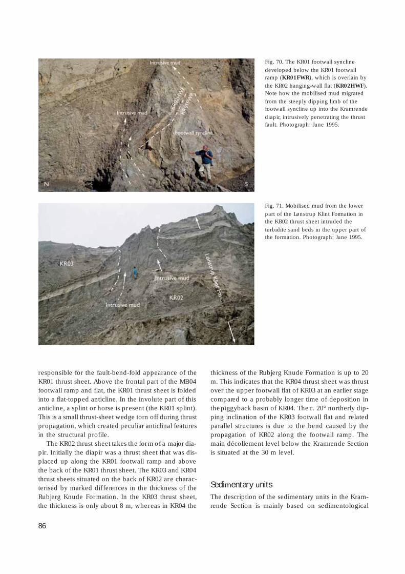
86
responsible for the fault-bend-fold appearance of theKR01 thrust sheet. Above the frontal part of the MB04footwall ramp and flat, the KR01 thrust sheet is foldedinto a flat-topped anticline. In the involute part of thisanticline, a splint or horse is present (the KR01 splint).This is a small thrust-sheet wedge torn off during thrustpropagation, which created peculiar anticlinal featuresin the structural profile.
The KR02 thrust sheet takes the form of a major dia-pir. Initially the diapir was a thrust sheet that was dis-placed up along the KR01 footwall ramp and abovethe back of the KR01 thrust sheet. The KR03 and KR04thrust sheets situated on the back of KR02 are charac-terised by marked dif ferences in the thickness of theRubjerg Knude Formation. In the KR03 thrust sheet,the thickness is only about 8 m, whereas in KR04 the
thickness of the Rubjerg Knude Formation is up to 20m. This indicates that the KR04 thrust sheet was thrustover the upper footwall flat of KR03 at an earlier stagecompared to a probably longer time of deposition inthe piggyback basin of KR04. The c. 20° northerly dip-ping inclination of the KR03 footwall flat and relatedparallel structures is due to the bend caused by thepropagation of KR02 along the footwall ramp. Themain décollement level below the Kramrende Sectionis situated at the 30 m level.
Sedimentary unitsThe description of the sedimentary units in the Kram-rende Section is mainly based on sedimentological
Fig. 70. The KR01 footwall syncline
developed below the KR01 footwallramp (KR01FWR), which is overlain by
the KR02 hanging-wall flat (KR02HWF).Note how the mobilised mud migrated
from the steeply dipping limb of thefootwall syncline up into the Kramrende
diapir, intrusively penetrating the thrustfault. Photograph: June 1995.
Fig. 71. Mobilised mud from the lower
part of the Lønstrup Klint Formation inthe KR02 thrust sheet intruded the
turbidite sand beds in the upper part ofthe formation. Photograph: June 1995.
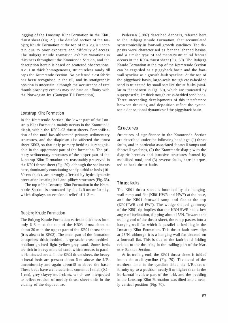
87
logging of the Lønstrup Klint Formation in the KR01thrust sheet (Fig. 21). The detailed section of the Ru-bjerg Knude Formation at the top of this log is uncer-tain due to poor exposure and dif ficulty of access.The Rubjerg Knude Formation exhibits variations inthickness throughout the Kramrende Section, and thedescription herein is based on scattered observations.A c. 1 m thick homogeneous, structureless sandy tillcaps the Kramrende Section. No preferred clast fabrichas been recognised in the till, and its stratigraphicposition is uncertain, although the occurrence of rarerhomb porphyry erratics may indicate an affinity withthe Norwegian Ice (Kattegat Till Formation).
Lønstrup Klint Formation
In the Kramrende Section, the lower part of the Løn-strup Klint Formation mainly occurs in the Kramrendediapir, within the KR02–03 thrust sheets. Remobilisa-tion of the mud has obliterated primary sedimentarystructures, and the diapirism also affected the thrustsheet KR03, so that only primary bedding is recognis-able in the uppermost part of the formation. The pri-mary sedimentary structures of the upper part of theLønstrup Klint Formation are reasonably preserved inthe KR01 thrust sheet (Fig. 20), although the sedimentshere, dominantly constituting sandy turbidite beds (10–50 cm thick), are strongly affected by hydrodynamicbrecciation creating ball-and-pillow structures (Fig. 68).
The top of the Lønstrup Klint Formation in the Kram-rende Section is truncated by the L/R-unconformity,which displays an erosional relief of 1–2 m.
Rubjerg Knude Formation
The Rubjerg Knude Formation varies in thickness fromonly 6–8 m at the top of the KR03 thrust sheet toabout 20 m in the upper part of the KR04 thrust sheet(it is absent in KR02). The main part of the formationcomprises thick-bedded, large-scale cross-bedded,medium-grained light yellow-grey sand. Some bedsare rich in heavy mineral sand, which occurs in paral-lel-laminated strata. In the KR04 thrust sheet, the heavymineral beds are present about 6 m above the L/R-unconformity and again about15 m above the base.These beds have a characteristic content of small (0.1–1 cm), grey clayey mud-clasts, which are interpretedto reflect erosion of muddy thrust sheet units in thevicinity of the depocentre.
Pedersen (1987) described deposits, referred hereto the Rubjerg Knude Formation, that accumulatedsyntectonically in footwall growth synclines. The de-posits were characterised as ‘banana’ shaped basins,and a similar type of sedimentary/structural featureoccurs in the KR04 thrust sheet (Fig. 69). The RubjergKnude Formation at the top of the Kramrende Sectioncan be regarded as a piggyback basin and the foot-wall syncline as a growth-fault syncline. At the top ofthe piggyback basin, large-scale trough cross-beddedsand is truncated by small satellite thrust faults (simi-lar to that shown in Fig. 69), which are truncated bysuperposed c. 1 m thick trough cross-bedded sand beds.Three succeeding developments of this interferencebetween thrusting and deposition reflect the syntec-tonic depositional dynamics of the piggyback basin.
StructuresStructures of significance in the Kramrende Sectionare described under the following headings: (1) thrustfaults, and in particular associated footwall ramps andfootwall synclines, (2) the Kramrende diapir, with thediapiric breccias and intrusive structures formed bymobilised mud, and (3) reverse faults, here interpre-ted as back-thrust faults.
Thrust faults
The KR01 thrust sheet is bounded by the hanging-wall ramp and flat (KR01HWR and HWF) at the base,and the KR01 footwall ramp and flat at the top(KR01FWR and FWF). The wedge-shaped geometryof the KR01 tip implies that the KR01HWR had a lowangle of inclination, dipping about 15°N. Towards thetrailing end of the thrust sheet, the ramp passes into ahanging-wall flat which is parallel to bedding in theLønstrup Klint Formation. This thrust fault now dipsat 25°N, although it is a hanging-wall flat situated ona footwall flat. This is due to the fault-bend foldingrelated to the thrusting in the trailing part of the Mar-tørv Bakker Section.
At its trailing end, the KR01 thrust sheet is foldedinto a footwall syncline (Fig. 70). The bend of thenorthern limb in the syncline lifted the L/R-uncon-formity up to a position nearly 5 m higher than in thehorizontal involute part of the fold, and the beddingin the Lønstrup Klint Formation was tilted into a near-ly vertical position (Fig. 70).

88
The KR02 thrust sheet was thrust up along a c. 25°dipping footwall ramp (KR01FWR) onto the upperfootwall flat above the Rubjerg Knude Formation ofthe KR01 thrust sheet. The KR02 thrust fault is appar-ently a hanging-wall flat which indicates a rather longdisplacement for thrusting. The top surface of KR02 isa footwall flat upon which the KR03 hanging-wall flatis situated, only bringing different stratigraphic levelsof the Lønstrup Klint Formation into contact. The dipof the thrust fault is parallel to the dip of the KR02–KR01 thrust fault. The footwall flat of the KR03 thrustsheet is overlain by a c. 80 m long hanging-wall flat ofKR04. The Lønstrup Klint Formation is only about 8–10 m thick above the hanging-wall flat (KR04HWF), in-dicating a fairly long intermediate flat (at the 10 mlevel below the reference surface). At the trailing endof KR04, the thickness increases indicating the pres-ence of a hanging-wall ramp at the base of the thrustsheet, and a footwall syncline similar to that describedin KR01 is present. In the upper part of the KR04 thrustsheet, the sediments deposited in the footwall growthsyncline became overturned along the northern limbduring translation of the hanging-wall ramp of BR01,as described above (Fig. 69).
Kramrende diapir
The Kramrende diapir constitutes the main part ofKR02. The diapirism also affected the trailing end ofKR01 (Fig. 70) as well as some parts of KR03. As shownin Fig. 71, mud of the lower part of the Lønstrup KlintFormation in KR02 became mobilised and intrudedthe overlying turbidite sand beds and also penetratedupwards into the overlying KR03 thrust sheet. Figure70 illustrates a thrust fault penetrated by intrusive mudat the footwall ramp of KR01. Here, the mobilised mudfrom the steeply inclined northern limb of the foot-wall syncline intruded into the mud-breccia along andabove the hanging-wall flat of KR02. A large part ofthe boundary between KR02 and KR03 was deformedin a similar way and the primary layering destroyed.
Reverse faults
In the Kramrende Section, significant steeply dippingreverse faults occur in the northern part of KR01 (Fig.67), and in the middle part of the KR03 thrust sheet.The displacement is only about 30–50 cm on the steepsouth dipping faults in KR01; the spacing betweenthe faults varies from 3–9 m, and often the faults canbe traced down into the tectonic breccia above the
Fig. 72. Reverse fault-splay fan developed on the back of KR03 and also displacing the overlying KR04 thrust sheet. The structureis interpreted as a back-thrust fault-splay formed during the KR03 propagation over the upper footwall ramp situated on the back of
KR02. Photograph: July 1994; figure at fault-splay centre for scale.

89
hanging-wall flat. In the KR03 thrust sheet, the reversefaults form a fault splay fan with individual faults dip-ping moderately to steeply to the south (Fig. 72); dis-placement varies from about 20 cm up to about 3 m.
The reverse faults appear to have formed duringthrust-sheet propagation over a ramp hinge and areinterpreted as back thrusts. A bend over a shallowdipping ramp will only result in minor displacementon steeply dipping back thrusts, whereas bending oversteeply dipping ramps creates low-angle back thrustswith potentially greater displacements.
Interpretation of structural developmentThe balanced cross-section indicates that the KR01thrust sheet was about 350 m long, of which a majorpart of the front tip has been eroded away. The amountof displacement is deduced from a series of balancedapproximations to be 160 m (see Plate 2). The foot-wall ramp of KR01 is interpreted to root in the 30 m
décollement level, which indicates that the lower hang-ing-wall ramp of KR01 was displaced onto the inter-mediate footwall flat above the trailing segment ofMB04. Thus the lift and steep tilt of the northern limbin the KR01 footwall syncline is interpreted to haveformed during the displacement of the lower hang-ing-wall ramp (KR01HWR) along the trailing-end foot-wall flat of MB04 (MB04FWF).
The tip of the KR02 thrust sheet has been erodedaway. To avoid exaggeration, the thrust fault is inter-preted to have continued only about 15 m up in theair further to the south, which implies that displace-ment of KR02 was in the order of 50 m. The main partof the KR02 thrust sheet present in the cross-sectionis above the hanging-wall flat brought up from the 30m décollement level. It is evident that the mobilisedmud was derived from this low level and that it wasactivated in diapirism during the thrust-sheet propa-gation over the footwall ramps (KR01FWR) and itshinge bend.
It is difficult to estimate the displacement for the
Fig. 73. The Brede Rende diapir in the frontal part of the Brede Rende Section. The frontal part of the BR02 thrust sheet was thrust
up on its hanging-wall ramp (BR02HWR) along the footwall ramp, which turned into the KR04 footwall flat (KR04FWF). At anearly stage of thrusting, probably while the hanging-wall ramp passed by a lower footwall hinge, diapirism developed. The mobil-
ised mud also intruded the L/R-unconformity and formed mushroom-shaped diapirs in the Rubjerg Knude Formation. Photograph:June 1984.

90
KR03 thrusting. Its relationship to the footwall flat ofKR02 indicates that it was thrust along a hanging-wallflat in the order of 60 m. However, before the KR03thrusting was complete, the KR04 thrust sheet wasalready emplaced on its back. The displacement ofKR04 can be determined in the cross-section to be 66m. The implications of KR04 being thrust onto KR03are that the sedimentation of the Rubjerg Knude For-mation on top of KR03 ceased, and with the contin-ued propagation of KR03 over the footwall ramp, theback-thrust splay also affected the KR04 thrust sheetthat was being passively transported piggyback onKR03.
Brede Rende SectionFor more than a century, groundwater drainage hasbeen concentrated at a spring at Brede Rende. Fromthe spring, situated at the base of the cliff, a streamhas over the years eroded a large funnel-shaped gullybehind the cliff facing the sea. Groundwater erosionsuccessively stepping backwards is thus responsiblefor the wide gully and for the locality name (Danish:brede = wide; rende = gully). The groundwater trans-missivity is, of course, governed by the geology of theBrede Rende Section, such that the spring wells outfrom the unconformity surface between the clayeyLønstrup Klint Formation and the permeable sand ofthe Rubjerg Knude Formation. The water initiallydrained in a southerly direction, but the present north-erly drainage system is exposing the structures of thenorthern flank of Brede Rende in an isolated cliff. It islikely that this cliff will be completely removed byerosion by the sea as well as by the stream within thenext few years leading to the formation of a broadgully at this location.
Important structural features currently exposed inthe Brede Rende Section comprise a polydiapiric com-plex, the Brede Rende diapir in the frontal part, theprominent Brede Rende normal fault (BRNF) in thecentral part, and a series of duplexes stacked in thetrailing end of the section.
Tectonic architectureThe Brede Rende Section comprises eight thrust sheets,annotated BR01–BR08 (Plate 2). The southern andfrontal boundary of the section is the footwall rampof KR04. The northern boundary is the thrust faultwhich partly acts as the BR08 footwall ramp and flat,and partly is the hanging-wall ramp for the SR01 thrustsheet in the Sandrende Section.
The BR01 thrust sheet is a relatively thin sheet thatwas displaced up along the KR04 footwall ramp, whichis c. 30 m thick and dips about 35°N. Above BR01, theBR02 thrust sheet was displaced more than 50 m alongits hanging-wall ramp onto the upper footwall flat ofKR04. The lower part of the thrust separating BR01and BR02 has been destroyed by penetrating diapir-ism, and together with BR03 these frontal thrust sheetsin the Brede Rende Section constitute the Brede Rendediapir (Figs 73, 74). The thrust sheets can still be re-garded as individual coherent elements, although their
Fig. 74. Detail of the internal structure of the Brede Rende dia-pir. Although the structure appears as a chaotic mixture of dis-
rupted sand beds ‘floating’ in a disorganised fashion in themobilised mud-matrix, some of the features could be interpre-
ted as relicts of hanging-wall anticlines (see dashed lines) formedin a developed stage during thrusting up along steep ramps.
Photograph: June 1985.

91
boundaries and internal structure have been stronglydistorted by diapirism.
BR03 is the longest thrust sheet in the Brede RendeSection, when the trailing lower segment is included(see Plates 1, 2). This is a constructional conventionbased on the consideration of which of the hanging-wall ramps should be traced down to the décollementsurface, and thus determine the annotation of the sub-surface duplex sheets (Plate 2, see later). The BR04thrust sheet is about 300 m long and is displaced bythe Brede Rende normal fault (BRNF) (Fig. 75). Northof the BRNF, the BR04 thrust sheet was thrust alongan intermediate BR03 footwall flat, and south of BRNFthe upper hanging-wall ramp and flat of BR04 werethrust over the upper footwall flat of BR03. The amountof displacement along thrust faults in this part of theBrede Rende Section is 50 m (measured in the cross-section of Plate 1) for BR03 as well as BR04. In BR04,the Rubjerg Knude Formation reaches its maximum
thickness of about 20 m in the Brede Rende Section,whereas the cover of Rubjerg Knude Formation on theback of BR02 and BR03 is less than 5 m thick.
The BR05 thrust sheet is relatively short and loca-ted between BR04 and BR06. The displacement alongits hanging-wall ramp is about 80–90 m and the initialramp-angle was c. 12°. The thickness of the RubjergKnude Formation on top of BR05 is only about 5 m,which indicates that the thrusting of the BR06 thrustsheet propagated early in the thrust development ofthe Brede Rende Section. The piggyback thrusting ofBR06 on BR05 on BR04 is one of the best examples ofa duplex structure in the Rubjerg Knude Glaciotecto-nic Complex.
The BR06 thrust sheet is a relative long and thinthrust sheet. To the north, the trailing end of BR06was thrust up over the footwall ramp of BR05. Fromthe footwall ramp hinge, an upper hanging-wall flat(BR06HWF) was displaced along the upper BR05 foot-
Fig. 75. The Brede Rende normal fault (BRNF). The frontal part of the BR06 thrust sheet has a normal displacement of about 20 mdown through the 45° dip normal fault, which can be measured from the hanging-wall flat of BR06 (BR06HWF ) north of the normal
fault to the BR06HWF south of the normal fault. In the footwall block of the BRNF, a series of minor normal faults make a stepwisedisplacement of the downthrown hanging-wall block. In the hanging-wall block of the BRNF, the bend of the thrust-fault structures
may be characterised as a roll-over anticline. Note that the BR06 hanging-wall flat transforms into a hanging-wall ramp (BR06HWR),which was thrust-displaced along the upper footwall flat of the BR04 thrust sheet (BR04FWF). Photograph: June 1984.

92
wall flat for about 200 m. As noted above, the BR06HWFdeveloped above the BR05 thrust sheet at an earlystage. The BR06 thrust sheet is divided into two seg-ments by the BRNF (Fig. 75). South of the BRNF, theupper hanging-wall ramp of BR06 was emplaced onthe BR04 upper footwall flat (Fig. 75).
The BR07 thrust sheet was thrust piggyback ontothe trailing-end segment of BR05 and propagated upalong the footwall ramp of BR06. It has very chaoticinternal structures dominated by polydiapirism. Theposition of the reference surface (L/R-unconformity)
at an elevation of 20–30 m above sea level indicatesthat the BR07 sheet was ramped up onto the flat abovea duplex composed of the trailing segments of BR03and BR05 (see later). There is only a thin cover of lessthan 5 m of the Rubjerg Knude Formation on the backof BR07, which is overlain by the BR08 hanging-wallramp.
The BR08 thrust sheet is the northernmost and up-permost sheet in the Brede Rende Section. It is thesmallest thrust sheet in the section, The thin frontaltip of the thrust sheet consists of the uppermost part
Fig. 76. Ball-and-pillow structures
superimposed by chaotic hydrodynamicbrecciation in the upper part of the
Lønstrup Klint Formation in the BredeRende Section. The brecciation was
formed by polysequential diapirismduring thrusting of the BR06 hanging-
wall flat (BR06HWF ) over the hinge tothe upper footwall flat of BR05
(BR05FWF) situated in the left side ofthe photograph. Photograph: June 1993.

93
of the Lønstrup Klint Formation, but with an up to 12 mthick succession of the Rubjerg Knude Formation ontop of the L/R-unconformity. Due to the bend up alongthe BR06 footwall ramp, the inclination of the BR07and BR08 thrust sheets is c. 25°N.
Sedimentary unitsThe Lønstrup Klint Formation is strongly affected byball-and-pillow load structures and hydrodynamicbrecciation. The maximum thickness of the formationexposed is only about 20 m (tentatively measured inBR02). The thickness of the Rubjerg Knude Formationvaries from thrust sheet to thrust sheet, indicating dif-ferential thrust-fault movement that either closed thepiggyback sedimentation and/or lifted the formation
up to a position exposed to erosion. The Rubjerg Knu-de Formation was also subjected to hydrodynamicbrecciation. At the top of the central part of the BredeRende Section, a glacitectonite and associated glacio-tectonic imbrications are interpreted to be related tothe advance of the Norwegian Ice; the sandy till isinterpreted to be the Kattegat Till Formation.
Lønstrup Klint Formation
The lower and intermediate parts of the Lønstrup KlintFormation are characterised by dark clayey mud. Theinterval 5 to 10 m below the L/R-unconformity is dom-inated by a few thick beds of light coloured sandyturbidites, and the uppermost 5 m is formed by thin-bedded sand beds interbedded with mud. The size of
Fig. 77. Small-scale ball-and-pillow structures distorted and in-
truded by water-escape injection. Note that dish structures wereformed above the water-escape pipe. Detail of chaotic breccia-
tion in the upper part of the Lønstrup Klint Formation; frontalpart of the BR06 thrust sheet in the Brede Rende Section. Pho-
tograph: June 1998.
Fig. 78. Small-scale disharmonic undulations formed by polyse-
quential diapirism in the thinly interbedded clays, silts and fine-grained sands of the upper part of the Lønstrup Klint Forma-
tion. Note the fold accentuation of the climbing ripple lamina-tion in the central part of the figure. Frontal part of the BR06
thrust sheet in the Brede Rende Section. Photograph: June 1998.

94
ball-and-pillow structures is typically related to theinitial thickness of the sand beds, and the subsequenthydrodynamic brecciation and chaotic structuresformed during water-escape activities (Figs 68, 76–78).
The L/R-unconformity at the top of BR04 truncatesa large ball-and-pillow structure at the top of the Løn-strup Formation just north of the normal fault (Fig.79). This implies that some of the load structures, andpossibly also initial water-escape dynamics, had com-menced prior to the development of the unconformity.It may be that this phase of ball-and-pillow formationwas initiated by the drainage of the large lake basin(see Sadolin et al. 1997). Thus the initiation of ball-and-pillow formation can be viewed as the conse-quence of vibration created by an increased watertransport over the beds. At this locality, the formationof ball-and-pillow structures was clearly not the effectof loading by over-thrusting, but only the result ofdensity variation of the primary sedimentary layers,since the top of the Lønstrup Klint Formation wasundergoing erosion and the gravel bed on the L/R-unconformity was deposited subsequently.
Rubjerg Knude Formation
The Rubjerg Knude Formation reaches a thickness of15 m in the upper part of the BR04 thrust sheet, but inthe rest of the Brede Rende Section it is less than 10 m
thick. The relatively thin nature of the formation (3–5m) in BR02, BR03, BR05 and BR07 is interpreted toindicate that these basins were over-thrust or thrust-elevated at an early stage of thrust propagation. Incontrast, deposition persisted in the piggyback basinsof BR04 and BR06 before their upper footwall flats wereoverthrusted and deposition ceased in the basins.
StructuresThree types of structural features are described fromthe Brede Rende Section: (1) diapir structures, includ-ing mesoscopic-scale sequential polydiapirs and hy-drodynamic brecciation, (2) the Brede Rende normalfault (BRNF), and (3) frost wedges.
Fig. 79. A large ball-and-pillow structure in the upper part of the Lønstrup Klint Formation, truncated by the L/R-unconformity. Thisrelationship demonstrates that at least part of the loading occurred prior to the thrust-fault emplacement. Photograph: June 1998.
Facing page – upper:Fig. 80. Normal fault network in the footwall block of the
Brede Rende normal fault developed in the BR04 thrustsheet. Photograph: June 1998.
Facing page – lower:
Fig. 81. Frost wedges recognised in the Rubjerg KnudeFormation. The one on the right side of the spade (A) has
well-developed, ‘upwards-fanning’ small-scale normal faults,whereas the one to the left of the spade (B) is a 5–10 cm
wide fracture with a sand-fill. Photograph: June 1997.

95
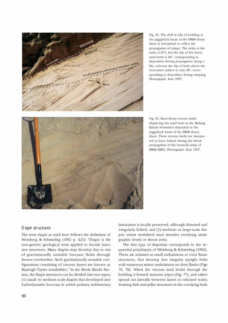
96
Diapir structures
The term diapir as used here follows the definition ofWeinberg & Schmeling (1992 p. 425): “Diapir is thenon-genetic geological term applied to ductile intru-sive structures. Many diapirs may develop due to riseof gravitationally unstable buoyant fluids throughdenser overburden. Such gravitationally unstable con-figurations consisting of viscous layers are known asRayleigh-Taylor instabilities.” In the Brede Rende Sec-tion, the diapir structures can be divided into two types:(1) small- to medium-scale diapirs that developed intohydrodynamic breccias in which primary sedimentary
lamination is locally preserved, although distorted andirregularly folded, and (2) medium- to large-scale dia-pirs where mobilised mud intrudes overlying strati-graphic levels or thrust units.
The first type of diapirism corresponds to the se-quential polydiapirs of Weinberg & Schmeling (1992).These are initiated as small undulations or even flamestructures, that develop into irregular upright foldswith numerous minor undulations on their flanks (Figs76, 78). When the viscous mud broke through thebedding it formed intrusive pipes (Fig. 77), and eitherspread out laterally between layers or released water,forming dish-and-pillar structures in the overlying beds
Fig. 82. The shift in tilts of bedding in
the piggyback basin of the BR08 thrustsheet is interpreted to reflect the
propagation of ramps. The strike is thesame (110°), but the dip of the lower
sand beds is 40°, corresponding todeposition during propagation along a
flat, whereas the dip of beds above thetruncation surface is only 28°, corre-
sponding to deposition during ramping.Photograph: June 1997.
Fig. 83. Back-thrust reverse faults
displacing the sand beds in the RubjergKnude Formation deposited in the
piggyback basin of the BR08 thrustsheet. These reverse faults are interpre-
ted to have formed during the thrustpropagation of the footwall ramp of
BR06/BR05. Photograph: June 1997.

97
(Fig. 77). In the Brede Rende Section, this type of dia-pirism occurs commonly in the upper sand-rich partof the Lønstrup Klint Formation and in the RubjergKnude Formation. A good example occurs at the tipof the BR05 thrust sheet, where the thrust fault(BR04FWF/BR05HWR) is completely obscured by hy-drodynamic brecciation.
Examples of the second type of diapirism includethe Brede Rende diapir and the Kramrende diapir. Herethe clay-rich units of the lower part of the LønstrupKlint Formation became mobilised by over-pressuredwater (or gas) to form an intrusive grey, homogene-ous mud. The diapirism in the Brede Rende Sectionwas formed syntectonically during ramping (Pedersen1987). The thrusting displaced some of the feeders inthe mushroom-shaped diapirs, and some of the dia-pirs intruded through the thrust sheets up into thethrust sheet above. Moreover, the mushroom-shapeddiapirs penetrate the L/R-unconformity at the top ofthe diapir (Fig. 73). It may also be noted that some ofthe diapir feeders have been tilted by the bendingproduced by ramp propagation (Fig. 4; Pedersen 1987).
Brede Rende normal fault
The Brede Rende normal fault (BRHF), in the centralpart of the Brede Rende Section, is a planar fault thatstrikes 100° and dips 45°S (Fig. 75). The vertical dis-placement is c. 20 m when measured from the hang-ing-wall (thrust-fault) flat of the BR06 in the footwallblock of the normal fault to the same flat in the hang-ing-wall block of the BRNF. A network of smaller nor-mal faults with minor displacements occurs in the foot-wall block (Fig. 80) and adds to the monoclinal bendin the footwall block of the BRNF. In the hanging-wall block, the BR06 thrust sheet is dragged along thefault plane and the drag is bounded by a minor splayfault. Moreover, a weakly developed rollover-anticlineoutlined by the BR06 thrust sheet occurs in the hang-ing-wall block of the BRNF (Fig. 75). Above the north-ern limb-bend of the rollover-anticline, a minor de-pression (c. 5 m deep) was formed. In this depres-sion, a series of minor imbricate sandy mud slumpsformed, which may be viewed as syn- to epitectonicdeposits at the top of the Rubjerg Knude Formationin BR06 related to faulting of the BRNF.
Frost wedges
Frost wedges or fossil ice wedges are recognised inthe Rubjerg Knude Formation, as preserved in theupper part of the BR04 thrust sheet. The clif f sectionhere became exposed after the cross-section (Plate 1)was drafted and is thus not included. It would havebeen situated near point 3975 m in the cross-section.The frost-wedge fractures are 5–10 cm wide and arefilled with structureless sand. Along the sides of thefractures, the bedding in the sand is bent down to-wards the fracture due to minor displacements alongsmall fanning normal faults; the vertical range of thefrost wedges is about 1–3 m (Fig. 81).
The presence of frost wedges in the Rubjerg Knu-de Formation clearly indicates that the sand wasground frozen, and thus also elevated above waterlevel in the glaciofluvial and glaciolacustrine environ-ment that prevailed during the deposition of the for-mation. The ground-frozen condition of the sand maybe the reason for the excellent preservation of thenormal fault network related to the BRNF.
Interpretation of structural developmentThe first thrust sheets to move were probably BR03and BR06, which ramped up to the upper footwall flatand moved southwards over a thin cover of the Ru-bjerg Knude Formation. In the balanced cross-section,the presence of the long, thin BR03 thrust sheet, andespecially BR06, requires that there has to be under-lying lower and intermediate duplex sheets. The bal-anced cross-section model favours a continuation inthe subsurface of several segments of the lower thrustduplex. The BR03 thrust sheet is viewed as a coher-ent thrust sheet, which from the ramp of the minorBR02 thrust sheet, continues along the lower décolle-ment surface at the 30 m level. The lower trailing-endduplex segment extends northwards to the thrust faultseparating the Brede Rende and the Sandrende Sec-tions (SR01HWR/BR08FWR). This trailing segment ofthe BR03 thrust sheet is estimated to be about 300 mlong, and the remaining five thrust sheets in the BredeRende Section have all been ramped up onto this seg-ment along which the allochthonous transport andpiggyback displacement took place.
The simplest model for understanding the frame-work of the duplexes is to accept segmentation of thetrailing end of the BR05 thrust sheet. It is necessarythat BR06 was thrust over BR05 before the trailing

98
end of BR05 was thrust up over the footwall ramp ofBR04. The existence of the intermediate BR04 hang-ing-wall ramp indicates that BR04 had to ramp up twofootwall ramps in dif ferent positions of the trailingend of BR03. Thus the model indicates that a lowerhanging-wall ramp of BR04 was emplaced along theintermediate footwall flat of BR03. According to theconstruction of the balanced cross-section, this alsonecessitates a lower duplex segment to be thrust upin front of the lower hanging-wall ramp and flat ofBR04. These dif ferential thrust displacements providean explanation for the development of the BRNF. Thedisplacement along the BRNF is consequently consid-ered to be due to two factors. The first 10 m offsetwas caused by normal faulting in front of BR05, wherea foreland-dipping bend of the BR06 hanging-wall flatwas created over the nose of the BR05 thrust sheet.The next 10 m displacement was caused by a fore-land-dipping limb of the tip of a duplex segment situ-ated beneath the BR04 thrust sheet causing the BR04hanging-wall flat to act as a normal fault.
At the
north end of the section, the BR07 thrust sheet,
which only has 3–4 m of the Rubjerg Knude Forma-tion at the top, was overthrust by the BR08 thrust sheetat an early stage. The thickness of about 10 m of Ru-bjerg Knude Formation on top of BR08 indicates thatafter the two thrust sheets were thrust-separated, depo-sition of Rubjerg Knude Formation continued in thepiggyback basin of BR08. This sedimentation proba-bly took place while BR08 in a piggyback position onBR07 ramped over a lower footwall ramp of BR03 andpropagated along an intermediate flat, passing overthe footwall ramp of BR05/BR06, before the tempo-rary
cessation of thrusting. In the BR08 piggyback ba-
sin, the propagation of ramps is reflected in the changein tilt of the bedding (Fig. 82). Moreover, a number ofminor back-thrusts have been recognised in these beds(Fig. 83), and are considered to have been related tothe ramp propagation.
In the dynamic development of the Brede RendeSection, both the frontal southern and the northernparts were involved in diapirism. In both parts, it is
Fig. 84. The Sandrende diapir developed in the SR02 thrust sheet. The arrow indicates the direction of reverse faulting, which marks
the prominent back thrust. Along the steep northern flank, the hanging-wall ramp of SR03 (SR03HWR ) was bent. The bend of theL/R-unconformity formed due to the fold-bend-folding of SR02 at the lower footwall ramp hinge.
99
evident that the diapirism was active after the em-placement of the thrust sheets, since the hanging-wallflats are penetrated by diapirs rising from a mobilisedunderlying thrust sheet. However, it is also evidentthat the diapirism ceased before the maximum com-pression of thrust sheets had occurred. The termina-tion of thrust compression was reached when themaximum inclination of the flats occurred. This coin-cided with the conclusive accumulated ramping ofpiggyback thrust sheets. Thus, the inclined positionof the feeders to the mushroom-shaped diapirs indi-cates a synthrust intrusive emplacement. It is there-fore concluded that the diapirism was activated byramp propagation and that some of the diapirs can beregarded as extreme developments of hanging-wallanticlines created during soft sedimentary deforma-tion (Fig. 74).
Sandrende SectionThe Sandrende Section is one of the most studied partsof the Lønstrup Klint cliff section (Fig. 5; Houmark-Nielsen et al. 1996; Sadolin et al. 1997). Even so, thedevelopment of this section is not fully understood,and some new and revised details are added here.The main feature of the section is a broad basin con-taining a thick succession of the Rubjerg Knude For-mation deposited in a piggyback basin. To the south,a diapir distorts this basin, and to the north the basinis over-thrust by a thrust sheet of the Stenstue RendeSection. The central part of the section preserves aremarkable development of normal faults. These wereformerly regarded to have formed in response to thevolume adjustments in the Sandrende diapir (Sadolinet al. 1997), but are now interpreted as elements of athrust-fault propagation model with differential du-plex segments ramping in the subsurface.
Tectonic architectureThe Sandrende Section comprises four thrust sheets(SR01–SR04). The southern boundary of the section isthe trailing-edge ramp of BR07 and BR08 in the BredeRende Section, and the northern boundary is the rathersteep (> 60°) trailing-edge ramp of SR04. The bound-ary with the Stenstue Rende Section to the north is acombination of this trailing-edge ramp and the hang-ing-wall flat of the frontal southernmost thrust sheet inthe Stenstue Rende Section (see below).
The transition between the Brede Rende Sectionand the Sandrende Section in the subsurface is notclear due to uncertain relationships between BR07–BR08 and SR01. The description below is based onthe preferred interpretation, which traces the trailing-edge ramp of BR08 in the Brede Rende Section downto the décollement surface 30 m below the referencesurface. This implies that the lowermost trailing endsof BR07 and BR03 remain as low-lying segments thatSR01 had to ramp over. An extra segment and somesmaller adjustment splints of the SR01 thrust sheet werealso left in the subsurface. This is reflected in some ofthe structural features exposed in the section betweenSR01 and SR02.
At the tip of the SR01 thrust sheet, the LønstrupKlint Formation forms a thin wedge, which indicatesthat the initial hanging-wall ramp (SR01HWR) onlyhad a dip of about 10°. However, after ramping wasconcluded, the thrust fault was steepened to thepresent dip of 40°N; the measured orientation of theramp is 108°/40°N. The displacement of SR01HWRalong the upper footwall ramp and flat of BR08 is c.53 m. The frontal part of SR01 has a bend, and it onlydips about 25°N due to the change in thrust-fault in-clination passing the upper footwall ramp hinge andthe subsequent introduction of a small satellite thrustfault displacing the lower part of SR01 up over the tip-wedge. The consequence of thrusting the thin c. 50 mlong frontal part of the thrust sheet is that in the bal-anced cross-section, a lower duplex segment (SR01u)must be accounted for, and that SR01u at an advancedstage of SR01 thrust propagation was picked up in thethrust translation (see below).
The SR02 thrust sheet was formerly interpreted as alarge-scale diapir (Sadolin et al. 1997; Fig. 84). In thepresent structural analysis, SR02 is treated as one largethrust sheet in which the mobilised mud underwentmud diapirism at a relatively late stage. This assump-tion permits an approximation of balancing the thrustsheets, accepting that the thrust faulting is evidentlythe most important part of the dynamic development.The argument for this is based on the fact that SR02over-thrust the back of SR01 with a displacement ofabout 100 m. This 100 m of displacement has to becompensated for by the same amount of displacementalong the lower décollement surface, which can becalculated to have taken place at a stratigraphic depthof 30 m below the L/R-unconformity. The thrusting ofSR02 resulted in a considerable amount of elevationduring propagation along footwall ramps (SR01FWRand BR03FWR), since the L/R reference surface is sit-

100
uated about 35–40 m above sea level in the cliff sec-tion. Thus the ramping and displacement along theupper flat took place before the final emplacement ofthe lower duplex segment of SR01, indicated by thenormal fault displacement of both SR01 and the front-al part of SR02.
As noted in the Kramrende Section description,steep ramping creates back-thrusting at the hinge ofthe hinterland-dipping limb. Thus the peculiar mush-room-shaped structure with a wing pointing to thenorth is considered to be the effect of reverse faultingdue to back-thrusting (Fig. 84). The reverse fault fea-ture may have been accentuated by re-orientated in-ternal detachment folding and irregular diapirism inthe Sandrende diapir. Furthermore, it should be notedthat the L/R-unconformity surface has a steep dip onthe northern flank of the Sandrende diapir. Near thebeach level, the L/R-unconformity bends into a gen-tle dip indicating that in the trailing end of SR02, thelower hanging-wall flat rests on the lower footwallflat coinciding with the décollement level at 30 m.
The SR03 thrust sheet is relatively small with a dis-placement of about 75 m. The tip of the thrust sheet isbent upwards into a nearly vertical position due todrag along the almost vertical northern flank of theSandrende diapir (SR02). Thus the SR03 thrusting wasrather early, but as the Rubjerg Knude Formation isabout 10 m thick in SR02 there was a significant timespan before SR03 was thrust up on the back of SR02.
SR03 was displaced up along the upper footwallramp, which is exposed in the cliff section. SR03 wasalso displaced along an intermediate flat situated atthe 20 m level, indicated by the thickness of the thrustwedge. During thrust propagation, the trailing end ofSR03 was cut off and left as an isolated duplex seg-ment, while the frontal part of SR03 was displacedalong the intermediate flat (see Plate 2).
SR03 was over-thrust by SR04 with a relatively shorttime gap, as indicated by the thin (3 m) succession ofRubjerg Knude Formation on top of SR03. The thrustdisplacement of SR04 over SR03 is about 60 m, and
Fig. 85. Conjugate normal faults developed in the Lønstrup Klint Formation in the SR04 thrust sheet. An offset of about 1 m can berecognised by correlating turbidite sand beds in the footwall block to the same beds in the hanging-wall block. The normal fault
framework is interpreted to be due to lateral extension in the SR04 thrust sheet during its propagation over the upper footwall hingeof an underlying duplex. Photograph: May 1995; measuring staf f divisions (centre) are 20 cm.
101
the accumulated displacement of the trailing end ofSR04 relative to SR02 is in the order of 135 m.
The frontal part of SR04 consists of a relatively thinwedge of the upper part of the Lønstrup Klint Forma-tion overlain by an up to 28 m thick succession of theRubjerg Knude Formation. In the central and rear partsof SR04, the thickness of the Lønstrup Klint Forma-tion increases to more than 20 m, indicating the exist-ence of a hanging-wall ramp which can be traced downto the décollement zone, 30 m below the L/R refer-ence surface. The central part of SR04 forms a broadhanging-wall anticline, where a number of extension-al normal faults cross-cut the Lønstrup Klint Forma-tion (Fig. 85). The southernmost normal fault in thissystem is considered to reflect the foreland-dippingfeatures formed due to displacement of the hanging-wall anticline along the intermediate flat. Finally, itshould be noted that the piggyback basin (RubjergKnude Formation) of SR04 is divided into two sub-basins, one in the southern frontal part and one inthe northern trailing part of the thrust sheet. The areabetween the sub-basins lacks the Rubjerg Knude For-mation because it corresponds to the crest of the hang-ing-wall anticline.
Sedimentary unitsThe type sections of the Lønstrup Klint and RubjergKnude Formations, as defined in this bulletin and pre-viously described by Sadolin et al. (1997), are situat-ed at Sandrende. As defined above, this succession isdivided here into the Lønstrup Klint Formation andthe overlying Rubjerg Knude Formation, which areseparated by the L/R-unconformity (Fig. 19). The Ru-bjerg Knude Formation is covered by an up to 1 mthick homogeneous sandy till, which is referred to theKattegat Till Formation (Fig. 30).
Lønstrup Klint Formation
In the Sandrende Section, the lower exposed part ofthe Lønstrup Klint Formation is composed of lamina-ted clayey to sandy mud, intercalated with a few thinsandy turbidites that grade up into finely laminatedclay-rich mud. In the upper part of the formation, thick-er turbidite sand beds with climbing ripples give theformation a banded light/dark coloured appearance(Figs 19, 85). Only very few load structures and hydro-dynamic breccias have been noted in the Sandrende
Section, except in the lower part of the SR04 sheetwhere ball-and-pillow structures and small-scale poly-diapirism have been observed (Fig. 86). The ball-and-pillow features are about 20 cm in thickness, which isprobably the thickness of the original beds; they aretypically elongated about 50–75 cm parallel to the strikeof the bedding, suggesting they were formed duringthe thrust deformation.
Rubjerg Knude Formation
The Rubjerg Knude Formation comprises three units:(1) a lower unit c. 5 m thick consisting of trough cross-bedded sand and gravel, (2) a middle unit dominatedby climbing ripple cross-laminated sand, and (3) anupper unit comprising alternating beds of small-scaleripple cross-laminated sand and trough cross-beddedsand (Fig. 19). The units reflect the change from fluvialto lacustrine and back to fluvial depositional environ-ments (Sadolin et al. 1997). The Rubjerg Knude For-mation has an onlapping relationship in the frontalpart of the SR04 thrust sheet, which reflects initial thrustfaulting during sedimentation (Sadolin et al.1997). Inthe central part of the SR04 thrust sheet, growth-faultsedimentation along normal faults is recorded in thelower part of the Rubjerg Knude Formation. Thegrowth faults coincide with the foreland-dipping limbof the hanging-wall anticline of SR04 (Fig. 87). Thissyntectonic sedimentation supports the piggybackbasin concept for deposition of the Rubjerg KnudeFormation. Moreover, a slumped block 0.5 × 2 m insize occurs along one of the normal faults indicatingthat the tip of the satellite thrust in SR04 was exposedto erosion and slumped into the basin. Similar slumpedblocks were observed on the northern flank of theSandrende diapir indicating that the diapir rose abovethe depositional surface during emplacement and thatfragments of the Lønstrup Klint Formation slumpedinto the piggyback basin. The synsedimentary rise ofthe vertical diapir wall was also reflected in sedimen-tation of small point-bar wedges along the verticalflank of the Sandrende diapir.
Towards the top of the Rubjerg Knude Formation,broad trough cross-bedding is observed. Minor thrustfaults splaying out from the tip of SS01 displace thecross-bedded sand, and the base of some of thetroughs dramatically truncate the thrust faults, in asimilar fashion to that observed in the BR04 piggy-back basin of Brede Rende (see above). At the top ofthe Rubjerg Knude Formation, sand was deposited in a

102
Fig. 86. Mobilisation and small-scale polydiapiric features developed in the upper part of the Lønstrup Klint Formation in theSandrende Section (trailing end of SR04). The polydiapirs started along a bed of clayey mud as small flames (with small wave-
length), which were subsequently folded around the taller diapirs. The sandy beds above and below constitute planar laminatedand climbing ripple cross-laminated fine-grained sand with organic debris and mud draping the ripples. Locally in this sand,
hydrodynamic mobilisation has created zones of mud-free structureless sand and the accumulation of mud forming dendriticstructures. The dynamic development of the structure is illustrated in Fig. 88.
Fig. 87. Extensional normal faults withrelated growth-fault sedimentation of
sand and gravel in the lower part of theRubjerg Knude Formation. The growth
faults are marked with arrows indicatingthe direction of displacement. The top
of the Rubjerg Knude Formation in theSR04 thrust sheet is over thrusted by the
SS01 thrust sheet. The two sheets areseparated by a thrust fault that acts as
footwall flat of SR04 (SR04FWF) andhanging-wall ramp of SS01 (SS01HWR).
Photograph: May 1995.
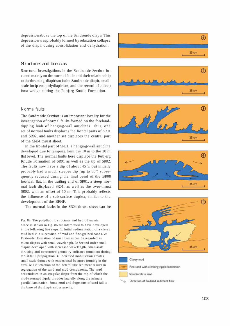
103
depression above the top of the Sandrende diapir. Thisdepression was probably formed by relaxation collapseof the diapir during consolidation and dehydration.
Structures and brecciasStructural investigations in the Sandrende Section fo-cused mainly on the normal faults and their relationshipto the thrusting, diapirism in the Sandrende diapir, small-scale incipient polydiapirism, and the record of a deepfrost wedge cutting the Rubjerg Knude Formation.
Normal faults
The Sandrende Section is an important locality for theinvestigation of normal faults formed on the foreland-dipping limb of hanging-wall anticlines. Thus, oneset of normal faults displaces the frontal parts of SR01and SR02, and another set displaces the central partof the SR04 thrust sheet.
In the frontal part of SR01, a hanging-wall anticlinedeveloped due to ramping from the 10 m to the 20 mflat level. The normal faults here displace the RubjergKnude Formation of SR01 as well as the tip of SR02.The faults now have a dip of about 45°S, but initiallyprobably had a much steeper dip (up to 80°) subse-quently reduced during the final bend of the BR08footwall flat. In the trailing end of SR01, a steep nor-mal fault displaced SR01, as well as the over-thrustSR02, with an offset of 10 m. This probably reflectsthe influence of a sub-surface duplex, similar to thedevelopment of the BRNF.
The normal faults in the SR04 thrust sheet can be
Fig. 88. The polydiapiric structures and hydrodynamic
breccias shown in Fig. 86 are interpreted to have developedin the following five steps. 1: Initial sedimentation of a clayey
mud bed in a succession of mud and fine-grained sands. 2:First-order formation of small flames can be regarded as
micro-diapirs with small wavelength. 3: Second-order smalldiapirs developed with increased wavelength. Small-scale
thrusting and overturned geometry indicates formation duringthrust-fault propagation. 4: Increased mobilisation creates
small-scale domes with extensional fractures forming in thecrest. 5: Liquefaction of the heterolithic sediment results in
segregation of the sand and mud components. The mudaccumulates in an irregular diapir from the top of which the
mud-saturated liquid intrudes laterally along the primaryparallel lamination. Some mud and fragments of sand fall to
the base of the diapir under gravity.

104
viewed as two sets of a fault framework. The first setformed 45–60°S dipping faults with displacements of1–3 m. The southerly dipping tilt of the L/R-uncon-formity is regarded as the foreland-dipping limb ofthe hanging-wall anticline formed in SR04 (Fig. 87).The faults above the foreland-dipping surface devel-oped as growth faults associated with syntectonic sed-imentation, as recorded in the lower part of the Ru-bjerg Knude Formation. During displacement alongthe normal faults, a minor satellite thrust cross-cut theSR04 thrust sheet, and the tip of the satellite thrustsheet was slump-faulted to form slumped blocks inthe growth-fault setting of the piggyback basin.
The normal fault network at the crest of SR04 isvery impressive (Fig. 85). The strike of the normalfaults is 090° with a dominant dip of 50°S, although asmall number of conjugate faults with a dip of 60–75°N also occur. In view of the angle of conjugatefaulting, these normal faults could have formed dueto the loading of the SS01 thrust sheet emplaced abovethe upper footwall flat of SR04, but could also haveformed due to necessary extensional adjustments dur-ing propagation over the hinge of the footwall ramp.
Diapir structures
The Sandrende diapir only af fected one thrust sheet(SR02), in contrast to the Brede Rende and Kramrendediapirs where two or more thrust sheets were involvedin the diapir formation. The most impressive featureof the Sandrende diapir is the major back-thrust, whichhas an offset of about 20 m towards the north. Initial-ly it was probably an almost vertical reverse fault,which was re-orientated and accentuated during thrust-fault propagation. A number of smaller reverse faultsoccur along the steep northern wall of the diapir, whichinternally is composed of mobilised mud. In the up-per part of the diapir, distorted bedding-structures iso-lated as ‘xenoliths’ in the upper part of the diapir areinterpreted as fragments of hanging-wall anticlines.Judging from the thickness of the diapir feeder, thediapir formed over a hanging-wall ramp where theSR02 thrusting ramped from the upper 10 m flat to thelower 20–30 m flat level.
The formation of diapirs was evidently initiated bymobilisation on a small scale. An illustrative small-scaleexample of diapirism was observed in the northernpart of the SR04 thrust sheet (Fig. 86) where mobilisa-tion and small-scale polydiapirs developed in the up-per part of the Lønstrup Klint Formation in the San-
drende Section (trailing end of SR04). The polydiapirsare related to beds of clayey mud deposited betweenthe thicker beds of sandy turbidites. Along the boun-dary of the 25–75 cm high diapirs, small flame struc-tures occur and the laminated sandy beds above areirregularly folded. Locally, hydrodynamic mobilisationcreated mud-free structureless sand and complex mudstructures developed. An interpretation of the dynamicdevelopment of the structures is given in Fig. 88.
Frost wedge
A 20 m deep fracture cross-cuts the Rubjerg KnudeFormation in the central part of the southern sub-ba-sin in the SR04 thrust sheet. The fracture is less than10 cm across, and can be followed as an irregular tracedownwards into the sand sequence with a number ofminor lateral jumps. This irregular fracture is one ofthe few structures that can be interpreted as a frostwedge. It does not penetrate the overlying SS01 thrustsheet, indicating that it formed within the RubjergKnude Formation from an exposed surface downwardsinto a freshly frozen sand package. It can be inferredthat during the latest phase of thrusting, the SR04 thrustsheet was elevated to a position such that the top of theRubjerg Knude Formation was exposed subaerially.
Interpretation of structural developmentA hanging-wall anticline developed c. 40 m from thetip of SR01 when it passed the footwall ramp and flatof BR08. This initially created a foreland-dipping tiltof the SR01 thrust structures, and was also respon-sible for the formation of the normal faults describedabove. However, the frontal part of SR01 has to beaccommodated with a duplex segment in the subsur-face (SR01u). The trailing end of SR01 is rooted downto the décollement level, where it corresponds to thesegment adjusting the c. 80 m long frontal part of SR02.
When the hanging-wall ramp of SR02 initiated thepropagation up along the footwall ramp, a hanging-wall anticline was formed that developed into theSandrende diapir with its marked back-thrust. Duringthe SR02 propagation along the footwall ramp, theSR01u-duplex was pushed up and created a minorhanging-wall anticline, along which foreland-dippinglimb a normal fault developed and displaced the SR02thrust sheet as well as sediments in the piggybackbasin of SR01.

105
The lower 10 m of the Rubjerg Knude Formation wasdeposited throughout the Sandrende Section, with theexception of the northern part of SR03, which had al-ready been blocked by thrusting of SR04. Displacementof the lower hanging-wall ramp of SR04 onto the in-termediate flat of SR03 (and SR02) then took place. Sub-sequently, the first normal growth faulting was initia-ted at the margin of the southern part of the piggybackbasin above the foreland-dipping L/R-unconformity.
Propagation of the lower SR04 hanging-wall rampseparated the piggyback basin into two sub-basinswhere deposition of the upper part of the RubjergKnude Formation took place, while the crest of theanticline between the sub-basins was probably sub-jected to erosion. The southernmost thrust of the Sten-stue Rende Section (SS01) over-thrust the top surfaceof the Rubjerg Knude Formation (SR04FWF) as wellas the eroded surface of the ramp anticline; this pre-vented deposition in the SR04 piggyback basin.
Ramping of the lower trailing segment of SR03 wasactivated in the latest stage of thrusting. The propaga-tion of this duplex segment (SR03u) for a short dis-tance up along the footwall ramp contributed to theflat-topped hanging-wall anticline formed in SR04. Thisfinal duplex emplacement may have been one of thecauses for the formation of the normal fault frame-work in the hanging-wall anticline of SR04 (Fig. 85).
Stenstue Rende SectionIn the Stenstue Rende Section, a remarkable and dra-matic episode of megaslumping is recorded. Forma-tion of a very large southward-verging anticline wasaccompanied by chaotic hydrodynamic brecciation(Fig. 89). Another important element related to thissection is the c. 200 m displacement of the frontalthrust sheet over the Sandrende Section to the south.
Fig. 89. The large slump fold in the Stenstue Rende Section. The slumping folded the SS05 thrust sheet into an overturned anticlineduring displacement down the normal fault escarpment. The escarpment was formed during normal fault displacement of the tip of
SS04 parallel to the foreland-dipping limb of a hanging-wall anticline in SS03 (see Plate 2 and Fig. 90). Photograph: June 1999.

106
The Stenstue Rende Section is named after the gul-ly situated between the Stenstue Rende Section andthe Sandrende Section leading inland from the beach.In the northern part of the section is the gully knownas the Søndre Grønne Rende. This is reached by apath through the pinewood connecting with the mainroad between Rubjerg and Lønstrup.
Tectonic architectureThe Stenstue Rende Section comprises six thrust sheets(SS01–SS06). To the south, the footwall ramp and flatof SR04 in the Sandrende Section bound the section.To the north, the boundary is defined by the footwallramp of SS06, which coincides with the hanging-wallflat of the southernmost thrust in the Grønne RendeSection (GR01).
The most important thrust sheet in the StenstueRende Section is the more than 400 m long SS01 thrustsheet, the frontal part of which over-thrust the north-ern part of the Sandrende Section and has a displace-ment of more than 200 m. The initial ramping of theSS01 thrust sheet was located at a gently dipping hang-ing-wall ramp. Subsequent to the ramping, part of thetip was eroded away during the uplift exposure of thehanging-wall anticline above the ramp and the finaltruncation of the glaciotectonic unconformity. Due tothe increase in thickness of the SS01 thrust sheet, cor-responding to a change from the 10 m upper flat levelto the 20 m flat level, an intermediate hanging-wallramp developed about 100 m from the frontal tip. Thishanging-wall ramp rests on top of the footwall flat(SR04FWF) above the prominent normal fault struc-ture in the Sandrende Section. Only a small remnantof the northern part of the upper flat structure is pre-served, and this is not very well exposed due to itslocation in the inner part of the Stenstue Rende. Thelower SS01 hanging-wall ramp (SS01HWR, rampingfrom the 30 to 20 m flat level) situated in the middlepart of the SS01 thrust sheet is now exposed in a steep-ly dipping position along the SR04 footwall ramp. Thepropagation of SS01HWR was responsible for the bendof the footwall syncline in the Rubjerg Knude Forma-tion in SR04, and the subsequent tilting of SS01HWRresulted in the appearance of a more or less verticalboundary between the two sections. The vertical orien-tation is a combination of 45° dip on the footwallramp added to 45° dip on the hanging-wall ramp. Notethat in the balanced cross-section, there is a c. 200 mlong lower SS01 duplex segment (SS01u) which needs
to be allowed for. This implies that after ramp propa-gation, the lower hanging-wall flat of SS01 was dis-placed along the intermediate footwall flat on SS01u.
SS02 is a small thrust sheet, thrust onto the foot-wall ramp of SS01; this footwall is composed of theRubjerg Knude Formation situated in the upper partof SS01. Note that the frontal part of SS02 has a sur-prising vertical orientation and is displaced by a moreor less horizontal extensional fault, the cause of whichis discussed below.
The frontal part of the SS03 thrust sheet is shownin the cross-section as a rather simple, upright thruststructure (Plate 1). However, the SS03 thrust sheet isin reality a chaotic load and hydrodynamic brecciacomplex. At the base of the cliff section is an uprightanticline, which is regarded as a key structure in theinterpretation of the thrust development (Fig. 90).Above the anticline, a normal fault dipping 40°S trun-cates the c. 30 m thick Rubjerg Knude Formation.
The thin frontal part of the SS04 thrust sheet is char-acterised by chaotic brecciation. The trailing end is c.10 m thick, dipping 45°N, with the hanging-wall flatthrust along the footwall flat of SS03. The tip is sepa-rated from the trailing part of the SS04 thrust sheet bya 40° dipping normal fault with a displacement of about50 m. This normal fault formed an escarpment trun-cating the Rubjerg Knude Formation on top of theSS03 thrust sheet, upon which deposition of a coarseclastic breccia took place (Fig. 91).
The normal fault escarpment was finally overrid-den by the frontal part of the SS05 thrust sheet, whichslump-thrusted down the fault plane and formed amajor overturned slump fold (Fig. 89). The formationof the megaslump fold took place after the SS05 thrustsheet was thrust up along the footwall flat of SS04 tothe head of the escarpment from where it gravitation-ally slid down to the depression on the back of theSS04 tip. A soft sedimentary tectonic breccia wasformed at the transition between SS04 and SS05, whichwas cross-cut by a number of minor steeply south-ward dipping normal faults reflecting the final set-tling of the fault-slump structure.
The SS06 thrust sheet is about 30 m thick, its lowerhanging-wall flat resting on the footwall ramp of SS05.It has a steep dip and has been strongly disturbed bymobilisation and internal diapirism. This thrust sheetis included in the Stenstue Rende Section because itinvolves the trailing lower duplex segments of SS05and SS04. From the position of the L/R-unconformitysurface, about 30 m above sea level, it can be inferredthat the SS06 thrust sheet was raised up over the low-

107
er trailing segments during ramping and subsequentstacking of a subsurface duplex complex.
Sedimentary unitsThe most interesting sedimentological feature withinthe Stenstue Rende Section is the record of syntecton-ic sedimentation related to normal faulting. This in-cludes slump deposits as well as a gravel bed devel-oped on the escarpment surface of the normal fault.As these sedimentary features are related to deposi-tion in the piggyback basin, they are described belowas part of the Rubjerg Knude Formation.
The sediments of the lower Lønstrup Klint Forma-
tion have been strongly affected by thrust shearing,and the upper levels were modified by hydrodynamicbrecciation. The Rubjerg Knude Formation comprisesa confusing mixture of redeposited units together withthe main fluvial-lacustrine sediments related to thepiggyback basins.
Lønstrup Klint Formation
The lower part of the Lønstrup Klint Formation is ex-posed in the SS06 thrust sheet, where the lower hang-ing-wall flat is thrust up along the footwall ramp ofSS05. Here bluish grey clay alternates with dark red-brown clay in a laminated to thin-bedded unit (Fig.
Fig. 90. The crest of the hanging-wall
anticline formed in the SS03 thrust sheetin the Stenstue Rende Section. Photo-
graph: June 1984; the staf f divisions are20 cm.
Fig. 91. The conglomerate/brecciaformed along the fault escarpment
truncating the SS03 thrust sheet.Photograph: June 1984; the staff
divisions are 20 cm.
108
92). It is evident from the shear structures that thisunit acted as a décollement zone during thrusting.
The main part of the Lønstrup Klint Formation ex-posed in this section comprises the upper sand-domi-nated part of the succession. The breccias in the SS03and SS04 thrust sheets probably initially formed asmedium- to large-scale ball-and-pillow structures insand beds 20–60 cm thick during initial thrusting; theformation was subsequently deformed during gravityslumping.
Rubjerg Knude Formation
Nearly 20 m of fluvial-lacustrine sand were depositedin the piggyback basin of SS01 and SS03 during thethrust-fault activity af fecting the Stenstue Rende Sec-tion. However, the most conspicuous unit is the re-markable conglomerate/breccia related to the normalfault. The gravel bed draping the fault escarpment is10–50 cm thick and includes clasts up to 10 cm insize. Locally, the clasts occur in a clayey mud matrix,but the latter has often been removed by recent ero-sion. It is perhaps surprising that a coarse gravel bedcould have accumulated and been preserved along afault escarpment dipping at about 35° (Fig. 91). Oneexplanation may be that the escarpment was onlyexposed for a very short time before the SS04 thrustsheet was displaced down the fault plane; in this case,the redeposited gravel rather represents a tectonicbreccia composed of the smeared-out lithologies ofthe L/R-unconformity and surrounding sediments. Thebreccia is thus interpreted as the residue of a brecciat-ed thrust sheet. The source of the clasts was probablythe L/R-unconformity, and some of the material mayhave been derived from the unconformity by succes-sive erosion during exposure at the head of the faultescarpment. This probably only occurred for a briefperiod before the escarpment was covered by theslump-slide of the SS05 thrust sheet.
The small piggyback basin on top of the SS05 thrustsheet is a double syntectonic basin which was partlycarried on the back of a thrust sheet as well as actingas a depression in the hanging wall of a normal fault.A 9 m thick succession represents the fill of this basin.The lowermost 3 m consist of large-scale cross-beddedmedium-grained sand, rich in clay and silty mud clasts.Towards the upper part of this unit, clay drapes onthe cross-bed foresets become more common and thebeds are affected by small-scale slumping. The over-lying 5 m thick unit comprises sand beds 30–50 cm
thick, with mud intercalations 5–20 cm in thickness.Clay clasts are common and the sand shows small-scale ripples. The uppermost 1 m thick bed consistsof mainly horizontal laminated sand and mud.
This piggyback basin succession is interpreted torecord a fluvial depositional environment that withtime developed into a small shallow lake. A number ofsmall south-dipping normal faults intersect the RubjergKnude Formation up to the base of the thinly beddedmuds and sands, indicating that the lake first becameestablished when the fault activity ceased.
StructuresFour types of structures in the Stenstue Rende Sectiondeserve particular mention: (1) mesoscopic thrust-faultstructures above the lower hanging-wall flat, (2) hang-ing-wall anticlines, notably the one in the central partof the section, (3) normal faults, the most important be-ing the major escarpment-producing fault, and (4) slumpfolding related to the escarpment of the same fault.
Thrust-fault structures
Thrust faulting related to the décollement zone in theStenstue Rende Section has been observed in the lowerhanging-wall flat of the SS06 thrust sheet. Here thedécollement zone is located in the 30 m flat level,which corresponds to the base of the 30 m thick Løn-strup Klint Formation where lithologies are mud-dom-inated, comparing dark blue-green-greyish, clayey orsilty mud with a few light grey coloured, fine-grainedsand laminae. Two types of structures are distinguish-ed: imbricate duplexes and listric imbricate fans (Figs92, 93). The duplex imbricates appear within a 1 mthick unit bounded by thrust-shear surfaces below andabove (Fig. 92). The mesoscopic-scale duplex com-plex consists of sheets about 0.5 m thick and 1–3 mlong. Some of the duplexes are folded into antiformalstacks and form lensoid networks. The basal and roof-ing thrust faults occur as 20 cm thick shear bands pen-etrated by flat anastomosing jointing (Fig. 92). Thelistric fans are outlined by 1–2 cm thick sedimentarylayers or tectonically induced sand streaks (Fig. 93).They rise from a narrow thrust plane, recognisable asa joint surface draped by a 1 mm thick film of blackmud, and extend upwards into the muddy lithologywhere they seem to disappear before being over-thrust

109
by the next thrust joint surface about 1 m above thebasal thrust surface.
Hanging-wall anticlines
Three hanging-wall anticlines have been recognised;the anticline in the frontal part of SS01 has been com-mented on above. The second example is not veryobvious, but was developed above the intermediatehanging-wall ramp of SS01. The structures related toit were later modified by re-orientation due to thebend of SS01 up along the SR04 footwall ramp. The
third hanging-wall anticline is the key structure in theStenstue Rende Section and is situated in the middlepart of the SS03 thrust sheet. The SS03 hanging-wallanticline (Fig. 90) was folded due to the ramping inthe middle of the lower trailing duplex segment (SS01u).This ramping took place at a mature stage of thrust-ing, and SS01u was separated into two segments. Theanticline is upright and tight, and the onlapping sed-imentation of the Rubjerg Knude Formation on thenorthern flank indicates that the SS03 thrust sheet hadcommenced transport along a footwall ramp and flatprior to the anticlinal folding.
Fig. 92. Along the lower hanging-wall
flat of the SS06 thrust sheet, an imbri-cate duplex complex has been recogni-
sed; bounding thrusts indicated by sheararrows . The thrust-fault imbrication
formed in the lowermost part of theLønstrup Klint Formation during
displacement along the décollementsurface. The trowel is c. 30 cm long.
Photograph: June 1997.
Fig. 93. An imbricate fan formed in the
lower part of the Lønstrup Klint Forma-tion in the SS06 thrust sheet. The trowel
is c. 30 cm long. Photograph: June 1997.

110
Normal faults
Two normal faults are discussed: (1) the extensionalfault with horizontal fault plane that displaces the tipof SS02, and (2) the major normal fault displacing theSS04 thrust sheet.
The extensional fault affecting SS02 was formednorth of the hanging-wall anticline developed overthe intermediate hanging-wall ramp of SS01. It is inter-preted to have formed initially as a normal fault dippingc. 45°N on the foreland-dipping limb of the SS01 hang-ing-wall anticline. Subsequent to displacement on thenormal fault, the SS02 thrust sheet and the fault weretilted into vertical and horizontal positions, respectively,during the fault-bend folding resulting from the SS01propagation up along the footwall ramp. The majornormal fault displacing SS04 is also regarded as a faultthat developed on the foreland-dipping limb, hererelated to the anticline in SS03. It is observed that theL/R-unconformity dips beneath the beach level, indi-cating that the reference surface is not elevated andconsequently that the underlying SS03 hanging-wallflat rests on a footwall flat; the normal fault is thuspreserved with its initial orientation. The formation ofthe normal fault is similar to the formation of the BRNFin the Brede Rende Section (see above).
Slump folding
The large-scale slump fold formed by the SS05 thrustsheet as it was displaced down the foreland-dippingfault escarpment can be compared to the same typeof deformation described from the Martørv Bakker Sec-tion. However, in the Stenstue Rende Section, the Løn-strup Klint Formation is still preserved as a coherentsheet, deformed into a major southerly overturned foldwith an amplitude of about 15 m and an irregular foldaxis orientated SE–NW (c. 150°) (Fig. 89). During slump-ing along the escarpment, the redeposited units werestrongly affected by hydrodynamic brecciation result-ing in the chaotic disorganised nature of the sediments.
Interpretation of structural developmentThe important question in the development of theStenstue Rende Section is the time of formation of theramp bend anticline during thrust-fault propagation.The interpretation given here is based on the descrip-tion above, and the balanced cross-section and mod-
el for ramping in the subsurface given in the rampcross-section (Plate 2B).
Firstly, it should be remembered that there is evi-dence of a long translation along the décollement zone,primarily indicated by the considerable distance ofSS01 transport over the upper footwall flat in the Sand-rende Section (SR04). Secondly, the displacement ofthe frontal part of SS01 must be balanced with a low-er duplex segment (SS01u) in the subsurface. More-over, the displacement of SS01 also affected the SS02thrust sheet by superimposed structural development.The superimposed model here advocated is support-ed by the following interpretation. As the initial angleof thrust faulting rarely exceeds 30° (Jaeger & Cook1979), superimposed rotation must have affected theSS02 thrust. The angle between the SS02 hanging-wallramp and the L/R-unconformity surface is about 30°indicating a normal type of thrusting when the Ru-bjerg Knude Formation was horizontal. Consideringthe thrust in this pre-rotated position, it is easy toenvisage that the extensional fault offsetting the tipof SS02 as a normal fault formed over the lower hang-ing-wall ramp of SS01. To restore the thrust sheet intoan upright position, two phases of rotation are neces-sary. The first one would be the SS01 ramping on thefootwall ramp of SR04, and the second would be there-orientation of the ramp due to the fault-bend pro-vided by the thrusting of a subsurface segment of SR03up along its footwall ramp in the Sandrende Section.
The initial ramping of the leading edge of SS01 prob-ably took place during sedimentation in the lowerpart of the piggyback basin of SR04. Thrust propaga-tion of SS02 must have been initiated at the same time,indicating that the SS03 thrust sheet in the trailing endof SS02 also participated in the translation along the10 m flat level (SS01 intermediate footwall flat). Dur-ing the translation of the lower footwall ramp in thetrailing end of SS01, the 200 m long lower SS01u seg-ment must also have been thrust, which is interpretedto have caused the ramping in the central part of SS01u.Above this ramp, a lower hanging-wall anticline de-veloped, which also folded the overlying SS03 thrustsheet into the exposed anticline in the middle part ofSS03, resulting in the foreland-dipping footwall flat ofSS03 and the initiation of normal faulting. Part of theSS04 thrust sheet had by then already propagated overthe SS03 footwall flat, and was therefore subsequent-ly displaced by the normal fault with a drag down thefault plane. The displacement on the SS01u footwallramp must have been relatively small to create andpreserve an upright, close to tight anticline. If the dis-

111
placement had continued, it is likely that a more flat-topped anticline would have developed and minornormal fault imbricates would have been the result,rather than the marked fault escarpment that actuallyformed on the southern flank of the anticline.
The slump-thrusting of SS05 down into the depres-sion on the hanging-wall block of the normal fault isinterpreted to have taken place shortly after the SS04was down-faulted. Propagation of the SS05 thrust sheetwas combined with the push on its footwall ramp bythrusting of the SS06 sheet. During this final thrustingin the Stenstue Rende Section, the trailing lower seg-ments were stacked into a duplex, probably analo-gous to the mesoscopic-scale duplex structure exposedalong the hanging-wall flat of SS06 (Fig. 92).
Grønne Rende SectionIn the geological cross-section of Lønstrup Klint pre-sented by Jessen (1931), two gullies were indicatedsouth of the Rubjerg Knude Fyr (the lighthouse), name-ly Søndre and Nørre Grønne Rende. By the year 2000,the cliff profile had no obvious gullies that these names
can be attached to, although Søndre Grønne Rendemust have been close to the gully so annotated in thenorthern part of the Stenstue Rende Section. The nameGrønne Rende Section is therefore adopted here tocover the section between Stenstue Rende and Ru-bjerg Knude Fyr.
The section comprises twelve nearly vertically ori-entated thrust sheets, which can be characterised as alistric imbricate fan. Only the frontal parts of the thrustsheets are ramped up into steeply dipping positions,and in these parts of the thrust sheets the LønstrupKlint Formation is thin, whereas the Rubjerg KnudeFormation is relatively thick. The general impressionof the section is of thin mud sheets alternating withthick units of sand (Fig. 94).
The points of interest in this section are the meansof formation of an imbricate fan of uniform thrustsheets, and the mechanism by which the sheetsreached their vertical orientation. Also of interest isthe arrangement of the now concealed duplex seg-ments in the subsurface, where balancing of the thrustsheets indicates shortening of about 60%.
Fig. 94. View along the Grønne Rende Section to the north where the Lønstrup Klint Formation forms thin mud sheets interleavedwith thick sand sheets referred to the Rubjerg Knude Formation. In the far distance, Stortorn forms the vertical cliff facing the sea.
Height of cliff is c. 50 m. Photograph: August 1984.

112
Tectonic architectureThe Grønne Rende Section comprises a leading-edgethrust sheet (GR01), which consists of a 30 m thicksection of the Lønstrup Klint Formation, succeededabove the L/R-unconformity by about 15 m of theRubjerg Knude Formation. North of GR01, a furthertwelve thrust sheets (annotated GR02–GR13) are ex-posed, each composed of an average thickness of c.10 m of the Lønstrup Klint Formation overlain by about25 m of the Rubjerg Knude Formation. To the south,the section is bounded by the thrust fault that sepa-rates the lower hanging-wall flat of the Grønne Rendefrontal thrust sheet (GR01) from the footwall ramp-and-flat of the northernmost thrust sheet (SS06) in theStenstue Rende Section. To the north, the boundaryof the Grønne Rende Section is defined by the thrustfault that acts both as the hanging-wall ramp of RF01,the frontal thrust sheet in the Rubjerg Fyr Section, andas the footwall ramp-and-flat of GR13.
In the description of the thrust sheets, it is assumedthat the thrust sheets initially involved only the Løn-strup Klint Formation, and that the Rubjerg KnudeFormation was deposited syntectonically and separa-ted into small piggyback basins between the sheets.As the imbricate thrust sheets constitute the most im-portant structural element in this section, each thrustsheet is described separately in the structural accountbelow.
Sedimentary unitsIn the Grønne Rende Section, the Lønstrup Klint For-mation is mainly represented by the upper levels ofthe formation. The only exception is the southern-most thrust sheet GR01, in which lower stratigraphiclevels of the formation are also exposed. In this sec-tion, intra-Rubjerg Knude Formation erosional surfac-es locally incise the unconformity defining the Løn-strup Klint Formation – Rubjerg Knude Formationboundary. This unconformity is thus composite in plac-es but the term L/R-unconformity is retained as it clearlystill forms the boundary between these two forma-tions. During hanging-wall ramping of the thrust sheettips, the gravel beds on the unconformity were partlyremoved from the unconformity surface, and desicca-tion cracks may be present (only observed in the up-permost tips of the thrust sheets) indicating that someof the tips were exposed above water level. The Ru-bjerg Knude Formation mainly comprises the same
three units described in the Sandrende Section. How-ever, a number of variations in sedimentary architec-ture occur due to syntectonic sedimentation.
Lønstrup Klint Formation
The lower part of the formation exposed along thehanging-wall flat of GR01 consists of dark grey lami-nated mud with a few c. 0.5 m thick white sand turbi-dites; these have been strongly disturbed by thrust-ing, contortion and mud-mobilisation. The upper partof the formation is dominated by light-coloured sandyturbidites up to 1 m thick, interbedded with 10 cmlayers of blue-grey clayey mud.
Rubjerg Knude Formation
It has already been noted that the Rubjerg Knude For-mation was deposited in a number of small piggy-back sub-basins. In the description of the piggybackbasin architecture, four depositional elements are dif-ferentiated.
1. Flat-parallel bedding (F-bedding): initially horizon-tal stratification of a bed deposited on a surfaceparallel to a flat as well as to the mean level of theL/R-unconformity.
2. Ramp onlap (R-onlap): horizontal stratification orlarge-scale cross-bedding in a bed deposited onan inclined unconformity surface that had beentilted due to ramping prior to sedimentation.
3. Foreland-dipping onlap (D-onlap): initially hori-zontal stratification in a bed deposited on an in-clined unconformity surface dipping towards theforeland due to the repositioning of a hanging-wall ramp on a footwall flat.
4. Climbing ripple stratification (C-bedding): climb-ing ripple cross-lamination in beds 20–80 cm thick,commonly limited by F-bedding below and above(Figs 24, 95).
The Rubjerg Knude Formation is interpreted as a gla-ciolacustrine deposit. Sediment influx was probablyrelatively constant, and the sedimentary structures de-veloped in the individual thrust sheets were governedby local conditions. During thrusting, the sedimenta-ry base level changed, and the accommodation spacevaried depending on the size of the piggyback basins.Thus the flow regime fluctuated and a variety of sed-
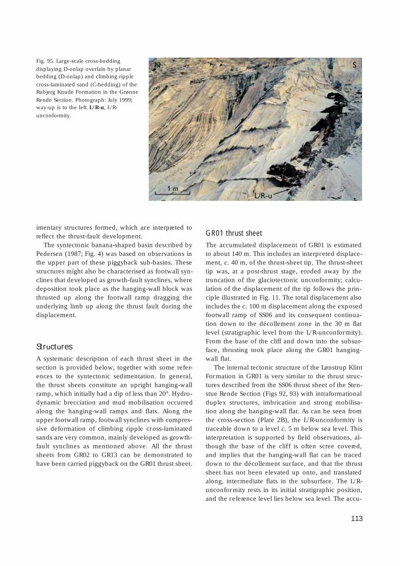
113
imentary structures formed, which are interpreted toreflect the thrust-fault development.
The syntectonic banana-shaped basin described byPedersen (1987; Fig. 4) was based on observations inthe upper part of these piggyback sub-basins. Thesestructures might also be characterised as footwall syn-clines that developed as growth-fault synclines, wheredeposition took place as the hanging-wall block wasthrusted up along the footwall ramp dragging theunderlying limb up along the thrust fault during thedisplacement.
StructuresA systematic description of each thrust sheet in thesection is provided below, together with some refer-ences to the syntectonic sedimentation. In general,the thrust sheets constitute an upright hanging-wallramp, which initially had a dip of less than 20°. Hydro-dynamic brecciation and mud mobilisation occurredalong the hanging-wall ramps and flats. Along theupper footwall ramp, footwall synclines with compres-sive deformation of climbing ripple cross-laminatedsands are very common, mainly developed as growth-fault synclines as mentioned above. All the thrustsheets from GR02 to GR13 can be demonstrated tohave been carried piggyback on the GR01 thrust sheet.
GR01 thrust sheet
The accumulated displacement of GR01 is estimatedto about 140 m. This includes an interpreted displace-ment, c. 40 m, of the thrust-sheet tip. The thrust-sheettip was, at a post-thrust stage, eroded away by thetruncation of the glaciotectonic unconformity; calcu-lation of the displacement of the tip follows the prin-ciple illustrated in Fig. 11. The total displacement alsoincludes the c. 100 m displacement along the exposedfootwall ramp of SS06 and its consequent continua-tion down to the décollement zone in the 30 m flatlevel (stratigraphic level from the L/R-unconformity).From the base of the cliff and down into the subsur-face, thrusting took place along the GR01 hanging-wall flat.
The internal tectonic structure of the Lønstrup KlintFormation in GR01 is very similar to the thrust struc-tures described from the SS06 thrust sheet of the Sten-stue Rende Section (Figs 92, 93) with intraformationalduplex structures, imbrication and strong mobilisa-tion along the hanging-wall flat. As can be seen fromthe cross-section (Plate 2B), the L/R-unconformity istraceable down to a level c. 5 m below sea level. Thisinterpretation is supported by field observations, al-though the base of the clif f is often scree covered,and implies that the hanging-wall flat can be traceddown to the décollement surface, and that the thrustsheet has not been elevated up onto, and translatedalong, intermediate flats in the subsurface. The L/R-unconformity rests in its initial stratigraphic position,and the reference level lies below sea level. The accu-
Fig. 95. Large-scale cross-bedding
displaying D-onlap overlain by planarbedding (D-onlap) and climbing ripple
cross-laminated sand (C-bedding) of theRubjerg Knude Formation in the Grønne
Rende Section. Photograph: July 1999;way-up is to the left. L/R-u, L/R-
unconformity.
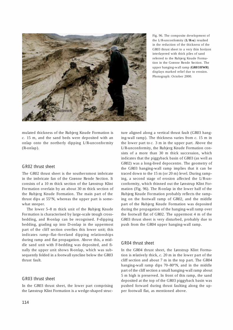
114
mulated thickness of the Rubjerg Knude Formation isc. 15 m, and the sand beds were deposited with anonlap onto the northerly dipping L/R-unconformity(R-onlap).
GR02 thrust sheet
The GR02 thrust sheet is the southernmost imbricatein the imbricate fan of the Grønne Rende Section. Itconsists of a 10 m thick section of the Lønstrup KlintFormation overlain by an about 30 m thick section ofthe Rubjerg Knude Formation. The main part of thethrust dips at 55°N, whereas the upper part is some-what steeper.
The lower 5–8 m thick unit of the Rubjerg KnudeFormation is characterised by large-scale trough cross-bedding, and R-onlap can be recognised. F-dippingbedding, grading up into D-onlap in the uppermostpart of the clif f section overlies this lower unit; thisindicates ramp–flat–foreland dipping relationshipsduring ramp and flat propagation. Above this, a mid-dle sand unit with F-bedding was deposited, and fi-nally the upper unit shows R-onlap, which was sub-sequently folded in a footwall syncline below the GR03thrust fault.
GR03 thrust sheet
In the GR03 thrust sheet, the lower part comprisingthe Lønstrup Klint Formation is a wedge-shaped struc-
ture aligned along a vertical thrust fault (GR03 hang-ing-wall ramp). The thickness varies from c. 15 m inthe lower part to c. 3 m in the upper part. Above theL/R-unconformity, the Rubjerg Knude Formation con-sists of a more than 30 m thick succession, whichindicates that the piggyback basin of GR03 (as well asGR02) was a long-lived depocentre. The geometry ofthe GR03 hanging-wall ramp implies that it can betraced down to the 15 m (or 20 m) level. During ramp-ing, a second stage of erosion affected the L/R-un-conformity, which thinned out the Lønstrup Klint For-mation (Fig. 96). The R-onlap in the lower half of theRubjerg Knude Formation probably reflects the ramp-ing on the footwall ramp of GR02, and the middlepart of the Rubjerg Knude Formation was depositedduring the propagation of the hanging-wall ramp overthe footwall flat of GR02. The uppermost 4 m of theGR03 thrust sheet is very disturbed, probably due topush from the GR04 upper hanging-wall ramp.
GR04 thrust sheet
In the GR04 thrust sheet, the Lønstrup Klint Forma-tion is relatively thick, c. 20 m in the lower part of thecliff section and about 7 m in the top part. The GR04hanging-wall ramp dips 70–80°N, and in the middlepart of the cliff section a small hanging-wall ramp about5 m high is preserved. In front of this ramp, the sanddeposited at the top of the GR03 piggyback basin waspushed forward during thrust faulting along the up-per footwall flat, as mentioned above.
Fig. 96. The composite development of
the L/R-unconformity (L/R-u) resultedin the reduction of the thickness of the
GR03 thrust sheet to a very thin horizoninterlayered with thick piles of sand
referred to the Rubjerg Knude Forma-tion in the Grønne Rende Section. The
upper hanging-wall ramp (GR03HWR)displays marked relief due to erosion.
Photograph: October 2000.
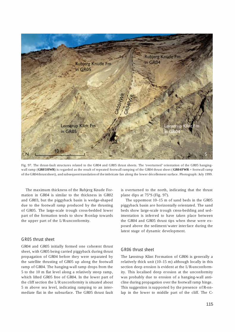
115
The maximum thickness of the Rubjerg Knude For-mation in GR04 is similar to the thickness in GR02and GR03, but the piggyback basin is wedge-shapeddue to the footwall ramp produced by the thrustingof GR05. The large-scale trough cross-bedded lowerpart of the formation tends to show R-onlap towardsthe upper part of the L/R-unconformity.
GR05 thrust sheet
GR04 and GR05 initially formed one coherent thrustsheet, with GR05 being carried piggyback during thrustpropagation of GR04 before they were separated bythe satellite thrusting of GR05 up along the footwallramp of GR04. The hanging-wall ramp drops from the5 to the 10 m flat level along a relatively steep ramp,which lifted GR05 free of GR04. In the lower part ofthe cliff section the L/R unconformity is situated about5 m above sea level, indicating ramping to an inter-mediate flat in the subsurface. The GR05 thrust fault
is overturned to the north, indicating that the thrustplane dips at 75°S (Fig. 97).
The uppermost 10–15 m of sand beds in the GR05piggyback basin are horizontally orientated. The sandbeds show large-scale trough cross-bedding and sed-imentation is inferred to have taken place betweenthe GR04 and GR05 thrust tips when these were ex-posed above the sediment/water interface during thelatest stage of dynamic development.
GR06 thrust sheet
The Lønstrup Klint Formation of GR06 is generally arelatively thick unit (10–15 m) although locally in thissection deep erosion is evident at the L/R-unconform-ity. This localised deep erosion at the unconformitywas probably due to erosion of a hanging-wall anti-cline during propagation over the footwall ramp hinge.This suggestion is supported by the presence of R-on-lap in the lower to middle part of the cliff. The C-
Fig. 97. The thrust-fault structures related to the GR04 and GR05 thrust sheets. The ‘overturned’ orientation of the GR05 hanging-wall ramp (GR05HWR) is regarded as the result of repeated footwall ramping of the GR04 thrust sheet (GR04FWR = footwall ramp
of the GR04 thrust sheet), and subsequent translation of the imbricate fan along the lower décollement surface. Photograph: July 1999.
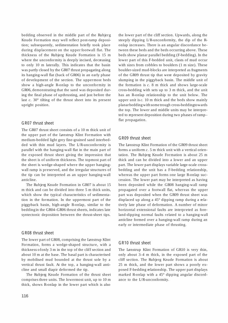
116
bedding observed in the middle part of the RubjergKnude Formation may well reflect post-ramp deposi-tion; subsequently, sedimentation briefly took placeduring displacement on the upper footwall flat. Thethickness of the Rubjerg Knude Formation is 15 mwhere the unconformity is deeply incised, decreasingto only 10 m laterally. This indicates that the basinwas partly closed by the GR07 thrust propagating alongits hanging-wall flat (back of GR06) in an early phaseof development of the section. The uppermost bedsshow a high-angle R-onlap to the unconformity inGR06, demonstrating that the sand was deposited dur-ing the final phase of upthrusting, and just before thelast c. 30° tilting of the thrust sheet into its presentupright position.
GR07 thrust sheet
The GR07 thrust sheet consists of a 10 m thick unit ofthe upper part of the Lønstrup Klint Formation withmedium-bedded light grey fine-grained sand interbed-ded with thin mud layers. The L/R-unconformity isparallel with the hanging-wall flat in the main part ofthe exposed thrust sheet giving the impression thatthe sheet is of uniform thickness. The topmost part ofthe sheet is wedge-shaped where the upper hanging-wall ramp is preserved, and the irregular structures ofthe tip can be interpreted as an upper hanging-wallanticline.
The Rubjerg Knude Formation in GR07 is about 15m thick and can be divided into three 5 m thick units,which show the typical characteristics of sedimenta-tion in the formation. In the uppermost part of thepiggyback basin, high-angle R-onlap, similar to thebedding in the GR04–GR06 thrust sheets, indicates latesyntectonic deposition between the thrust-sheet tips.
GR08 thrust sheet
The lower part of GR08, comprising the Lønstrup KlintFormation, forms a wedge-shaped structure, with athickness of only 3 m in the top of the clif f section andabout 10 m at the base. The basal part is characterisedby mobilised mud bounded at the thrust sole by avertical thrust fault. At the top, a hanging-wall anti-cline and small diapir deformed the tip.
The Rubjerg Knude Formation of the thrust sheetcomprises three units. The lowermost unit, up to 10 mthick, shows R-onlap in the lower part which is also
the lower part of the cliff section. Upwards, along thesteeply dipping L/R-unconformity, the dip of the R-onlap increases. There is an angular discordance be-tween these beds and the beds occurring above. Thesebeds show planar parallel bedding (F-bedding). In thelower part of this F-bedded unit, clasts of mud occurwith sizes from cobbles to boulders (1 m size). Theseboulder-sized mud-blocks are interpreted as fragmentsof the GR09 thrust tip that were deposited by gravityslumping in the piggyback basin. The middle unit ofthe formation is c. 8 m thick and shows large-scalecross-bedding with sets up to 3 m thick, and the unithas an R-onlap relationship to the unit below. Theupper unit is c. 10 m thick and the beds show mainlyplanar bedding with some trough cross-bedding towardsthe top. The lower and middle units may be interpre-ted to represent deposition during two phases of ramp–flat propagation.
GR09 thrust sheet
The Lønstrup Klint Formation of the GR09 thrust sheetforms a uniform c. 5 m thick unit with a vertical orien-tation. The Rubjerg Knude Formation is about 25 mthick and can be divided into a lower and an upperpart. The lower part displays variable large-scale cross-bedding and the unit has a F-bedding relationship,whereas the upper part forms one large R-onlap suc-cession. The lower part may be interpreted as havingbeen deposited while the GR08 hanging-wall ramppropagated over a footwall flat, whereas the upperpart was deposited when the GR09 thrust sheet wasdisplaced up along a 45° dipping ramp during a rela-tively late phase of deformation. A number of minorhorizontal extensional faults are interpreted as fore-land-dipping normal faults related to a hanging-wallanticline formed over a hanging-wall ramp during anearly or intermediate phase of thrusting.
GR10 thrust sheet
The Lønstrup Klint Formation of GR10 is very thin,only about 3–4 m thick, in the exposed part of thecliff section. The Rubjerg Knude Formation is about25 m thick, and the lower part shows a poorly ex-posed F-bedding relationship. The upper part displaysmarked R-onlap with a 45° dipping angular discord-ance to the L/R-unconformity.

117
GR11 thrust sheet
The GR11 thrust sheet is irregularly orientated, but ismainly vertical in the upper frontal part. In GR11, theLønstrup Klint Formation has a uniform thickness of10 m, consisting of medium-bedded light coloured sandinterbedded with thin mud layers situated above thesteeply dipping hanging-wall flat. The Rubjerg KnudeFormation is generally not well exposed due to sandscree, but has a thickness of about 15 m.
GR12 thrust sheet
A large part of the GR12 thrust sheet is covered bysand scree, and detailed data from this part of theGrønne Rende Section are limited. The Lønstrup KlintFormation forms a c. 5 m thick unit of sand domi-nated by thick-bedded turbidites, as is typical of theupper part of the formation. The Rubjerg Knude For-mation is more than 20 m thick and displays the typ-ical depositional features of the formation. However,it should be noted that the L/R-unconformity in GR12,as is the case in GR11, has been lifted up to an eleva-tion of 15–20 m a.s.l.; this indicates that these sheetspropagated over an upper flat, probably composed oftwo stacked duplex segments of GR06 and GR08 inthe subsurface.
GR13 thrust sheet
The GR13 thrust sheet is also mainly covered by sandscree at the base of cliff. However, exposures in theupper part of the cliff reveal a rather complex struc-ture. The Lønstrup Klint Formation of the thrust sheetis very thin, and in places only the unconformity isobserved; it can thus be difficult to recognise wherethe stratigraphic unconformity is preserved and whereit has been completely replaced by the thrust fault,which is now vertically orientated. Furthermore, theRubjerg Knude Formation has been subjected to su-perimposed folding. The thickness of the piggybackbasin deposits in GR13 is more than 30 m and fourunits of the Rubjerg Knude Formation are differenti-ated. Unit 1 is about 5–6 m thick, and appears in thefrontal and upper part of the piggyback basin; it ischaracterised by large-scale cross-bedding as well asplanar parallel stratification. Towards the trailing endof the thrust sheet, the R-onlap in unit 1 grades upinto unit 2, which is folded into a set of overturned
folds, originally with a horizontal axial plane, but nowre-orientated into an upright position; the overturnedfolds deform the bedding in unit 1. Unit 3 is charac-terised by steeply dipping large-scale foresets that weredeposited over the recumbent folds. Finally unit 4,about 7 m thick, is mainly planar-bedded and waspushed in front of a hanging-wall ramp of the frontalthrust sheet in the Rubjerg Fyr Section.
Interpretation of structural developmentTwo types of interpretations are considered prior tothe further description of the structural development:(1) in order to estimate the displacement, a geometricconstruction has been made for each thrust-sheet tipsubsequently eroded away at the glaciotectonic un-conformity (Fig. 11), and (2) the position of the L/R-unconformity below the screes has been constructedfrom successive approximations (Plate 1). Interpreta-tion of the extent of the thrust tips was carried out asa triangular construction with a best-fit of the inter-section of the unconformity and the thrust plane (seeFig. 11). Where these surfaces (lines in the 2-D con-structions in Fig. 11) were obscured, the constructionwas guided by the assumption that the acute angle isclose to 18°, which from experience is a general ini-tial thrust ramp angle. According to this geometricalreconstruction, the average displacement of each thrustsheet is about 70 m.
The general impression is that the thrusting of thetwelve imbricate sheets in the Grønne Rende fan-struc-ture was broadly contemporaneous. If the experiencefrom the Ulstrup Section near the foreland is takeninto consideration, one would expect a long coher-ent thrust sheet initially displaced along the upper flatlevel at 10 m stratigraphic depth (from the L/R-uncon-formity). From this detachment level, the imbricatethrust-fault fan propagated with fairly equal spacing,and the thrusting progressed during sedimentation ofthe Rubjerg Knude Formation. However, there are twopositions where the piggyback basin has a thinnerdepositional fill, namely the basin on GR01 and onGR06/GR07. Thus, the first longer displacement alongan upper footwall flat took place on the back of GR06and GR01, subsequently leaving a trailing-end duplexsegment below the 10 m detachment level at the rearof GR06 as well as at the end of GR01. When abouthalf of the displacement along the GR06 had takenplace, the level of detachment started to root down tothe 20 m flat level, such that the trailing duplex seg-

118
ment of GR06 was free to move along intermediateramps. Thus, if about 20 m of the displacement oneach of the GR07–GR13 thrusts is accumulated, itamounts to a total displacement of about 140 m forthe GR06 trailing segment (GR06u). It is therefore ar-gued that the GR06u segment started to ramp in themiddle phase of thrust propagation, which is reflect-ed in a foreland-dipping tilt in the GR13 basin thatcreated the recumbent folding.
The sequence in ramping follows three angularmodes: initial ramping along an angle of about 18°,intermediate ramping along an angle of 30°, and finalramping at close to 45°. However, ramping will neverbe initiated at an angle of 90°, so the problem is howto explain the vertically orientated thrust faults.
The first c. 20° ramp is given by the upper ramping,and progressive ramping will result in a 36–45° tilt.This would result in progressive steepening of thetilting from south to north, however, which is clearlynot the case. It is suggested, therefore, that the GR01thrust jumped down to the décollement level at the30 m stratigraphic depth, and that this caused the re-orientation during the final displacement of GR01.Thus, when the imbricate fan with ramp angles up to40° was carried along with the lower GR01 thrust-sheet segment (GR01u) towards the 45° inclined frontalramp, all the thrust sheets were subsequently tilteddue to a common megascopic shear. The combina-tion of this large-scale shear tilt and the accumulatedramp steepening is very well illustrated in the GR05thrust sheet, which was separated from GR04 along asatellite thrust fault. The hanging-wall ramp of GR04was fixed with a c. 75° steep dip. Consequently thehanging-wall ramp of GR05, which was carried piggy-back on GR04, ended up in an overturned position(dip of about 75°S).
In balancing the Grønne Rende Section, one prob-lem remains to be solved, namely the fate of the trail-ing-end segment of GR06. However, this is a minorproblem compared to the space problem created bythe GR01 thrusting along the 30 m décollement level.The trailing-end thrust-sheet segment of GR01u (aduplex sheet created between the 30 m and the 20 mflat level) is considered below under the structural anddynamic analysis of the Rubjerg Knude Fyr and Stor-torn Sections.
Rubjerg Knude Fyr SectionThis section is situated below the Rubjerg Knude Fyr,and makes up the highest part of the cliff (see coverillustration). The cliff section below the lighthousecomprises the thickest thrust sheets, which are rampedup to the highest footwall flat level. This means thatthrust sheets with a décollement level at a depth ofabout 35 m are ramped up and thrust along a flat atthe 10 m deep level.
Normal fault structures similar to the Brede Rendenormal fault also appear in the Rubjerg Knude FyrSection. The tip of the prominent thrust sheet in thecentral part of the section was dropped down into thepiggyback basin in front of the thrust fault, and sub-sequently buried by sediments of the Rubjerg KnudeFormation. Structural elements related to the hang-ing-wall ramp are well illustrated in this section.
Tectonic architectureThe Rubjerg Knude Fyr Section comprises six rela-tively thick thrust sheets annotated RF01–RF06. Theleading-edge thrust and hanging-wall ramp-and-flatof RF01 terminate all the imbricates in the GrønneRende Section. To the north, the section is boundedby the footwall ramp of RF06 that coincides with thehanging-wall ramp of the frontal thrust sheet in theStorntorn Section. The thickness of the thrust sheetsis bounded by the 20 m flat level in the southern part,and increases in the northern part down to the 30 mflat. All the thrust sheets in the section are thrust overthe lower duplex segment of GR06 and GR01. Trans-lation along an intermediate flat is indicated by thedominant position of the L/R-unconformity at 20 m a.s.l.
The RF01 and RF02 thrust sheets make up an easilyrecognisable thrust sheet pair that can also be locatedon the geological cross-section constructed by Jessen(1918; Fig. 98). The similarity of the remaining part ofthe Rubjerg Knude Fyr Section to Jessen’s cross-sec-tion is not so obvious, probably due to the interven-ing 80 years of cliff erosion and the present poor ex-posure of the section due to extensive sand scree.The dips of the footwall ramps are about 60°. Theangle between the L/R unconformity and the thrustsis about 30°, which means that the thrusts have beenrotated about 30° during ramp propagation in the sub-surface. This is illustrated by the angular relationshipbetween the L/R unconformity in RF01 and the foot-wall ramp of RF02. The thrust-fault displacement ofRF01 and RF02 ranges from 50–65 m.
119
At the tip of RF01, a 25 m long upper hanging-wallflat is preserved. Below this, a 5–7 m thick sheet com-prising the top of the GR13 piggyback basin occurs.This upper footwall flat segment of GR13 was dis-placed an unknown distance (25–50 m) forwards infront of the upper hanging-wall ramp of RF01.
The Rubjerg Knude Formation in RF02 is poorlyexposed due to sand scree at the base of the cliff, butit is interpreted to be 20 m thick. From the L/R-uncon-formity up to the overlying thrust fault, the thicknessof the piggyback basin is about 40 m. However, it isinferred that a thrust fault situated in the middle partof the basin is responsible for repetition of the Ru-bjerg Knude Formation, and that a normal fault simi-lar to the BRNF, is located in the upper levels of theRF02 sheet. The normal fault is asymptotic, fading outtowards the L/R-unconformity in the RF02 thrust sheet.
The RF03 thrust sheet is a small sheet with a trun-cation structure. The nose of this thrust sheet wasobviously exposed to normal faulting at an early stageof development (Fig. 99). After fault displacement, the
RF03 tip was eroded away and the top of the thrustsheet erosionally truncated to form an unconformity,which cut off the sheet at a very steep angle (> 70°).The normal fault at the tip of RF03 is the first of twonormal faults displaced down on to the piggybackbasin of RF02. In the second phase of normal fault-ing, the c. 45 m long tip of the RF04 thrust sheet wasdisplaced c. 35 m down a normal fault plane (Fig.100), which had an angle of 70–90° relative to thethrust fault and the L/R-unconformity of RF04. Thenormal faulting may have been initiated by differen-tial translation of hanging-wall ramps along interme-diate flats related to one or more subsurface duplexsegments. In a late phase of thrust faulting, the trailingpart of RF04 was thrust up over the piggyback basinof RF04/RF03/RF02, which brought the nearly 45° dip-ping lower hanging-wall ramp of RF04 into contactwith the footwall ramp of the displaced tip of RF04.The final phase of fault-bend folding tilted this rampinto a 70°S dipping position.
The RF05 and RF06 thrust sheets were thrust up
Fig. 98. The thrust sheet pair exposed below the Rubjerg Knude Fyr. To the right, the RF01 thrust sheet is thrust faulted along its
hanging-wall ramp (RF01HWR) along the footwall ramp in the trailing end of the Grønne Rende Section. RF01 forms the footwall
block for the propagation of the hanging-wall ramp of RF02 (RF02HWR). Note the elevated position of the L/R-unconformityindicating that the thrust sheets were thrusted up on duplex segments in the subsurface. Photograph: July 1999.

120

121
from the 30 m décollement level. The hanging-wallflat of RF06 rests on the upper flat of RF05, where nodeposits of the Rubjerg Knude Formation have beenrecognised. Thus the two thrust sheets occur as a blockof Lønstrup Klint Formation 60 m thick, separated inthe middle by a thrust fault. The L/R-unconformity inthe RF06 sheet is located at about 10–15 m above sealevel. Thus, the RF06 sheet was faulted up on an in-
termediate flat above the trailing edge of RF05, prob-ably while both were transported along the lower foot-wall flat on top of the lower trailing duplex segmentof the Grønne Rende Section.
Sedimentary unitsIn the Rubjerg Knude Fyr Section, the lower stratigra-phic levels of the Lønstrup Klint Formation are exposed,although they are commonly deformed either by mud-mobilisation or thrust-fault shearing. The Rubjerg Knu-de Formation above is poorly exposed, partly due tosand scree derived in part from the formation itself,and partly from the up to 50 m high sand dunes abovethe cliff. No further description of the formations isgiven here.
Facing page – upper:
Fig. 99. Normal faults displacing the top of the RF03 thrustsheet in the Rubjerg Knude Fyr Section. Note the footwall
syncline folded below the hanging-wall ramp at the top ofthe cliff section. Photograph: June 1984.
Facing page – lower:
Fig. 100. Normal fault (NF) displacing the tip of the RF04thrust sheet, which prior to normal faulting was thrusted
along the hanging-wall flat of RF04 (RF04HWF). Photograph:July 1994.
Fig. 101. Thrust-fault brecciation related to the lower hanging-wall ramp and flat in the Rubjerg Knude Fyr Section. The brecciation
fabric that is typical of the fine-grained sand turbidites and laminated clayey muds (compare with primary sedimentary features inFigs 22, 23) was produced by low-angle anastomosing shearing. Photograph: September 1985.

122
StructuresTwo types of deformation alter the primary sedimen-tary architecture of the Rubjerg Knude Fyr Section. Thefirst type is anastomosing thrust-fault brecciation re-lated to the zone above the hanging-wall ramp withfine-grained turbidites. The second type is the mud-mobilisation and mesoscopic-scale polydiapirism,which is common in the clay-rich lower part of thethrust sheets. These deformation types have to beconsidered in the evaluation of the balance calcula-tion. Only the anastomosing thrust-fault brecciationwill be further described in this section; descriptionsof diapirism are given under the Kramrende, BredeRende, Sandrende and Moserende Sections.
Anastomosing thrust-fault brecciation
The most significant mesoscopic-scale structure rec-ognised in the Rubjerg Knude Fyr Section is related tothrust-fault brecciation in the lower part of the Løn-strup Klint Formation. The brecciation fabric that istypical of the fine-grained turbidites and laminatedclayey muds was created by low-angle anastomosingshearing. The shear surfaces and thrust-fault displace-ments are located in the clay-rich laminae, whereasthe segments bounded by the anastomosing fracturesconsist of silty mud lithologies (Fig. 101). The brecci-ation extends from the lower hanging-wall ramp-and-flat up to 10 m above the sole of the sheets.
The anastomosing thrust faulting indicates that sig-nificant dif ferential movements developed in the sub-surface during thrust-fault propagation, which illus-trates the nature of the displacement-related shearingand which may account for some of the volume prob-lems arising from construction of the balanced cross-section.
Interpretation of structural developmentThe compression (shortening) in the Rubjerg KnudeFyr Section is about 48%, calculated from the meas-ured length of the section of 270 m (= L
1) and the
balanced length of about 520 m (= L0). This implies
that the thrust sheets in the section have been dis-placed upwards at the ramp originally situated at thetrailing end of RF04 and transported to the position ofthe footwall ramp of GR13. The lower flat is still the foot-wall flat on top of the lower duplex segment of the
Grønne Rende Section. Thus, a considerable amount oflateral translation is apparent in the Rubjerg KnudeFyr Section.
The appearance of the normal fault with down-fault-ed noses of the RF03 and RF04 sheets indicates thatdifferential movements, including duplex developmentof the GR01–GR06 lower segments, may have occurredto create the foreland-dipping features in the RF02–RF03 piggyback basin.
The interesting structure in RF05 is the lower hang-ing-wall ramp, which has to correspond to a footwallramp at the trailing end of RF04. The footwall ramp-ing probably also included propagation along a foot-wall ramp of a lower duplex segment of RF04 (RF04u).The present orientation of the RF05 lower hanging-wall ramp is more or less vertical, indicating threesteps of ramping. The final tilting was due to the ram-ping of the upper footwall ramp of GR13, the middlephase of ramping was up along the footwall ramp ofthe piggyback basin in the normal fault displaced RF04,and the initial ramping was probably a complex pro-pagation over several smaller ramp-steps that separa-ted RF06 from RF05.
The uppermost part of RF06 shows a marked to-pography, indicating that at an early phase of defor-mation it was elevated up to a level of erosion, beforesubsequent sedimentation. This sedimentation was pro-bably of relatively short duration before over-thrustingof the Stortorn Section trapped the piggyback basin.
Stortorn SectionStortorn is the name of the very steep and muddy cliffin the central part of the Rubjerg Knude cliff section.On old drawings of the beach and the coastal cliff,Stortorn is depicted as a steep, wild looking castle-like cliff in the distant horizon, emphasising the ro-mantic scenery of this remote place (e.g. engravingby C. Neumann 1884, reproduced in Vendsyssel nu ogda, 1981). In recent times, the cliff has also been thelocation of major landslides, which in some cases trav-elled more than 100 m out into the sea. In general,the sea reaches close up to the vertical cliff, and dueto the muddy and slippery cliff surfaces and the claypavement in the zone of breakers, it is the most diffi-cult place to pass along the coast.
In the Stortorn Section, the deepest level of thrust-ing occurs where the décollement zone is located at adepth of 40 m stratigraphically below the referencesurface of the L/R-unconformity, which is about 45 m
123
below sea level. From this deep level, the thrust sheetswere elevated up to the exposed position in the cliffsection. Coinciding with this, the thrust sheets con-tain the deepest levels of the stratigraphy, and bedsof marine and glaciomarine clay can be identified bythe occurrences of arctic marine fossils. Moreover, theStortorn Section contains the key features for under-standing the structural and dynamic problems of theadjacent Rubjerg Knude Fyr and Grønne Rende Sec-tions. The key features are flat-lying duplex complex-es formed by ramping up of the relatively long, lowerthrust-sheet segments onto a high flat level. This isreflected in an elevation of the L/R-unconformity upto a height of c. 40 m above sea level in the cliff sec-tion.
Tectonic architectureThe Stortorn Section is divided into ten thrust sheetsannotated ST01–ST10. The southern boundary of thesection is the frontal hanging-wall flat of ST01, whichcoincides with the footwall ramp of the RF06 thrustsheet in the Rubjerg Knude Fyr Section. The northernboundary is the trailing footwall thrust of ST10 alongwhich the frontal hanging-wall ramp of the MoserendeSection was thrust.
The southernmost three thrust sheets form a sepa-rate group of high-level thrust sheets. The L/R uncon-formity is here situated at an elevation of 35–40 mabove sea level. The central part of the section isformed by a series of thick thrust sheets of clayey,partly mobilised, mud, which are situated above hid-den duplexes in the subsurface. This complex extendsabout 150 m along the cliff section at Stortorn. In thenorthern part of the section, upright mud diapir-dom-inated thrust sheets occur with complexly developedpiggyback basins.
ST01 thrust sheet
The southernmost thrust sheet in the Stortorn Section(ST01) is wedge-shaped, c. 160 m long, with an initial25° dip of the frontal hanging-wall ramp. The foot-wall ramp (FR06 trailing edge) dips at about 45°, whichcreates a problem in the balancing. It is obvious that asplint (or horse) corresponding to a triangle with anacute angle of 20° must be hidden somewhere in thedeeper structure. The trailing end of ST01 is 30 m thick.However, the Lønstrup Klint Formation is deeply erod-
ed in the central part of ST01, which truncates theL/R-unconformity.
ST02 thrust sheet
The ST02 thrust sheet was also elevated to a height of35–40 m in the cliff section. The hanging-wall ramp isvertical and forms a right-angle with the horizontalbedding in the piggyback basin of ST01. This indi-cates that final up-thrusting of the frontal hanging-wallramp took place in an upright position during sedi-mentation on the back of ST01. The ST02 thrust faultwas rotated at least three times before propagationup along the footwall ramp of ST01. The initial dip ofthis ramp was relatively steep, about 40°, as indicatedby the angle between the thrust fault and the beddingin the Lønstrup Klint Formation of ST01. Furthermore,the problem related to the change in ramp angle re-curs. In the balancing of the thrust structure, a splintvolume must be calculated for, corresponding to thetriangle created by the initial thrust angle and the fi-nal steeply inclined thrust fault.
ST03 thrust sheet
The ST03 thrust sheet is not elevated as much as ST01and ST02; the L/R-unconformity is only situated atabout 30 m above sea level. The Lønstrup Klint For-mation was deeply eroded before sedimentation inthe piggyback basin was initiated, probably due tomarked relief during ramp propagation.
ST04 thrust sheet
The lowest position of the L/R-unconformity in the ST04thrust sheet is about 13–15 m above sea level, whichdemonstrates a shallower level of ramping than in ST01–ST03. The 45° steeply dipping thrust fault betweenST03 and ST04 roots down to the décollement zoneand propagated up along the footwall ramps of thesubsurface duplex segments beyond ST01–ST03. Thedif ference between initial and final angle of rampingalso created a balancing problem for ST04. The fron-tal part of the hanging-wall ramp of ST04 only had adip of 18–20°, whereas the footwall ramp now dips atc. 45°. Therefore a splint (with an area of 630 m2 inthe cross-section) is envisaged in the subsurface. TheST04 ramping over this splint is interpreted as the rea-

124
son for the elevation of the L/R-unconformity up to c.15 m above sea level.
ST05 thrust sheet
The ST05 thrust sheet is one of the most importantstructures, not only in the Stortorn Section but also inthe Rubjerg Knude Glaciotectonic Complex as a whole.It involved thrusting of the deepest décollement lev-el, which introduced a complex framework due tothe large number of duplex segments involved. TheST05 thrust sheet was thrust up along the footwallramp of ST04. The dip of the thrust fault increasesfrom 35° at the beach level to 70° at the top of the cliffsection. The tip of the thrust sheet was finally dis-placed horizontally over the top of the piggyback basinof ST04. The thrust displacement along the hanging-wallthrust fault is estimated to be in the order of 90 m.
The Lønstrup Klint Formation of ST05 is dominat-ed by mud diapirism and polydiapiric structures up to5 m in vertical scale. In the middle part of the thrustsheet, where the thickness of the initially wedge-shaped frontal part was 20 m, a deeply eroded troughwas formed. The L/R-unconformity on the northernflank of this erosional depression is situated nearly 50m above sea level. This is about the highest elevationof the reference surface, and was caused by thrustduplication of the thrust sheet in the subsurface du-plex complex.
ST06 thrust sheet
The ST06 thrust sheet is poorly exposed and mud-mobilisation and internal diapirism obscure primarystructures. The thickness of the thrust sheet is up to40 m, measured from the frontal hanging-wall thrustup to a small pocket of Rubjerg Knude Formation sandthat forms the remnant of a piggyback basin. The front-al thrust is drawn with some uncertainty, because alarge part of it is penetrated by diapirism intrudingfrom the back of ST05. A minimum displacement of40 m is inferred, which is incorporated in the model-ling of the balanced cross-section. This implies a rath-er complex structural assemblage of the subsurfacelower duplex segments of ST05, ST06 and ST07.
ST07 thrust sheet
The ST07 thrust sheet is nearly vertically orientatedwith a frontal ramp rising from 70° to vertical, alongwhich a displacement of 28 m is estimated to haveoccurred. The L/R-unconformity surface is also steep-ly dipping, and is even overturned at the top. Thelower part of the thrust sheet is mainly covered byscree, but it is possible to trace the line of the uncon-formity down to the level of the beach in the cross-section. This implies that the thrust sheet has not beenthrust up to be displaced along an intermediate rampbut is only tilted due to the main ramping, first alongthe thrust fault of ST06 and finally on its own hang-ing-wall ramp. The ramping is also reflected in thedeposition in the piggyback basin where three super-posed angular discordances are recognised. The de-posits in the piggyback basin are c. 15 m thick; at thebase of the succession, the R-onlap starts with an an-gle of 45° and terminates with a 90° angle, indicatingdeposition in the basin while the thrust sheet wasvertically orientated. In the uppermost bed, minorslump folds are present, indicating the effect of theST08 thrust nose approaching from the north.
ST08 thrust sheet
A double ramp synclinal structure, similar to the oneoccurring in the piggyback basin of ST05, is recog-nised in thrust sheet ST08. The L/R-unconformity in-cises through the Lønstrup Klint Formation and downinto the thrust-fault surface of the hanging-wall ramp.The lateral distance between the ramps is only about25 m and the basin is less than 10 m deep. The sedi-ments in this piggyback basin show large-scale troughcross-bedding accentuated by synclinal folding. TheRubjerg Knude Formation covers a feature that repre-sents the erosional remnants of a detachment anti-cline on the northern limb of the basin. On the northside of this structure, the initial stratification abovethe L/R-unconformity shows clear R-onlap, corre-sponding to the inclination parallel to the tilt of thelower ramp. The unconformity is elevated up to 20 mabove sea level, indicating that the ST08 thrust sheetwas lifted up by at least two subsurface duplex seg-ments. These hidden segments are annotated ST08u1and ST08u2. The displacement along the footwall rampof ST08 is estimated at 78 m, mainly along the thrustfault dipping at 30°.

125
ST09 thrust sheet
The ST09 thrust sheet is a c. 30 m thick sheet bound-ed by a 60° dipping hanging-wall flat thrust up ontothe footwall ramp of ST08 back and the 60° dippingfootwall thrust fault of ST10, which truncates the ir-regular structures in the upper part of the thrust sheet.The displacement along the hanging-wall ramp is es-timated at c. 60 m. Although the Lønstrup Klint For-mation in ST09 is characterised by internal diapirism,the features of a hanging-wall anticline can be recog-nised at the top of the cliff section. During translationof two or more footwall ramps, an irregular synformformed and created the depocentre of a piggybackbasin. The L/R-unconformity is here elevated to 5–10m above sea level, corresponding to propagation uponto the ST08u2 duplex segment.
ST10 thrust sheet
The ST10 thrust sheet is about the same size as theST09 sheet, and also has steeply dipping boundingthrust faults. The most remarkable structure in the ST10thrust sheet is the structural complexity of the piggy-back basin. The L/R-unconformity forms an isoclinalrecumbent syncline, with the upper limb formed bythe mud-mobilised Lønstrup Klint Formation, and abovethis a minor synclinal trough appears. This structureis best described as a detachment anticline, whichdeveloped into a diapir with a reverse fault displacingthe northern limb of the structure into a mushroom-shaped structure, similar to the diapir in the SandrendeSection. At a late stage of thrusting, the piggybackbasin was rotated 60° and the diapir-developed de-tachment anticline collapsed into the recumbent struc-
Fig. 102. Isoclinal upright anticline
formed in the lower part of the LønstrupKlint Formation in the frontal part of the
Stortorn Section. The right limb of theanticline constitutes an imbricate duplex
formed by connecting thrust-fault splays(white dot-and-dash lines). The fold is
interpreted as a hanging-wall anticlinedeveloped during fault propagation and
successive imbricate stacking (comparewith Fig. 59). Photograph: August 2001.

126
ture. The L/R-unconformity is elevated up to 15–18 mabove sea level indicating a ramping of the ST08uduplex segment as well as the trailing segment of ST09.An estimated displacement of 73 m along the hang-ing-wall ramp of ST10 still leaves some subsurfacesegments to be balanced in the structure below theMoserende Section to the north.
Sedimentary unitsThe most important sedimentary feature in the Stor-torn Section is the exposure of the Stortorn Forma-tion, which is the lowermost stratigraphic level in-volved in the Rubjerg Knude Glaciotectonic Complex.The Stortorn Formation is located at the lower hang-ing-wall ramp of the ST05 thrust sheet, where it formsa duplex segment about 3–5 m thick at the base ofthe cliff. To date, it has not been possible to measurea sedimentological log of the formation at this locali-ty, partly because the formation is strongly shearedby anastomosing fractures, and partly because land-slide activity precludes more detailed stratigraphicdescription.
StructuresThe contact between mobilised, intrusive mud andstratified mud has been observed in many places, butthis characteristic is better illustrated in the MoserendeSection (see below). Anastomosing thrust faults andtectonic breccias occur commonly in the ST05 andST06 thrust sheets. However, due to the difficult fieldconditions, detailed investigations have not been car-ried out.
In the dark clayey mud of thrust sheet ST01, anupright nearly isoclinal anticline has been observed(Fig. 102). This fold is considered to represent a hang-ing-wall anticline that was subjected to an advancedstage of deformation during ramp propagation. Thisstage compares well with the model of duplex forma-tion described by Mitra & Sussman (1997), in whichthe growth of imbricates derived from successive con-necting splays results in steepening of antiformal stacksformed by fault-propagation folding of duplexes. Suc-cessive growth of duplex elements corresponds wellwith the interpretation presented below.
Interpretation of structural developmentThe cross-section (Plate 2B) provides a model for thestructures below the frontal part of the Stortorn Sec-tion, which requires four duplex segments forming aduplex complex, on top of which thrust sheets ST01,ST02 and ST03 have been thrust along the footwallflat. The structural interpretation of a duplex stackingof subsurface segments below the frontal part of theStortorn Section is based on two lines of evidence:(1) the missing balance of the lower segments relatedto the Grønne Rende Section, and (2) the high eleva-ted position of the L/R-unconformity in this part ofthe section. Thus the lower duplex complex in thefrontal part of the section is interpreted to representstacking of the trailing lower segment of GR01, al-though an alternative differential duplex-segment dis-placement is also possible.
From geometric considerations, it is evident thatthe 20 m and 30 m décollement levels must have beenpervasive throughout the proximal part of the thruststructure. Thus the duplex in the Stortorn Section con-sists of segments c. 10 m thick. Mobilisation and theinternal polydiapirism have obscured the boundariesof these segments, which are the lower and interme-diate footwall and hanging-wall flats respectively.However, in a model for reconstruction, these volumesare regarded as solid thrust sheet, i.e. the duplex seg-ments (represented by annotated areas in Plate 2). Inthe description and solution of the structural problemrelated to differential thrust faulting of the lower du-plex segments, three main types of fault-bend-foldedsegments are distinguished (Fig. 103).
Fig. 103. Schematic illustration of the three types of fault-bendfolding of duplex segments. Type 1 is referred to as an L-struc-
ture, type 2 as an S-structure and type 3 as a G-structure (Gchosen due to similarity with the Greek capital letter gamma
(Γ)). The footwall ramp dips at about 45°, the shortening be-tween the underlying footwall ramp and the overlying hang-
ing-wall ramp is 43%, the initial length (L0) of the thrust sheet is
c. 100 m, compared to a thrust-sheet thickness of 40 m, and a
thickness of 10 m for the individual duplex segments.

127
1. A duplex segment with one part of the segmentresting on the lower flat and the other parallel witha ramp (L-structure).
2. A duplex segment which has the trailing part par-allel with the lower flat, the intermediate part par-allel with a ramp, and the frontal part parallel withthe upper flat, thus giving the shape of a S.
3. A duplex segment with the trailing part of the seg-ment located parallel with the ramp and the front-al part parallel with the upper flat (Γ-structure).
The stacking of the duplex below the ST01, ST02 andST03 thrust sheets started when the lower segmentswere thrust up into the first type duplex bend duringramping towards the footwall ramp of RF06 (trailingend of the Rubjerg Knude Fyr Section). This probablymarked the end of the lateral translation along thelower flat levels and the initiation of stacking alongsteeply dipping thrust faults. This resulted in the rota-tion of all the previously formed structures and crea-ted the odd trough structures in the double ramp syn-clinal troughs. The final up-thrusting along steeplydipping thrust faults, which occurred contemporane-ously with the uppermost sedimentation in the piggy-back basins, was probably also contemporaneous withthe initiation of ramping of ST05 from the lowest level.One way to demonstrate this is to focus on the thrust-fault development of ST04. The ST04 thrust fault act-ed as the ramp that pushed on the trailing end of theduplex below ST01, ST02 and ST03. When the pushon this footwall ramp ended and the ST04 thrust sheetwas displaced up over the footwall ramp of ST03 itresulted in a shortening of 60%. The balanced lengthof ST04 is c. 200 m. Thus, the deep level ST05 rampmust be responsible for removing the 120 m lowerlong segment originally situated below ST04. There-fore about half of the ST04 thrust sheet also involvesthrusting down to the 40 m décollement level. In themodel, this ST04u segment was up-thrust to form afirst type of duplex-segment structure as the first low-er-segment imbricate in the subsurface of ST05.
However, it should be appreciated that a wholeunit of the thrust segments between the 20 m flat lev-el and 30 m décollement level has to be incorporatedin a differential thrust model. The simplest model forthis is to dissect the lower duplex segments into sheetswith an average length of c. 100 m. With each seg-ment bend in a type 2 ramping and with an equaldistribution of the frontal and trailing part on the up-per and lower flat, a series of double ramp synclineswould be created – comparable to the piggyback ba-
sins seen in ST10, ST09, ST08 and ST05. Similar basinsmay have existed in ST07 and ST06, but, if present,were removed by glaciotectonic truncation.
One of the central problems in describing the dy-namic development of the Rubjerg Knude Glaciotec-tonic Complex is understanding the formation of thelower ramp below the ST05 thrust sheet. It is knownthat the hanging-wall ramp is displaced up along theST05 thrust fault to be exposed in the cliff section atStortorn. However, a central question is – where wasthe footwall ramp for the lower hanging-wall ramp ofST05 situated?
According to the balanced cross-section, the ST05ramp should be situated about 7800 m from the front-al ramp in the Ulstrup Section and the footwall rampfor the lower ST05 ramping should be situated on thefar side (north) of the Lønstrup village. However, thisis not the position of the ST05 ramp. The distance to ahidden footwall ramp can only be fixed relative to thedisplacement in front of the lower ramp when it wasactivated during the change of décollement level fromthe 30 m level down to the 40 m flat level. The rela-tive displacement on the ST05 thrust fault is c. 90 m,measured from the tip of the thrust sheet along thehanging-wall ramp-and-flat down to the lower décol-lement surface. The main problem is related to thecompression documented south of the Stortorn Sec-tion. When this is considered in the balanced cross-section, it gives the geometric point for the hanging-wall ramp 7800 m from the frontal ramp in the UlstrupSection. However, the distance in the Rubjerg Knudecross-section from this ramp to the central part of theStortorn Section is only 3800 m. The solution to thisproblem is that the ramp was first formed after all theformer translation in the higher flat levels had passed.To understand this, one has to imagine that the upperpart of the Lønstrup Klint Formation at Grønne Rende(c. 3800 m from the frontal ramp in the Ulstrup Sec-tion) was originally situated above the Stortorn For-mation at the ST05 lower ramp. However, the rampwas first formed when the Rubjerg Knude Fyr Sectionwas displaced towards the Grønne Rende Sectionwhich itself was compressed against the Stenstue andSandrende Sections, which were all displaced overthe initial position of the Brede Rende and KramrendeSections. Only then was the ST05 lower ramp activat-ed, and the remaining northern part of the RubjergKnude Glaciotectonic Complex was displaced alongthe lowermost décollement zone.

128
Moserende SectionBetween Rubjerg Knude Fyr and Mårup Kirke, somesmall peat-bogs occur in depressions in the dune land-scape. This area of bog-filled depressions formerlyextended to the west, and the present cliff sectionintersects one of these bogs where peat (martørv) isexposed in the uppermost part of the cliff, similar tothe situation in the Martørv Bakker Section. A formergully here was named Moserende, and the name isadopted here for the section north of the StortornSection.
The most impressive feature in the Moserende Sec-tion is the syntectonic evolution of the piggybackbasins during polyphase thrust propagation (Fig. 104).Unusual sedimentological features are developed inthe Rubjerg Knude Formation, reflecting the tectonicdeformation, notably structures described as fissurestrata (Sjørring 1977). These are thin sedimentary bedsoccurring as discordantly incised wedges in ground-frozen sediment, here present in the growth-fault syn-clines related to the piggyback basins (Fig. 105).
Tectonic architectureThe Moserende Section comprises 13 relatively thickthrust sheets annotated MR01–MR13. In the section,three larger piggyback basins are preserved, one inthe frontal, southern part and two in the northern partof the section. The L/R-unconformity surface at thebase of the piggyback basins was elevated to variouslevels in the cliff section, reflecting the differentiatedtype of ramping throughout the section.
The leading-edge thrust in the Moserende Sectionis the hanging-wall ramp of MR01, which coincideswith the footwall thrust fault on the back of the ST10thrust sheet. To the north, the section is bounded bythe hanging-wall thrust at the base of the c. 40 mthick MK01 thrust sheet, which forms the southern frontof the Mårup Kirke Section. The MK01 thrust sheetwas thrust up along a steeply dipping footwall rampand subsequently displaced over the upper footwallflat on top of the piggyback basin of MR13 in thenorthernmost part of the Moserende Section.
It should be noted that the main frontal part (top-
Fig. 104. The piggyback basin of the MR02 thrust sheet. A sequentially developed growth-fault footwall syncline was formed below
the hanging-wall ramp of MR03 (MR3HWR ). Note the fissure strata cross-cutting the bedding (arrow) in the growth-fault footwallsyncline. Photograph: June 1984.
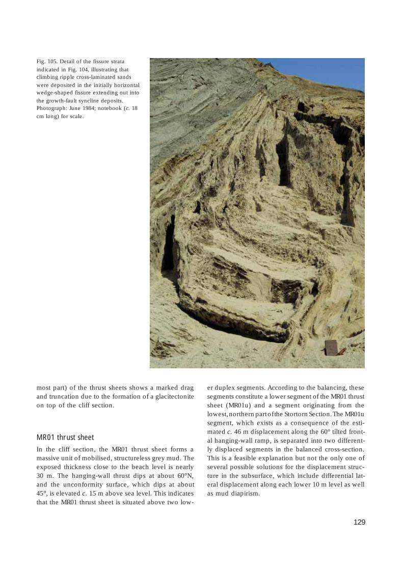
129
most part) of the thrust sheets shows a marked dragand truncation due to the formation of a glacitectoniteon top of the cliff section.
MR01 thrust sheet
In the cliff section, the MR01 thrust sheet forms amassive unit of mobilised, structureless grey mud. Theexposed thickness close to the beach level is nearly30 m. The hanging-wall thrust dips at about 60°N,and the unconformity surface, which dips at about45°, is elevated c. 15 m above sea level. This indicatesthat the MR01 thrust sheet is situated above two low-
er duplex segments. According to the balancing, thesesegments constitute a lower segment of the MR01 thrustsheet (MR01u) and a segment originating from thelowest, northern part of the Stortorn Section. The MR01usegment, which exists as a consequence of the esti-mated c. 46 m displacement along the 60° tilted front-al hanging-wall ramp, is separated into two different-ly displaced segments in the balanced cross-section.This is a feasible explanation but not the only one ofseveral possible solutions for the displacement struc-ture in the subsurface, which include differential lat-eral displacement along each lower 10 m level as wellas mud diapirism.
Fig. 105. Detail of the fissure strata
indicated in Fig. 104, illustrating thatclimbing ripple cross-laminated sands
were deposited in the initially horizontalwedge-shaped fissure extending out into
the growth-fault syncline deposits.Photograph: June 1984; notebook (c. 18
cm long) for scale.

130
MR02 thrust sheet
The MR02 thrust sheet is nearly 40 m thick and isdominated by mud mobilisation and internal chaoticstructures reflecting polydiapirism and internal flow.The sheet is divided internally by a thrust-fault zonewith dif ferential thrust movements, which could beinterpreted as a separation of the sheet into two indi-vidual thrust sheets. However, as the segments arenot separated by a piggyback basin they are regardedas a single amalgamated sheet.
The displacement along the hanging-wall ramp isthe same order of magnitude as for MR01 (c. 47 m)and the ramp is divided into an upper low-angle partwith an initial dip of only 20° and a lower steeplydipping part with an initial ramp-angle of about 45°.Due to subsequent rotation, the upper part of the rampis now orientated vertically while the lower part has asteep listric dip to the south. The footwall ramp (up-per part of MR01) has an initial dip of 45°, which cre-ates a space problem in balancing the section andmakes it necessary to introduce a splint segment be-tween MR01 and MR02 in the subsurface. The splintwas probably sheared and squeezed out and is likelyto have been included in the general mud mobilisa-tion. However, it is included in the balanced profilein order to deal with the ramp-angle-space problem(Plate 2).
The geometry of the L/R-unconformity at the topof the Lønstrup Klint Formation in the MR02 thrustsheet is very irregular with a peculiar c. 8 m high ob-stacle. This is very similar to the structure in the ST08thrust sheet in the Stortorn Section. It was probablyformed by a detachment anticline on the northern flankof the piggyback basin in the external part of the MR02thrust sheet, where it was subsequently buried by theRubjerg Knude Formation sand. The unconformity iselevated about 5 m above sea level, indicating thatthe MR02 thrust sheet has only stepped up one levelof the lower segments from where it is bent up alongits hanging-wall ramp. The detachment anticline wasprobably formed during the ramping of this lowersegment.
MR03 thrust sheet
The Rubjerg Knude Formation in the piggyback basinon top of MR02 and MR03 is here envisaged as a sin-gle large basin situated in the frontal part of the Mo-serende Section. The basin extends about 70 m along
the cliff section. Three upright standing peaks repre-sent the tips of three small thrust sheets that disturbedthe basin by small displacements. These thrust sheetsrepresent imbricates in the uppermost part of the MR03thrust sheet. Since the main part of the MR03 thrustsheet can be viewed as one large sheet subjected to asingle mode of displacement, the three imbricates arereferred to as MR03a, MR03b and MR03c.
The L/R-unconformity in MR03b and MR03c can betraced down below sea level, indicating that the mainpart of MR03 was displaced along the lower décolle-ment level prior to the displacement up along the 45°dipping frontal footwall ramp. However, the frontalhanging-wall ramp of MR03 is now vertical. It is onlynecessary to tilt the initial ramp on another 45° dip-ping ramp to achieve this, and although it is a verysteep inclination for ramping, there are no obviousreasons for introducing more ramps. The steep rampangle of the MR03b thrust forms part of the same frame-work. The initial dip of the MR03b hanging-wall rampwas 18°, and the thrust fault is now vertically orientat-ed due to the ramp-bending mentioned above. Thedisplacement relative to MR03a is only about 10 mand the sand beds of the Rubjerg Knude Formationwere folded in a footwall syncline of MR03a duringthe hanging-wall thrusting of MR03b.
MR04 and MR05 thrust sheets
The MR04 and MR05 thrust sheets are closely relatedand only separated from each other by a relative dis-placement of about 25 m along the hanging-wall thrustof MR05. In contrast, the displacement along the MR04hanging-wall thrust is about 80 m. Both thrust sheetsare dominated by mud diapirism, structures that mayhave originated as one large diapir that was only dis-placed by the late MR05 hanging-wall ramp. The thick-ness of the Lønstrup Klint Formation in the thrustsheets is up to 30 m in the cliff section, and the heightof the diapir is 15 m. The diapir has characteristic in-trusive contacts with the upper and frontal part ofMR04 (Fig. 106). It is evident that the final thrust dis-placement post-dates the diapirism, and the very steepthrust angle indicates that the ramping is rooted inthe deepest levels of the section. The L/R-unconform-ity is elevated up to 10–12 m above sea level. Fromthis it is inferred that the thrust sheets were lifted upon the lower segments of the MR03 and MR04 thrustsheets, although most of the lift is related to the ramp-ing on the steep thrust faults. The thickness of the

131
Rubjerg Knude Formation in the piggyback basin ofthe thrust sheets is about 15 m.
MR06–MR08 thrust sheets
The main feature of the MR06 and MR07 thrust sheetsis that they are lifted relatively high up in the cliffsection, such that only a small part of the piggybackbasins are preserved. The ramping of MR06 and MR07is about 22 and 13 m, respectively, corresponding toone level of elevation of the foremost MR06 thrust
sheet. The ramping is interpreted to have been a step-wise progression up over the trailing lower part ofMR05, which is ramp-bent over the lower segment ofMR04. The displacement of MR06, MR07 and MR08 oneach hanging-wall thrust fault is about 40 m, indicat-ing that the displacement is of the order of the dis-tance down to the décollement surface.
The general impression is that MR06, MR07 andMR08 initially formed one large thrust sheet, whichwas stepwise separated during dif ferential thrust move-ments. This dif ferential thrusting moved MR06 to thehighest position, whereas MR08 was left in the trail-
Fig. 106. Mud mobilisation and diapirism
in the Lønstrup Klint Formation in thecentral part of the MR04–MR05 thrust
sheets of the Moserende Section.Photograph: May 1985.
Fig. 107. Mobilised mud (lower left) inthe lower part of the Lønstrup Klint
Formation intruded into the bedding ofthe formation. The mobilised mud
probably formed a viscous liquid thatfacilitated the gravity-spreading defor-
mation mechanism. Photograph: June1984; staff divisions are 20 cm.
132
ing part with its hanging-wall flat still resting on thelower décollement surface. This is implied by the ele-vation of the L/R-unconformity, which can be traceddown to a horizontal orientation about 5 m below sealevel in MR08.
In the frontal part of the MR08 thrust sheet, a verywell-developed intrusive contact of a diapir is exposed(Fig. 107). It is evident that the process of thrust fault-ing was facilitated by the buoyancy and lubricatingeffects of the water-saturated mud. In addition, themobilised mud had the effect of pushing the thrust sheetsfrom the rear during the gravity spreading process.
MR09 thrust sheet
The MR09 thrust sheet is a relatively thick thrust sheet.The angle between the main part of the hanging-wallramp and the bedding in the Lønstrup Klint Forma-tion within the sheet is c. 30°, and the displacement isestimated to be about 58 m. The L/R-unconformity iselevated to about 7 m above sea level, and the MR09thrust sheet must be considered to have been dis-placed along the rear part of the lower segments inthe section.
MR10 thrust sheet
The MR10 thrust sheet has the same characteristic shapeas the ST08 and MR02 thrust sheets, with an obstacleinterpreted as a detachment anticline. The final orien-tation of the hanging-wall ramp is rather steep (c. 70°)implying rotation of an initially steep ramp (c. 35°).This corresponds well with the angle between the bed-ding in the piggyback basin of MR09 and the MR10hanging-wall ramp. In the cliff section, the LønstrupKlint Formation within the thrust sheet is up to 35 mthick. Due to uncertainties in reconstruction of thefrontal part, the displacement is estimated to be be-tween 30 and 65 m. The L/R-unconformity can betraced down to about 5 m below sea level, indicatingthat the main part of MR10 rests on the lower décolle-ment surface.
The Rubjerg Knude Formation of MR10 is about 25m thick. It contains a c. 12 m thick lower unit withbedding dominated by R-onlap. Above this followthree units, each developed as growth-fault footwallsynclines. To obtain the rather large accumulated thick-ness of deposit in the piggyback basin, as well asfolding the three synclines, the order of displacement
is more likely to be 65 m than 30 m. This order ofdisplacement also assumes that the frontal part of thethrust sheet extended nearly 50 m further ‘up in theair’ before being removed by erosion. The final impli-cation is that the upper piggyback basin above theanticlinal obstacle was deposited in a syntectonicallydeeply eroded depression.
MR11 thrust sheet
MR11 is a small thin thrust sheet with a displacementof 55 m along the hanging-wall ramp. The thrustingof MR11 is another example of a thrust sheet requir-ing the formation of a splint in the subsurface. This isdue to the low angle of the initial frontal ramp (only15–18°), whereas the ramp angle between the hang-ing-wall ramp and the original bedding in the piggy-back basin of MR10 is 40–45°. The splint was probab-ly trapped as a triangular prism along the 45° dippingramp, just below the beach surface.
The L/R-unconformity is elevated to about 7 m abovesea level. The model for balancing this thrust sheetindicates that it had a lower hanging-wall flat situatedat the 30 m level (below the L/R-unconformity). Fromthis level, it ramped up to the 20 m level onto a foot-wall flat on MR10, and finally developed an internalduplex of its own lower segment, which separatedinto MR11u
1 and MR11u
2 (see Plate 2).
The piggyback basin of MR11 consists of only a 10m thick unit of the Rubjerg Knude Formation. Thesand beds show a F-bedding relationship to the L/R-unconformity with a weak tendency for D-onlap.
MR12 thrust sheet
The exposed part of the Lønstrup Klint Formation inthe MR12 thrust sheet is about 15 m thick and wasdisplaced c. 58 m along a hanging-wall ramp dipping38°. About half of the Lønstrup Klint Formation hereconstitutes mobilised mud, without showing anymarked tendency towards diapirism. The Rubjerg Knu-de Formation is typically c. 15 m thick, with the ex-ception of increased thicknesses in growth synclines,and the MR12 thrust sheet is regarded as only 30 mthick. This leaves another nearly 60 m long lower seg-ment to be added to the trailing end of the MR10uduplex segment. The initiation of the MR12 thrustingstarted relatively early compared to the thrust sheetsin front (to the south) and behind. This is based on a

133
consideration of the thickness of the Rubjerg KnudeFormation in MR11, which only reached a thicknessof about 10 m before it became trapped by the MR12thrust sheet. In the cliff section, the MR12 hanging-wall flat (related to the 20 m flat level) is positionedon the footwall flat of the MR11 thrust sheet. The L/R-unconformity is situated about 5–6 m above sea level,which is compatible with the lift of the thrust sheetup onto the footwall flat of its own lower segment(MR12u).
The Rubjerg Knude Formation of MR12 was depo-sited in one of the large piggyback basins in the proxi-mal part of the Moserende Section. The width of thebasin is about 45 m and the accumulated thickness ofthe sand succession is c. 23 m. Four units can be dif-ferentiated in the Rubjerg Knude Formation of MR12.The lowest of these is about 10 m thick, displays F-bedding, and corresponds well to the lower part ofthe Rubjerg Knude Formation in other parts of thesection. Above this follows a trough-shaped unit foldedin a gentle syncline. A new trough-shaped unit, whichis folded into a tight footwall syncline, truncates thenorthern limb of this syncline. Finally these two growthsynclines are truncated by the upper sub-unit; the lat-ter is mainly F-bedded, except for the northern partwhich is dragged into a footwall syncline below thehanging-wall thrust of MR13.
MR13 thrust sheet
The Lønstrup Klint Formation of the MR13 thrust sheetforms an upright, wedge-shaped feature, which wasdisplaced about 42 m up along a relatively steep (70°dip) hanging-wall ramp. This thrust surface has a re-markable curved shape, which is interpreted to bethe result of erosion in the ramp caused by water flowcontemporaneous with the deposition of the twogrowth synclines in the external part of MR12. Similarfeatures have been observed in places further to thesouth, but this is one of the best-developed examples.The erosion can be determined to have taken place inthe interval between deposition of the lower 10 m thickunit of the Rubjerg Knude Formation subsequent toc. 20 m ramping and before the final displacementalong the ramp and deposition of the uppermost unitin the MR12 piggyback basin.
The L/R-unconformity is situated 5–6 m above sealevel. This is close to the elevation of the L/R-uncon-formity in MR12, and the thrusting follows a similardevelopment style with ramping and displacement
along the flat of the lower segment of the trailing endof the thrust sheet in front (to the south). The sectionbalance requires a lower segment of the MR13 thrustsheet (MR13u) in the subsurface, bounded by the flatsat the 20 m and 30 m levels (Plate 2). The MR13usegment accumulated on the MR10u segment leads toa high ramping of the thrust sheet to the north, as willbe demonstrated in the following section.
The large piggyback basin in the Moserende Sec-tion is represented by the c. 20 m thick succession ofthe Rubjerg Knude Formation in MR13. It is nearly 60m wide and the main part is planar parallel bedded(F-bedded); only in the uppermost, rear part of thethrust sheet does a single footwall syncline appear.The external part of MR13 is therefore thought to havebeen deposited during a relatively long period of trans-port along a flat, contemporaneous with the rampingthat had started in the thrust sheets in the distal partof the section.
Sedimentary unitsIn the Moserende Section, only two formations involvedin the thrust-fault deformation can be studied. TheLønstrup Klint Formation forms the lower part of thethrust sheets, and the Rubjerg Knude Formation formsthe fill of the piggyback basins above the L/R-uncon-formity.
Lønstrup Klint Formation
The lower part of the Lønstrup Klint Formation typi-cally consists of clayey mobilised mud. About two-thirds of the thrust sheets comprise mobilised mud,which commonly developed into diapirs, rising fromthe sole thrust up into the formation, where they of-ten truncate bedding with intrusive contacts (Fig. 107).The upper part of the formation is composed of thin-to medium-bedded sandy turbidites interlayered withsilty mud (Fig. 27). In the majority of layers, the mudand fine-grained sands have been disturbed by ball-and-pillow breccias or small polydiapiric water-escapestructures. During the main thrust faulting, these struc-tures were superimposed by a dense framework ofsmaller thrust faults (Fig. 27).

134
Rubjerg Knude Formation
The Rubjerg Knude Formation has a maximum thick-ness of 25 m in the Moserende Section; such thick-nesses are rarely attained, however, either due to over-thrusting that sealed the deposits in the piggybackbasins before accumulation of this thickness, or toerosion of the upper part of the formation after depo-sition and deformation. In general, deposition wasinitiated with a unit of F-bedded sand c. 10 m thick.Above this are two or three units showing R-onlapand locally foreland-dipping large-scale cross-bedding(D-onlap). The uppermost part typically shows R-on-lap.
StructuresIn the Moserende Section, three types of structuralelements are described and discussed: (1) diapirs, in-cluding mud mobilisation, (2) mesoscale thrust fault-ing, and (3) growth-fault footwall synclines, includ-ing fissure strata. The existence of frozen sand clastsand frost wedges that testify to the ground-frozen con-dition of some of the sediments in the Rubjerg KnudeGlaciotectonic Complex has already been mentioned.Further evidence for ground-frozen conditions is seenin the presence of fissure strata (Sjørring 1977). A fis-sure stratum is a layer of sand deposited horizontallyin a fissure that discordantly cuts into a package ofsediment (usually meltwater sand) (Fig. 105). Theimplication of the occurrence of fissure strata is thatnot only was the host sediment affected by (glacio)tecto-nic deformation prior to fissure incision, but also thatthe sediment must have been frozen so that the fis-sure cavity did not collapse during deposition of thefissure strata. As the fissure strata form wedge-shapedsand layers, they have also been referred to as kilelag(wedge-layers in Danish; Berthelsen 1975). In the Mo-serende Section, the fissure strata document an inter-mediate phase of syntectonic deposition, as they havebeen tilted into a vertical position.
Diapir structures
In the Moserende Section, the zone above the hang-ing-wall ramps and flats often comprises mobilisedmud (Figs 106, 107). The mud-mobilisation and relat-ed diapirs dominate in the thrust sheets from the in-termediate hanging-wall ramp and towards the trail-
ing end of the sheets. The diapirs are irregularly de-veloped, mainly related to intrusive migration lateral-ly into the bedding. In the example shown in Fig.107, the intrusive mobilised mud has a contact rim ofsegregated sandy mud that forms the contact to thetruncated bedding. In the thickest thrust sheets, thelarger diapirs rose from the hanging-wall thrust faultup to 15 m above the thrust-fault surface (Fig. 106).
In the construction and calculations of the balancedcross-section (Plate 2), the mobilised mud and poly-diapirism create a problem of volume preservationrelevant to the approximation and evaluation of thereliability of the balanced model. However, the vol-umes are not lost but only reorganised and may there-fore be treated as part of the thrust sheets and duplexsegments. The mobilisation is dominantly developedalong the lower part of the thrust sheet, from wherethe mud intruded the upper part of the Lønstrup KlintFormation of the thrust sheets. It is evident that thethrust sheets were carried on the mobilised mud, whichwith its high water pressure facilitated the displace-ment of the sheets. Pedersen (1987) described a mod-el for this process, and with minor modifications thisis still considered to be valid (Fig. 4). The model alsoimplies that the muddy liquid formed a pressure agentin the gravity-spreading dynamics, which pushed thethrust sheets forward towards the distal part of thethin-skinned thrust-fault complex.
Thrust faults
In the structural cross-section, only the thrust faultsidentified as carrying the major displacements are out-lined (Plate 1). A number of smaller thrust faults andbedding-parallel contractional faults that occur in theRubjerg Knude Glaciotectonic Complex are thereforenot included in the cross-section. One example of theseless significant faults was described in the RubjergKnude Fyr Section (Fig. 101). In the Moserende Sec-tion, similar thrusts occur, and were recorded duringdetailed logging of the upper part of the LønstrupKlint Formation in the MR03 thrust sheet (Fig. 27).Within a 7 m thick succession, ten minor thrust faultshave been recognised. The base of the succession isthe hanging-wall ramp of MR03b. Along the base ofthe succession, 0–1.5 m above the hanging-wall ramp,the clayey mud is cataclastically brecciated by anasto-mosing shear fractures. In the overlying part of theformation, the bedding-parallel thrust faults occur witha spacing of 0.5–1.5 m, concentrated in the muddy

135
layers, whereas steep connecting ramps are situatedin the sandy beds.
It is likely that this type of differential bedding-parallel thrust faulting and shear brecciation was animportant component in translation in the thin-skinnedthrust-fault system. It also implies that the stratigraph-ic succession in a formation that appears to be wellpreserved may in fact have experienced significantlateral dislocation.
Footwall synclines
The dominant structures in the Moserende Section arethe footwall synclines, which include the growth syn-cline basins and re-orientated fissure strata. Thesesynsedimentary folds were formed continuously, be-ginning with the deposition of the sand in a trough.As the thrusting up over the footwall ramp progressed,the trough deepened; contemporaneous with thisdeepening of the footwall block, the hanging-wallramp north of the trough started thrusting, which re-sulted in a drag bend of the northern flank of the syn-cline. Some of the synclines were trapped and over-thrust, resulting in overturning of the northern flanks,which in a few cases created nearly isoclinal, recum-bent folds.
In the piggyback basin of the MR02 thrust sheet, anexcellent example of deposition in a growth synclineis preserved. The width of this basin (c. 20 m) is ofthe same magnitude as the thickness of the sequencedeposited and deformed. The basin fill can be divid-ed into four sub-units of the Rubjerg Knude Forma-tion separated by angular discordances (Fig. 104). Thelowest sub-unit (S
1) consists of c. 5 m of trough cross-
bedded sand deposited in an erosional depressionincised into the Lønstrup Klint Formation of the MR02thrust sheet. It could be argued that in relation to theL/R-unconformity of MR02, this sub-unit shows R-on-lap, but it is evident that the trough cross-bedded sandis growth-related to an initial up-thrusting of the MR03frontal nose.
The second sub-unit (S2) was deposited after the
first sub-unit was tilted during ramping of the MR02thrust sheet. The tilting also lifted the S
1 sub-unit up
to a level at which the 5 m thick sand package couldbe subjected to ground-frost. This is deduced fromthe occurrence of fissure strata emplaced discordant-ly into the S
1 sub-unit. The fissure strata transecting
sub-unit S1 show small-scale current ripples, which
demonstrates that these fissure strata were deposited
parallel to the sides of the wedge (Fig. 105). The fis-sure strata can be traced into the second sub-unit S2,which consists of stratified sands characterised byclimbing ripple cross-lamination, deposited in a growthsyncline trough. The thickness of the S2 sub-unit is 5–10 m; this sub-unit is dominated by R-onlap in rela-tion to the L/R-unconformity in MR02.
Deposition of the third sub-unit (S3) was first initia-ted after sub-units S1 and S2 were deformed by com-pressional deformation due to push from hanging-wall thrusting of MR03 over the footwall block of MR02.The fold structure may be described as an inclined S,where the lower bend of the S corresponds to a foot-wall syncline.
The S3 sub-unit is c. 10 m thick. The base of S3 is anangular discordance on the folded S1 and S2 sub-units.The S3 sub-unit shows R-onlap onto the L/R-uncon-formity of MR02 and the uppermost part of this sandpackage covers the detachment anticline structure ofMR02 as well as filling the depression on the northernflank of the structure. Finally the S3 sub-unit was fold-ed into a footwall syncline by thrust propagation ofMR03. In the uppermost part of the basin, a smallgrowth syncline comprises the uppermost sub-unit (S4).This unit is 1–6 m thick and may be regarded as re-cording deposition in a depression formed by a foot-wall synclinal bend during the general northward tilt-ing of MR02.
Interpretation of structural developmentIn the model for the structural development of theMoserende Section, a distal (southern), an intermedi-ate and a proximal (northern) zone are distinguished.The distal zone includes thrust sheets MR01–MR03,which were probably displaced in similar mode. Theintermediate zone includes thrust sheets MR04–MR08,and finally in the proximal zone thrust, sheets MR09–MR13 probably moved sequentially in one continu-ous displacement.
The distal MR01–MR03 zone is regarded initially tohave formed one coherent thrust sheet, which wassplit up during the ramping of MR01. The main bendduring ramping took place in MR02, while the trailingend of MR03 still rested on the décollement surfacewithout being elevated, and thus represents the rootzone of the MR01–MR03 segment. The sequential de-velopment of deposition and deformation is very wellillustrated in this first segment with the key locality inthe piggyback basin of MR02. Here four depositional
136
phases (S1–S4) separated by four deformational phas-es (F1–F4) have been identified.
Depositional phase S1. The S1 depositional phasetook place during the initial thrusting. About 5 m oftrough cross-bedded sand was deposited before (orcoeval with) the first deformation phase F1.
Deformational phase F1 . The first fold phase culmi-nated with the creation of the hanging-wall anticlineor detachment anticline in MR02. This folding mustbe the effect of ramping up from the 20 m level (or 30m) to the 10 m flat level, resulting in folding of the c.10 m upper Lønstrup Klint Formation of MR02.
Depositional phase S2 . During S2 deposition, the an-
gle between bedding in the Rubjerg Knude Forma-tion and the L/R-unconformity is nearly perpendicu-lar. The ramp is not indicated in the ramp cross-sec-tion because it was destroyed by mud-mobilisation inthe lower part of MR02 (Plate 2). Deposition of S2 alsotook place during the exposure of the S1 unit to groundfrost conditions as indicated by the presence of fis-sure strata.
Deformational phase F2. The F2 folding was relatedto the hanging-wall thrusting of MR03. As this phaseincludes thrust displacement of the S1 sand and a syn-clinal drag of the S
2 sand below the footwall ramp of
MR02, it progressed during S2 deposition. The F
2 phase
terminated with the final folding and minor thrust trun-cation of S
2. Thus the separation of the imbricate thrust
sheet MR02 and MR03 took place during the F2 phase.
Depositional phase S3. Deposition of S
3 covered the
hanging-wall anticline of MR02, and part of S2 is dis-
cordantly inclined relative to S3 bedding. S
3 sedimen-
tation is characterised by F-bedding, and displacementprobably took place along the 30 m level on top ofMR01u, and also ST09–ST10u.
Deformational phase F3. The F
3 fold phase is re-
stricted to folding of a footwall syncline of the S3 unit
related to the hanging-wall ramp propagation of MR03.It might be interpreted as a continuation of F2, butthe MR03 thrusting definitely propagated after S
3 dep-
osition and its extension most likely forms a hanging-wall flat over the sand covering the hanging-wall an-ticline of MR02.
Depositional phase S4. The uppermost growth syn-
cline in the piggyback basin of MR02 was formed bythe 5 m thick uppermost unit of the Rubjerg KnudeFormation sand. It probably truncated the F3 thrust,and is thus not interpreted to represent dislocated partsof S
1 or S
2.
Deformational phase F4. The last fold phase creat-
ed the footwall syncline of the S4 deposits. The hang-ing-wall ramp of MR03 increased its inclination byabout 30° and propagated along a steeper satellitethrust. The footwall syncline was initially overturnedto the south, but during the final phase of rampingand steep tilting the syncline became re-orientatedinto an upright position.
The MR04–MR08 intermediate zone initially formedone coherent thrust sheet, comparable to the MR01–MR03 thrust sheets, with a frontal steep ramp, hang-ing-wall ramp of MR04, and a MR08 trailing-end sheetwith the L/R-unconformity below sea level, indicatingthat this thrust sheet rooted in the décollement zone.
In the proximal zone, the MR09 thrust sheet prob-ably propagated as an individual sheet onto the foot-wall ramps. The main thrusting was initiated with theMR11–MR13 sheets being thrust along a flat in the 30m level, which is on the lower footwall flat of thetrailing end of the MR10 thrust sheet. Thus MR11–MR13 can be viewed as thrust-sheet imbrications peel-ing off the back of MR10. At the latest stage of thrust-ing, the continued displacement along the décolle-ment zone was responsible for the steepening up ofthe sheets, somewhat similar to the development ofthe Grønne Rende Section.
For the calculation of the displacement of the indi-vidual thrust sheets, the erosionally removed frontalparts have been reconstructed from simple angulargeometry, in the same way as the calculation of dis-placements in the Grønne Rende Section (Fig. 11).When the elevation of the L/R-unconformity is con-sidered, it mainly refers to the position of the lowestpart of the L/R surface. Ideally this part should behorizontal, to indicate the main elevation of the thrustsheet. However, this is not always the situation, andtherefore the position of the L/R-unconformity in gen-eral refers to its position where a hanging-wall rampor flat truncates it.
Mårup Kirke SectionOne of the locations where landsliding at present ismost dramatic is at Mårup Kirke (the old church atMårup). This attracts much public attention, not leastamong the local people. The back-stepping of the headof the slides has been very rapid during the last tenyears, and it is probable that the coastal protectionmeasures instituted at Lønstrup have increased theerosion of the clif f at Mårup Kirke. Over a number of

137
years the landslides have also obscured the exposuresat this location and a lot of interpretation has beennecessary to reconstruct the structural framework andthe development of the thrusting. The Younger Yol-dia clay and Saxicava sand (the Vendsyssel Forma-tion) cap the Mårup Kirke Section. The erosional un-conformity at the base of the Vendsyssel Formationacts as a drainage surface, which contributes to thegenerally poor exposure conditions. However, withthe experience gained from the other sections, com-bined with theoretical structural analysis, it is possi-ble to present a model of the structures in the MårupKirke Section.
There is a marked correlation between the occur-rences of piggyback basins comprising the sand-richRubjerg Knude Formation, and the build-up of aeo-lian dunes above the cliff. The northern boundary of
the dune field is situated about 200 m south of MårupKirke in the frontal part of the Mårup Kirke Section.South of this area, the aeolian dunes form featuresranging from a few metres in height to nearly 50 mhigh dunes above the Rubjerg Fyr Section, which isalso the highest point of the cliff section. Thus it isevident that the dunes are formed where a sand source(the Rubjerg Knude Formation) is available (Pedersen1986b). Above the main part of the Mårup Kirke Sec-tion, no dunes are present, as this is a cliff sectionthat consists only of clay and mud (Fig. 108).
The most interesting feature at Mårup Kirke is thepacking of the thrust sheets into uniformly developedthrust-fault deformed duplex segments. A theoreticalmodel is presented for the deformation geometry ofthese duplex units, subjected to extreme compressionaldevelopment; comparisons with the observations re-
Fig. 108. The Mårup Kirke situated at the head of the cliff in the central part of the Mårup Kirke Section. Note that the flat cliff-top
surface, representing the horizontal bedding of the Vendsyssel Formation, is not covered by dunes, reflecting the fact that the clif fconsists of clay and mud. In the distance, the Rubjerg Knude Fyr (lighthouse) is being engulfed by sand dunes derived from the
sand-rich Rubjerg Knude Formation in the piggyback basins present in the sections to the south. Photograph: July 1994; note that by2002 cliff erosion had reached the corner of the graveyard.

138
corded in the clif f section indicate a reasonable matchbetween the theoretical model and cliff observations.
Tectonic architectureDue to the variation in the distribution of piggybackbasins and the general tectonic architecture of com-pressional framework, the Mårup Kirke Section is di-vided into three zones: (1) a leading zone (MK01–MK07), (2) a transitional or intermediate zone (MK08–MK10), and (3) a trailing zone, including thrust-faultduplex units annotated MK11–MK20.
In the leading zone, the first six thrust sheets havepreserved a relatively highly elevated remnant of theirstrongly eroded piggyback basins. In the transitionalzone, only the thrust sheet MK10, just below the MårupKirke, contains a piggyback basin. North of this thrustsheet, the thrust-fault duplex units only comprise the
Lønstrup Klint and Stortorn Formations. In the inter-mediate and trailing zones (MK08–MK20), the thrustsheets are defined as duplex units, each comprisingfour duplex segments, which are annotated d1–d4.Thus the lower duplex segment in unit MK09 is anno-tated MK09d1 and the upper thrust-sheet segment isannotated MK09d4 (Plate 2).
The southern boundary of the Mårup Kirke Sectionis the leading-edge thrust fault corresponding to thetrailing footwall thrust of MR13 and the hanging-wallramp of MK01. The boundary is fairly obvious, as itseparates the large piggyback basin of MR13 from thec. 50 m thick MK01 thrust sheet. The trailing end ofthe section is more loosely defined, due to poor ex-posure and the increasing mud mobilisation of thethrust sheets. It has therefore been defined in relationto the unconformities above the thrust sheets. Thusthe boundary between the Mårup Kirke Section andthe Ribjerg Section to the north is placed where the
Fig. 109. Upright thrust sheets in the frontal zone of the Mårup Kirke Section (thrust fault arrowed). The dif ference in lithology
between the upper and lower levels of the Lønstrup Klint Formation is illustrated by comparing the sand-rich (upper Lønstrup KlintFormation) footwall block (to the right, south) with the mud-dominated (lower Lønstrup Klint Formation) hanging-wall block (left).
Encircled rucksack for scale. Photograph: August 1996.

139
unconformity at the base of the Vendsyssel Forma-tion truncates the unconformity between the glacio-tectonic unit and the Ribjerg Formation. The glacio-tectonic unit is viewed as the unit of deformed de-posits related to a glaciotectonic event (Pedersen 1993),here included in the Rubjerg Knude GlaciotectonicComplex. The defined boundary is very close to where45° dipping thrust-fault features are obscured both bythe mud mobilisation and by superimposed, more orless horizontal, anastomosing jointing.
MK01 thrust sheet
The first thrust sheet in the leading zone of the MårupKirke Section is the nearly 50 m thick MK01 thrustsheet. In the exposed parts of the thrust sheet, the Løn-strup Klint Formation has a thickness of 40 m, whichindicates that the deepest level of the section includ-ing the lower décollement zone is brought up to theupper flat. The displacement is estimated to be 102 m;this includes construction of the eroded tip of the thrustsheet (Fig. 11). This corresponds well with calcula-tion of the displacement according to the equationd × sinα = h, where d is the displacement, α is theangle of the thrust ramping from the lower flat to theupper flat, and h is the distance between the two flats.The distance between the lower and upper flats is 40m, and assuming an initial thrusting angle of about23°, the calculated displacement d is c. 100 m.
Most of the Lønstrup Klint Formation of MK01 is mo-bilised and forms a diapir-like structure. Bedding isonly well preserved in the upper 7–10 m of the Løn-strup Klint Formation in this thrust sheet. The bed-ding is characterised here by medium-bedded sandyturbidites.
The Rubjerg Knude Formation of MK01 comprisesa nearly 10 m thick succession of glaciofluvial sand.The sand layers show R-onlap and are strongly de-formed by a footwall syncline. The L/R-unconformityis situated about 15 m above sea level, indicating anelevation of the lower hanging-wall flat up to the 20m level footwall flat. This corresponds well with thebalanced model for the Moserende Section, where thetrailing-end lower segments MR10u and MR13u still re-main to be calculated for. It is thus evident that the MK01thrust sheet was translated along the 20 m level flat.
MK02–MK04 thrust sheets
The MK02–MK04 thrust sheets are three relatively smallsheets with only minor displacements, about 30 m forMK02 and MK03, and c. 40 m for MK04. The estimatesof the displacement for thrust sheets with erosionallyremoved tips are based on reconstructions followingthe same principles as applied in the Grønne RendeSection (Fig. 11). The thickness of the Lønstrup KlintFormation in the thrust sheets is only between 10 and20 m, and the thrust sheets are considered to repre-sent imbricates from the upper part of the MK01 thrustsheet, which roots down to the décollement zone inthe 40 m flat level.
The Lønstrup Klint Formation in MK02 is completelymobilised apart from the uppermost 1–2 m. The muddiapir in MK02 is regarded as an extension of the largemud diapir in MK01. In MK03 and MK04, bedding ispartly preserved, and may be compared with the up-per sandy bedding seen in MK01.
The L/R-unconformity cuts down to at least 2–3 mbelow the mean level of bedding on the back of MK02and MK03, and given this uncertainty in location, theposition of the unconformity is at the same elevationas in the MK01 and MK04 thrust sheets. It is thereforeinferred that the imbricate thrusting of MK02–MK04was initiated at an early stage, prior to the subsequentdeeper-level up-thrusting of MK01.
Early development of the imbrication is further sup-ported by the thickness of the Rubjerg Knude Forma-tion, which in MK01–MK04 is less than 10 m. Thepiggyback basin on the back of the non-imbricatedMK01 was short-lived relative to those described abovein the Moserende Section where the Rubjerg KnudeFormation is up to 25 m thick. Along the footwall ramps,sand of the Rubjerg Knude Formation was depositedin growth synclines indicating syntectonic develop-ment of the small piggyback basins in the leading zoneof the Mårup Kirke Section.
MK05–MK07 thrust sheets
The MK05–MK07 thrust sheets form an imbricate setof upright thrust sheets, now dipping more than 60°N(Fig. 109). The thickness of the thrust sheets is about20 m in the cliff section. The displacement is 40 m forMK05, 28 m for MK06 and only 15 m for MK07. TheLønstrup Klint Formation, making up most of the thrustsheets, is characterised by a few relatively thick fine-grained sand turbidites interbedded with dark blue-

140
grey silty mud. The bedding is strongly disturbed bythrusting and jointing, similar to the thrust-fault frame-work described in MR03, and small- to medium-scaleduplexes are common. In the upper half of the MK07thrust sheet, a major footwall syncline is developedbelow the hanging-wall ramp of MK08.
The Rubjerg Knude Formation is only representedin MK06, where the L/R-unconformity is elevated upto about 20 m above sea level. In the MK04–MK05thrust sheets the elevations are more than 20 m, indi-cating that these thrust sheets were lifted up and trans-lated along an upper flat resting on three lower seg-ments. The accumulation of these segments forms asubsurface duplex, probably deformed into an intensenetwork of anastomosing thrust faults. The duplexsegments constitute the trailing lower segments ofMK01–MK04, and for MK06 and MK07 the trailing low-er segment of MK05 is also added (see balanced cross-section, Plate 2).
MK08–MK10 thrust sheets
MK08 is the southernmost thrust sheet in the transi-tional zone of the Mårup Kirke Section. The transi-tional zone is characterised by the change from thickcontinuous successions of lithologies into sheet unitscomprising duplex segments bounded by footwall andhanging-wall flats. Along these flats, lateral translationpreceded tilting and steepening during propagationalong the ramps.
The thrust fault separating MK07 and MK08 is thetrailing-end footwall ramp on top of MK07 and thehanging-wall flat of MK08. At the top, MK08 is bound-ed by the footwall flat and hanging-wall ramp be-tween MK08 and MK09. The thrust fault and the gen-eral bedding in MK08 dips at 35°N. In the exposedcliff section, MK08 is 40 m thick, which implies thatthe hanging-wall flat is a segment of the lower décol-lement zone. Above this, four segments may be iden-tified corresponding to the four main levels of flatsbelow the L/R-unconformity. Each flat-segment isabout 10 m.
The displacement along the hanging-wall thrust isc. 110 m, calculated from the equation d × sinα = h,given that the height h is c. 65 m (sum of cliff sectionand distance down to the décollement surface) and αis 35°. The estimate is based on the assumption thatthe tip of the hanging-wall ramp in the lowest seg-ment (initially located at the 30 m flat level) only reach-es up to the hinge of the footwall ramp at the top of
the cliff. In the MK08 thrust sheet, there is no recordof the Rubjerg Knude Formation.
Due to the intense development of landslides be-low the Mårup Kirke, the MK09 thrust sheet is verypoorly exposed. The interpretation here is based onthe space relationships and the structures exposed inMK08 and MK10. From MK08 it is known that thefrontal hanging-wall ramp of MK09 dips at 35°. Thebedding is more or less horizontal in the cliff section,judging from the occasional features that can be pickedout from the photo-geological interpretation. The dis-tance between the leading and trailing thrust fault isabout 70–73 m, and the displacement must thereforebe about 50–55 m. The interpretation of the MK09framework is that the upper segment forms a type 3fault-bend-fold structure, where the sub-segment rest-ing on the upper flat has been eroded away and trun-cated by the MK10 hanging-wall flat, the two segmentsin the intermediate levels form S-shaped type 2 struc-tures, and the lower segment forms a type 1 structurewith the trailing end of the segment resting on thelower flat (compare with the model in Fig. 103).
The MK10 thrust sheet is situated below the MårupKirke, and preserves the most proximal piggybackbasin containing the Rubjerg Knude Formation. Thethickness of the Rubjerg Knude Formation is about 10m and the basin is deformed into a recumbent foot-wall syncline. The L/R-unconformity is situated about10 m a.s.l., indicating elevation above two lower du-plex segments in the subsurface. The increase in thedip of the L/R-unconformity and bedding in the Løn-strup Klint Formation from 20° in the frontal part to35° in the rear part is interpreted as a bend by thehanging-wall ramp propagating over irregularities inthe trailing part of MK09. Thus part of the subsurfacestructure must include the geometric adjustments of asplint appearing due to the ramp angle change (seePlate 2). This is reflected in the occurrence of a hang-ing-wall anticline in the trailing end of MK10.
MK11–MK20 thrust sheets
In the trailing zone of the Mårup Kirke Section, thereare no occurrences of the Rubjerg Knude Formation,and the L/R-unconformity has not been identified. Thethrust faults are mainly steeply dipping, about 45°,and at the top of the cliff section the thrust sheets areshear-dragged southwards and reworked into glaci-tectonites, a truncated glaciotectonic unconformity andlocal till.

141
This trailing zone can be divided into ten fairlyuniform thrust-fault duplex units, each about 55 mlong (measured horizontally along the beach level)and separated by 45° steeply dipping thrust faults.For the characterisation and structural explanation ofthese thrust-fault duplex units, a thrust-ramp-propa-gation model is presented below (see Fig. 114).
Sedimentary unitsIn the Mårup Kirke Section, no significant additionaldata have been obtained to supplement the sedimen-tological descriptions. However, it is evident that theRubjerg Knude Formation only occurs in the south-ern part of the section, where it is less than 10 mthick. It is inferred, therefore, that the piggyback ba-sin in the Mårup Kirke Section was short-lived rela-tive to the thicker successions of the Rubjerg KnudeFormation further south. The Rubjerg Knude Forma-tion may never have been deposited in the trailingend of the Mårup Kirke Section.
StructuresA conspicuous feature of the Mårup Kirke Section isthe shear drag at the top of the cliff section. The mainstructures formed during the subglacial drag are south-erly overturned to recumbent synclines that developedin a sandy glacitectonite about 1 m in thickness. Theglacitectonite is interpreted to have formed by sub-glacial shear deformation superimposed on the pro-glacially formed thrust-fault and duplex structures(Pedersen 1988, 1996, 2000).
Over a large part of the Mårup Kirke Section, theamount of mobilisation is not very high. This permitsa characterisation and interpretation of the deforma-tion of duplex segments and stacking of duplex units,as described below.
Interpretation of structural developmentThe main purpose of this section is to present an an-alytical structural model that can be used to interpretthe thrust-fault framework developed in the MårupKirke Section. The basic elements of the model arethe duplex segments, and the structural deformationcan be characterised as fault-bend folding. The resultof the deformation is a compressional stacking of
duplex segments into duplex units with a certain ge-ometry and size. The interpretation of these structuresadds to the basis for the discussion of structural de-velopments that concludes this section.
Fault-bend-fold model for duplex units
It was demonstrated in Fig. 103 how a duplex unitdeveloped with type 1–3 duplex-segment structures.However, a number of structural configurations maydevelop from the deformation of duplex segmentsstacked into duplex units, depending on the amountof displacement and the initial length of the thrustsheet. For the interpretation of the structures in thenorthern part of the Mårup Kirke Section, as well as amajor part of the Ribjerg Section, the analytical mod-els in Fig. 110 have been constructed.
The premises for the models are: (1) the duplexunit comprises four initially horizontal sheets with athickness of 10 m each, (2) the bounding leading andtrailing thrust ramps dip at 45° (maximum angle ofthrust-fracture formation), (3) the vertical distancebetween the lower and upper flat is 40 m, and (4) thelateral compression cannot exceed the packing of thesheets in 45° dipping imbricates. From the latter premise,it can be predicted by simple trigonometric calcula-tion that the lateral distance between the boundingthrusts of the duplexes should be close to 56.5 m, andthis corresponds very well with the thrust featuresrecorded in the cliff section.
To illustrate the model, one ideal case is consid-ered, namely the case where the displacement is tothe top of the ramp, which has the same length as themaximum compression distance of 56.5 m (Fig. 110,type 3). The displacement takes place along the low-er footwall flat, and the lower hanging-wall flat prop-agates up along the 45° dipping footwall ramp. Theresulting structural framework is an L-type fault-bendfolding (Fig. 103). In this case, the lower thrust seg-ment will just reach the level of the upper flat. Thedisplacement is c. 42 m and the balanced length ofthe duplex unit is 98.5 m, which results in a calculat-ed compression of 43%. Due to the propagation alongthe upper flat and the ramp-bend folding, a hanging-wall anticline is formed, which can be described as afairly upright, angular antiformal stack.
The case described above is shown as type 3 inFig. 110. This case might also be called the angularantiformal stack type. Further cases can be consideredwith decreasing or increasing displacement relative

142
L0 (m)70.5
120%Compression
233%
343%
450%
556%
660%
84.5 98.5 113 126 140
7L156.5
Comp. =
28 84.5
33%
L0Δ
1L156.5
Comp. =
14 70,5
20%
L0Δ2
L156.5
Comp. =
28 84,5
33%
L0Δ3
L156.5
Comp. =
42 98.5
43%
L0Δ
4L156.5
Comp. =
56.5 113
50%
L0Δ5
L156.5
Comp. =
70.5 127
56%
L0Δ6
L156.5
Comp. =
84 140.5
60%
L0Δ
8L156.5
Comp. =
56.5 113
50%
L0Δ9
L156.5
Comp. =
70 126.5
56%
L0Δ
Fig. 110. The duplex-unit model for fault-bend folding of duplex segments. The basic elements for the constructed models are: (1)
the duplex unit comprises four initially horizontal sheets, separated by thrust-fault flats, and each sheet is 10 m thick, (2) thebounding leading and trailing thrust ramps dip at 45° (maximum angle of thrust-fracture formation), (3) the vertical distance
between the lower and upper flat is 40 m in types 1–6, and in types 7–9 it is extended 10 and 20 m above the upper footwall hinge,and (4) the compression cannot exceed the packing of the sheets in 45° dipping imbricates. The cases in the model are selected with
steps jumping one 10 m level from case to case. According to simple trigonometry, this will result in a displacement unit of c. 14 m,and multiples of this. The initial dimensions (L
0) of duplex units 1–6 are given by the scale in the lower right corner. Type 1 is a
single monoclinic flexural kink fold. Type 2 is a double monoclinic flexural kink fold. Type 3 is an angular antiformal stack. Type4 is a flat-topped antiformal stack. Type 5 is a lateral extension of the flat-topped antiformal stack. Type 6 is a lateral extension of
the flat-topped antiformal stack, where it is demonstrated that the frontal limb in the antiformal stack retains its profile, and it is onlya lateral translation of duplex segments that responds to the further compression of the duplex unit. Type 7 is a per fect G-S-L
structure (Fig. 107). Compression of 33% in type 7, and an elevation of the ramp by two 10 m levels, results in the monoclinicflexural kink fold. The ef fect of increasing compression and propagation up along the extended ramp (types 8 and 9), demonstrates
the development of the antiformal stack in a manner comparable to that from type 3 to type 4. Note that the given maximumstacking of imbricates constrains the size of the balanced length of duplex units. This is demonstrated in the diagram relating
balanced length to magnitude of compression. L1, length after deformation; Δ, shortening; Lo, initial length; comp., compression.
to type 3. If the displacement of the lower thrust-sheetsegment is less than the height of the footwall ramp,the duplex segments above have two ramps to pass.Consequently, two ramp-bend folds will be created,which may also be described as a repeated monoclin-ic flexural kink-fold (Fig. 110, type 2). In the model,
the second ramp-bend fold will not develop until thedisplacement exceeds 20%, corresponding to a displace-ment lift of only one 10 m level (Fig. 110, type 1).
With increased compression, the hanging-wall an-ticline formed in type 3 will develop into a flat-toppedantiformal stack (types 4 and 5). Finally, type 6 dem-

143
onstrates the lateral extension of the flat-topped anti-formal stack resulting from 60% compression. Notethat in this case the frontal limb in the antiformal stackmaintains its profile and an increase in compressiononly results in lateral translation of thrust sheets. In-creasing compression also requires increasing length(L0) of the duplex unit, which is demonstrated by thediagram in the lower right corner of Fig. 110.
In Fig. 110, the cases with an extended ramp havealso been examined. This corresponds to thrustingabove the upper hinge of the footwall ramp, whichwould be the case if syntectonic sedimentary unitswere deposited on the upper flat preceding ramp prop-agation. Type 7 is a perfect Γ -S-L structure, exemplify-ing this development. It is formed by compression of33% and elevation of the ramp by two 10 m levels,here creating a monoclinic flexural kink-folding.
The effect of increasing compression and elevationof the ramp from type 8 to type 9 demonstrates thedevelopment of the antiformal stack in a manner ra-ther similar to that from type 3 to type 4.
Characterisation of thrust duplex MK11–MK20
On the basis of the models in Fig. 110, the MK11 thrustsheet is classified as a type 2 structure due to the pres-ence of two monoclinal flexures. However, the struc-ture in MK11 must incorporate the effects of the dis-placement of the thrust segment of MK10. Consequent-ly, the upper segments of MK11 are stacked on eachother as relatively short duplex segments. Moreover,the topmost part of MK11 is dragged out and shearedover the piggyback basin of MK10. This dragged partcan be interpreted as the frontal limb of the antifor-mal stack initially formed over the upper footwall hinge.
MK12 is the duplex unit situated north of MårupKirke. All the structures dip at 45°, except for the up-permost shear-dragged parts, which were reworkedinto a local till (the Kattegat Till Formation). Thus thestructure is interpreted mainly as an L-structure, prob-ably a type 5 or 8 structure with 55% compressionand a balanced length of c. 126 m (Fig. 110).
MK13 has an undulating flat-lying structure withflexural drag up along the footwall ramp. It is thusinterpreted as a type 4 structure with a flat-toppedantiformal stack capping the frontal part of the lowerthrust segment, which was only displaced up to thereference level of the L/R-unconformity. Compressionamounts to 50–55%, and the balanced length is esti-mated to be 120 m.
MK14 is considered to be similar to MK13. It wasprobably very close to the modelled type 4 structure(Fig. 110), prior to glaciotectonic shearing and trunca-tion of its flat-topped antiformal stack.
MK15 and MK16 are probably the closest approxi-mation to a perfect Γ-S-L-structure of type 7 in themodel (Fig. 110). MK17 and MK18 may well be inferredto be of the same type. However, the exposures are heretoo poor for definitive structural characterisation.
In MK19 and MK20, structures with 45° steep dipsare displayed in the cliff section. These duplex unitscan thus be interpreted as type 9 duplexes.
Discussion of structural development
Although the balanced section is subject to some un-certainties in the Mårup Kirke Section, calculation ofthe compression from the measured length of the sec-tion L1 = 978 m, and a balanced length of about L0 =1814 m gives 46%. As described above, the section isdivided into three architectural zones: (1) a leadingzone (MK1–MK7), (2) a transitional or intermediatezone (MK8–MK10), and (3) a trailing zone that in-cludes thrust-fault duplex units (MK11–MK20). Thediscussion below attempts to demonstrate the proxi-mal–distal thrust-fault development.
The fault-bend-fold model for duplex units describesthe thrust-fault structures in the trailing zone and givesan approximation of the structural framework of themajor part of the Mårup Kirke Section. The absence ofthe Rubjerg Knude Formation in the trailing zone sug-gests that it was never deposited here. Moreover, thethrust stacking of the duplex units started before, orjust at the beginning of, deposition of the Rubjerg Knu-de Formation in the most proximal part of the glacio-tectonic complex. It is further suggested that the thrustlevels rapidly shifted to lower levels in progressivesteps. So, after the first few hundred metres of peel-ing off the uppermost thrust segments, the thrustingpropagated for the next five hundred metres in theintermediate flat levels. Finally, the main compressionstarted to stack the duplex units up into imbricatesduring translation along the lower flat level, the dé-collement zone, and differential displacement betweenthe duplex segments.
The displacements of the duplex units were limit-ed by the maximum shortening between the 45° steepnorthward-dipping ramps. It might be suggested thatthe displacement was much larger and considerableamounts of the leading part of the thrust sheets were

144
eroded away from the upper flat. However, this isunlikely for two reasons: (1) the amount of compres-sion is 50–60% which is considered to be a limitingamount of compression for natural systems, and (2)the structures discernible from the photo-geologicallyinterpreted cross-section support a model with c. 50%shortening. Another suggestion could be that the du-plex imbricates were formed subglacially, boundedby a floor thrust (the décollement zone) and a roofthrust situated in the glaciotectonic unconformity (thesole of the glacier). This is disproved by the fact thatthe antiformal stack above the duplex units wouldhave required space to be stacked up on the upperflat. Thus, although the antiformal stacks were removedby glacial erosion and the upper part of the MårupKirke Section is shear-dragged and truncated by theglaciotectonic unconformity (formed subglacially), thethin-skinned thrust faulting developed in a proglacialsetting in front of a progressively advancing ice margin.
MK08 is the leading thrust sheet in the transitionalzone of the Mårup Kirke Section. It has a considera-ble displacement, more than 100 m, and it probablyramped up to the 20 m flat level along which it wastranslated for more than 50 m before its hanging-wallflat propagated up to the uppermost footwall flat. Thus,all the segments in the thrust sheet were earlier trans-lated along the various flats before MK08 was dis-placed up along the footwall ramp on MK07. Thereshould therefore be a stepping down of the trailing-end sheet in the zone. This would correspond to trans-lation along the lower flat level of the MK09–MK10thrust sheets, which facilitated the formation of a de-pression above MK10, where the Rubjerg Knude For-mation was deposited and preserved in the most prox-imal piggyback basin of the glaciotectonic complex.
The leading zone is characterised by carrying a rel-atively high-elevated piggyback basin, where the Ru-bjerg Knude Formation was deposited on an unevenerosional unconformity. During the early phase of im-brication, this piggyback basin was separated into fivesub-basins, before they were finally trapped by over-thrusting and deposition ceased. The accumulated dis-placement in the leading zone is c. 180 m. The thrust-ing probably started from a detachment level in theupper flat (10 m level), inferred from the thickness ofMK02–MK04. Thrusting then shifted down to the sec-ond flat (20 m level). Assuming that the first half ofthe displacement started as an imbrication of theMK02–MK06 thrust sheets, then lateral translation ofthe upper 10 m thrust-sheet segment resulted in later-al displacement of the upper thrust level in the order
of 100 m. Subsequently, the detachment surface waslowered down to the 20 m level, and it is evident thatthis detachment surface is the next flat level, alongwhich about 100 m lateral translation occurred. Oneof the main lines of evidence that this level is anotherpervasive flat level is that it acted as an upper flat forthe displacement of MK01. The propagation of this thrustsheet probably started with a minor dislocation alongthe 30 m flat level, which is known to be a pervasiveflat level from the Moserende Section, before it moveddown to be a dislocation along the lower décolle-ment level (40 m flat level). From the lower décolle-ment level, MK01 ramped up to the 20 m flat level alongwhich translation occurred over a distance of 80 mbefore its hanging-wall flat and ramp was ramped upto the surface along the footwall ramp at the trailingramp of the Moserende Section. During displacement,the MK01 thrust sheet carried the MK02–MK07 sheetspiggyback resulting in over-steepening of these thrustsheets towards the trailing end (MK05 and MK07).
Ribjerg SectionThe northern termination of the Rubjerg Knude Gla-ciotectonic Complex is the sandy hill at Lønstrup calledRibjerg. Most of the coastal clif f below Ribjerg is nowprotected, and vegetation covers the cliff exposuresat Ribjerg. However, on the south-western side of Ri-bjerg a funnel-shaped gully has been formed by steadyerosion due to high groundwater drainage in the gla-ciofluvial sand (Fig. 111). At the boundary betweenthe sand and the underlying mud, groundwater wellsup and creates quicksand. Thus, although a sectionthrough the glaciofluvial sand is well exposed, accessis difficult and potentially dangerous. In spite of suchobstacles, a detailed log of the succession has beenmeasured, and the locality yields the type section ofthe Ribjerg Formation. In addition, the section is thesite for studying the glaciotectonic unconformity abovethe Skærumhede Group, cropping out at the ‘Lille Blå’(northernmost part of the cross-section in Plate 1).
‘Store Blå’ and ‘Lille Blå’North of the Mårup Kirke Section, the unconformityabove the mud-rich Lønstrup Klint Formation dipsgently to the north. Jessen (1918, 1931) named thispart of the cliff ‘Det Store Blå’ and ‘Det Lille Blå’ (the

145
big blue and the small blue, respectively, a referenceto the blue colour of the clayey mud in the mud-richpart of the cliff section). In general, the mud is a mo-bilised succession with only few bedding surfaces andthrust faults preserved. In the Store Blå cliff section,the structural features recorded accord well with themaximum compressional model described for the du-plex units of the Mårup Kirke Section (Fig. 110). Inthe Lille Blå cliff section, the mud is structureless, andno primary bedding surfaces are preserved. A second-ary sub-horizontal planar fabric is recognisable, andpebbles and boulders occur on the unconformity aswell as in the uppermost metre just below the uncon-formity. Jessen (1931) interpreted the Lille Blå as dis-located Older Yoldia clay, which he named Portland-ia arctica clay after the occurrence of the identifiedmollusc species in the unit.
Jessen’s description of the clay compares well withthe characterisation of the Skærumhede Group andthe model of glaciodynamic development presentedbelow. Due to the progressive deformation in theproximal part of the glaciotectonic complex, deeperlevels of the Skærumhede Group were thrust up intoa position close to the main L/R-unconformity level,
such that an increasing proportion of the group hasbeen eroded.
Jessen (1931) also described another important fea-ture related to the Lille Blå cliff section. Before 1895,it could be observed that the unconformity was fold-ed into a syncline with a fold axis directed N–S. Thisis of course unusual since all structures described untilnow are assumed to have been formed by compres-sion directed N–S due to the advance of the ice capfrom the north, resulting in mainly E–W-trending struc-tural features. The N–S-orientated fold axis is inter-preted to be related to deformation by ice advancefrom the east, an event that also deposited the MidDanish Till Formation.
Tectonic architectureThe Ribjerg Section is defined as the section betweenthe northern boundary of the Mårup Kirke Sectionand the end of the Lønstrup Klint cliff section, whichterminates at the vegetation-covered cliffs below thetown of Lønstrup. The southern boundary of the sec-tion is situated where four unconformities are super-
Fig. 111. The Ribjerg Section viewed towards the north. The sandy cliff in the centre of the figure is the type locality of the Ribjerg
Formation. Photograph: July 1994.
146
imposed upon each other. These are: (1) the L/R-un-conformity, (2) the glaciotectonic unconformity be-low the Kattegat Till Formation, (3) the unconformitybetween the Kattegat Till Formation and the glacio-dynamic succession related to the NE-Ice Advance,and finally (4) the unconformity between the glacio-dynamic successions and the Vendsyssel Formation(Plate 1). The first three unconformities are here col-lectively termed the Blå-unconformity.
The Blå-unconformity dips at 2–3° to the north. Thesurface is relatively planar, but uneven. A few clastsremain in depressions on the surface, but clasts pro-truding into the surface from below are more common.
The unconformity between the Ribjerg Formationand the Vendsyssel Formation is an erosional surfacedipping gently to the south. The main lithology in theVendsyssel Formation is the Saxicava Sand, whichconsists of sandy heteroliths. These beds onlap theunconformity, which probably was subaerially exposedbefore inundation by the rising Younger Yoldia Sea.
Sedimentary unitsIn the Ribjerg Section, four sedimentary units are re-presented: the Skærumhede Group, the Ribjerg For-mation, the Mid Danish Till Formation and theVendsyssel Formation (Figs 14, 17, 33).
Skærumhede Group
The Skærumhede Group comprises two formations:the Stortorn Formation and the Lønstrup Klint Forma-tion. In the southernmost part of the section (at theStore Blå), it is possible to distinguish the two forma-tions (Fig. 17). However, in the northern part of theRibjerg Section, pervasive mobilisation has obliterat-ed the primary lithological differences and the sedi-ments may only be referred, undifferentiated, to theSkærumhede Group.
In the southern part of the section, the StortornFormation constitutes the lowermost 10 m of the cliffsection (Fig. 17). Here a cataclastic breccia separatesthe Stortorn Formation from the Lønstrup Klint For-mation above. It is inferred that this breccia repre-sents one of the thrust-fault flats that form the bound-ary of the duplex segments building up the duplexunits of the section.
The Skærumhede Group is truncated by the Blå-
unconformity, above which the Vendsyssel Formationwas deposited.
Blå-unconformity
The Blå-unconformity is considered to represent threesuperimposed unconformities. The first one is the L/R-unconformity, the existence of which is only rarelydemonstrable in this section.
The second unconformity is the glaciotectonic un-conformity below the Kattegat Till Formation. TheKattegat Till Formation has been almost completelyeroded away from the Ribjerg Section, but is presentin small, isolated pockets (Fig. 31). However, the gla-citectonite related to the subglacial deformation be-low the Kattegat Till Formation is well preserved in azone more than 1 m thick below the Blå-unconform-ity (Fig. 32). Erratic clasts are common in this zone,probably lodged into the soft sediment from the tillabove, and an indicator boulder of larvikite has beenrecognised. A number of clast fabrics have been meas-ured, which show a N–S long-axis orientation (varia-tion from 010° to 175°). The unconformity is preservedat the base of the Vendsyssel Formation in the north-ern part of the Mårup Kirke Section (Fig. 37).
The third unconformity is the erosional surface uponwhich the Ribjerg Formation was deposited. The crea-tion of this surface removed much of the evidence ofthe preceding unconformities; indeed, at the south-ern extent of the unconformity, the Ribjerg Formationis also absent, and the Vendsyssel Formation rests onthe composite surface.
Ribjerg Formation
The c. 25 m thick glaciofluvial sand of the RibjergFormation dominates the Ribjerg Section (Fig. 33, Plate1). The formation comprises fine- to medium-grainedsand, coarsening upwards into gravel-dominated bedsat the top (Fig. 33). The formation was deposited onthe erosional unconformity capping the SkærumhedeGroup (the Blå-unconformity). At this surface, a re-sidual coarse clastic bed is present, less than half ametre in thickness, dominated by clayey clasts de-rived from the unit below. The clayey clasts continueto appear in the sand beds in the lowermost 5 m ofthe formation.
The middle part of the formation is dominated bytrough cross-bedding, and the flow direction indicat-

147
ed from measurements of foreset beds was from eastto west.
The fill of the large channels incised into the medi-um-grained sand package also include gravel andslumped diamictite material. Water-escape dykes andsand-filled cracks are common in the sand within thelarge channels (Fig. 34). The formation coarsens up-wards into a trough cross-bedded sandy gravel in theuppermost 3 m, just below the diamictite referred tothe Mid Danish Till Formation.
Mid Danish Till Formation
The Mid Danish Till Formation is a c. 3 m thick unit ofgrey brown to light yellowish brown sandy till that over-lies the Ribjerg Formation (Figs 14, 33, 35). The till isdivided into lower and upper beds. The lower bed isa laminated to thin-bedded, fine-grained sandy, ma-trix-supported diamict. Lamination and bedding isdeformed into irregular intraformational slump foldswith fold axes trending N–S, indicating a slump-slidedirection towards the west, and the unit is interpretedas a sediment gravity flow or flow till (Dreimanis 1988).The upper bed is a massive, structureless and sandymatrix-supported diamict (Fig. 35). The clasts, pebbleto cobble in size, occur randomly, and the till fabricshows an a-axis orientation gently dipping towardsthe east. The unit is interpreted as a basal lodgementtill (Dreimanis 1988) superposed on the flow till anddeposited by an ice stream moving from east to west.
The Mid Danish Till Formation is truncated by theerosional unconformity upon which the VendsysselFormation was deposited.
Vendsyssel Formation
In the Ribjerg Section, the Vendsyssel Formation trun-cates the Mid Danish Till Formation, the Ribjerg For-mation and the Blå-unconformity. The maximum thick-ness in this part of the Lønstrup Klint section is about12 m, decreasing towards the north, where it onlapsthe unconformity above the Ribjerg and Mid DanishTill Formations (Fig. 33). The Vendsyssel Formationcomprises laminated mud and thin-bedded fine-grained sandy heteroliths, which in the southern partof the Ribjerg Section are characterised by well-pre-served trace fossils created by the bivalve Hiatellaarctica, often with the shells preserved in life posi-tion (Fig. 41).
StructuresIn the Ribjerg Section, the most important structuresare the anastomosing joints related to the glacitec-tonite below the Blå-unconformity (Fig. 32). At theLille Blå locality, the rhomb-shaped segments, 0.5–3m in size, bounded by conjugate shear joints, are flat-lying. The angle between conjugate joints varies from10–30° and the zone-axis is orientated more or lessE–W. At the Store Blå locality, the shear joints aremore parallel with a spacing of c. 30 cm between thealmost horizontal fractures, and in the southernmostpart of the section, sand-fill intruded the fractures tocreate rhomb-shaped segments in a sandy mud ma-trix.
Interpretation of glacial geology andstratigraphic developmentIn the interpretation presented here, the Blå-uncon-formity is considered to be a modulation surface ordeformational layer below the advancing front of theNorwegian Ice. The unconformity may even be inter-preted as the surface onto which the sole of the icepressed during the propagation towards the glaciotec-tonic complex developing in front of it. After the iceretreated, a hill-and-hole pair formed. Rubjerg Knudeis here viewed as the hill and the depression extend-ing to the north of the northward-dipping unconform-ity corresponds to the hole. The hole was subsequentlyfilled with glaciofluvial sands (the Ribjerg Formation)that are younger than the Rubjerg Knude Formation.On top of the Ribjerg Formation, Jessen (1931) describeda sandy till that is here referred to the Mid Danish TillFormation, but he also recorded a single till-bed inter-calated in the meltwater sand. This sandy till as wellas the thin diamictite layers related to the slumps inthe troughs and channels are interpreted as precur-sors to the flow till that initiated deposition of the MidDanish Till Formation. The Ribjerg and Mid DanishTill Formations were formed as proglacial and sub-glacial units during the advance of the ice from theeast towards the west with a source area in centralSweden. This ice advance was also responsible forthe gentle folding of the Blå-unconformity and thebeds above it into a syncline with a N–S-trending ax-is, as noted by Jessen (1931).
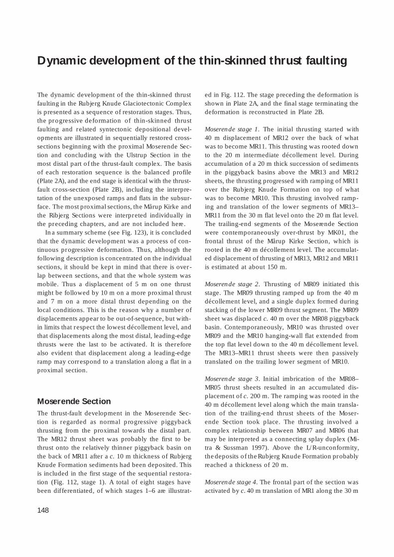
148
Dynamic development of the thin-skinned thrust faulting
The dynamic development of the thin-skinned thrustfaulting in the Rubjerg Knude Glaciotectonic Complexis presented as a sequence of restoration stages. Thus,the progressive deformation of thin-skinned thrustfaulting and related syntectonic depositional devel-opments are illustrated in sequentially restored cross-sections beginning with the proximal Moserende Sec-tion and concluding with the Ulstrup Section in themost distal part of the thrust-fault complex. The basisof each restoration sequence is the balanced profile(Plate 2A), and the end stage is identical with the thrust-fault cross-section (Plate 2B), including the interpre-tation of the unexposed ramps and flats in the subsur-face. The most proximal sections, the Mårup Kirke andthe Ribjerg Sections were interpreted individually inthe preceding chapters, and are not included here.
In a summary scheme (see Fig. 123), it is concludedthat the dynamic development was a process of con-tinuous progressive deformation. Thus, although thefollowing description is concentrated on the individualsections, it should be kept in mind that there is over-lap between sections, and that the whole system wasmobile. Thus a displacement of 5 m on one thrustmight be followed by 10 m on a more proximal thrustand 7 m on a more distal thrust depending on thelocal conditions. This is the reason why a number ofdisplacements appear to be out-of-sequence, but with-in limits that respect the lowest décollement level, andthat displacements along the most distal, leading-edgethrusts were the last to be activated. It is thereforealso evident that displacement along a leading-edgeramp may correspond to a translation along a flat in aproximal section.
Moserende SectionThe thrust-fault development in the Moserende Sec-tion is regarded as normal progressive piggybackthrusting from the proximal towards the distal part.The MR12 thrust sheet was probably the first to bethrust onto the relatively thinner piggyback basin onthe back of MR11 after a c. 10 m thickness of RubjergKnude Formation sediments had been deposited. Thisis included in the first stage of the sequential restora-tion (Fig. 112, stage 1). A total of eight stages havebeen dif ferentiated, of which stages 1–6 are illustrat-
ed in Fig. 112. The stage preceding the deformation isshown in Plate 2A, and the final stage terminating thedeformation is reconstructed in Plate 2B.
Moserende stage 1. The initial thrusting started with40 m displacement of MR12 over the back of whatwas to become MR11. This thrusting was rooted downto the 20 m intermediate décollement level. Duringaccumulation of a 20 m thick succession of sedimentsin the piggyback basins above the MR13 and MR12sheets, the thrusting progressed with ramping of MR11over the Rubjerg Knude Formation on top of whatwas to become MR10. This thrusting involved ramp-ing and translation of the lower segments of MR13–MR11 from the 30 m flat level onto the 20 m flat level.The trailing-end segments of the Moserende Sectionwere contemporaneously over-thrust by MK01, thefrontal thrust of the Mårup Kirke Section, which isrooted in the 40 m décollement level. The accumulat-ed displacement of thrusting of MR13, MR12 and MR11is estimated at about 150 m.
Moserende stage 2. Thrusting of MR09 initiated thisstage. The MR09 thrusting ramped up from the 40 mdécollement level, and a single duplex formed duringstacking of the lower MR09 thrust segment. The MR09sheet was displaced c. 40 m over the MR08 piggybackbasin. Contemporaneously, MR10 was thrusted overMR09 and the MR10 hanging-wall flat extended fromthe top flat level down to the 40 m décollement level.The MR13–MR11 thrust sheets were then passivelytranslated on the trailing lower segment of MR10.
Moserende stage 3. Initial imbrication of the MR08–MR05 thrust sheets resulted in an accumulated dis-placement of c. 200 m. The ramping was rooted in the40 m décollement level along which the main transla-tion of the trailing-end thrust sheets of the Moser-ende Section took place. The thrusting involved acomplex relationship between MR07 and MR06 thatmay be interpreted as a connecting splay duplex (Mi-tra & Sussman 1997). Above the L/R-unconformity,the deposits of the Rubjerg Knude Formation probablyreached a thickness of 20 m.
Moserende stage 4. The frontal part of the section wasactivated by c. 40 m translation of MR1 along the 30 m

149
décollement level over the lowermost trailing-end seg-ments in the Stortorn Section. MR02 and MR03 fol-lowed this translation, whereas MR04 ramped up onelevel from the 40 m décollement level to the 30 m flatlevel that resulted in the initial ramping of MR04 upover the Rubjerg Knude Formation on the back ofMR03. The continued displacement consequently re-orientated thrust sheets MR05–MR07 into more steep-ly dipping orientations. The trailing-end thrust sheetsfrom MR08 and northwards were translated passivelyduring this displacement.
Moserende stage 5. The frontal displacement of MR01continued along the 20 m flat level over the trailing-end segment of the Stortorn Section. MR02 rampedup along the footwall ramp at the trailing end of MR01during a fault-bend rotation, which also included thelower segment of MR01u. A vertical thrust separationof c. 10 m brought MR02 up along the northern termi-nation of the MR01 piggyback basin. During the pas-sage of two intermediate ramps, an irregular anticlineformed on the back of MR02 that had significant im-plications for the synsedimentary structures formedin the MR02 piggyback basin (see description of theMoserende Section, above).
During MR04 thrusting, MR03 was imbricated alongthe upper 10 m flat level and the MR03b and MR03cthrust segments started to break through the piggy-back basin. From the rear, MR04 was pushed by MR05which had to pass up over the fault-bend-folded seg-ment MR04u. Together with MR06 and MR07, the MR05thrust sheet moved up to the highest level indicatedby the L/R-unconformity, situated c. 20 m above sealevel on the back of MR06 and MR07, and their thrustfaults were steepened into a nearly vertical position.
Moserende stage 6. In the frontal part of the Moser-ende Section, MR01 picked up a lower segment andthrust up to the 20 m flat level, which consequentlyalso elevated the piggyback basin up into its presenthigh level. The trailing-end ramp of MR01 formed thefootwall ramp for the MR02 thrusting, which resultedin a fault bend of MR02 as well as MR03. This wasfollowed by the final displacement of 18 m along theleading MR03 thrust. Minor adjustments and re-orien-tation of MR04–MR07 followed the ramping of MR03,and the trailing-end thrust sheets MR08–MR13 werepassively displaced by translation along the 40 m dé-collement level.Moserende stage 7. During this stage, a complex du-plex was formed by thrusting of the frontal lower seg-
ments, which also including the trailing-end segmentsof the Stortorn Section.
Moserende stage 8. The final displacement along theleading thrust-fault ramp in the Moserende Sectionprogressed up along the Stortorn trailing-end foot-wall ramp. Moreover, the fault-bend folding due tothrusting in the Stortorn Section brought the thrustsheets into their present steeply dipping orientation.
Moserende Section: summary dataBalanced length (L0): 1120 mCross-section length (L1): 650 mShortening (ΔL): 470 mCompression: 40.2%
Stortorn SectionThe most important development in the Stortorn Sec-tion was the change from the lowermost 40 m décol-lement level to the 30 m décollement level. The ramp,or progressive development of lower ramps, whichmarked the change, is here referred to as the Stortornlower segment footwall ramp, and was located some-where near the thrust between ST04 and ST03. Thus,the ST03–ST01 thrust sheets had their lower décolle-ment level at 30 m, whereas the thrust faults relatedto ST04–ST10 were rooted in the 40 m décollementlevel.
Formation of a duplex complex comprising the low-ermost thrust segments exposed the Stortorn Forma-tion, the oldest strata involved in the thrusting. In thefrontal part of the section, a complex stacking of low-er segments, remaining in the subsurface from dis-placement in the Grønne Rende Section, resulted induplex formation that elevated ST01–ST03 about 30 mabove the reference level. Due to arguments present-ed later (see Grønne Rende Section) the duplex stack-ing had to have been contemporaneous with the short-ening of the Grønne Rende Section. In the StortornSection, seven stages have been differentiated of whichstages 1–5 are illustrated in Fig. 113.
Stortorn stage 1. This stage is a direct continuation ofthe displacement in Moserende stage 4. In the Stor-torn Section, deformation was initiated by imbrica-tion of ST07, ST09 and ST10 with an accumulated dis-placement of about 50 m. This resulted in a ramping
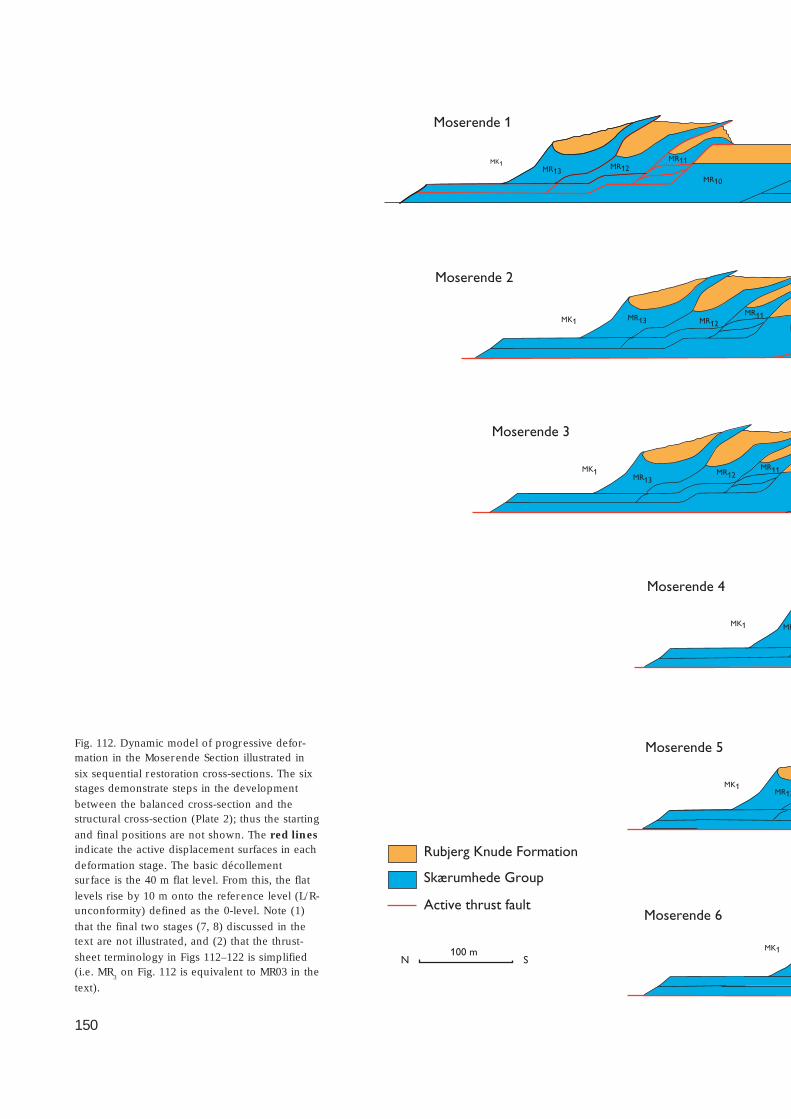
150
Skærumhede Group
Active thrust fault
Rubjerg Knude Formation
Moserende 2
MR13 MR12MR11
MMK1
Moserende 3
MK1MR13
MR12MR11
Moserende 4
MK1 MR
Moserende 5
MK1MR13
Moserende 6
MK1100 mN S
Moserende 1
MR13MR12
MR11
MR10
MK1
Fig. 112. Dynamic model of progressive defor-mation in the Moserende Section illustrated in
six sequential restoration cross-sections. The sixstages demonstrate steps in the development
between the balanced cross-section and thestructural cross-section (Plate 2); thus the starting
and final positions are not shown. The red linesindicate the active displacement surfaces in each
deformation stage. The basic décollementsur face is the 40 m flat level. From this, the flat
levels rise by 10 m onto the reference level (L/R-unconformity) defined as the 0-level. Note (1)
that the final two stages (7, 8) discussed in thetext are not illustrated, and (2) that the thrust-
sheet terminology in Figs 112–122 is simplified(i.e. MR
3 on Fig. 112 is equivalent to MR03 in the
text).
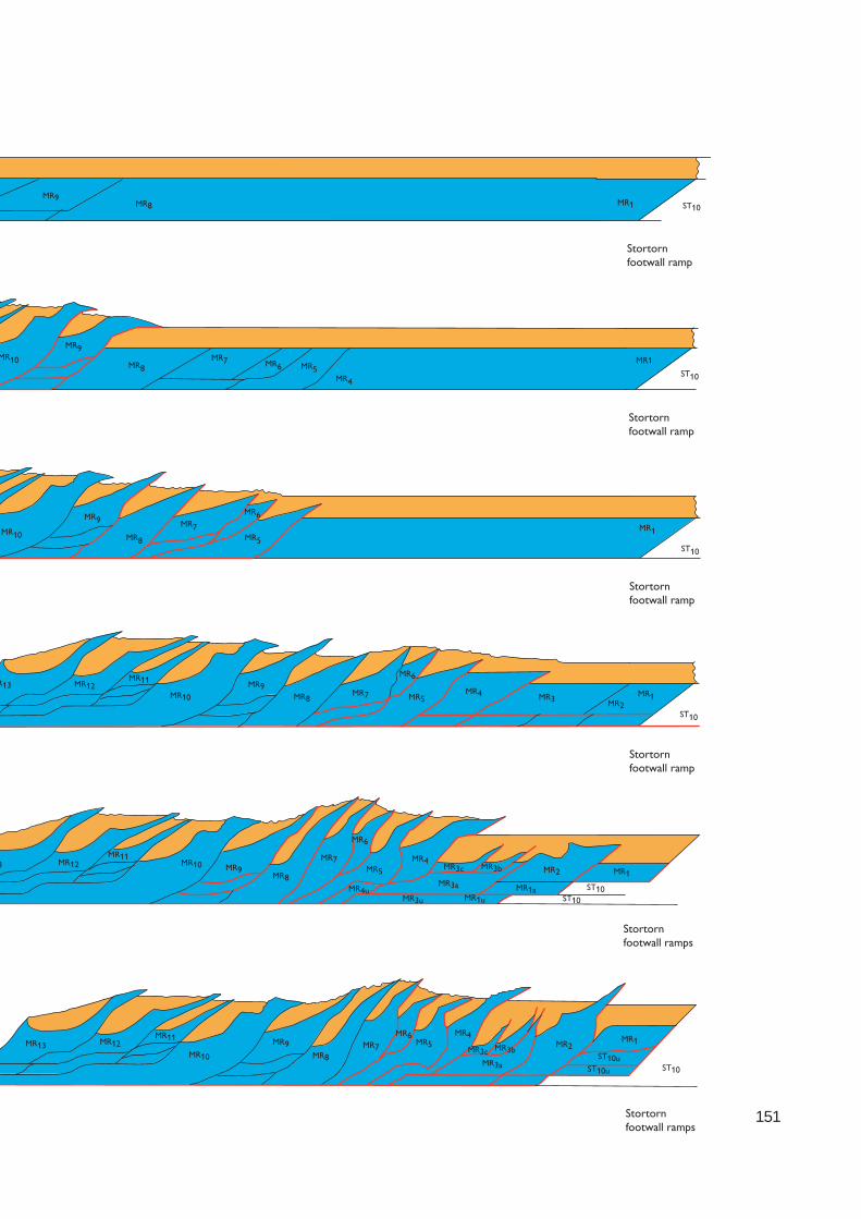
151
Stortornfootwall ramp
Stortornfootwall ramp
Stortornfootwall ramp
MR10
MR9
MR8MR7 MR6 MR5
MR4
MR1
ST10
MR10
MR9
MR8
MR7
MR6
MR5
MR1
ST10
MR1
ST10
R13 MR12MR11
MR10
MR9MR8
MR7
MR6
MR5MR4 MR3 MR2
Stortornfootwall ramps
3 MR12MR11
MR10 MR9MR8
MR7
MR6
MR5
MR4
MR4uMR3a
MR3u
MR3c MR3b MR2
MR1aMR1u
MR1
ST10ST10
Stortornfootwall ramps
MR13 MR12MR11
MR10MR7
MR6MR5
MR4
MR3c MR3b
MR3a
MR2MR1
ST10
ST10uST10u
MR8
MR9
Stortornfootwall ramp
MR9MR8 ST10
MR1

152
100 mN S
Skærumhede Group
Active thrust fault
Rubjerg Knude Formation
MR1
ST10 ST9ST8 ST7
ST6
Stortorn 2
ST5
MR1
MR1 ST10u
ST10 ST9 ST8 ST7 ST6
ST5uST8uST8uST9u
Stortorn 1
Stortorn footwall ramp
ST10MR1
ST9
ST6
ST7
ST8
Stortorn 4
Stortorn footwall ramps
Stortorn 5
Stortorn footwall ramps
ST10
MR1ST10
ST9 ST8
Stortorn 3
Stortorn footwall ramps
Fig. 113. Dynamic model of progressive
deformation in the Stortorn Section illustratedin five sequential restoration cross-sections.
The cross-sections demonstrate steps in thedevelopment between the balanced cross-
section and the structural cross-section (Plate2); thus the starting and final positions are not
shown. The red lines indicate the activedisplacement sur faces in each deformation
stage. Note that the duplex segments GRu refer
to elements that had to be deformed contem-
poraneously with the shortening taking placein the Grønne Rende Section; duplex seg-
ments STs refer to horse/splint segments. The
final two stages (6, 7) discussed in the text are
not illustrated.

153
ST4RF6
ST1s
ST1ST2ST3
ST4 ST4s
ST4s
ST4s
ST4s
ST2sST1s
Stortorn lower ramp Rubjerg Knude Fyr rampfrontal footwall ramp
ST5
ST5ST4
ST2ST3
Rubjerg Knude Fyr footwall ramp
Rubjerg Knude Fyr footwall ramp
Stortorn lower segment footwall ramps
Rubjerg Knude Fyrfootwall ramp
Stortorn lower segment footwall ramps
ST9
ST7
ST6
ST5
ST4
ST3 ST2 ST1
RF6GRuGRu
GRu
ST8
ST6
ST5ST4
ST3 ST2 ST1
ST2s RF6
Stortorn lower footwall ramp
RF6ST1s
ST1
ST1s RF6
154
up of ST10 from décollement level 40 m to flat level30 m, along which the translation displacement tookplace. Most of the ST09 thrust sheet was also rampedup by the formation of a lower duplex structure. BothST10 and ST09 were affected by fault-bend folding,which created a major distortion of the L/R-unconform-ity surface in the uppermost part of the thrust sheets.
Stortorn stage 2. During an accumulated displacementof about 200 m related to the ST10 and ST09 thrusts,ramping progressed with development of the firstimbrications of ST08 and ST06. Due to ramping fromthe lowest décollement level to the 30 m flat level inthe trailing end of ST06, a fault bend affected the ST07–ST10 thrust sheets that were translated piggyback onthe ST06 thrust sheet. This contributed to the steep-ening up of the ST07–ST10 thrust structures.
In the frontal part of the section, the imbricate thrust-ing was initiated at ST01–ST03. Accumulation of sedi-ments referred to the Rubjerg Knude Formationreached a maximum thickness of about 20 m, notablyin the synformal troughs of ST03 and ST09 that formedduring the progress over the ramps below.
Stortorn stage 3. At this stage, ST05 was thrust about40 m up over the footwall ramp on the back of ST04.The ST05 thrust was rooted in the 30 m flat level, andduring a passage of a lower ramp from flat level 30 mto 20 m, the initial fault-bend-fold resulted in undula-tion of the L/R-unconformity at the top of the ST05thrust sheet. The ST06 thrust sheet progressed overthe footwall flat of ST05, and both thrust faults wererooted down to the 30 m flat level along which themain translation of the sheets emplaced piggybackon ST06 took place. The ST08 thrust sheet was finallydisplaced along the upper flat at the top of the ST07piggyback basin. Consequently, most of the 20 m thicksuccession in this piggyback basin was preserved andindicates the maximum level of sediment accumula-tion in the Rubjerg Knude Formation during stage 3.Thrusting of the ST08 sheet along the footwall rampon the back of ST07 resulted in a further steepening ofST09 and ST10, while the frontal elevated parts of theST08–ST09 thrust sheets became subject to erosion.
The trailing-end lower segments of ST10–ST07 wereover-thrust by the frontal parts of MR01 and MR02,corresponding to stage 7 in the Moserende Section.The accumulated displacement in Stortorn stage 3 wasof the order of 320 m.
Stortorn stage 4. During this stage, the ST04 thrust
sheet was thrust 40 m over the piggyback basin ofST03, and ST05 was thrust about 70 m over the upperflat on top of the piggyback basin of ST04. Duringthis relatively large displacement of ST05, two lowerduplex segments were picked up from the lower 40m décollement level. After ramping over the Stortornlower ramp, the duplex segments participated in thethrusting up along the footwall ramp on the back ofST04.
The lower trailing-end segments of the StortornSection were finally thrust up along the steep foot-wall ramp on the back of ST10 and subsequently thefrontal parts of the Moserende Section were broughtinto their present upright orientation. Erosion and re-deposition affected the piggyback basins on ST05 andST08, whereas thrusting over ST07 and ST04 sealedthese piggyback basins. The accumulated displace-ment reached about 410 m.
Stortorn stage 5. A substantial displacement, in theorder of 80 m, took place along the leading thrust inthe Stortorn Section at this relatively late stage of de-velopment of the structures at Stortorn. However, thisis only a small amount of the accumulated displace-ment (c. 500 m) which is of the same order of magni-tude as that taken up by the duplex stacking of thelower trailing-end segments of the Rubjerg Knude Fyrand Grønne Rende Sections. The ramping and thrust-ing of ST01–ST04 over this duplex structure explainsthe high elevation of the L/R-unconformity and over-lying piggyback basins in the frontal part of the Stor-torn Section. The formation of the duplex stack com-prising the lower duplex segments annotated GRu inFig. 113 would have taken place only after the imbri-cate thrusting in the Grønne Rende Section developed(see below). The combination of displacement at theleading edge in one section and stacking of lowerduplex segments in another, indicates a continuousprogressive thrust-fault evolution.
During the propagation of ST05, the trailing end ofST04 was involved in a duplex formation that result-ed in fault-bend folding of the earlier formed ST05lower duplex at the Stortorn lower ramp. The piggy-back basin on the back of the ST05 thrust sheet wasdeformed into a north-verging syncline due to steep-ening. A similar re-orientation is seen in the thrust-isolated piggyback basins in ST10 and ST09.
A marked diapirism and remobilisation of mud inthe ST01–ST03, ST05–ST07 and ST09 thrust sheets sug-gests that the diapirism was related to the intensity oframping, especially when the ramping involved the

155
Fig. 114. Dynamic model of progressive deformation in the Rubjerg Knude Fyr Section illustrated in four sequential restorationcross-sections. The cross-sections demonstrate five stages in the development between the balanced cross-section and the structural
cross-section (Plate 2). The red lines indicate the active displacement surfaces in each deformation stage. Note that the tip of theRF04 thrust sheet was displaced by normal faulting during syntectonic deposition in the RF03/RF04 piggyback basin.
lower level segments and fault-bend folding of thesesegments.
Stortorn stage 6. The final ramping of lower segmentsfrom décollement level 40 m to flat level 30 m at thebase of ST05 terminated the translation along the low-ermost 40 m décollement level. For the sections fur-
ther south, the lower décollement level was situatedat the 30 m level. In the frontal part of the section,continued minor compression steepened the thruststructures, and the tips of ST02 and ST03 were erodedand deposited in the piggyback basin of ST01.
Stortorn stage 7. The structural complex, including the

156
ST01 thrust sheet and the underlying duplex struc-ture, became fault-bend-folded during the thrust prop-agation related to the progressive deformation in theRubjerg Knude Fyr Section.
Stortorn Section: summary dataBalanced length (L0): 1125 mCross-section length (L1): 570 mShortening (ΔL): 555 mCompression: 49.3%
Rubjerg Knude Fyr SectionThe Rubjerg Knude Fyr Section roots into the 30 mdécollement level. The most striking features devel-oped in the Rubjerg Knude Fyr Section are the largeolistoliths in the piggyback basin that were derivedfrom the collapse and gravity gliding of a projectingsegment of ST04. Five stages in dynamic developmenthave been distinguished, which are illustrated by fourcross-sections in Fig. 114.
Rubjerg Knude Fyr stage 1. During sedimentation ofthe first 10 m of sand of the Rubjerg Knude Forma-tion, the RF05, RF04 and RF03 thrust sheets were thrustup along their footwall ramps. RF04 was displaced 90m along the upper flat level (10 m level) before thefrontal part propagated up along the upper ramp. Witha displacement of about 30 m, this brought the noseof the RF04 thrust sheet up into the open air, abovethe sedimentation level of the Rubjerg Knude Forma-tion. The displacement on the other two thrusts amount-ed to c. 20 m, implying an accumulated displacementof 70 m.
Rubjerg Knude Fyr stage 2. The exposed nose of theRF04 thrust sheet slumped down along a normal faultinto the piggyback basin of RF03. At the same time,the frontal nose of RF03 was eroded away and sedi-mentation of the Rubjerg Knude Formation onlappedand covered these features. At the leading edge ofthe section, thrusting was initiated that brought RF01and RF02 up over what was to become the trailing-end segments of the Grønne Rende Section.
Rubjerg Knude Fyr stage 3. The frontal imbrication ofRF01 and RF02 progressed during sedimentation upto about 20 m above the main L/R-unconformity lev-
el. The RF05–RF06 thrust sheet ramped up onto theintermediate flat above the trailing-end segment ofRF04. The RF04 thrust sheet was displaced about 70m up along the relatively steep footwall ramp at thetrailing end of RF03. Due to the fault-bend folding ofRF04, the RF05–RF06 hanging-wall ramp was rotatedinto a vertical position.
Rubjerg Knude Fyr stage 4. When the second ‘drop’ ofthe frontal part of thrust sheet RF04 took place, a c. 45m long slab of the relatively thin thrust-sheet noseslumped down along a normal fault with a verticalseparation of more than 10 m. The ‘drops’ may beregarded as two break-back sequences of the RF04thrust sheet (in the terminology used by Mitra & Suss-man 1997; see Figs 99, 100). Sediment accumulationcontinued in the piggyback basin to a thickness ofmore than 30 m, including the ‘dropped’ noses of RF04.The final accumulation in the piggyback basin tookplace while the displacement in the Rubjerg KnudeFyr Section was concluded more than 500 m laterallyto the south. The translation progressed along the 20m flat level on top of what was to become the lowertrailing-end segments of the Grønne Rende Section.
Rubjerg Knude Fyr stage 5. The continued displace-ment of RF04 resulted in structural propagation of thissheet above its own piggyback basin with the‘dropped’ thrust noses. Stage 5 in the Rubjerg KnudeFyr Section is interpreted to have been contempora-neous with stage 7 in the Stortorn Section in whichcompression brought the thrust sheets into their final,steeply inclined position.
Rubjerg Knude Fyr Section: summary dataBalanced length (L
0): 525 m
Cross-section length (L1): 260 m
Shortening (ΔL): 265 mCompression: 50.5%
Grønne Rende SectionThe impressive imbricate fan composed of 12 uprightthin thrust sheets is the essential element in the GrønneRende Section. As a consequence of the displacementin the imbricate fan, 550 m of trailing-end lower seg-ments were left behind to be stacked in a duplex be-low the frontal part of the Stortorn Section (Fig. 113).
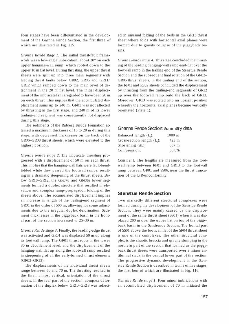
157
Four stages have been differentiated in the develop-ment of the Grønne Rende Section, the first three ofwhich are illustrated in Fig. 115.
Grønne Rende stage 1. The initial thrust-fault frame-work was a low-angle imbrication, about 20° on eachupper hanging-wall ramp, which rooted down to theupper 10 m flat level. During thrusting, the upper thrustsheets were split up into three main segments withleading thrust faults below GR02, GR06 and GR11/GR12 which ramped down to the main level of de-tachment in the 20 m flat level. The initial displace-ment of the imbricate fan is regarded to have been 20 mon each thrust. This implies that the accumulated dis-placement sums up to 240 m. GR01 was not affectedby thrusting in the first stage, and 240 m of its lowertrailing-end segment was consequently not displacedduring this stage.
The sediments of the Rubjerg Knude Formation at-tained a maximum thickness of 15 to 20 m during thisstage, with decreased thicknesses on the back of theGR06–GR08 thrust sheets, which were elevated to thehighest position.
Grønne Rende stage 2. The imbricate thrusting pro-gressed with a displacement of 50 m on each thrust.This implies that the hanging-wall flats were fault-bend-folded while they passed the footwall ramps, result-ing in a dramatic steepening of the thrust sheets. Be-low GR10–GR12, the GR07u and GR08u lower seg-ments formed a duplex structure that resulted in ele-vation and complex ramp-propagation folding of thesheets above. The accumulated displacement impliesan increase in length of the trailing-end segment ofGR01 in the order of 500 m, allowing for some adjust-ments due to the irregular duplex deformation. Sedi-ment thicknesses in the piggyback basin in the front-al part of the section increased to 25–30 m.
Grønne Rende stage 3. Finally, the leading-edge thrustwas activated and GR01 was displaced 50 m up alongits footwall ramp. The GR01 thrust roots in the lower30 m décollement level, and the displacement of thehanging-wall flat up along the footwall ramp resultedin steepening of all the early-formed thrust elements(GR02–GR13).
The displacements of the individual thrust sheetsrange between 60 and 70 m. The thrusting resulted inthe final, almost vertical, orientation of the thrustsheets. In the rear part of the section, complex defor-mation of the duplex below GR10–GR13 was reflect-
ed in unusual folding of the beds in the GR13 thrustsheet where folds with horizontal axial planes wereformed due to gravity collapse of the piggyback ba-sins.
Grønne Rende stage 4. This stage concluded the thrust-ing of the leading hanging-wall ramp-and-flat over thefootwall ramp in the trailing end of the Stenstue RendeSection and the subsequent final rotation of the GR02–GR05 thrust sheets. In the trailing end of the section,the RF01 and RF02 sheets concluded the displacementby thrusting from the trailing-end segments of GR12up over the footwall ramp onto the back of GR13.Moreover, GR13 was rotated into an upright positionwhereby the horizontal axial planes became verticallyorientated (Plate 1).
Grønne Rende Section: summary dataBalanced length (L0): 1080 mCross-section length (L1): 423 mShortening (ΔL): 657 mCompression: 60.8%
Comment. The lengths are measured from the foot-wall ramp between RF01 and GR13 to the footwallramp between GR01 and SS06, near the thrust trunca-tion of the L/R-unconformity.
Stenstue Rende SectionTwo markedly different structural complexes wereformed during the development of the Stenstue RendeSection. They were mainly caused by the displace-ment of the same thrust sheet (SS01) when it was dis-placed 200 m over the upper flat on top of the piggy-back basin in the Sandrende Section. The frontal partof SS01 above the footwall flat of the SR04 thrust sheetis one of the complexes. The other structural com-plex is the chaotic breccia and gravity slumping in thenorthern part of the section that formed as the piggy-back thrust sheets were transported over a minor an-tiformal stack in the central lower part of the section.The progressive dynamic development in the Sten-stue Rende Section is described in terms of five stages,the first four of which are illustrated in Fig. 116.
Stenstue Rende stage 1. Four minor imbrications withan accumulated displacement of 70 m initiated the
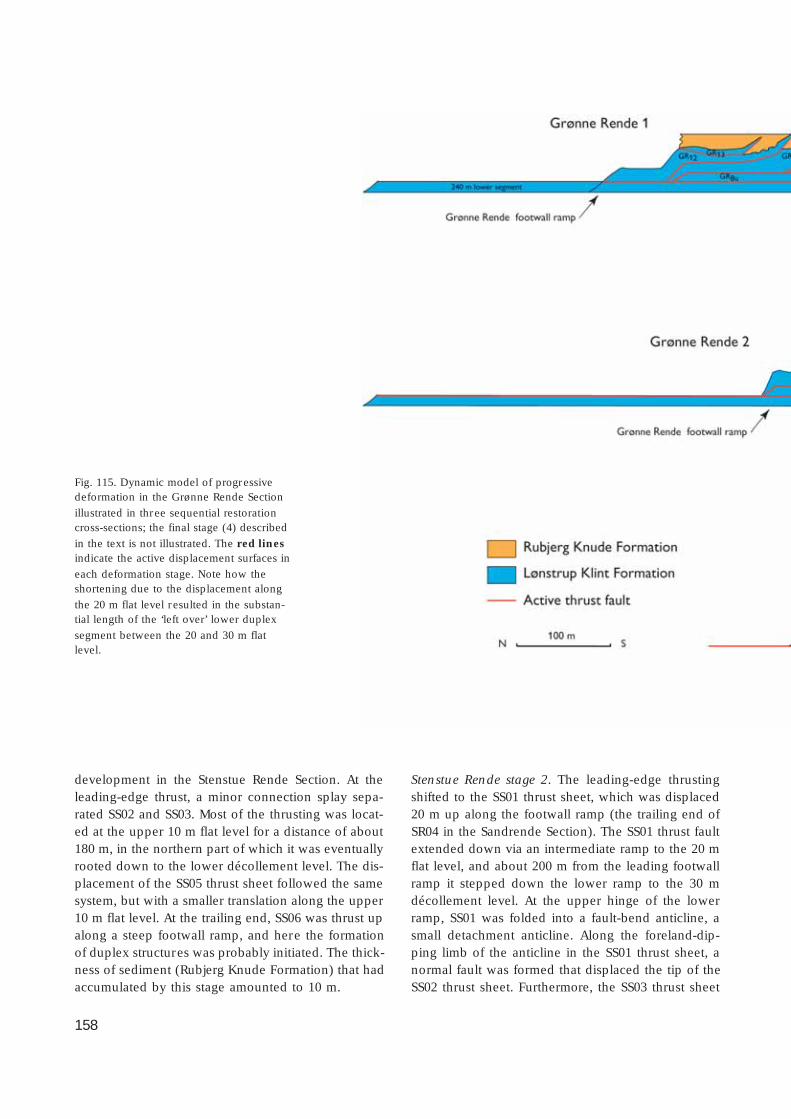
158
development in the Stenstue Rende Section. At theleading-edge thrust, a minor connection splay sepa-rated SS02 and SS03. Most of the thrusting was locat-ed at the upper 10 m flat level for a distance of about180 m, in the northern part of which it was eventuallyrooted down to the lower décollement level. The dis-placement of the SS05 thrust sheet followed the samesystem, but with a smaller translation along the upper10 m flat level. At the trailing end, SS06 was thrust upalong a steep footwall ramp, and here the formationof duplex structures was probably initiated. The thick-ness of sediment (Rubjerg Knude Formation) that hadaccumulated by this stage amounted to 10 m.
Stenstue Rende stage 2. The leading-edge thrustingshifted to the SS01 thrust sheet, which was displaced20 m up along the footwall ramp (the trailing end ofSR04 in the Sandrende Section). The SS01 thrust faultextended down via an intermediate ramp to the 20 mflat level, and about 200 m from the leading footwallramp it stepped down the lower ramp to the 30 mdécollement level. At the upper hinge of the lowerramp, SS01 was folded into a fault-bend anticline, asmall detachment anticline. Along the foreland-dip-ping limb of the anticline in the SS01 thrust sheet, anormal fault was formed that displaced the tip of theSS02 thrust sheet. Furthermore, the SS03 thrust sheet
Fig. 115. Dynamic model of progressivedeformation in the Grønne Rende Section
illustrated in three sequential restorationcross-sections; the final stage (4) described
in the text is not illustrated. The red linesindicate the active displacement surfaces in
each deformation stage. Note how theshortening due to the displacement along
the 20 m flat level resulted in the substan-tial length of the ‘left over’ lower duplex
segment between the 20 and 30 m flatlevel.
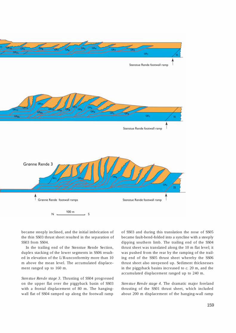
159
became steeply inclined, and the initial imbrication ofthe thin SS03 thrust sheet resulted in the separation ofSS03 from SS04.
In the trailing end of the Stenstue Rende Section,duplex stacking of the lower segments in SS06 result-ed in elevation of the L/R-unconformity more than 10m above the mean level. The accumulated displace-ment ranged up to 160 m.
Stenstue Rende stage 3. Thrusting of SS04 progressedon the upper flat over the piggyback basin of SS03with a frontal displacement of 80 m. The hanging-wall flat of SS04 ramped up along the footwall ramp
of SS03 and during this translation the nose of SS05became fault-bend-folded into a syncline with a steeplydipping southern limb. The trailing end of the SS04thrust sheet was translated along the 10 m flat level; itwas pushed from the rear by the ramping of the trail-ing end of the SS05 thrust sheet whereby the SS06thrust sheet also steepened up. Sediment thicknessesin the piggyback basins increased to c. 20 m, and theaccumulated displacement ranged up to 240 m.
Stenstue Rende stage 4. The dramatic major forelandthrusting of the SS01 thrust sheet, which includedabout 200 m displacement of the hanging-wall ramp
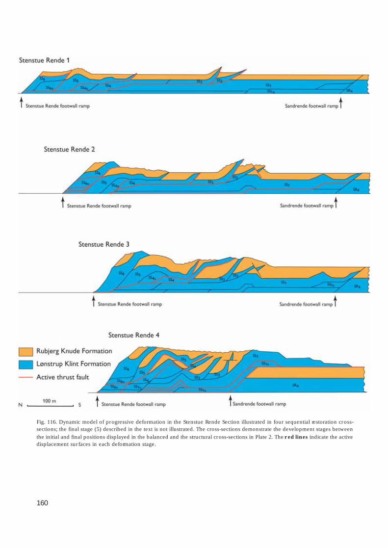
160
Fig. 116. Dynamic model of progressive deformation in the Stenstue Rende Section illustrated in four sequential restoration cross-sections; the final stage (5) described in the text is not illustrated. The cross-sections demonstrate the development stages between
the initial and final positions displayed in the balanced and the structural cross-sections in Plate 2. The red lines indicate the activedisplacement sur faces in each deformation stage.

161
over the piggyback basin of the Sandrende Section,occurred contemporaneously with the formation ofan antiformal stack above the trailing end of SS01. Thecreation of the antiformal stack had already been initia-ted by the earlier formation of the minor detachmentanticline at the ramp splitting the lower segments ofSS01 (the SS01u segments). A duplex duplication ofthe lower SS01u segments accentuated the anticline,and finally the SS03 thrust sheet riding piggyback onSS01 was folded into an anticline with a steep fore-land-dipping southern limb (Fig. 90). Along this limb,a normal fault developed that displaced the frontalpart of the SS04 thrust sheet. A chaotic soft sedimen-tary fault breccia was formed during the stretchingand fault separation of SS04 (Fig. 91). Due to an extrapush from the rear, the SS05 thrust sheet was displaceda further 30 m to the south, which resulted in theformation of a huge southerly overturned slump foldabove the normal fault zone (Fig. 89).
The accumulated displacement totals about 470 m.The displacement of the SS01 hanging-wall flat upalong the steeply dipping footwall ramp constrainsthe sequential thrusting of the Stenstue Rende rela-tive to the Sandrende thrusting. Thus stage 4 couldnot have begun before the maximum sedimentationin the piggyback basin was accomplished in the Sand-rende Section. The initial SS01 thrusting could be re-garded as a growth fault, whereby the syntectonicaccumulation of sand added to the steepening of thefootwall ramp. The present vertical to northerly over-turned orientation of the SS01 hanging-wall flat andramp resulted from differential thrusting and fault-bendof the SS01u lower hanging-wall ramp. Note also there-orientation of the normal fault at the tip of SS02,which due to the same deformation was bent into ahorizontal position.
Stenstue Rende stage 5. This stage corresponds to stage6 in the Sandrende Section, wherein the SS01 thrustsheet riding piggyback on SR04 was displaced bynormal faulting (Fig. 117, stage 6).
Stenstue Rende Section: summary dataBalanced length (L
0): 760 m
Cross-section length (L1): 285 m
Shortening (ΔL): 485 mCompression: 62.5%
Comment. The lengths are measured from the foot-
wall ramp between GR01 and SS06 to the footwallramp between SS01 and SR04. If the compression wascalculated from the leading-edge thrust tip of SS01 tothe trailing-end footwall ramp of SS06, L1 amounts to455 m, ΔL = 305 m and the calculated compressionwould only be 40.1%.
Sandrende SectionThe dynamic development of the Sandrende Sectionwas formerly interpreted as a combination of diapir-ism and normal faulting caused by volume exchangeduring thrust propagation (Sadolin et al.1997). Themodel presented here aims at an explanation of thedevelopment purely based on a thin-skinned thrust-fault model including dif ferential ramping and duplexformation. Thus, the diapirism is interpreted to be aneffect of ramping and fault-bend folding growth, sim-ilar to the model of Mitra & Sussman (1997), but alsoincluding mud-mobilisation and exaggeration of back-limb thrusting. The normal faulting occurring in theSandrende Section is interpreted as the effect of dif-ferential ramping of a lower trailing-end segment thatcreated foreland-dipping features above a hanging-wall ramp propagation along an intermediate foot-wall flat. Six stages of dynamic development have beendif ferentiated in the Sandrende Section (Fig. 117).
Sandrende stage 1. After initial deposition of a 3–5 mthick succession of Rubjerg Knude Formation sedi-ments, the SR04 thrust sheet started thrusting about50 m over the upper flat. The dip of the footwall rampwas relatively gentle, only c. 14°, and in the 15 m flatlevel the thrust fault may be traced along a minor flatsegment on top of the lower trailing-end segment ofSR03 (SR03u). From the minor intermediate flat, thethrust fault rooted down to the 30 m décollement lev-el along a 20° dipping footwall ramp of SR03u. Notethat an upper and lower SR04 hanging-wall ramp wasintroduced subsequently.
Sandrende stage 2. Translation of the lower SR04 hang-ing-wall ramp along the intermediate flat establishedthe anticline in the central part of the SR04 thrust sheet.The SR03 thrust sheet started to propagate towards itsforeland along the upper 10 m hanging-wall flat, andthe frontal part of SR03 was displaced 50 m over theupper flat on top of the piggyback basin of SR02. Thetip of the SR02 thrust sheet propagated up along agrowth-fault ramp, which caused the steeply dipping
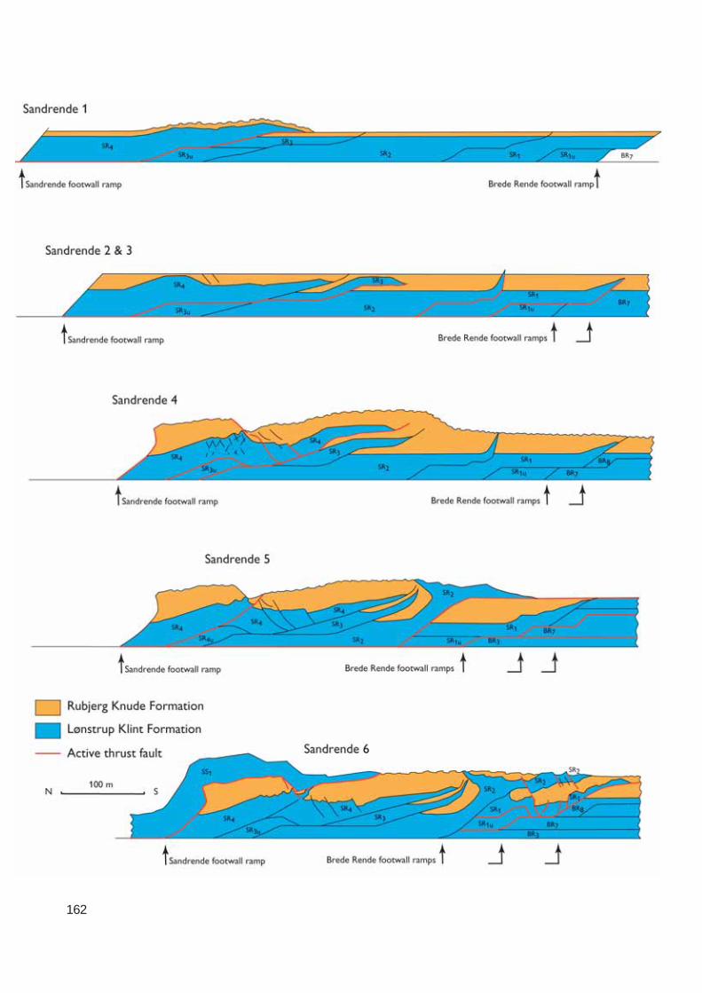
162

163
orientation of the northern boundary of the piggy-back basin at the top of the SR01 thrust sheet. The accu-mulated displacement ranged up to about 150 m, in-cluding the initial thrusting of SR01.
Sandrende stage 3. During stage 3, the thickness ofthe sediments of the Rubjerg Knude Formation reached20 m in the piggyback basins in the Sandrende Sec-tion. In the basin at the top of the SR04 thrust sheet,the thickness varied considerably. The reason for thisvariation is that the top of the anticline above theSR04 lower hanging-wall ramp was subjected to ero-sion while deposition continued in the frontal part,south of the anticline, as well as in the basin north ofthe anticline. On the foreland-dipping flank of theanticline, minor sets of normal growth faults governedsedimentation (Fig. 87). The tip of the SR04 thrustsheet suffered minor erosion before deposition re-sumed during thrust propagation. This is document-ed by the angular onlap relationships described bySadolin et al. (1997).
Sandrende stage 4. The thrusting of SR04 continuedwith 50 m further displacement. Below the trailingend of the SR04 thrust sheet, the SR03u lower seg-ment was picked up and displaced onto the footwallramp of SR02. This minor duplex and ramp thrustingaccentuated the SR04 hanging-wall anticline, and nor-mal faulting on the foreland-dipping limb progressed.Above the crest of the SR03u detachment anticline, asignificant normal fault complex developed. Here inthe SR04 thrust sheet, a dense network of conjugatenormal faults (Fig. 85) resulted from lateral extensiondue to flexural slip bend over the upper hinge of thelower footwall ramp.
Sandrende stage 5. The thrusting of SR01 propagatedup along the lower and intermediate footwall ramp ofthe trailing segments of the Brede Rende Section. Dur-
ing this ramping, the hanging-wall flat of SR02 pro-gressed up over the piggyback basin of SR01. The tipsof the SR03 and SR04 thrust sheets thus experiencedfault bending up along the footwall flat of SR02. Theatypical northerly overturned tip at the top of the SR02sheet probably formed due to accentuated reverse fault-ing along a former established back-thrust. In the trail-ing part of the section, a minor satellite splay thrust de-veloped, which broke through the SR04 thrust sheetfrom the hanging-wall flat to the footwall flat below SS01.
Sandrende stage 6. The final development of the Sand-rende Section was dominated by complex duplex for-mation and fault-bend folding of the SR01 thrust sheetbelow the frontal part of SR02. During the thrust pro-pagation over the footwall ramp of the trailing-endsegments of the Brede Rende Section, a fault-bend-folded syncline was formed in SR01, which resultedin normal fault displacement of the SR01 piggybackbasin and the overlying frontal part of the SR02 thrustsheet. Similar normal faulting affected the SS01 thrustsheet, which had over-thrust the piggyback basin onthe back of SR04. Due to the intense ramping andfolding of SR01 and its underlying duplex (SR01u) intoan antiformal stack, mud of the Lønstrup Klint Forma-tion was remobilised in SR01, which intruded throughthe hanging-wall flat of SR02 to form the diapir in theSandrende Section.
Sandrende Section: summary dataBalanced length (L
0): 775 m
Cross-section length (L1): 440 m
Shortening (ΔL): 335 mCompression: 43.2%
Comment. The lengths are measured from the foot-wall ramp between SS01 and SR04 to the footwall rampbetween SR01 and BR08, at the level where the rampscut the L/R-unconformity. The volume lost in diapir-ism has not been considered, and a reduced amountof compression would result by measuring L
1 from
the tip of the SR01 thrust sheet to the SR04 footwallramp.
Brede Rende SectionThe development of normal faults associated withforeland-dipping features of hanging-wall ramps trans-
Facing page:
Fig. 117. Dynamic model of progressive deformation in theSandrende Section illustrated by five restoration cross-
sections. Note that stages 2 and 3 include syntectonicsedimentation of the Rubjerg Knude Formation, mainly
related to stage 2, and the thrust-fault configuration conclud-ing stage 3. The cross-sections demonstrate the development
stages between the initial and final positions displayed in thebalanced and the structural cross-sections in Plate 2. The red
lines indicate the active displacement surfaces in eachdeformation stage.
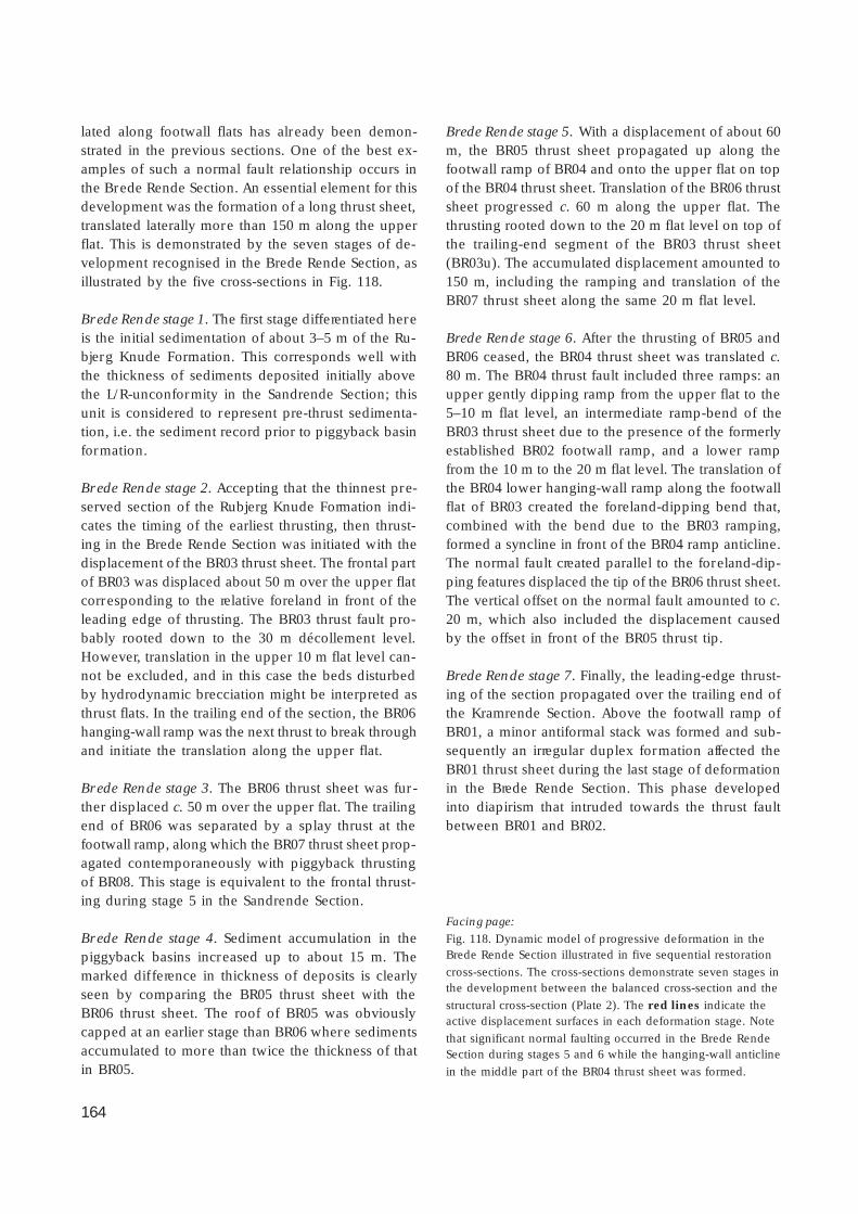
164
lated along footwall flats has already been demon-strated in the previous sections. One of the best ex-amples of such a normal fault relationship occurs inthe Brede Rende Section. An essential element for thisdevelopment was the formation of a long thrust sheet,translated laterally more than 150 m along the upperflat. This is demonstrated by the seven stages of de-velopment recognised in the Brede Rende Section, asillustrated by the five cross-sections in Fig. 118.
Brede Rende stage 1. The first stage differentiated hereis the initial sedimentation of about 3–5 m of the Ru-bjerg Knude Formation. This corresponds well withthe thickness of sediments deposited initially abovethe L/R-unconformity in the Sandrende Section; thisunit is considered to represent pre-thrust sedimenta-tion, i.e. the sediment record prior to piggyback basinformation.
Brede Rende stage 2. Accepting that the thinnest pre-served section of the Rubjerg Knude Formation indi-cates the timing of the earliest thrusting, then thrust-ing in the Brede Rende Section was initiated with thedisplacement of the BR03 thrust sheet. The frontal partof BR03 was displaced about 50 m over the upper flatcorresponding to the relative foreland in front of theleading edge of thrusting. The BR03 thrust fault pro-bably rooted down to the 30 m décollement level.However, translation in the upper 10 m flat level can-not be excluded, and in this case the beds disturbedby hydrodynamic brecciation might be interpreted asthrust flats. In the trailing end of the section, the BR06hanging-wall ramp was the next thrust to break throughand initiate the translation along the upper flat.
Brede Rende stage 3. The BR06 thrust sheet was fur-ther displaced c. 50 m over the upper flat. The trailingend of BR06 was separated by a splay thrust at thefootwall ramp, along which the BR07 thrust sheet prop-agated contemporaneously with piggyback thrustingof BR08. This stage is equivalent to the frontal thrust-ing during stage 5 in the Sandrende Section.
Brede Rende stage 4. Sediment accumulation in thepiggyback basins increased up to about 15 m. Themarked dif ference in thickness of deposits is clearlyseen by comparing the BR05 thrust sheet with theBR06 thrust sheet. The roof of BR05 was obviouslycapped at an earlier stage than BR06 where sedimentsaccumulated to more than twice the thickness of thatin BR05.
Brede Rende stage 5. With a displacement of about 60m, the BR05 thrust sheet propagated up along thefootwall ramp of BR04 and onto the upper flat on topof the BR04 thrust sheet. Translation of the BR06 thrustsheet progressed c. 60 m along the upper flat. Thethrusting rooted down to the 20 m flat level on top ofthe trailing-end segment of the BR03 thrust sheet(BR03u). The accumulated displacement amounted to150 m, including the ramping and translation of theBR07 thrust sheet along the same 20 m flat level.
Brede Rende stage 6. After the thrusting of BR05 andBR06 ceased, the BR04 thrust sheet was translated c.80 m. The BR04 thrust fault included three ramps: anupper gently dipping ramp from the upper flat to the5–10 m flat level, an intermediate ramp-bend of theBR03 thrust sheet due to the presence of the formerlyestablished BR02 footwall ramp, and a lower rampfrom the 10 m to the 20 m flat level. The translation ofthe BR04 lower hanging-wall ramp along the footwallflat of BR03 created the foreland-dipping bend that,combined with the bend due to the BR03 ramping,formed a syncline in front of the BR04 ramp anticline.The normal fault created parallel to the foreland-dip-ping features displaced the tip of the BR06 thrust sheet.The vertical offset on the normal fault amounted to c.20 m, which also included the displacement causedby the offset in front of the BR05 thrust tip.
Brede Rende stage 7. Finally, the leading-edge thrust-ing of the section propagated over the trailing end ofthe Kramrende Section. Above the footwall ramp ofBR01, a minor antiformal stack was formed and sub-sequently an irregular duplex formation affected theBR01 thrust sheet during the last stage of deformationin the Brede Rende Section. This phase developedinto diapirism that intruded towards the thrust faultbetween BR01 and BR02.
Facing page:
Fig. 118. Dynamic model of progressive deformation in theBrede Rende Section illustrated in five sequential restoration
cross-sections. The cross-sections demonstrate seven stages inthe development between the balanced cross-section and the
structural cross-section (Plate 2). The red lines indicate theactive displacement surfaces in each deformation stage. Note
that significant normal faulting occurred in the Brede RendeSection during stages 5 and 6 while the hanging-wall anticline
in the middle part of the BR04 thrust sheet was formed.

165

166
Brede Rende Section: summary dataBalanced length (L0): 815 mCross-section length (L1): 440 mShortening (ΔL): 375 mCompression: 46.0%
Kramrende SectionIn the central part of the Kramrende Section, a majordiapir developed during the progressive thrusting. TheKramrende diapir was the most distally located diapirin the thin-skinned thrust-fault system indicating thata certain amount of ramp propagation from a deeperdécollement level (at least 30 m flat level) was need-ed for macroscopic-scale diapirism. South of the Kram-rende Section, the décollement level gradually changedto a shallower position and the intensity of rampingdecreased. Seven stages of dynamic development havebeen differentiated in the Kramrende Section, as illus-trated in the five cross-sections in Fig. 119.
Kramrende stage 1. The thrusting in the KramrendeSection was initiated with leading-edge propagationalong the KR01 thrust fault, which constituted an up-per footwall ramp with a dip of 10°, a minor interme-diate flat at the 15 m flat level, and a c. 15° dippinglower ramp connecting the thrust fault to the 30 mdécollement level. The displacement was in the orderof 100 m along the upper flat, where almost no sedi-mentation of the Rubjerg Knude Formation took place.
Kramrende stage 2. Subsequent to the early stagethrusting, the lowermost 10 m of the Rubjerg KnudeFormation was deposited; the sediment thickness inthe KR01 piggyback basin was probably a little less.
Kramrende stage 3. The KR01 thrusting progressedabout 60 m over the upper footwall flat of what wasto become the MB04 thrust sheet, and the trailing endof the KR01 thrust sheet was elevated to the 15 m flatlevel by ramp propagation over the lower footwallramp of MB04. A small duplex segment (KR01s) un-der the middle part of the KR01 thrust sheet was pickedup in the thrusting and displaced to the upper foot-wall ramp hinge, where it formed a minor angularanticline. In the syncline between the anticline andthe footwall ramp of KR01, the thickness of piggy-back basin sediment accumulation increased to about15 m before the KR02 thrust sheet propagated c. 50 m
up along the ramp, and the KR02 hanging-wall ramppartly capped the KR01 piggyback basin. The accu-mulated displacement ranged up to about 260 m.
Kramrende stage 4. Thrusting of the KR03 thrust sheetwas initiated up along the northerly dipping footwallflat of KR02. The KR03 thrust fault included an upperand a lower relatively steep (c. 23°) ramp. The top ofthe KR02 thrust sheet was probably exposed to ero-sion, and the Rubjerg Knude Formation is thus miss-ing in this part of the section. The piggyback sedimentpile increased to a thickness of 20 m, as indicated bythe sedimentary section preserved above the L/R-un-conformity at the top of the KR04 thrust sheet. Fromthe trailing end of the KR01 thrust sheet, diapirismintruded through the footwall ramp and irregular muddiapirism developed in the KR02 thrust sheet.
Kramrende stage 5. With a displacement of c. 30 m,KR03 thrusting propagated over the two ramps thatresulted in the fault-bend folding of two anticlinesseparated by an intervening syncline.
Kramrende stage 6. The KR04 thrust sheet was thrustover the fault-bend-folds formed in stage 5, simulta-neously with limited continuation of KR03 thrusting.Minor irregular duplex formation started to developinto mud mobilisation at the trailing end of the KR02and KR04 thrust sheets.
Kramrende stage 7. The final thrust propagation ofthe KR03 thrust sheet concluded with a displacementof 30 m up along the footwall flat of KR02. At thebend between the footwall flat and the footwall rampof KR02, a remarkable set of reverse faults developed(Fig. 72). The KR04 thrust sheet, carried piggyback onKR03, was also displaced by the reverse faulting, afact that testifies to the relative timing of KR04 piggy-back thrusting and KR03 ramp propagation. The re-verse faults are regarded as back-limb thrusts similarto the back-thrust features mentioned in stage 5 ofthe Sandrende Section. Minor back-limb reverse faults
Facing page:
Fig. 119. Dynamic model of progressive deformation in theKramrende Section illustrated in five sequential restoration
cross-sections. The cross-sections demonstrate seven develop-ment stages, of which stage 2 represents a purely deposition-
al phase and stage 4 only includes minor displacement. Thered lines indicate the active displacement surfaces in each
deformation stage.
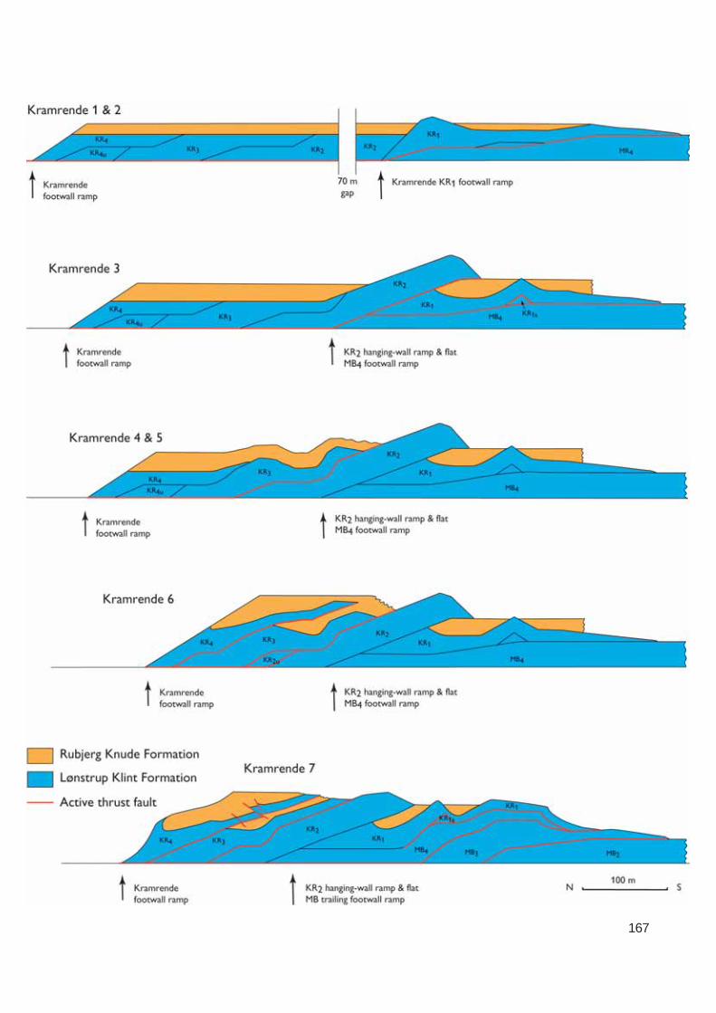
167

168
also developed at the crest of the fault-bend-foldedKR01 thrust sheet. Polyphase diapirism evolved in thetrailing end of the KR03 and KR04 thrust sheets, suchthat the primary thrust-fault framework was partiallydestroyed.
Kramrende Section: summary dataBalanced length (L0): c. 600 mCross-section length (L1): c. 300 mShortening (ΔL): c. 300 mCompression: c. 50%
Comment. The lengths are measured from approxi-mate positions on the footwall ramps bounding theKramrende Section and the data must therefore beregarded as tentative estimates.
Martørv Bakker SectionThe development in the Martørv Bakker Section wasdominated by the translation of a thrust sheet thatwas more than 600 m long and only 20–30 m thick.During nearly 400 m of displacement towards the fore-land, a lower segment transformed into a duplex thatramped at a relatively late stage and created a fault-
Fig. 120. Dynamic model of progressive
deformation in the Martørv Bakker Sectionillustrated in three sequential restoration
cross-sections. The cross-sections demon-strate four stages in the development
between the balanced cross-section and thestructural cross-section (Plate 2). The red
lines indicate the active displacementsur faces in each deformation stage. Note the
significant depression formed in the hang-ing-wall block south of the Martørv Bakker
normal fault. In this depression, diamictitesinterlayered with slump-slides were depo-
sited.
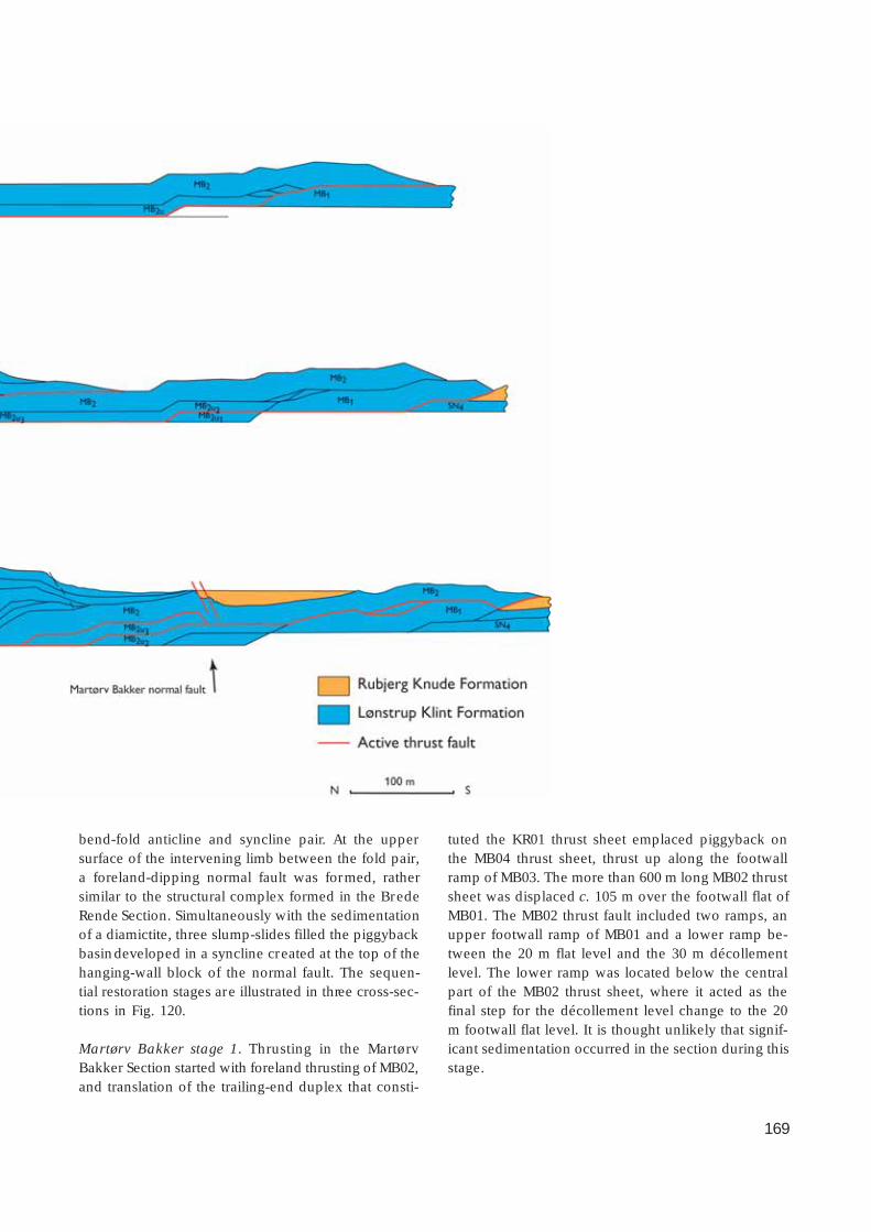
169
bend-fold anticline and syncline pair. At the uppersurface of the intervening limb between the fold pair,a foreland-dipping normal fault was formed, rathersimilar to the structural complex formed in the BredeRende Section. Simultaneously with the sedimentationof a diamictite, three slump-slides filled the piggybackbasin developed in a syncline created at the top of thehanging-wall block of the normal fault. The sequen-tial restoration stages are illustrated in three cross-sec-tions in Fig. 120.
Martørv Bakker stage 1. Thrusting in the MartørvBakker Section started with foreland thrusting of MB02,and translation of the trailing-end duplex that consti-
tuted the KR01 thrust sheet emplaced piggyback onthe MB04 thrust sheet, thrust up along the footwallramp of MB03. The more than 600 m long MB02 thrustsheet was displaced c. 105 m over the footwall flat ofMB01. The MB02 thrust fault included two ramps, anupper footwall ramp of MB01 and a lower ramp be-tween the 20 m flat level and the 30 m décollementlevel. The lower ramp was located below the centralpart of the MB02 thrust sheet, where it acted as thefinal step for the décollement level change to the 20m footwall flat level. It is thought unlikely that signif-icant sedimentation occurred in the section during thisstage.

170
Martørv Bakker stage 2. The MB01 thrust sheet wasdisplaced about 100 m over the foreland of the Stens-næs Section along the leading-edge thrust. The MB01thrust was rooted down to the 20 m flat level, and itcan be traced further on to the 30 m décollement levelby passing the central lower footwall ramp of MB02.Minor adjustments along the hanging-wall flat result-ed in formation of small duplexes along the thrustfault. In the trailing end of the section, the MB03 thrustsheet was thrust up over the footwall ramp of MB02,whereby an antiformal stack was formed due to thefolding that also involved the MB04 and KR01 thrustsheets. At the base of the MB03 thrust sheet, the low-er segments formed an irregular duplex, which ac-centuated the antiformal stack. The accumulated dis-placement ranged up to 290 m.
Martørv Bakker stage 3. The final thrusting of theMartørv Bakker Section was concluded by nearly 100m displacement of the MB02 thrust sheet. The frontalhanging-wall ramp-and-flat was thrust over the piggy-back basin of the SN04 thrust sheet in the StensnæsSection. During the thrusting, the lower segmentMB02u was activated and formed a fault-bend-foldedlower duplex. Above the hanging-wall ramp of thetrailing-end segment (MB02u3), an anticline wasformed at the surface of MB02 and a subsequent syn-cline above the hanging-wall/footwall flat became apiggyback basin.
Martørv Bakker stage 4. The foreland-dipping limb ofthe fold pair at the top of the MB02 thrust sheet devel-oped into a southerly dipping normal fault. The c. 10m deep piggyback basin was filled with diamictiticdeposits and slump-sheets that glided down from thetop of the antiformal stack. Deformation in the Mar-tørv Bakker Section concluded with the steepeningup of the leading-edge thrust structures due to rampbending in the Stensnæs Section.
Martørv Bakker Section: summary dataBalanced length (L
0): 1065 m
Cross-section length (L1): 675 m
Shortening (ΔL): 390 mCompression: 36.6%
Comment. The lengths are measured from the tip ofthe leading-edge hanging-wall ramp to the upper bendof the footwall ramp of the MB04 thrust sheet.
Stensnæs SectionIn the Stensnæs Section, a number of conspicuousflexural slip folds occur which are interpreted to haveresulted from the deformation that accompanied se-quential footwall ramp collapse and subsequent rampdisplacement of minor duplexes. It is significant thatthey occur in relation to the final ramping from thelower 20 m flat level to the upper 10 m flat level. Eightstages have been differentiated in the developmentof the Stensnæs Section, of which stages 2, 4 and 6–8are illustrated by the cross-sections in Fig. 121.
Stensnæs stage 1. In contrast to the Martørv BakkerSection, an initial sediment thickness of 5 m of theRubjerg Knude Formation is thought to have coveredthe Stensnæs Section. It should be noted, however,that typical Lønstrup Formation facies grade upwardsinto typical Rubjerg Knude Formation facies in thisdistal part of the Rubjerg Knude Glaciotectonic Com-plex; the L/R-unconformity is not clearly developed,and location of the formation boundary can be diffi-cult. The affinities of the sediment packet referred toabove are thus debatable.
Stensnæs stage 2. Thrusting in the Stensnæs Sectionwas initiated with c. 100 m displacement of the SN02thrust sheet over the upper flat. The thrust fault rampeddown to the 10 m flat level, which separated the up-per and lower segments of the SN04 thrust sheet, si-multaneously with stacking the SN03 thrust sheet intoa northerly dipping duplex complex along the foot-wall ramp of SN01.
Stensnæs stage 3. Accumulation of the Rubjerg KnudeFormation increased to a sediment thickness of 10 m.Sedimentation was restricted to the piggyback basinof the SN04 thrust sheet, as well as on the forelandsouth of the frontal tip of the SN02 thrust sheet.Stensnæs stage 4. The piggyback basin on the back ofSN04 was sealed in by the overthrusting of the MB02thrust sheet; this is equivalent to stage 3 in the Mar-tørv Bakker Section.
Stensnæs stage 5. As a trailing-end structural complexto the Ulstrup Section, the thrust sheets of the Stens-næs Section were translated together with the UL02thrust sheet over the Ulstrup footwall ramp onto thehanging-wall flat of the foreland. During ramping, theSN01 and SN03 thrust sheets were separated into smallduplex segments. Flexural-slip folding and polyphase

171
UL1 intermediate footwall rampsUlstrup footwall ramp
Stensnæs 2
Ulstrup footwall ramp
MB1SN4
SN4u SN4u SN1 UL2SN1
SN3SN2
Stensnæs 4
Ulstrup footwall ramp
MB2
MB1
SN4u SN4u
SN4 SN3
SN2
SN1 SN1u UL2
?
Stensnæs 6
MB1
SN4u
SN4
SN3 SN2
SN4u SN1 SN1u UL2 UL1
MB2? ?
Stensnæs 7 & 8
Stensnæs ramp
MB2
MB4SN4
SN3 SN2
SN1SN1u UL2
UL1
Lønstrup Klint Formation
Active thrust fault
Rubjerg Knude Formation
100 mN S
Fig. 121. Dynamic model of progressive deformation in the Stensnæs Section illustrated in four sequential restoration cross-sections.The cross-sections demonstrate five of the eight stages in the development described in the text between the balanced cross-section
and the structural cross-section (Plate 2). The red lines indicate the active displacement surfaces in each deformation stage.
hydrodynamic brecciation resulted from the ramping(Figs 53, 57, 58). The accumulated displacement rangedup to 35 m, whereas the length of the hanging-wallflat in the 10 m flat level amounted to 500 m. At theleading edge of thrusting, the UL02 thrust sheet initia-ted the thrusting up over a stepwise ramp.
Stensnæs stage 6. During this stage, about 10 m of theRubjerg Knude Formation was deposited in the pig-gyback basin at the top of the SN02 thrust sheet. The
sedimentation level was probably up to 20 m abovethe L/R-unconformity, inferred from the elevated po-sition of the SN02 thrust sheet. However, this is un-certain and the sediments were either never deposit-ed or eroded away during later thrust elevation. Inthe northern part of the section, the SN04 thrust sheetpropagated up along the footwall ramp of the earliercreated SN02–SN03 duplex. This resulted in fault-bendfolding of the SN04 thrust sheet and its piggybackbasin as well as the overlying MB02 thrust sheet. This

172
stage correlates with stages 3–6 in the Martørv BakkerSection.
Stensnæs stage 7. The SN01 thrust sheet was displacedabout 50 m over its lower segment (SN01u), and togetherthey were thrust onto the footwall ramp-and-flat of theUL02 thrust sheet. During the thrust-fault propagationof the UL02 thrust sheet over the footwall ramp of UL01,the SN01 and SN02 thrust sheets, piggyback translatedon UL02, were bent into c. 30° dipping position. Fi-nally, the SN04 thrust sheet was displaced up alongthe footwall ramp of SN03 during dif ferential duplexformation along the SN04 hanging-wall ramp.
Stensnæs stage 8. The frontal parts of the SN01, SN02and SN03 thrust sheets, as well as the anticlinal crest
of the UL02 thrust sheet (formed above the upper hingeof footwall ramp of UL01), were significantly eroded,and a local piggyback basin was formed above thetransition between the Stensnæs and Ulstrup Sections.To the north of this piggyback basin, the elevatedand exposed tips of the SN02–SN04 thrust sheets grav-ity-slumped out into the basin, where they were de-posited as olistoliths, 1–5 m in size.
Stensnæs Section: summary dataBalanced length (L0): 350 mCross-section length (L1): 180 mShortening (ΔL): 170 mCompression: 48.6%

173
Ulstrup SectionThin-skinned thrusting in the Ulstrup Section involvedthe remarkable translation of extensive, thin thrustsheets over the footwall flat of the foreland. Cohesionof the thrust sheet was probably increased by groundfrost in the upper part of the thrust sheet, while thehanging-wall ramp-and-flat slid on a thin zone of mo-bilised mud. During translation, piggyback sedimen-tation varied considerably. Six stages have been dif-ferentiated in the development of the Ulstrup Section;stages 1–3 and 5 are illustrated by the cross-sectionsin Fig. 122 (see also Fig. 121).
Ulstrup stage 1. Thrusting in the Ulstrup Section initia-ted with frontal ramping of the UL02 thrust sheet overa two-stepped footwall ramp of what was to become
the UL01 thrust sheet. This ramping resulted in the for-mation of two, fault-propagating folded anticlines,which were separated by a shallow, broad syncline.The leading edge of the UL02 hanging-wall ramp wasdisplaced about 25 m over the c. 5–10 m thick RubjergKnude Formation deposited in the foreland (at thetop of UL01). The UL02 hanging-wall flat extendedalong the upper 10 m flat level for about 400 m, termi-nating to the north at the foreland footwall ramp root-ing down to the 20 m décollement level. Thrust pro-pagation up over this ramp formed a hanging-wallanticline at the trailing end of the UL02 thrust sheet.Between the anticline at the trailing end and the anti-cline at the upper footwall ramp of UL01, a piggybackbasin formed in which glaciolacustrine sediments weredeposited to form the small, ephemeral Ulstrup lake.
Fig. 122. Dynamic model of progressive deformation in the
Ulstrup Section illustrated in four sequential restoration cross-sections. The cross-sections demonstrate four of the eight
stages in the development described in the text between thebalanced cross-section and the structural cross-section (Plate
2). The red lines indicate the active displacement surfaces ineach deformation stage.
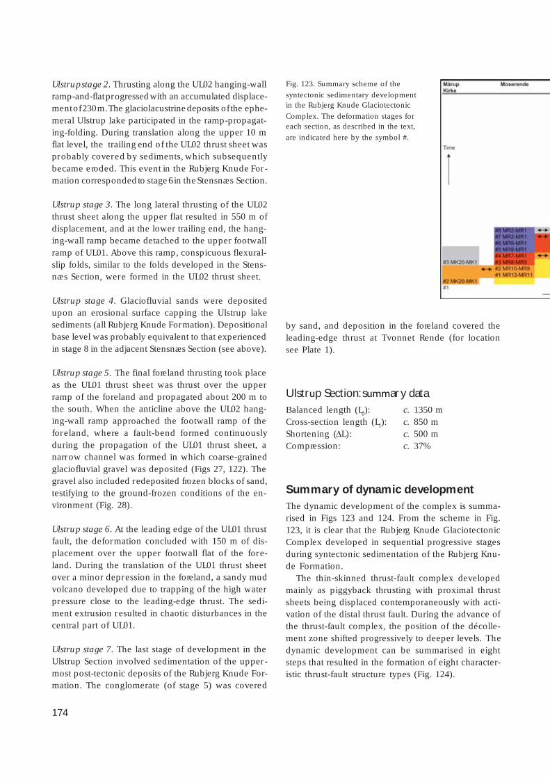
174
Ulstrup stage 2. Thrusting along the UL02 hanging-wallramp-and-flat progressed with an accumulated displace-ment of 230 m. The glaciolacustrine deposits of the ephe-meral Ulstrup lake participated in the ramp-propagat-ing-folding. During translation along the upper 10 mflat level, the trailing end of the UL02 thrust sheet wasprobably covered by sediments, which subsequentlybecame eroded. This event in the Rubjerg Knude For-mation corresponded to stage 6 in the Stensnæs Section.
Ulstrup stage 3. The long lateral thrusting of the UL02thrust sheet along the upper flat resulted in 550 m ofdisplacement, and at the lower trailing end, the hang-ing-wall ramp became detached to the upper footwallramp of UL01. Above this ramp, conspicuous flexural-slip folds, similar to the folds developed in the Stens-næs Section, were formed in the UL02 thrust sheet.
Ulstrup stage 4. Glaciofluvial sands were depositedupon an erosional surface capping the Ulstrup lakesediments (all Rubjerg Knude Formation). Depositionalbase level was probably equivalent to that experiencedin stage 8 in the adjacent Stensnæs Section (see above).
Ulstrup stage 5. The final foreland thrusting took placeas the UL01 thrust sheet was thrust over the upperramp of the foreland and propagated about 200 m tothe south. When the anticline above the UL02 hang-ing-wall ramp approached the footwall ramp of theforeland, where a fault-bend formed continuouslyduring the propagation of the UL01 thrust sheet, anarrow channel was formed in which coarse-grainedglaciofluvial gravel was deposited (Figs 27, 122). Thegravel also included redeposited frozen blocks of sand,testifying to the ground-frozen conditions of the en-vironment (Fig. 28).
Ulstrup stage 6. At the leading edge of the UL01 thrustfault, the deformation concluded with 150 m of dis-placement over the upper footwall flat of the fore-land. During the translation of the UL01 thrust sheetover a minor depression in the foreland, a sandy mudvolcano developed due to trapping of the high waterpressure close to the leading-edge thrust. The sedi-ment extrusion resulted in chaotic disturbances in thecentral part of UL01.
Ulstrup stage 7. The last stage of development in theUlstrup Section involved sedimentation of the upper-most post-tectonic deposits of the Rubjerg Knude For-mation. The conglomerate (of stage 5) was covered
by sand, and deposition in the foreland covered theleading-edge thrust at Tvonnet Rende (for locationsee Plate 1).
Ulstrup Section: summary dataBalanced length (L0): c. 1350 mCross-section length (L1): c. 850 mShortening (ΔL): c. 500 mCompression: c. 37%
Summary of dynamic developmentThe dynamic development of the complex is summa-rised in Figs 123 and 124. From the scheme in Fig.123, it is clear that the Rubjerg Knude GlaciotectonicComplex developed in sequential progressive stagesduring syntectonic sedimentation of the Rubjerg Knu-de Formation.
The thin-skinned thrust-fault complex developedmainly as piggyback thrusting with proximal thrustsheets being displaced contemporaneously with acti-vation of the distal thrust fault. During the advance ofthe thrust-fault complex, the position of the décolle-ment zone shifted progressively to deeper levels. Thedynamic development can be summarised in eightsteps that resulted in the formation of eight character-istic thrust-fault structure types (Fig. 124).
Fig. 123. Summary scheme of the
syntectonic sedimentary developmentin the Rubjerg Knude Glaciotectonic
Complex. The deformation stages foreach section, as described in the text,
are indicated here by the symbol #.

175
1. Long lateral translation of a thin thrust sheet tookplace over the foreland. The ramp was rooted inthe uppermost shallow décollement level 1 at adepth of c. 10 m from the top surface.
2. Ramps became rooted in décollement level 2, andthe increase in ramp height, amounting to about20 m, is regarded to be the cause of the duplexfolding at ramp collapse.
3. The hanging-wall anticlines became dominant struc-tures with hinterland-dipping piggyback thrustsheets on the back limb. As the ramps extendeddown into décollement level 3, the height of theramps increased and consequently the hanging-wall anticlines increased in size.
4. The antiformal stack developed, which includedlong-distance translated piggyback thrust sheetsthat were folded in a hanging-wall anticline. Inrelation to the antiformal stack, foreland-dippingthrust faults occur that were accompanied by nor-mal faults.
5. The prominent imbricate fan formed above décol-lement level 2. The initially gently to moderatelydipping imbricated thrust sheets were re-orientat-ed into steeply dipping positions due to lateraltranslation of the imbricate fan along décollementlevel 3.
6. This step involved the subsequent deformation ofthe lower duplex segment not incorporated in theimbricate fan. This lower duplex segment was im-bricated and the sub-segments were displaced in-to a duplex stack during push from behind by a
progressing hanging-wall ramp, rooting in décol-lement level 3.
7. This step involved differential duplex stacking andimbrication of thrust-fault sheets. The piggybackbasins vary in elevation due to differences in du-plex stacking. Furthermore, the variation in duplexstacking reflects the shift from décollement level 3to 4 (corresponding to a shift in the décollementsurface from 30 to 40 m).
8. The fault-bend-folded duplex units were formed.The formation of these duplex units was only pos-sible because the four thrust-fault flat levels haddeveloped, and thus the duplexes could be stackedand subsequently fault-bend-folded during maxi-mum compression and translation along décolle-ment level 4 (Fig. 124).
The thickness of sediments that accumulated contem-poraneously in tectonically correlated piggyback ba-sins decreases from north to south. Thus the depo-centre was situated in front of the last activated thrustsection, and the depocentre gradually shifted to a moreand more distal position. Correlation of the syntec-tonic progressive development of the complex showsthat sedimentation was contemporaneous with thrust-ing rather than there being an alternation betweenperiods of active thrust faulting and periods of depo-sition. Furthermore, it indicates that the ice marginwas not melting back during the formation of the com-plex but advanced in a continuous progressive gravi-ty-spreading process.

176
Ice
Fault-bend-folded duplex
Imbricated duplex stack
Duplex stack
Imbricate fan
Antiformal stack
Hanging-wall anticline
Duplex folds at ramp collapse
Foreland translated thrust sheet
Distance
Tim
e
SN
Fig. 124. Model of thrust-fault structure types formed during the progressive deformation of the thin-skinned glacio-
tectonic thrust-fault complex. The model outlines a progressive development in eight steps resulting in the formationof eight characteristic thrust-fault structure types, the first to develop earliest and continuously in the distal part of the
complex, and the last to be formed in the most proximal part of the complex (see text for details).
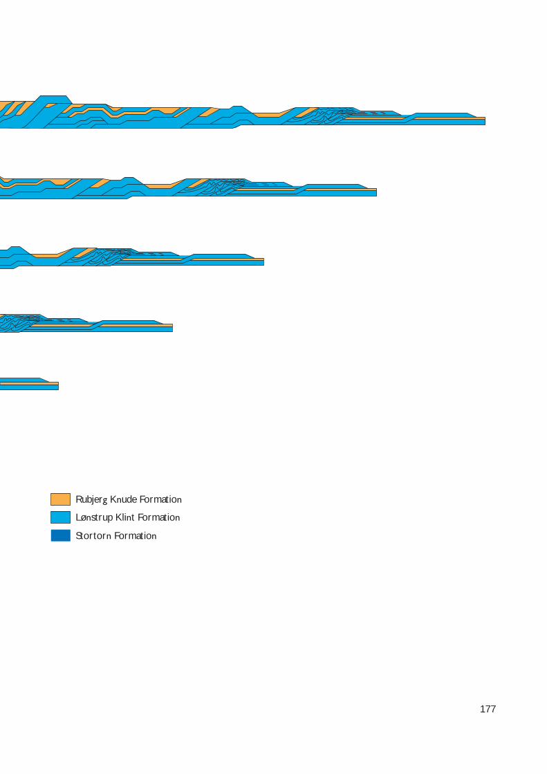
177
Lønstrup Klint Formation
Rubjerg Knude Formation
Stortorn Formation
178
Discussion
The observations that form the basis for the descrip-tion of the structural geology, mechanical behaviourand dynamic development of the Rubjerg Knude Gla-ciotectonic Complex, raise important questions withrespect to understanding the framework and natureof thin-skinned thrusting related to glacial deforma-tion; seven topics have been selected for further discus-sion below. The basis for understanding a structuralcomplex is to describe the tectonic architecture andthe range of structures it contains from microscopic tomacroscopic scale. The discussion of thrust-fault archi-tecture leads to evaluation of the reliability of the balan-ced cross-section. Consideration of thrust brecciationand diapirism leads naturally to a focus on the thrust-fault dynamics, and the significance of the rate of defor-mation. The dynamics associated with the syntecton-ic deposits and the formation of piggyback basins meritdiscussion, as does the interpretation of a proglacialcontra subglacial deformational setting. The final topicdeals with the geological setting of the complex, inclu-ding the timing of the event that created it.
Thrust-fault architectureA prerequisite for understanding the thrust-fault ar-chitecture is a familiarity with the terminology (seeAppendix 2). The macroscopic structures encounteredin thin-skinned orogenic belts are all recognisable in theglaciotectonic complex. Mesoscopic structures suchas folds and faults are similarly recognisable. However,small-scale structures such as joints, cleavage and fabricare more difficult to recognise (except for hydrody-namic brecciation), and this may be one of the majordif ferences between soft sedimentary deformation andhard-rock deformation.
It seems likely that joints and fractures in soft sedi-ments would be able to re-heal after deformation. Thus,a large number of minor reverse faults must haveformed in thrust sheets during ramp propagation (Fig.67), but appear to have disappeared again after sub-sequent thrust sheet propagation along the flat, asthey have not been observed with the exception of thein situ positions related to ramp bend (Fig. 85). Thereis an approximation to a right-angle relationship be-tween the footwall ramp and the back-thrust faults,
which indicates that an increase in the dip of the foot-wall ramp results in a decrease in the dip, in the op-posite direction, of the back thrust. Moreover, a steeperand higher footwall ramp also corresponds to an in-crease in displacement along the back-thrust fault. Thusone can regard the KR01 (Kramrende) back-thrust faultsas structures related to initial faulting in the progres-sive deformation (Fig. 67), and the KR04 back-thrustsplay faults as a structural element related to a devel-oped phase of progressive thrust-fault deformation(Fig. 72). Major back thrusting at the back of SR02(Fig. 84) represents a mature phase in the progressivethrust faulting. The apparent lack of joints and frac-tures reflecting ramp propagation could probably beexplained as having been absorbed in the hydrody-namic brecciation process.
Among the structural elements analysed during theinterpretation of the balanced cross-section, the du-plex structures create the most interesting problems.Firstly, the interpretation of the duplex imbricates inthe Stensnæs Section provides an explanation for thecomplicated fold framework. Secondly, the interpre-tation of the duplex below the frontal part of the Stor-torn Section links the hidden duplex segments at thebase of the Grønne Rende Section with the duplexstacking below ST01–ST03. Thirdly, the normal faultscan be interpreted to have been related to the ramp-ing of lower duplex segments. If the normal faults areregarded as foreland-dipping faults or part of a fore-land-dipping duplex, the model for duplex formationsuggested by Contreras & Sutter (1997) may be rele-vant for the understanding of the foreland-dippingfaults. In their model for formation of foreland- orhinterland-dipping duplexes, they considered two fac-tors: u = distance of displacement along the upperflat, and s = length of duplex segment. In a regimewhere the ratio u/s is greater than one (u/s > 1), fore-land-dipping duplexes are formed; in a regime whereu/s < ½, hinterland-dipping duplexes are formed. Inregimes where ½ < u/s < 1 or u/s = 1, antiformalstacks or angular antiformal stacks, respectively, areformed. This corresponds well to the interpretationpresented here of the Rubjerg Knude cross-section,where most thrust sheets are displaced by less thantheir length, and consequently the main orientationof thrust sheets is hinterland dipping. According tothe model of Contreras & Sutter (1997), foreland-dip-

179
ping duplexes are formed when a duplex segment isdisplaced along an intermediate or upper flat for adistance equal to, or more than, its length. A conse-quence of this is that a roofing thrust sheet will bedisplaced in front of the foreland-dipping upper foot-wall flat, where normal faulting will take place. Thisis interpreted to be the case for the normal faults inthe Martørv Bakker and Brede Rende Sections (seeFig. 66). The normal fault developed in the StenstueRende Section may also be regarded as an expressionof the latter regime in the suggested model. A fore-land-dipping feature may well reflect the foreland-dip-ping limb of a hanging-wall anticline formed above alaterally displaced hanging-wall ramp. However, thenormal fault-displaced thrust sheet must be thrust overthe duplex segment before it was thrust faulted togetherwith its roofing thrust sheet, and then as translationcontinued attached to the hanging-wall flat until thedisplacement was concluded by the normal faultingover the tip of the duplex segment.
The consideration of duplex formation naturallyleads to a focus on the changes in décollement levels.When a duplex segment is formed, there would nor-mally be an early décollement surface at a shallowlevel, succeeded by a shift to a deeper level connect-ed with a new footwall ramp. The upper décollementlevel (the 10 m level or corresponding gently dippingramp to the leading edge) was probably the first to beformed in the proximal part of the complex and prob-ably also the last to form in the distal part (Fig. 124).From the cross-section, it is indicated that the 10 mdécollement level extended for about 1 km, but end-ed up with a distance of only 600 m. The 20 m décol-lement level was the next to take over, and during theestablishment of a related ramp, footwall ramp imbri-cation progressed, modifying the ramp transition con-necting the two décollement levels. The length of thisdécollement level might have been of the same scale,but only c. 400 m is preserved as a lower footwall flat.The 30 m flat level is the dominant décollement levelextending from the middle of the Martørv Bakker Sec-tion to the middle part of the Stortorn Section, wherefinally the 40 m décollement level was developed.Note that the present-day position of the lowermostdécollement surface is at about 45 m b.s.l. due to theregional, very gentle dip to the north of the L/R-un-conformity that serves as the reference level, corre-sponding to the 0 m flat level. From the cross-section,it can be seen that the dips of the ramps increase fromgentle (5–15°) in the zone between the upper surfaceflat to the 10 m flat level, to 25° dips between the 10
and 20 m levels, and reaching up to 35° between the20 and 30 m flat levels. The ramp dips with steeperangles in the cross-section, arise from over-steepen-ing or superimposed tilting during ramp propagation(Fig. 9). Thus, in the proximal part of the complex,dips between 35° and 45° are interpreted as the pri-mary dips of ramps rooting down to the deepest dé-collement level at 40 m, which is incorporated in themodel for the fold-imbricate duplex units. The increas-ing dips of ramps are interpreted to have resulted fromthe increase in fracture angle as a function of increasein normal stress (change of levels) and increase inshear stress (increasing force required to move thrustsheets). This is implied from the shape of the Mohr-envelope in the Mohr diagram (Hobbs et al. 1976),and it is suggested to be a basic relationship for glacio-tectonic fracture and fault deformation (Pedersen 1996).
Balanced cross-sectionIn the balanced cross-section, the changes in dip ang-les are responsible for the insertion of a number ofsmall triangular-shaped duplex segments, which areincorporated in the geometric construction and anno-tated as splints (horses) (Plate 2). It is not known howmany splints exist in reality. A few have been recog-nised as structural identities (KR01
S in Kramrende),
but it is likely that space deficits or excesses havebeen absorbed in mud-mobilisation or differentialsmall-scale anastomosing fracturing. Dif ferential frac-turing and thrust-fault formation with a spacing of only1 m has been documented in the Moserende Section(Fig. 27), indicating that the duplex segmentation doesexist. Hence it is probable that a much more differen-tial translation took place than is indicated in the cross-sections of the dynamic model of thrust-fault propa-gation (Fig. 112).
The reliability of the approximations in construc-tion inherent in a balanced cross-section is foundedin the area balance. The main calculation of the bal-ance indicates that the shortening amounts to approx-imately 50%, with L
0 = 12 km and L
1 = 6 km. The area
of the L0 cross-section (L
0 multiplied by stratigraphic
thickness) amounts to 340 000 m2, and the area of theL
1 cross-section (L
1 multiplied by measured thickness
of the retrodeformed cross-section) is 382 500 m2. Thedif ference amounts to 11%, which is interpreted as aconsequence of the erosion of the thrust sheets in theproximal part of the complex (Grønne Rende Section– Ribjerg Section). The detailed calculations of areas
180
for the area balance are summarised in Table 1, anddocumented in Plates 2A and 2B. The amount of ero-sion indicated from the area balance differs markedlyfrom the 80% erosion estimate by Gry (1941), and sup-ports the argument that Gry’s cylindrical thrust-faultmodel was incorrect.
Considering the amount of erosion, the questionarises: why is the preservation potential so great? Threefactors are suggested here to answer this: (1) the steep-ly orientated thrust sheets were partly packed by thesand fill in the piggyback basins, (2) the thrust-faultdeformation resulted in a strain hardening that con-solidated the complex, and (3) as the sole of the ap-proaching ice sheet advanced across the proximal partof the complex, the over-pressured pore water mi-grated from the hanging-wall ramps and flats of thethrust sheets to the hanging-wall flat of the ice sheet,facilitating the over-thrusting of the footwall block whichsubsequently comprised the thrust-fault complex.
Thrust brecciation and diapirismIn order for a thrust sheet to move, a fracture must becreated that can develop into a plane of thrusting.The initial fracture is formed when the failure limit isreached in a system subjected to pressure (loadingand lateral compression). A recurring question, and anapparent conflict in reasoning, is why fault planesdevelop, leaving the rest of the thrust sheet preserved?Since the sedimentary unit forming a thrust sheet issubjected to the same amount of confining pressure,it might be expected that a muddy mass of collapsedsedimentary units just as well could have been theresult?
It is well known that an increase in pore-water pres-sure results in failure and initialisation of fractures alongsurfaces of anisotropy, as described for orogenic sys-tems by Hubbert & Rubey (1959). However, in softsedimentary deformation with lower confining pres-sure and smaller shear strength, as well as smallercoefficient of internal friction, the limits of fractureformation and complete collapse are much narrower.The structures developed in the Ulstrup Section re-flect these conditions. The anastomosing jointing andmud mobilisation at the tip of the UL01 thrust sheetreflect the stage of near collapse (Fig. 49). The thickzone of hydrodynamic brecciation along the hanging-wall flat reflects the same tendency towards collapse,and speculations about the influence of ground-fro-zen conditions on the preservation of the thin thrust
sheets during translation over the foreland are rele-vant. Ground-frozen conditions are interpreted to haveaffected that part of the thrust sheets elevated abovethe ground surface; the freezing of the sediments inthe thrust sheet may result in more brittle behaviour,whereby cracks formed (Figs 44, 46). However, dueto the high pore pressure maintained along the hang-ing-wall flat, the cracks were filled with sand pumpedinto the cracks by the over-pressured pore water fromthe base of the thrust sheet.
Hydrodynamic brecciation is evidently related tothe hanging-wall ramp-and-flat. Brecciation was ini-tiated at an episedimentary stage with the formationof ball-and-pillow structures due to sediment load-ing. When the loading increased by over-thrusting,the ball-and-pillow formation progressed further andhydrodynamic brecciation was concentrated at thehanging-wall flat. Small-scale mud diapirism took place,with chaotic folding developing into polydiapirs (Figs54, 55, 77, 78, 86, 88). Polydiapirism and mud-mobili-sation are considered to have developed simultane-ously and with an increasing degree of disorderingand size of diapir in progressive stages of deforma-tion. Many of the mesoscopic diapir structures recog-nised in the Rubjerg Knude Glaciotectonic Complexcan be compared with the multi-wavelength gravitystructures described in the model analysis by Wein-berg & Schmeling (1992). The formation of large-scalediapirs is suggested to have been related to thrust-fault deformation of a deep-seated hanging-wall flatthat propagated up to surface level along a set of rel-atively steep footwall ramps. During propagation upalong a lower ramp to an intermediate flat, and ramp-ing from the 20 m intermediate flat level to the 10 mflat level, polysequential hanging-wall anticlinesformed, and were subsequently destroyed by mud-mobilisation initiated from the deep-seated thrust zoneof the hanging-wall flat. Some of the soft sedimentaryxenoliths floating in the mud diapirs can be viewedas relicts of anticline crests (Fig. 74). Staircase-like ramppropagation is indicated for the Kramrende diapir andthe Sandrende diapir, but is not so obvious in thecase of the Brede Rende diapir. Intrusive remobilisedmud is evidently related to the footwall ramp propa-gated hanging-wall flat of GR01, and the mud mobili-sation in the thrust sheets of the Stortorn and Moser-ende Sections are all easily identified with sequentialramping from the deepest décollement level.
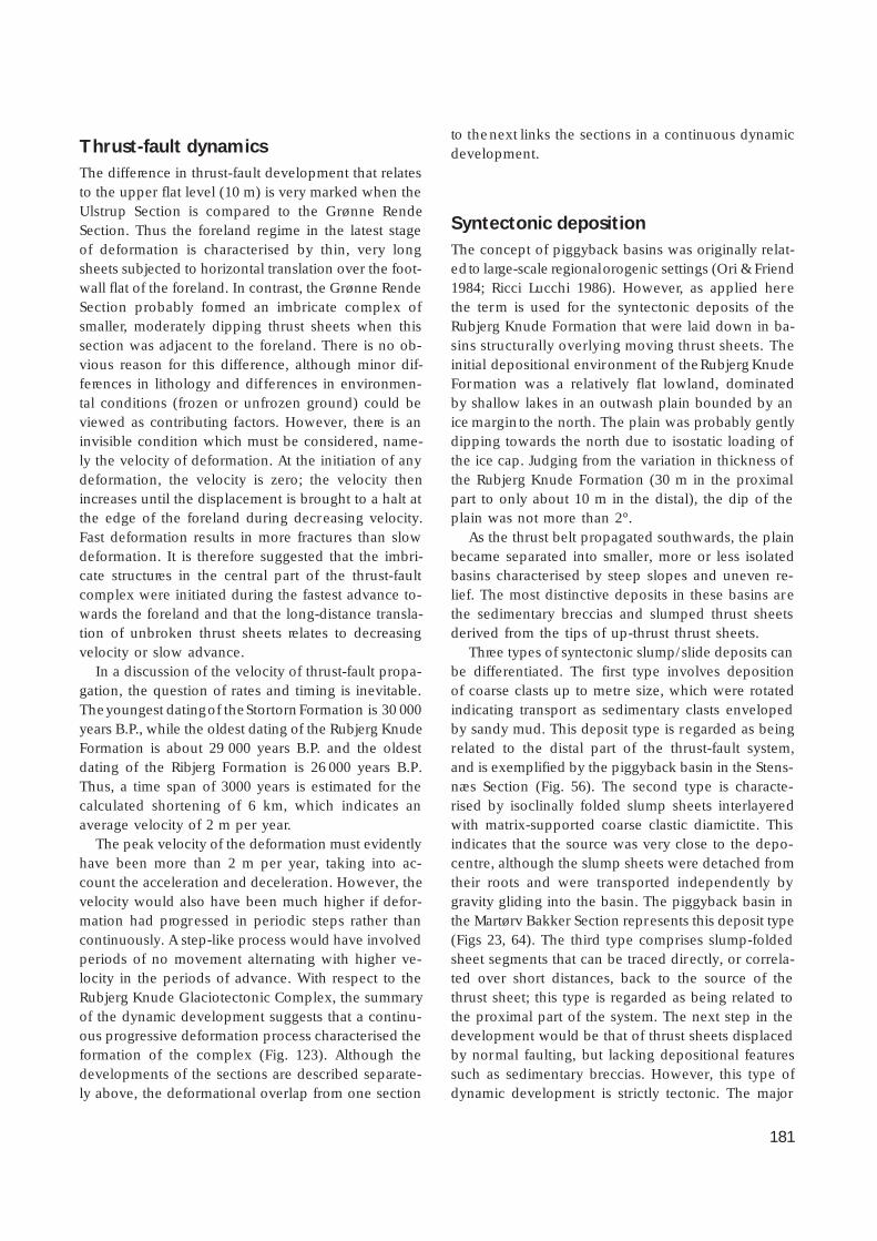
181
Thrust-fault dynamicsThe difference in thrust-fault development that relatesto the upper flat level (10 m) is very marked when theUlstrup Section is compared to the Grønne RendeSection. Thus the foreland regime in the latest stageof deformation is characterised by thin, very longsheets subjected to horizontal translation over the foot-wall flat of the foreland. In contrast, the Grønne RendeSection probably formed an imbricate complex ofsmaller, moderately dipping thrust sheets when thissection was adjacent to the foreland. There is no ob-vious reason for this difference, although minor dif-ferences in lithology and dif ferences in environmen-tal conditions (frozen or unfrozen ground) could beviewed as contributing factors. However, there is aninvisible condition which must be considered, name-ly the velocity of deformation. At the initiation of anydeformation, the velocity is zero; the velocity thenincreases until the displacement is brought to a halt atthe edge of the foreland during decreasing velocity.Fast deformation results in more fractures than slowdeformation. It is therefore suggested that the imbri-cate structures in the central part of the thrust-faultcomplex were initiated during the fastest advance to-wards the foreland and that the long-distance transla-tion of unbroken thrust sheets relates to decreasingvelocity or slow advance.
In a discussion of the velocity of thrust-fault propa-gation, the question of rates and timing is inevitable.The youngest dating of the Stortorn Formation is 30 000years B.P., while the oldest dating of the Rubjerg KnudeFormation is about 29 000 years B.P. and the oldestdating of the Ribjerg Formation is 26 000 years B.P.Thus, a time span of 3000 years is estimated for thecalculated shortening of 6 km, which indicates anaverage velocity of 2 m per year.
The peak velocity of the deformation must evidentlyhave been more than 2 m per year, taking into ac-count the acceleration and deceleration. However, thevelocity would also have been much higher if defor-mation had progressed in periodic steps rather thancontinuously. A step-like process would have involvedperiods of no movement alternating with higher ve-locity in the periods of advance. With respect to theRubjerg Knude Glaciotectonic Complex, the summaryof the dynamic development suggests that a continu-ous progressive deformation process characterised theformation of the complex (Fig. 123). Although thedevelopments of the sections are described separate-ly above, the deformational overlap from one section
to the next links the sections in a continuous dynamicdevelopment.
Syntectonic depositionThe concept of piggyback basins was originally relat-ed to large-scale regional orogenic settings (Ori & Friend1984; Ricci Lucchi 1986). However, as applied herethe term is used for the syntectonic deposits of theRubjerg Knude Formation that were laid down in ba-sins structurally overlying moving thrust sheets. Theinitial depositional environment of the Rubjerg KnudeFormation was a relatively flat lowland, dominatedby shallow lakes in an outwash plain bounded by anice margin to the north. The plain was probably gentlydipping towards the north due to isostatic loading ofthe ice cap. Judging from the variation in thickness ofthe Rubjerg Knude Formation (30 m in the proximalpart to only about 10 m in the distal), the dip of theplain was not more than 2°.
As the thrust belt propagated southwards, the plainbecame separated into smaller, more or less isolatedbasins characterised by steep slopes and uneven re-lief. The most distinctive deposits in these basins arethe sedimentary breccias and slumped thrust sheetsderived from the tips of up-thrust thrust sheets.
Three types of syntectonic slump/slide deposits canbe differentiated. The first type involves depositionof coarse clasts up to metre size, which were rotatedindicating transport as sedimentary clasts envelopedby sandy mud. This deposit type is regarded as beingrelated to the distal part of the thrust-fault system,and is exemplified by the piggyback basin in the Stens-næs Section (Fig. 56). The second type is characte-rised by isoclinally folded slump sheets interlayeredwith matrix-supported coarse clastic diamictite. Thisindicates that the source was very close to the depo-centre, although the slump sheets were detached fromtheir roots and were transported independently bygravity gliding into the basin. The piggyback basin inthe Martørv Bakker Section represents this deposit type(Figs 23, 64). The third type comprises slump-foldedsheet segments that can be traced directly, or correla-ted over short distances, back to the source of thethrust sheet; this type is regarded as being related tothe proximal part of the system. The next step in thedevelopment would be that of thrust sheets displacedby normal faulting, but lacking depositional featuressuch as sedimentary breccias. However, this type ofdynamic development is strictly tectonic. The major

182
slump fold occurring in the Stenstue Rende Section(Fig. 89) may be regarded as a transition from a sedi-mentary to a tectonic regime. The deposition of recog-nisable thrust-sheet tips in the piggyback basins sup-ports the concept of a continuous thrust-fault process.
Proglacial and subglacial deformationGlaciotectonic analyses distinguish between deforma-tion generated in proglacial and in subglacial regimes(Aber 1982; Croot 1988; Aber et al. 1989; Pedersen 1993,1996, 2000). It has already been argued that the thin-skinned thrust-fault deformation of the Rubjerg KnudeGlaciotectonic Complex is an example of proglacialdeformation. The key evidence for this is the presenceof intimately associated syntectonic piggyback basins.These basins must have been situated in front of theice margin, with sedimentation taking place under openwater, simultaneously with thrust-fault propagation.
However, the subglacial deformation is representedlocally by the 1 m thick glacitectonite occurring belowthe glaciotectonic unconformity that truncated thethrust-fault complex. This is found in the glaciolacu-strine beds at the top of the UL02 thrust sheet in thenorthern part of the Ulstrup Section. It can be arguedthat here the subglacial deformation penetrated downa depth of c. 5 m below the glaciotectonic unconform-ity. Mud diapirism and hydrodynamic brecciation oc-curred in this setting, probably caused by loading whenthe ice sheet overrode the sediments. The focus ofsubglacial deformation is at the Blå-unconformity (Fig.32). In the northernmost 300 m of the cross-section,the effects of mud mobilisation increase to a point atwhich primary sedimentary as well as early structuralfeatures are completely destroyed. This phase of de-formation is interpreted to have taken place while thesole of the frontal part of the ice sheet was fixed tothe trailing end of the thrust-fault complex. This alsoimplies that the velocity of the thrust faulting was equalto the advance of the ice sheet. The advance of theice-sheet load corresponds to the mechanics of grav-ity spreading (Pedersen 1987). The increasing propa-gating stress resulted in increasing mud mobilisation,and subsequently the overpressure was transmittedlaterally by the mud fluid towards the foreland. Themechanism might well be compared to squeezingtoothpaste out of its tube.
At a certain stage, the fluid pressure was released,probably due to migration of all the hydrodynamicbreccias, and the mobilised mud consolidated. Sub-
sequent to consolidation, the frontal sole of the ice-sheet released contact with the Blå-unconformity andpropagated over the thrust-fault complex formed inthe foreland of the ice margin. During this process,subglacial shearing affected the top of the structure-less consolidated mud, and anastomosing as well asplane-parallel shear fractures were formed (Fig. 32).
In soft sediment structural geology, the gravity-spreading model has been successfully applied to thegeological setting of the mud lumps in the MississippiDelta (Morgan et al. 1968; Pedersen 1987; Aber et al.1989). It could therefore be suggested that a gravity-spreading model due to clastic progradation might bethe deformation mechanism. However, there is noknown delta setting at this time/place that could haveprovided the basis for this model, and furthermore,the sand units observed here only reach a third of thethickness of the 100 m delta-sand units in the Missis-sippi Delta setting. Finally, the presence of the glacio-tectonic unconformity and related glacitectonite is in-compatible with a sand sediment-spreading process.
Although a delta setting has not been document-ed, it might be suggested that a slope similar to thatof a megascopic delta foreset existed, and that thedeformation was caused by major gravity gliding onthis slope, or was simply due to uplift in the hinter-land. However, this is not considered likely. The iso-static rebound documented from the elevation of theVendsyssel Formation reaches 60 m a.s.l. To this mustbe added the uplift due to the lowering of sea level;the area in the hinterland was thus an area of subsi-dence rather than uplift. Structurally, a gravity-glidingmodel would provide extensional normal fault sys-tems in the trailing end of the thrust-fault complex(Pedersen 1987). This is not compatible with the ob-served increase in compressional structures in the hin-terland, as documented in the cross-section and indi-cated by the balanced cross-section; a gravity-glidingmodel for the complex can therefore be rejected.
Such larger glaciotectonic complexes are often soimpressive that some geologists suggest that they wereformed by orogenic activity (Lykke-Andersen 1992;K. Binzer, personal communication 1997). Disregar-ding the obvious glacial geological indications, thereare two features that distinguish glaciotectonic com-plexes from basement-involved deformation: (1) thesuperficial detachment, and (2) the rate of translation.In the Rubjerg Knude Glaciotectonic Complex, thereare no infracrustal rocks involved and the thrust sheetsare not rooted down into a deep-seated hinterlandsource. The lowermost detachment level is 40 m be-

183
low the reference level, which is more or less coinci-dent with present sea level, and there are no indica-tions that the deformation extended below the 40 mlevel. The velocity of thrust-sheet motion in orogenicmountain ranges is of the order of 1 cm per year (Wilt-scko & Dorr 1983). In glaciotectonic systems, the ve-locity can be up to 100 times as fast, as documentedby the velocity estimate of 2 m per year for the Ru-bjerg Knude Glaciotectonic Complex.
Glacial geological conditionsThe Rubjerg Knude Glaciotectonic Complex is inter-preted to have formed due to the advance of the Nor-wegian Ice in the late Middle Weichselian. The Nor-wegian Ice melted back at the beginning of Late Weich-selian time and was succeeded by a renewed advanceof the Scandinavian Ice Sheet from central Sweden. Inthat part of Denmark east and north of the Main Sta-tionary Line (Figs 1, 12), the direction of this advancewas towards the south-west and the advance is thusreferred to as the NE-Ice (Houmark-Nielsen 1987). Theeastward advance of this ice towards Vendsyssel pro-bably formed the N–S-trending hilly landscape namedJyske Ås, the formation of which was contemporane-ous with deposition of the outwash plain representedby the Ribjerg Formation. When the NE-Ice advancereached the Rubjerg Knude Glaciotectonic Complex,it only resulted in minor superimposed deformation.The oblique orientation of the fold axis of the mega-slump in the Stenstue Rende Section might be due tosuch superimposed deformation, but in general very
few glaciotectonic disturbances can be related to theNE-Ice advance. That overriding by the NE-Ice had solittle ef fect may be attributed to strain hardening dueto the preceding deformation, or the smoothing outof the landscape by the former glaciotectonic uncon-formity, which would facilitate the second overridingof the complex. Ground-frozen conditions could alsohave been a factor, since this would have preventeddrainage from the ice sheet through the substratum,resulting in high pore-water pressures at the sole ofthe ice. The effect of this would have been to facili-tate easy and fast propagation over the complex, al-though it by then formed a hill in the landscape.
The Norwegian Ice produced a hill-and-hole pairwith Rubjerg Knude as the hill and the depressionextending from Lønstrup northwards as the hole. Im-mediately after the melting back of the NE-Ice, thelandscape was covered by the Vendsyssel Formation.A contour map of the base of the Vendsyssel Forma-tion (Fig. 125) thus provides a picture of the geomor-phology of the young glacial landscape unaffected bythe succeeding 15 000 years of erosion. In Fig. 125,the hill-and-hole pair is readily identified and the gen-eral E–W morphological trends are well represented.To the east, this trend is truncated by a strong SE–NWhill-and-hole geomorphology, related to the NE-Ice.The trend of the thrust-fault belt of the Rubjerg Knu-de Glaciotectonic Complex can be followed from thecoastline to the east for about 2.5–5 km. The easternfringe of the complex has been eroded down to sealevel, probably by the NE-Ice, and subsequently con-cealed by the Vendsyssel Formation.

184
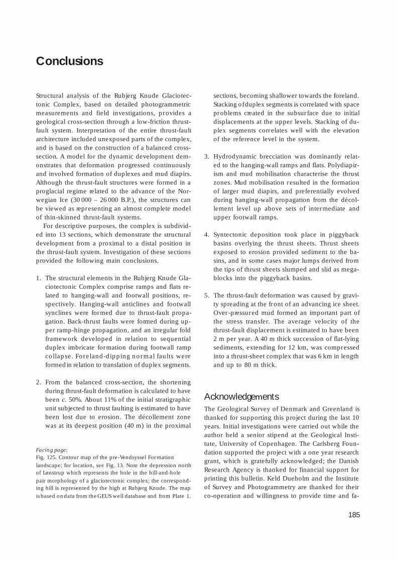
185
Facing page:Fig. 125. Contour map of the pre-Vendsyssel Formation
landscape; for location, see Fig. 13. Note the depression northof Lønstrup which represents the hole in the hill-and-hole
pair morphology of a glaciotectonic complex; the correspond-ing hill is represented by the high at Rubjerg Knude. The map
is based on data from the GEUS well database and from Plate 1.
Conclusions
Structural analysis of the Rubjerg Knude Glaciotec-tonic Complex, based on detailed photogrammetricmeasurements and field investigations, provides ageological cross-section through a low-friction thrust-fault system. Interpretation of the entire thrust-faultarchitecture included unexposed parts of the complex,and is based on the construction of a balanced cross-section. A model for the dynamic development dem-onstrates that deformation progressed continuouslyand involved formation of duplexes and mud diapirs.Although the thrust-fault structures were formed in aproglacial regime related to the advance of the Nor-wegian Ice (30 000 – 26 000 B.P.), the structures canbe viewed as representing an almost complete modelof thin-skinned thrust-fault systems.
For descriptive purposes, the complex is subdivid-ed into 13 sections, which demonstrate the structuraldevelopment from a proximal to a distal position inthe thrust-fault system. Investigation of these sectionsprovided the following main conclusions.
1. The structural elements in the Rubjerg Knude Gla-ciotectonic Complex comprise ramps and flats re-lated to hanging-wall and footwall positions, re-spectively. Hanging-wall anticlines and footwallsynclines were formed due to thrust-fault propa-gation. Back-thrust faults were formed during up-per ramp-hinge propagation, and an irregular foldframework developed in relation to sequentialduplex imbricate formation during footwall rampcollapse. Foreland-dipping normal faults wereformed in relation to translation of duplex segments.
2. From the balanced cross-section, the shorteningduring thrust-fault deformation is calculated to havebeen c. 50%. About 11% of the initial stratigraphicunit subjected to thrust faulting is estimated to havebeen lost due to erosion. The décollement zonewas at its deepest position (40 m) in the proximal
sections, becoming shallower towards the foreland.Stacking of duplex segments is correlated with spaceproblems created in the subsurface due to initialdisplacements at the upper levels. Stacking of du-plex segments correlates well with the elevationof the reference level in the system.
3. Hydrodynamic brecciation was dominantly relat-ed to the hanging-wall ramps and flats. Polydiapir-ism and mud mobilisation characterise the thrustzones. Mud mobilisation resulted in the formationof larger mud diapirs, and preferentially evolvedduring hanging-wall propagation from the décol-lement level up above sets of intermediate andupper footwall ramps.
4. Syntectonic deposition took place in piggybackbasins overlying the thrust sheets. Thrust sheetsexposed to erosion provided sediment to the ba-sins, and in some cases major lumps derived fromthe tips of thrust sheets slumped and slid as mega-blocks into the piggyback basins.
5. The thrust-fault deformation was caused by gravi-ty spreading at the front of an advancing ice sheet.Over-pressured mud formed an important part ofthe stress transfer. The average velocity of thethrust-fault displacement is estimated to have been2 m per year. A 40 m thick succession of flat-lyingsediments, extending for 12 km, was compressedinto a thrust-sheet complex that was 6 km in lengthand up to 80 m thick.
AcknowledgementsThe Geological Survey of Denmark and Greenland isthanked for supporting this project during the last 10years. Initial investigations were carried out while theauthor held a senior stipend at the Geological Insti-tute, University of Copenhagen. The Carlsberg Foun-dation supported the project with a one year researchgrant, which is gratefully acknowledged; the DanishResearch Agency is thanked for financial support forprinting this bulletin. Keld Dueholm and the Instituteof Survey and Photogrammetry are thanked for theirco-operation and willingness to provide time and fa-

186
cilities at the photogrammetric instrument at the Tech-nical University of Denmark.
Frants von Platen-Hallermund is thanked for assist-ance with the ARC-INFO transformation and ARC-VIEWediting, which provided the graphic display of Plates1 and 2. Alice Rosenstand and Benny M. Schark helpedin drafting the figures, and the staff of the Graphic
Section at GEUS are thanked for technical support.I am indebted to A.K. Higgins for reading the first
draft of this manuscript, to two anonymous refereesand the editor, Jon R. Ineson, for their constructiveand helpful comments on the manuscript, and to mywife, Gunver K. Pedersen, for support and inspiringdiscussions during the progress of this work.
References
Aaris-Sørensen, K. 1995: Palaeoecology of a Late Weichselianvertebrate fauna from Nørre Lyngby, Denmark. Boreas 24,
355–365.Aaris-Sørensen, K. & Petersen, K.S. 1984: A late Weichselian find
of polar bear (Ursus maritimus Phipps) from Denmark andreflections on the paleoenvironment. Boreas 13, 29–33.
Aber, J.S. 1982: Model for glaciotectonism. Bulletin of the Geolo-gical Society of Denmark 30, 79–90.
Aber, J.S. (ed.) 1993: Glaciotectonics and mapping glacial depos-its. Canadian Plains Proceedings 25(1), 310 pp. Canadian Plains
Research Center, University of Regina, Canada.Aber, J.S., Croot, D.G. & Fenton, M.M. 1989: Glaciotectonic land-
forms and structures. In: Bentley, C.R. (ed.): Glaciology andQuaternary geology, 200 pp. Dordrecht: Kluwer Academic
Publishers.Abrahamsen, N. & Readman, P.W. 1980: Geomagnetic variations
recorded in older (> or = 23 000 B.P.) and younger YoldiaClay (approximately 14 000 B.P.) at Nørre Lyngby, Denmark.
Geophysical Journal of the Royal Astronomical Society 62(2),329–344.
Bahnson, H., Petersen, K.S., Konradi, P.B. & Knudsen, K.L. 1974:Stratigraphy of Quaternary deposits in the Skærumhede II
boring: lithology, molluscs and foraminifera. Danmarks Geol-ogiske Undersøgelse Årbog 1973, 27–62.
Banham, P.H. 1977: Glacitectonites in till stratigraphy. Boreas 6,101–105.
Banham, P.H. 1988: Thin-skinned glaciotectonic structures. In:Croot, D.G. (ed.): Glaciotectonics: forms and processes, 21–
25. Rotterdam: A.A. Balkema.Bard, E., Arnold, M., Fairbanks, R.G. & Hamelin, B. 1993: 230Th-
234U and 14C ages obtained by mass spectrometry on corals.Radiocarbon 35, 191–199.
Bendsen, N. 1981: Rubjerg Knude Fyr fra 1899 til 1980. Vendsys-sel nu og da 1981, 5, 6–21. Hjørring, Denmark: Vendsyssel
Historiske Museum.Bennett, M.R. 2001: The morphology, structural evolution and
significance of push moraines. Earth-Science Reviews 53, 197–236.
Berthelsen, A. 1973: Weichselian ice advance and drift succes-
sions in Denmark. Bulletin of the Geological Institute, Uni-versity of Uppsala, New Series 5, 21–29.
Berthelsen, A. 1975: Lærebog for den lille tektoniker, 202 pp.Copenhagen: Varv.
Berthelsen, A. 1978: The methodology of kineto-stratigraphy asapplied to glacial geology. Bulletin of the Geological Society
of Denmark 27, 25–38.Berthelsen, A. 1979: Recumbent folds and boudinage structures
formed by subglacial shear: an example of gravity tectonics.Geologie en Mijnbouw 58, 253–260.
Boulton, G.S. 1986: Push-moraines and glacier-contact fans inmarine and terrestrial environments. Sedimentology 33, 677–
698.Boulton, G.S. & Hindmarsh, R.C.A. 1987: Sediment deformation
beneath glaciers: rheology and geological consequences. Jour-nal of Geophysical Research 92, 9059–9082.
Boyer, S.E. & Elliott, D. 1982: Thrust systems. American Associa-tion of Petroleum Geologists Bulletin 66, 1196–1230.
Bucher, W.H. 1956: The role of gravity in orogenesis. GeologicalSociety of America Bulletin 67, 1295–1318.
Cheel, R.J. & Rust, B.R. 1986: A sequence of soft-sediment defor-mation (dewatering) structures in Late Quaternary subaque-
ous outwash near Ottawa, Canada. Sedimentary Geology 47,77–93.
Contreras, J. & Sutter, M. 1997: A kinematic model for the forma-tion of duplex systems with a per fectly planar roof thrust.
Journal of Structural Geology 19, 269–278.Croot, D.G. 1987: Glaciotectonic structures: a mesoscale model
of thin-skinned thrust sheets? Journal of Structural Geology 9,797–808.
Croot, D.G. 1988 (ed.): Glaciotectonics: forms and processes,212 pp. Rotterdam: A.A. Balkema.
Dahlström, C.D.A. 1969: Balanced cross sections. Canadian Jour-nal of Earth Sciences 6, 743–757.
Dennis, J.G. 1972: Structural geology, 532 pp. New York: Ronald.Dreimanis, A. 1988: Tills: their genetic terminology and classifi-
cation. In: Goldthwait, R.P. & Matsch, C.L. (eds): Genetic clas-sification of glacigenic deposits, 17–84. Rotterdam: A.A. Balke-
ma.
187
Dueholm, K. 1992: Geologic photogrammetry using standard
small-frame cameras. In: Dueholm, K. & Pedersen, A.K. (eds):Geological analysis and mapping using multi-model photo-
grammetry. Rapport Grønlands Geologiske Undersøgelse 156,7–17.
Ehlers, J. (ed.) 1983: Glacial deposits in North-West Europe, 470pp. Rotterdam: A.A. Balkema.
Erickson, S.G. & Jamison, W.R. 1995: Viscous-plastic finite-ele-ment models of fault-bend folds. Journal of Structural Geolo-
gy 17, 561–573.Fairbanks, R.G. 1989: A 17 000 year glacio-eustatic sea level record:
influence of glacial melting rates on the Younger Dryas eventand deep-ocean circulation. Nature 342, 637–642.
Fredericia, J. 1982: Geologisk basisdatakort, 1:50.000, map sheet1318 I, Skagen. København: Danmarks Geologiske Under-
søgelse.Fredericia, J. 1983a: Geologisk basisdatakort, 1:50.000, map sheet
1217 I, Løkken. København: Danmarks Geologiske Under-søgelse.
Fredericia, J. 1983b: Geologisk basisdatakort, 1:50.000, map sheet1318 III, Hjørring. København: Danmarks Geologiske Under-
søgelse.Fredericia, J. 1984: Geologisk basisdatakort, 1:50.000, map sheet
1317 I + IV, Brønderslev. København: Danmarks GeologiskeUndersøgelse.
Goldthwait, R.P. & Matsch, C.L. (eds) 1988: Genetic classificationof glacigenic deposits, 294 pp. Rotterdam: A.A. Balkema.
Gripp, K. 1929: Glaziologische und geologische Ergebnisse derHamburgischen Spitsbergen Expedition. Abhandlungen der
Naturwissenschaftlichen Verein Hamburg 22, 147–247.Gry, H. 1940: De istektoniske Forhold i Moleret. Med Bemærk-
ninger om vore dislocerede Klinters Dannelse og om dennegative Askeserie. Meddelelser fra Dansk Geologisk Forening
9, 586–627.Gry, H. 1941: Diskussion om vore dislocerede Klinters Dannel-
se. Meddelelser fra Dansk Geologisk Forening 10, 39–51.Hart, J.K. 1990: Proglacial glaciotectonic deformation and the
origin of the Cromer Ridge push moraine complex, NorthNorfolk, England. Boreas 19, 165–180.
Hart, J.K. & Watts, R.J. 1997: Comparison of the styles of defor-mation associated with two recent push moraines, south Van
Keulenfjorden, Svalbard. Earth Surface Processes and Land-forms 22, 1089–1107.
Hobbs, B.E., Means, W.D. & Williams, P.F. 1976: An outline ofstructural geology, 571 pp. New York: John Wiley & Sons,
Inc.Houmark-Nielsen, M. 1987: Pleistocene stratigraphy and glacial
history of the central part of Denmark. Bulletin of the Geolo-gical Society of Denmark 36, 189 pp.
Houmark-Nielsen, M. 1988: Glaciotectonic unconformities in Pleis-tocene stratigraphy as evidence for the behaviour of former
Scandinavian icesheets. In: Croot, D.G. (ed.): Glaciotectonics:forms and processes, 91–99. Rotterdam: A.A. Balkema.
Houmark-Nielsen, M. 1999: A lithostratigraphy of Weichselianglacial and interstadial deposits in Denmark. Bulletin of the
Geological Society of Denmark 46, 101–114.
Houmark-Nielsen, M. 2003: Signature and timing of the Kattegat
Ice Stream: onset of the Last Glacial Maximum sequence atthe southwestern margin of the Scandinavian Ice Sheet. Boreas
32, 227–241.Houmark-Nielsen, M., Bennike, O. & Björck, S. 1996: Terrestrial
biotas and environmental changes during the Late MiddleWeichselian in North Jutland, Denmark. Bulletin of the Geo-
logical Society of Denmark 43, 169–176.Hubbert, M.K. & Rubey, W.W. 1959: Role of fluid pressure in
mechanics of overthrust faulting. Geological Society of Amer-ica Bulletin 70, 115–166.
Jaeger, J.C. & Cook, N. 1979: Fundamentals of rock mechanics,585 pp. London: Chapman & Hall.
Jakobsen, P.R. 1996: Distribution and intensity of glaciotectonicdeformation in Denmark. Bulletin of the Geological Society
of Denmark 42, 175–185.Jamison, W.R. 1987: Geometric analysis of fold development in
overthrust terranes. Journal of Structural Geology 9, 207–319.Jessen, A. 1899: Beskrivelse til geologisk Kort over Danmark i
Maalestok 1:100.000. Kortbladene Skagen, Hirshals, Frederiks-havn, Hjørring og Løkken. Danmarks Geologiske Undersøgelse
1. Række 3, 368 pp. + 5 maps.Jessen, A. 1918: Vendsyssels Geologi. Danmarks Geologiske
Undersøgelse V. Række 2, 260 pp. + atlas.Jessen, A. 1931: Lønstrup Klint. Danmarks Geologiske Undersø-
gelse II. Række 49, 142 pp. + atlas (with summary in English).Jessen, A. & Nordmann, V. 1915: Ferskvandslagene ved Nørre
Lyngby. Danmarks Geologiske Undersøgelse II. Række 29,66 pp.
Jessen, A., Milthers, V., Nordmann, V., Hartz, N. & Hesselbo, A.1910: En Boring gennem de kvartære Lag ved Skærumhede.
Danmarks Geologiske Undersøgelse II. Række 25, 175 pp. +atlas.
Johnstrup, F. 1874: Über die Lagerungsverhältnisse und die He-bungs-Phänomene in den Kreidefelsen auf Mön und Rügen.
Zeitschrift der deutsche geologische Gesellschaft 1874, 533–585.
Johnstrup, F. 1882: Om de geologiske Forhold i den nordlige Delaf Vendsyssel. Indbydelsesskrift til Universitetets Aarsfest til
Erindring om Kirkens Reformation, 43 pp. + 1 plate (map).Kjøbenhavn.
Kitagawa, H. & van der Plicht, J. 1998: Atmospheric radiocarboncalibration to 45.000 yr BP: late glacial fluctuations and cos-
mogenic isotope production. Science 279, 1187–1189.Klint, K.E.S. & Pedersen, S.A.S. 1995: The Hanklit thrust fault
complex, Mors, Denmark. Danmarks Geologiske UndersøgelseSerie A 35, 32 pp.
Knudsen, K.L. 1978: Middle and Late Weichselian marine depos-its at Nørre Lyngby, northern Jutland, Denmark. Danmarks
Geologiske Undersøgelse II. Række 112 , 44 pp.Knudsen, K.L. 1994: The marine Quaternary in Denmark: a re-
view of new evidence from glacial-interglacial studies. Bulle-tin of the Geological Society of Denmark 41, 203–218.
Knudsen, K.L. & Lykke-Andersen, A.L. 1982: Foraminifera in LateSaalian, Eemian, Early and Middle Weichselian of Skærum-
hede I boring. Bulletin of the Geological Society of Denmark30, 97–109.

188
Krog, H. & Tauber, H. 1974: C-14 chronology of Late- and Post-
glacial marine deposits in North Jutland. Danmarks Geolo-giske Undersøgelse Årbog 1973 , 93–105.
Larsen, E., Sejrup, H.P., Janocko, J., Landvik, J.Y., Stalsberg, K. &Steinsund, P.I. 2000: Recurrent interaction between the Nor-
wegian Channel Ice Stream and terrestrial-based ice acrosssouthwest Norway. Boreas 29, 185–203.
Larsen, G., Jørgensen, F.H. & Prisholm, S. 1977: The stratigraphy,structure and origin of the glacial deposits in the Randers
area, eastern Jutland. Danmarks Geologiske Undersøgelse II.Række 111, 36 pp.
Lykke-Andersen, A.-L. 1971: Foraminifera from the Older YoldiaClay at Hirtshals. Bulletin of the Geological Society of Den-
mark 21(2–3), 159–184.Lykke-Andersen, A.-L. 1987: A Late Saalian, Eemian and Weich-
selian marine sequence at Nørre Lyngby, Vendsyssel, Den-mark. Boreas 16, 345–357.
Lykke-Andersen, A.-L. & Knudsen, K.L.1991: Saalian, Eemian andWeichselian in the Vendsyssel–Kattegat region, Denmark. In:
Andersen, B.G. & Köningsson, L.-K. (eds): Late Quaternarystratigraphy in the Nordic countries 150 000 – 15 000 B.P.
Striae 34, 135–140.Lykke-Andersen, H. 1992: Massebevægelser i Vendsyssels og
Kattegats kvartære aflejringer. Dansk Geologisk Forening Års-skrift 1990–91, 93–97.
Madsen, V. 1916: Ristinge Klint. Danmarks Geologiske Undersø-gelse IV. Række 1(2), 32 pp.
Martinsen, O. 1994: Mass movements. In: Maltman, A. (ed.): Thegeological deformation of sediments, 127–165. London: Chap-
man & Hall.McClay, K.R. 1992: Glossary of thrust tectonics terms. In: McClay,
K.R. (ed.): Thrust tectonics, 419–433. London: Chapman &Hall.
Medwedef f, D.A. & Suppe, J. 1997: Multibend fault-bend folding.Journal of Structural Geology 19, 279–292.
Mertz, E.L. 1924: Oversigt over de sen- og postglaciale Niveau-forandringer i Danmark. Danmarks Geologiske Undersøgelse
II. Række 41, 20 pp.Milthers, V. 1909: Scandinavian indicator boulders in the Quater-
nary deposits. Danmarks Geologiske Undersøgelse II. Række23, 153 pp.
Mitra, G. & Sussman, A.J. 1997: Structural evolution of connect-ing splay duplexes and their implications for critical taper: an
example based on geometry and kinematics of the CanyonRange culmination, Sevier Belt, central Utah. Journal of Struc-
tural Geology 19, 503–534.Morgan, J.P., Coleman, J.M. & Gagliano, S.M. 1968: Mudlumps:
diapiric structures in Mississippi delta sediments. In: Braun-stein, J. & O’Brien, G.D. (eds): Diapirism and diapirs. Ameri-
can Association of Petroleum Geologists Memoir 8, 145–161.Nielsen, L.H., Johannessen, P.N. & Surlyk, F. 1988: A Late Pleis-
tocene coarse-grained spit-platform sequence in northern Jyl-land, Denmark. Sedimentology 35, 915–937.
Nordmann, V. 1928: Marine Aflejringer. In: Madsen, V. (ed.):Oversigt over Danmarks Geologi. Danmarks Geologiske Un-
dersøgelse V. Række 4, 95–99.Oftedahl, C. 1981: Norges geologi, 171 pp. Trondheim: Tapir.
Ori, G.G. & Friend, P.F. 1984: Sedimentary basins formed and
carried piggyback on active thrust sheets. Geology 12, 475–478.
Ozkaya, S.I. 1994: Autofault. A balanced cross section programfor modelling thrust faults, 62 pp. + disc. Golden, Colorado,
U.S.A.: Rockware, Inc.Pedersen, S.A.S. 1979: Photogrammetric/geological mapping com-
pared with field geological mapping of the area Freja Fjord,central Peary Land, North Greenland. Meddelelser Institute of
Surveying and Photogrammetry 10, 174–181. Lyngby, Den-mark: Technical University of Denmark.
Pedersen, S.A.S. 1981: The application of computer-assisted pho-togrammetric methods in the structural analysis of part of the
North Greenland Fold Belt. Journal of Structural Geology 3,253–264.
Pedersen, S.A.S. 1982: Structural analysis of the southern marginof the North Greenland Fold Belt in Peary Land, 230 pp. Un-
published Ph.D. thesis, University of Copenhagen, Denmark.Pedersen, S.A.S. 1986a: A transverse, thin-skinned, thrust-fault
belt in the Paleozoic North Greenland Fold Belt. GeologicalSociety of America Bulletin 99, 1442–1455.
Pedersen, S.A.S. 1986b: Rubjerg Knude. Varv 1986-3, 84–98.København: Københavns Universitet.
Pedersen, S.A.S. 1987: Comparative studies of gravity tectonicsin Quaternary sediments and sedimentary rocks related to
fold belts. In: Jones, M.E. & Preston, R.M.F. (eds): Deforma-tion of sediments and sedimentary rocks. Geological Society
Special Publication (London) 29, 165–180.Pedersen, S.A.S. 1988: Glacitectonite: brecciated sediments and
cataclastic sedimentary rocks formed subglacially. In:Goldthwait, R.P. & Matsch, C.L. (eds): Genetic classification of
glacigenic deposits, 89–91. Rotterdam: A.A. Balkema.Pedersen, S.A.S. 1989: Jordartskort over Danmark, 1:200 000,
Nordjylland, map 1. København: Danmarks Geologiske Un-dersøgelse (with English and German legend).
Pedersen, S.A.S. 1993: Glaciodynamic event and glaciodynamicsequence. In: Aber, J.S. (ed.): Glaciotectonics and mapping
glacial deposits. Canadian Plains Proceedings 25(1), 67–85.Canadian Plains Research Center, University of Regina, Cana-
da.Pedersen, S.A.S. 1996: Progressive glaciotectonic deformation in
Weichselian and Palaeogene deposits at Feggeklit, northernDenmark. Bulletin of the Geological Society of Denmark 42,
153–174.Pedersen, S.A.S. 2000: Superimposed deformation in glaciotec-
tonics. Bulletin of the Geological Society of Denmark 46, 125–144.
Pedersen, S.A.S. & Petersen, K.S. 1988: Sand-filled frost wedgesin glaciotectonically deformed mo-clay on the island of Fur,
Denmark. In: Croot, D.G. (ed.): Glaciotectonics: forms andprocesses, 185–190. Rotterdam: A.A. Balkema.
Pedersen, S.A.S. & Petersen, K.S. 1995: West Scandinavian traverse;NW-Jutland. In: Schirmer, W. (ed.): Quaternary field trips in
central Europe, 20–31. Pfeil, München: INQUA InternationalCongress Berlin.
Pedersen, S.A.S. & Petersen, K.S. 1997: Djurslands geologi, 96
189
pp. København: Danmarks og Grønlands Geologiske Under-
søgelse.Pedersen, S.A.S., Petersen, K.S. & Rasmussen, L.A. 1988: Obser-
vations on glaciodynamic structures at the Main StationaryLine in western Jutland, Denmark. In: Croot, D.G. (ed.): Gla-
ciotectonics: forms and processes, 177–183. Rotterdam: A.A.Balkema.
Petersen, K.S. 1978: Application of glaciotectonic analysis in geo-logical mapping of Denmark. Danmarks Geologiske Under-
søgelse Årbog 1977, 53–61.Petersen, K.S. 2004: Late Quaternary environmental changes re-
corded in the Danish marine molluscan faunas. GeologicalSurvey of Denmark and Greenland Bulletin 3, 268 pp.
Puggaard, C. 1851: Møens Geologie. Universitetets GuldmedaillePriisskrift, 287 pp. København: Reitzel.
Rasmussen, L.Aa. 1975: Kineto-stratigraphic glacial drift unit onHindsholm, Denmark. Boreas 4, 209–217.
Rawson, P.F. et al. 2002: Stratigraphical procedure. GeologicalSociety Professional Handbook, 57 pp. London: Geological
Society.Ricci Lucchi, F. 1986: The Oligocene to Recent foreland basins of
Northern Apennines. International Association of Sedimen-tologists Special Publication 8, 105–139.
Richard, N. 1996: Sedimentological examination of the Late Weich-selian sea-level history following deglaciation of northern
Denmark. In: Andrews, J.T et al. (eds): Late Quaternary pal-aeoceanography of the North Atlantic margins. Geological
Society Special Publication (London) 111, 261–273.Rosenkrantz, A. 1944: Nye Bidrag til Forståelsen af Ristinge Klints
Opbygning. Meddelelser fra Dansk Geologisk Forening 10,431–435.
Sadolin, M., Pedersen, G.K. & Pedersen, S.A.S. 1997: Lacustrinesedimentation and tectonics: an example from the Weichse-
lian at Lønstrup Klint, Denmark. Boreas 26, 113–126.Schirmer, T.W. 1988: Structural analysis using thrust-fault hang-
ing-wall sequence diagrams: Ogden Duplex, Wasatch Range,Utah. American Association of Petroleum Geologists Bulletin
72, 573–585.Schou, A. 1949: Atlas over Danmark 1. Landskabsformerne.
København: Det Kongelige Danske Geografiske Selskab.Seidenkrantz, M.-S. & Knudsen, K.L. 1993: Middle Weichselian to
Holocene palaeoecology in the eastern Kattegat, Scandina-via: foraminifera, ostracods and C14 measurements. Boreas
22, 299–310.Sejrup, H.P., Aarseth, I., Ellingsen, K.L., Reither, E. & Jansen, E.
1987: Quaternary stratigraphy of the Fladen area, central NorthSea: a multidisciplinary study. Journal of Quaternary Science
2, 35–58.Sejrup, H.P., Haflidason, H., Aarseth, I., King, E., Forsberg, C.F.,
Long, D. & Rokoengen, K. 1994: Late Weichselian glaciationhistory of the northern North Sea. Boreas 23, 1–13.
Sejrup, H.P., Landvik, J.Y., Larsen, E., Janockos, J., Eiriksson, J. &King, E. 1998: The Jæren area, a border zone of the Norwe-
gian Channel Ice Stream. Quaternary Science Reviews 17,801–812.
Sejrup, H.P., Larsen, E., Landvik, J.Y., King, E., Haflidason, H. &Nesje, A. 2000: Quaternary glaciations in southern Fennos-
candia: evidence from southwestern Norway and the north-
ern North Sea region. Quaternary Science Reviews 19, 667–685.
Sjørring, S. 1974: Klinterne ved Hundested. Dansk GeologiskForening Årsskrift 1973, 108–117.
Sjørring, S. 1977: The glacial stratigraphy of the island of Als,southern Denmark. Zeitschrift für Geomorphologie. N.F. Sup-
plement-Band 27, 1–11.Sjørring, S. 1981: Weichselian till stratigraphy in the southern
part of Denmark. Quaternary Studies in Poland 3, 103–109.Sjørring, S. 1983: The glacial history of Denmark. In: Ehlers, J.
(ed.): Glacial deposits in north-west Europe, 163–179. Rotter-dam: A.A. Balkema.
Sjørring, S., Nielsen, P.E., Frederiksen, J., Hegner, J., Hyde, G.,Jensen, J.B., Mogensen, A. & Vortisch, W. 1982: Observationer
fra Ristinge Klint, felt- og laboratorieundersøgelser. Dansk Ge-ologisk Forening Årsskrift 1981, 135–149.
Slater, G. 1927: The disturbed glacial deposits in the neighbor-hood of Lönstrup, near Hjörring, north Denmark. Transac-
tions Royal Society Edinburgh 55(2), 303–315.Smed, P. 1995: Sten i det danske landskab, 181 pp. Brenderup,
Denmark: Geografforlaget.Stephan, H.-J. 1980: Glazialgeologische Untersuchungen im süd-
lichen Geestgebiet Ditmarschens. Schriftenreihe des Natur-wissenschaftlichen Vereins Schleswig-Holstein 50, 1–36.
Suppe, J. 1983: Geometry and kinematics of fault-bend folding.American Journal of Science 283, 684–721.
Suppe, J. 1985: Principles of structural geology, 537 pp. Engle-wood Cliffs, New Jersey: Prentice-Hall, Inc.
Tauber, H. 1966: Danske kulstof-14 dateringsresultater. Medde-lelser fra Dansk Geologisk Forening 16, 153–176.
Ussing, N.V. 1903: Danmarks Geologi i almenfatteligt Omrids.Danmarks Geologiske Undersøgelse III. Række 2, 358 pp.
van der Meer, J.J.M. (ed.) 1987: Tills and glaciotectonics, 270 pp.Rotterdam: A.A. Balkema.
van der Wateren, D.F.M. 1985: A model of glacial tectonics, ap-plied to the ice-pushed ridges in the central Netherlands.
Bulletin of the Geological Society of Denmark 34, 55–74.van der Wateren, D.F.M. 1992: Structural geology and sedimen-
tology of push moraines, 230 pp. Unpublished thesis, Univer-sity of Amsterdam, the Netherlands.
Vendsyssel nu og da 1981: Rubjerg Knude, 34 pp. Hjørring, Den-mark: Vendsyssel Historiske Museum.
Weinberg, R.F. & Schmeling, H. 1992: Polydiapirs: multiwave-length gravity structures. Journal of Structural Geology 14,
425–436.Wiltschko, D.V. 1979: A mechanical model for thrust sheet defor-
mation at a ramp. Journal of Geophysical Research 84, 1091–1104.
Wiltschko, D.V. & Dorr, J.A. 1983: Timing and deformation inoverthrust belt and foreland of Idaho, Wyoming and Utah.
American Association of Petroleum Geologists Bulletin 67,1304–1322.

190
Appendix 1
Thrust-fault terminologyThrust fault : A surface along which an overlying blockis displaced relative to an underlying block. Relative tobedding, two different elements are distinguished ina thrust fault: the ramp and the flat.Ramp: A thrust-fault ramp cuts up-section in the di-rection of slip and dips towards the hinterland. Theangle between bedding and the ramp is in generalbetween 20° and 30° and will not exceed 45° due togeneral rules of initial fracturing. A ramp is linked to alower flat at the lower ramp hinge and to an upperflat at the upper ramp hinge. A ramp may become fore-land-dipping in special cases, mainly related to trans-port along an upper flat.Flat: A thrust-fault flat is a bedding-parallel slip sur-face along which lateral displacement takes place. Thelowermost thrust-fault zone in deformation complex-es is in general referred to as the décollement surface,décollement zone or décollement level. In the presentdescription the ‘décollement level’ is the term used
for the thrust fault between a thrust sheet and an un-displaced footwall block below a footwall flat. As flatsdevelop at dif ferent levels, the flats above the décol-lement level are referred to as intermediate flats andthe upper flat (identical with the roof thrust fault).The thrust-fault flats are referred to by their depth fromthe upper reference zero-level indicated from the balan-ced section. Thus the 20 m flat level is the horizontalthrust fault situated 20 m below the top reference leveland 10 or 20 m above the décollement level.Thrust sheet: A thrust sheet is the block displacedover a thrust fault. In this study, the thrust sheets areannotated according to the section in which they oc-cur with two capital letters, referring to the namedsection, and a number referring to its position fromleading edge to trailing end of the section. Thus, KR01is the thrust sheet nearest to the foreland in the Kram-rende section. A thrust fault is referred to accordingto the thrust sheet it displaces. A thrust sheet is syn-onymous with the hanging-wall block.Hanging-wall block : The rock mass displaced overa thrust fault is a hanging-wall block. At the base, ahanging-wall flat and a hanging-wall ramp bound thehanging-wall block. At the roof, the hanging-wall blockis capped by a top surface or a roof thrust fault. The
roof thrust fault may constitute a footwall flat as wellas a footwall ramp.Footwall block: The rock below a thrust fault is afootwall block. The footwall block is bounded by afootwall ramp, and the top of the footwall block con-stitutes a top surface and/or a footwall flat.Hanging-wall ramp: The segment of a ramp thatbounds the hanging-wall block is a hanging-wall ramp.At the incipient displacement along a ramp, the hang-ing-wall ramp is thrust along a footwall ramp. Whenthe hanging-wall ramp passes the upper ramp hinge,the hanging-wall ramp is thrust along a footwall flat.A hanging-wall anticline is always formed above ahanging-wall ramp.Hanging-wall flat: The bedding-parallel thrust-faultboundary below the hanging-wall block is a hanging-wall flat. When a hanging-wall flat is thrust up along afootwall ramp, the hanging-wall flat is re-orientatedand becomes inclined towards the hinterland. Whenthe hanging-wall flat is thrust along an upper footwallflat, the thrust fault again becomes bedding parallel.Footwall ramp: The inclined thrust-fault boundaryof a footwall block is a footwall ramp. The footwallramp is either the ramp boundary to the undisplacedforeland or it forms the trailing ramp boundary of athrust sheet. In this study, the trailing footwall ramp isreferred to using the annotation of the thrust sheet/footwall block that underlies it. Thus the KR02 hang-ing-wall ramp is displaced up along the KR01 foot-wall ramp.Footwall flat: A footwall flat is always the top of afootwall block. A footwall flat is more or less horizon-tal unless it is re-orientated during the displacementof a thrust sheet up along a ramp.Hanging-wall anticline: When a hanging-wall blockis thrust over an upper ramp hinge, the hanging-wallblock is folded into an anticline with a foreland-dip-ping forelimb and a hinterland-dipping backlimb. Thisfold may also be termed a ramp anticline. During theprogress of thrusting along the upper limb, the hang-ing-wall anticline develops into a flat-topped anticline.The flat-topped anticline may alternatively be regard-ed as a flat-lying thrust sheet with a foreland-dippingforelimb or a frontal thrust-sheet nose. However, it isimportant to note that above a hanging-wall rampthrust along a footwall flat, a foreland-dipping sur-face is formed.

191
Footwall syncline: When a thrust fault propagatesup along a ramp, an anticline–syncline pair is formedabove, and in front of, the tip of the thrust fault, iden-tical to the formation of a fault-propagation fold. Whenthe thrust fault finally breaks through the folded lay-ers, the fold pair is separated into a hanging-wall an-ticline and a footwall syncline. A footwall synclinetherefore represents the gentle deformation below thefootwall ramp; this deformation does not add signifi-cantly to the displacement along the thrust fault. Thefootwall syncline may also be regarded as a drag fold.The case where this is the only correct interpretationis along a growth fault. Here the sediments depositedsyntectonically up against a hanging-wall ramp aresuccessively bent into an overturned syncline. Thefootwall syncline is identical to a trailing syncline.Duplex: A duplex is one or more thrust-sheet seg-ments entirely bounded by thrust faults and thus over-lain by a thrust sheet. A thrust sheet bounded by thrustfaults is called a horse, originally regarded as a minorrootless thrust-sheet segment. Some of the lower thrust-sheet segments described in this study are identical tohorses, although the more neutral term ‘segment’ isadopted here. The formation of a duplex is related tothe ‘footwall ramp collapse’ (Boyer & Elliott 1982),whereby progressive failure during thrust-fault prop-agation creates successively younger thrust faults be-low older ones. A parcel of thrust-sheet segments maybe stacked to form a duplex complex.
Imbricate fan : A branching thrust-fault complex inwhich the individual thrust faults reach the surfacesor top level is called an imbricate fan. An imbricatefan is termed a duplex if the upper boundary is a roofthrust.Antiformal stack: When a duplex is fault-bend-fold-ed over a footwall ramp, an antiformal structure sim-ilar to a hanging-wall anticline is formed. Due to thecomplex stratigraphic relationship within such a struc-ture, it is referred to as an antiformal stack.Piggyback thrusting: When an older thrust sheet restson the back of a younger thrust sheet and is trans-ported due to the displacement along the thrust faultsbounding the younger thrust sheets, it is called pig-gyback thrusting.Piggyback basin: Just as piggyback thrusting refersto transport of a thrust sheet, the term is also appliedto a basin that accumulates sediments during transla-tion on the back of an active thrust sheet: the piggy-back basin (Ori & Friend 1984; Ricci Lucchi 1986). Inthis study, the term is mainly used in the descriptionof an area of sedimentation between two thrust sheets.In general, the piggyback basin is deposited betweena fault-bend thrust-sheet tip in the distal part of a thruststructure and bounded by a hanging-wall ramp at theproximal boundary of the basin. The term piggybackbasin can only be applied to successions identified ashaving been deposited syntectonically.

192
Appendix 2
Specification of photogrammetric workThe construction of the Rubjerg Knude cross-section(Plate 1) is based on a multi-model photogrammetricinvestigation of the cliff section, with the applicationof the method described by Dueholm (1992). A seriesof oblique photographs were taken from a Cessnafixed-wing aircraft in June 1993. The camera used forthe photography was a Minolta XG2, which had beentested and calibrated for its optical specifications atthe laboratory of photogrammetry at the Danish Tech-nical University. The films used were standard 24 × 36mm colour diapositive. The photographs were takenwith 66% overlap from a distance of 200–300 m withan inclination angle of c. 35°. From the series of pho-tographs, 70 samples were selected for setting up threesets of templates, which included 67 stereoscopicmodels.
In the laboratory, the orientation of the stereo-modelswas carried out based on ground control points adapt-ed from two sets of vertical aerial photographs at ascale of 1:25 000, namely D9202 G 1365–66 and KMS9203 A509–10 taken in May 1992. The strike of thesection line is N15°E from Rubjerg Knude and south-wards. North of Rubjerg Knude, the strike is N24°E,which is nearly parallel to the direction of the coast-line along the beach. Fortunately, this is also a rea-sonable approximation of being perpendicular to themain concentration of structural strikes (bedding, thrustfaults and fold axes; Fig. 10). A minor adjustment ofthe northern and southern section lines was subse-quently implemented to make the cross-section fit tothe general plane of orthographic projection with aprojection axis striking 107°.
The stereoscopic instrument used for the investiga-tion was a Kern DSR 15 analytical plotter with a DECVMS operating system and the special attached GEO-PROGRAM developed by Dueholm (1992). Five dif-ferent labels were used for the features outlined by
the floating mark: line type 1 includes bedding traces,line type 2 includes the main unconformities, line type3 was used for the contacts between geological units(members and formations), line type 4 outlines thrustfaults, and finally line type 5 was used for topograph-ic features (dunes, scree cones, strandplain, rockfallsetc.). Digitalisation of the geological structures in thestereo-models was administrated in data files, eachcovering a plot-area. The plot-areas covered 500 m ofthe Rubjerg Knude cross-section, and 13 plot-areaswere used for the analogue plotting of data digitisedin the stereo-model. The digital data were stored forthe later construction of the cross-section and the trans-formation for other programs applied for the manage-ment of the cross-section display.
The orientation of models and setting up the sys-tem for the cross-section investigation took about oneweek, and the photo-geological compilation work wasmade over a period of three months in the autumn of1993. The average progress was two models per day.The benefit of the multi-model analytical stereo-plot-ter is that features can be traced continuously fromone model to the adjacent models. Thus one is notrestricted to working model by model, but the compi-lation can be extended over several models using thesame set of templates. By January 1994, the cross-sec-tion could be plotted out in a normal vertical projec-tion profile plan from the stored digital data with theapplication of the program facilities prepared by Due-holm (1992). The scale of the Rubjerg Knude cross-section in the draft versions is 1:500, and the accuracyof the plotted data is estimated to be better than 25cm.
In 1995–1996, the cross-section details observed inthe photo-geological models were checked in the field,and in 1997 the templates were set up again for cor-rection, adjusting and compilation of details in thecross-section.