Embed Size (px)
Citation preview

Dissemination of information for training – Brussels, 20-21 October 2011 1
EUROCODE 2 Background and Applications
Structural Analysis
Prof. Dr.-Ing. Manfred Curbach TU Dresden, Institute for Concrete Structures
M.Sc. Martin Just TU Dresden, Institute for Concrete Structures

Dissemination of information for training – Brussels, 20-21 October 2011 2
EUROCODE 2 Background and Applications
Structural Analysis
No design without structural analysis

Dissemination of information for training – Brussels, 20-21 October 2011 3
EUROCODE 2 Background and Applications
Structural Analysis
Table of Contents
• Loads and load cases
• Finite Element Model
• Results of the structural analysis

Dissemination of information for training – Brussels, 20-21 October 2011 4
EUROCODE 2 Background and Applications
Loads
1. Dead load
– bearing construction:
γc = 25,0 kN/m³
– facade:
Walls on external perimeter (including windows)
only ground level and above
8,0 kN/m
– Interior:
Finishing, pavement, embedded services, partitions
3,0 kN/m²
Structural Analysis
Dissemination of information for training – Brussels, 20-21 October 2011 5
EUROCODE 2 Background and Applications
Loads
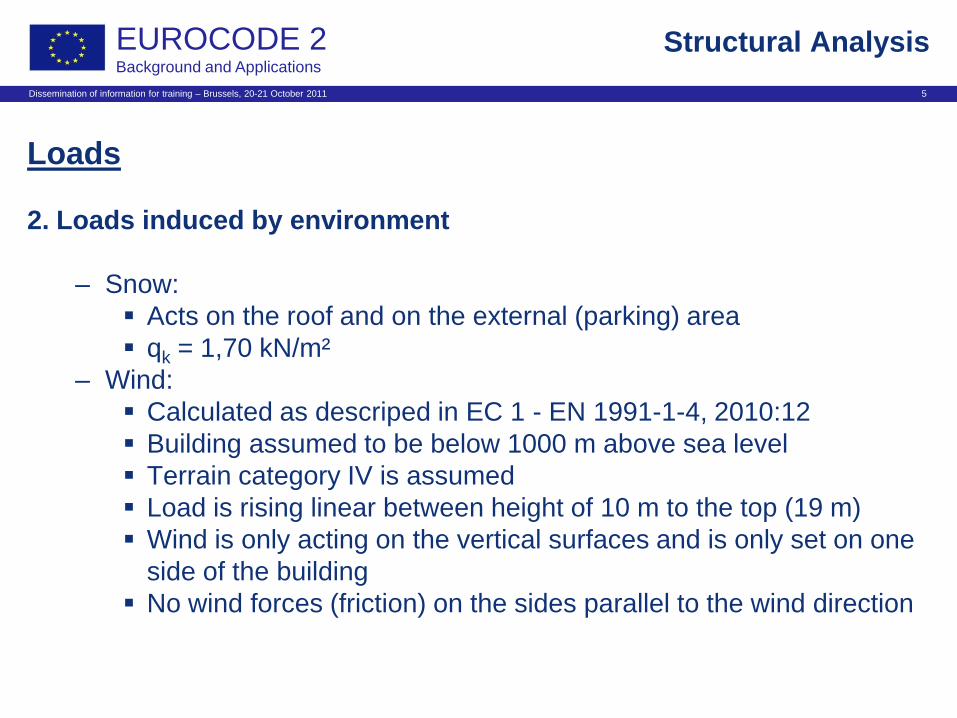
2. Loads induced by environment
– Snow:
Acts on the roof and on the external (parking) area
qk = 1,70 kN/m²
– Wind:
Calculated as descriped in EC 1 - EN 1991-1-4, 2010:12
Building assumed to be below 1000 m above sea level
Terrain category IV is assumed
Load is rising linear between height of 10 m to the top (19 m)
Wind is only acting on the vertical surfaces and is only set on one
side of the building
No wind forces (friction) on the sides parallel to the wind direction
Structural Analysis

Dissemination of information for training – Brussels, 20-21 October 2011 6
EUROCODE 2 Background and Applications
Structural Analysis
Loads
2. Loads induced by environment
–Calculation of the wind loads:
Facade acts as 2-span-girder in global X-direction of FEM-model
9,1 8,31 7,53 6,74 Middle support
2,73 2,49 2,26 2,02 End support
5th level 4th level 3rd level Support
h > 10 m h < 10 m Wind loads [kN/m]

Dissemination of information for training – Brussels, 20-21 October 2011 7
EUROCODE 2 Background and Applications
Structural Analysis
Loads
2. Loads induced by environment
–Calculation of the wind loads:
Facade acts as 5-span-girder in global Y-direction of FEM-model
6,08 5,55 5,03 4,5 2. Internal support
7,06 6,45 5,84 5,23 1. Internal support
2,46 2,25 2,04 1,82 End support
5th level 4th level 3rd level Support
h > 10 m h < 10 m Wind loads [kN/m]

Dissemination of information for training – Brussels, 20-21 October 2011 8
EUROCODE 2 Background and Applications
Loads
3. Loads caused by the use
– Dwelling (apartments, living):
Level 1 to 5, and roof (as service load)
qk = 2,00 kN/m²
– Public areas
Ground level, offices, Stairs
qk = 4,00 kN/m²
– Parking:
Levels below ground, external parking area
qk = 2,50 kN/m²
Structural Analysis

Dissemination of information for training – Brussels, 20-21 October 2011 9
EUROCODE 2 Background and Applications
0,7 0,6 2.50 kN/m² parking (level -1, -2,
external area)
Service load 2
0,7 0,3 2.00 kN/m²
4.00 kN/m²
dwelling (level 1-6)
stairs, office (level 0)
Service load 1
0,5 0 1.70 kN/m² snow on roof or
external area
Environmental load 2
0,6 0 0.77 kN/m² below
10 m
1.09 kN/m² at 19 m
wind Environmental load 1
- Variable
values
3.0 kN/m²
8.0 kN/m
dead load of
construction
dead load of interior
dead load of facade
Dead load
Combination factors
Ψ0 Ψ2 Value of load Load name Type of Exposure
Structural Analysis

Dissemination of information for training – Brussels, 20-21 October 2011 10
EUROCODE 2 Background and Applications
Finite Element Model
Type „Flat slab“
Structural Analysis

Dissemination of information for training – Brussels, 20-21 October 2011 11
EUROCODE 2 Background and Applications
Finite Element Model
Type „Beam slab“
Structural Analysis

Dissemination of information for training – Brussels, 20-21 October 2011 12
EUROCODE 2 Background and Applications
Finite Element Model
Type „Italian slab“
Structural Analysis

Dissemination of information for training – Brussels, 20-21 October 2011 13
EUROCODE 2 Background and Applications
Finite Element Model
Modeling:
– Slabs are modeled as plate elements
– Columns and outer shear walls are representet by rod elements
– Shear walls in the center of the building are modeled as plate
elements
– Beams for type „2-way slab with beams“ and type „slab with
embedded elements“ are modeled as plate elements and as rod
elements (combined)
– Rod elements provide easier evaluation
Structural Analysis

Dissemination of information for training – Brussels, 20-21 October 2011 14
EUROCODE 2 Background and Applications
Load Cases
1. Load Case 1 – Dead load of the construction – Calculated by SOFiSTiK
– For better overview only a single level is shown:
Structural Analysis
Area load from slab
Line load from inner column
Line load from shear wall
Line load from outer column
Cutout for stairs and
elevator

Dissemination of information for training – Brussels, 20-21 October 2011 15
EUROCODE 2 Background and Applications
Load Cases
2. Load Case 2 – Dead load of the interior – For better overview only the roof is shown:
Structural Analysis
Dissemination of information for training – Brussels, 20-21 October 2011 16
EUROCODE 2 Background and Applications
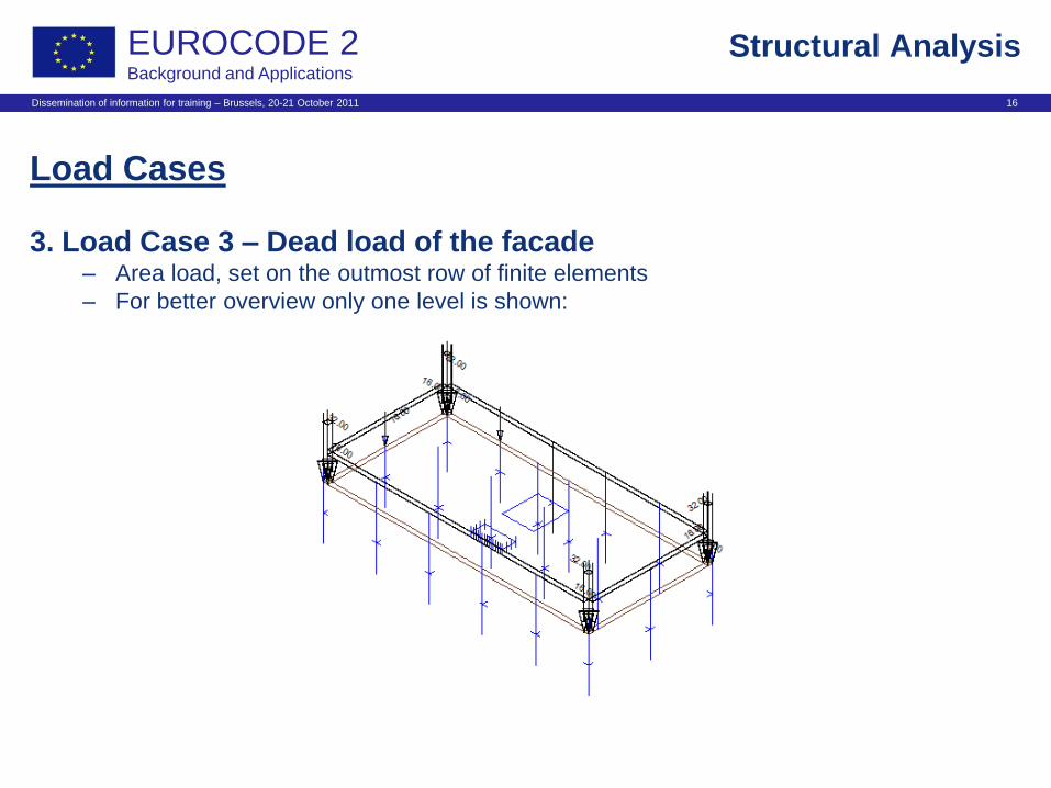
Load Cases
3. Load Case 3 – Dead load of the facade – Area load, set on the outmost row of finite elements
– For better overview only one level is shown:
Structural Analysis

Dissemination of information for training – Brussels, 20-21 October 2011 17
EUROCODE 2 Background and Applications
Load Cases
4. Load Case 51 – Wind in global X - direction – Facade acts as a 2-span-girder between columns
Structural Analysis

Dissemination of information for training – Brussels, 20-21 October 2011 18
EUROCODE 2 Background and Applications
Load Cases
5. Load Case 101 – Wind in global Y - direction – Facade acts as a 5-span-girder between columns
Structural Analysis

Dissemination of information for training – Brussels, 20-21 October 2011 19
EUROCODE 2 Background and Applications
Load Cases
6. Load Case 201 – Snow on roof
Structural Analysis

Dissemination of information for training – Brussels, 20-21 October 2011 20
EUROCODE 2 Background and Applications
Load Cases
7. Load Case 202 – Snow on external parking area – Load cases 203 to 206 with load in the next fields
Structural Analysis

Dissemination of information for training – Brussels, 20-21 October 2011 21
EUROCODE 2 Background and Applications
Structural Analysis
B2
Load Cases
8. Load Case 1326 – Service load on the roof
– For max. normal force in column B2

Dissemination of information for training – Brussels, 20-21 October 2011 22
EUROCODE 2 Background and Applications
Load Cases
9. Load Case 1356 – Service load on the roof
– For bi-axial bending of column B2
Structural Analysis
B2

Dissemination of information for training – Brussels, 20-21 October 2011 23
EUROCODE 2 Background and Applications
Load Cases
9. Load Case 10001 – Service load
– For bi-axial bending of column B2
– Only 2 levels shown
Structural Analysis
B2

Dissemination of information for training – Brussels, 20-21 October 2011 24
EUROCODE 2 Background and Applications
Load Cases
9. Load Case 10011 – Service load
– For uni-axial bending & for max. field moments in the beams (axis B)
– Only 2 levels shown
Structural Analysis

Dissemination of information for training – Brussels, 20-21 October 2011 25
EUROCODE 2 Background and Applications
Load Cases
9. Load Case 10021 – Service load
– For max. normal force in column B2
– Only 2 levels shown
Structural Analysis
B2

Dissemination of information for training – Brussels, 20-21 October 2011 26
EUROCODE 2 Background and Applications
Structural Analysis
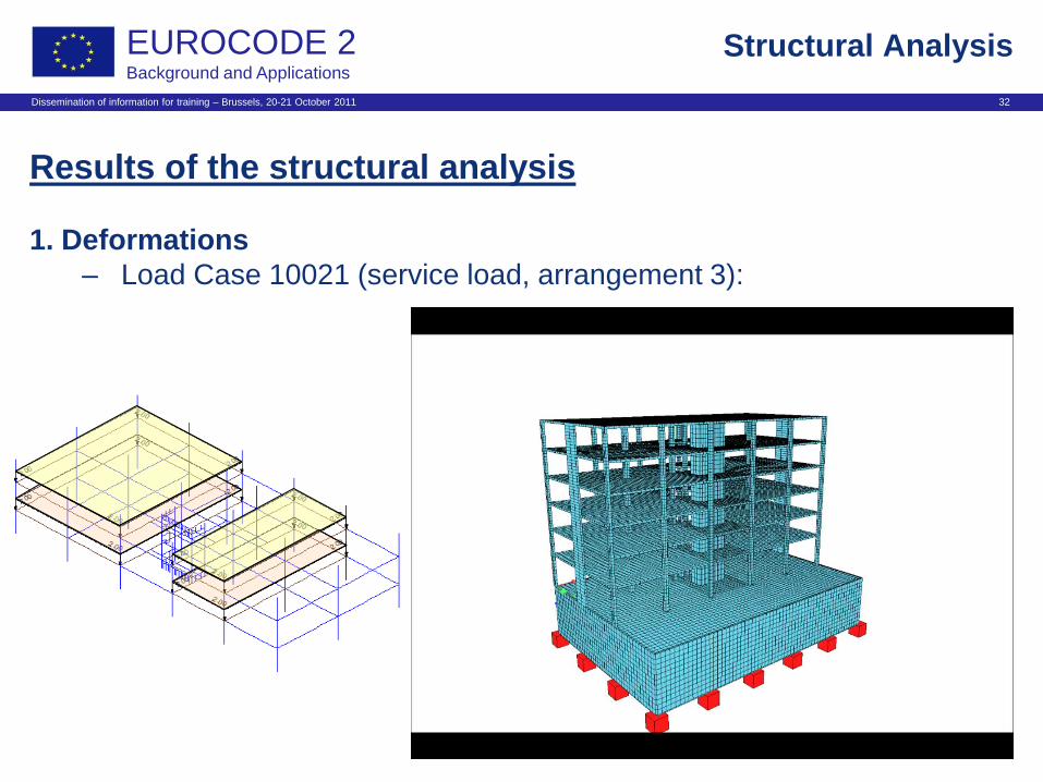
Results of the structural analysis
1. Deformations
– Load Case 1 (dead load):

Dissemination of information for training – Brussels, 20-21 October 2011 27
EUROCODE 2 Background and Applications
Structural Analysis
Results of the structural analysis
1. Deformations
– Load Case 3 (facade):

Dissemination of information for training – Brussels, 20-21 October 2011 28
EUROCODE 2 Background and Applications
Structural Analysis
Results of the structural analysis
1. Deformations
– Load Case 51 (wind in global X):

Dissemination of information for training – Brussels, 20-21 October 2011 29
EUROCODE 2 Background and Applications
Structural Analysis
Results of the structural analysis
1. Deformations
– Load Case 101 (wind in global Y):

Dissemination of information for training – Brussels, 20-21 October 2011 30
EUROCODE 2 Background and Applications
Structural Analysis
Results of the structural analysis
1. Deformations
– Load Case 10001 (service load, arrangement 1):

Dissemination of information for training – Brussels, 20-21 October 2011 31
EUROCODE 2 Background and Applications
Structural Analysis
Results of the structural analysis
1. Deformations
– Load Case 10011 (service load, arrangement 2):
Dissemination of information for training – Brussels, 20-21 October 2011 32
EUROCODE 2 Background and Applications
Structural Analysis
Results of the structural analysis
1. Deformations
– Load Case 10021 (service load, arrangement 3):

Dissemination of information for training – Brussels, 20-21 October 2011 33
EUROCODE 2 Background and Applications
Results of the structural analysis
Provided Data:
– Punching forces for slab design for type „Flat slab“ at the columns A1
and B2 in dwelling level
– Internal moments and shear forces for the 2-span-beam in axis 2
(2-way slab on beams) for ultimate limit state
– Internal moments and shear forces for the 5-span-beam in axis B
(slab with embedded elements) for ultimate limit state
– Internal moments and shear forces for the design of column B2 and
shear wall B1 for ultimate and serviceability limit state
– Bearing reactions for the design of the foundation of column B2 for
ultimate and serviceability limit state
Structural Analysis

Dissemination of information for training – Brussels, 20-21 October 2011 34
EUROCODE 2 Background and Applications
Structural Analysis
Results of the structural analysis
2. Punching
– Difference in normal force in the columns equals punching force
A1 B2
Normal force N
in [kN] E.g. load case 3 (facade):
For A1: ΔN = 179.02 – 134.18 = 44,84 KN
For B2: ΔN = 57,48 – 44,37 = 13,11 KN
A1
B2

Dissemination of information for training – Brussels, 20-21 October 2011 35
EUROCODE 2 Background and Applications
Structural Analysis
Results of the structural analysis
2. Punching
– This leads to the following table for all (authoritative) load cases:
Load Case A1: VEd [kN] B2: VEd [kN]
Dead load of construction 43,03 245,78
Dead load of interior 24,57 146,18
Dead load of facade 44,84 13,11
Service load, arrangement 1 -2,10 49,10
Service load, arrangement 2 -1,14 46,39
Service load, arrangement 3 16,39 97,23
Service load, arrangement 4 16,37 97,40

Dissemination of information for training – Brussels, 20-21 October 2011 36
EUROCODE 2 Background and Applications
Structural Analysis
Results of the structural analysis
2. Punching
– And leads to the following desing values by superposition:
Flat slab at column A1 VEd = 176,48 kN
Flat slab at column B2 VEd = 693,02 kN
A1 B2

Dissemination of information for training – Brussels, 20-21 October 2011 37
EUROCODE 2 Background and Applications
Structural Analysis
Results of the structural analysis
3. Internal forces and moments for beams in Axis 2, respectively B
– E.g. Load Case 1:
Int. moment My
in [kNm]
Calculation of frame
For 2-way slab with beams, 2 spans
(axis 2)
For slab with embedded elements,
first 3 of 5 spans shown (axis B)
-42,55
31,26
-27,70
-65,19
47,81
-72,13 -88,98
42,42

Dissemination of information for training – Brussels, 20-21 October 2011 38
EUROCODE 2 Background and Applications
Structural Analysis
Results of the structural analysis
3. Internal forces and moments for beams in Axis 2, respectively B
– Automatic superposition gives results for moments and shear forces:
Maximum shear force at all supports
Minimum moments at all supports
Maximum moments in span 1 (and in span 2 for slab with
embedded elements)
Minimum moments in spans 2 and 3 for slab with embedded
elements

Dissemination of information for training – Brussels, 20-21 October 2011 39
EUROCODE 2 Background and Applications
Structural Analysis
Results of the structural analysis
3. Internal forces and moments for column B2 and shear wall B1
Shear wall B1
Column B2

Dissemination of information for training – Brussels, 20-21 October 2011 40
EUROCODE 2 Background and Applications
Structural Analysis
Results of the structural analysis
3. Internal forces and moments for column B2 and shear wall B1
– Calculated analogous to the beams
– Superposition for the following values:
Max. and min. shear force in both local directions
Max. and min. internal moment in both local directions
Max. and min. normal force
– Calculated for the bottom end of column B2 in the 2nd level below
ground
– also the values that belong to these superpositions have been
calculated for the top end of this column
– Shear wall B1 is calculated in ground level

Dissemination of information for training – Brussels, 20-21 October 2011 41
EUROCODE 2 Background and Applications
Structural Analysis
Results of the structural analysis
3. Internal forces and moments for column B2 and shear wall B1
– e.g. for column B2 bottom end, ultimate limit state:
201, 10121 10031 &
1336
-4,49 -2,36 1,54 -4,53 -5697,49 min N
202 – 206, 10111 101 -0,29 4,20 -4,05 0,25 -4467,29 min Vz
201, 202, 1356, 10021 10121 -4,70 -2,09 -1,46 -4,81 -5358,27 min Vy
101, 201, 202, 1326, 10021 10121 -4,85 1,17 -1,43 -4,65 -5407,83 min Mz
201, 1326, 10031, 10101 51 -2,12 -3,64 2,96 -2,48 -5300,62 min My
202 – 205 51 -1,38 -2,73 2,27 -1,83 -4408,94 max N
10031, 10101 51 -2,08 -3,26 2,96 -2,46 -5139,33 max Vz
max Vy
51, 203- 206, 10011 10111 4,45 -2,43 1,88 4,46 -4827,82 max Mz
203 - 206, 1356, 10111 101 -0,31 4,21 -4,05 0,23 -4517,82 max My
Qi Q1 [kNm] [kNm] [kN] [kN] [kN]
Considered load cases Mz,d My,d Vz,d Vy,d Nd Superposition
51, 203- 206, 10011 10111 4,45 -2,43 1,88 4,46 -4827,82

Dissemination of information for training – Brussels, 20-21 October 2011 42
EUROCODE 2 Background and Applications
Structural Analysis
Summary of Structural Analysis
• Full results can be found in the workshop report
• Some additional data, which are
not in the report, were provided
for the detailing

Dissemination of information for training – Brussels, 20-21 October 2011 43
EUROCODE 2 Background and Applications
Structural Analysis
fin
Numerobis from Astérix le Gaulois
©www.comedix.de