Embed Size (px)
Citation preview

Dept. of Civil and Environmental Eng., SNU
Structural Analysis Lab. Prof. Hae Sung Lee, http://strana.snu.ac.kr
Structural Analysis I
Spring Semester, 2018
Hae Sung Lee
Dept. of Civil and Environmental Engineering Seoul National University
yδ
yf
zδ zf
xδ
xf
yM y
θ
zM z
θ x
M xθ

Dept. of Civil and Environmental Eng., SNU
Structural Analysis Lab. Prof. Hae Sung Lee, http://strana.snu.ac.kr
This page is intentionally left blank.

Dept. of Civil and Environmental Eng., SNU
Structural Analysis Lab. Prof. Hae Sung Lee, http://strana.snu.ac.kr
Contents
1. Introduction
2. Reactions & Internal Forces by Free Body Diagra
ms
3. Principle of Virtual Work
4. Analysis of Statically Indeterminate Beams
5. Analysis of Statically Indeterminate Trusses
6. Analysis of Statically Indeterminate Frames
7. Influence Lines for Determinate Structures
8. Influence Lines for Indeterminate Structures
Dept. of Civil and Environmental Eng., SNU
Structural Analysis Lab. Prof. Hae Sung Lee, http://strana.snu.ac.kr
This page is intentionally left blank.
Dept. of Civil and Environmental Eng., SNU
Structural Analysis Lab. Prof. Hae Sung Lee, http://strana.snu.ac.kr
1
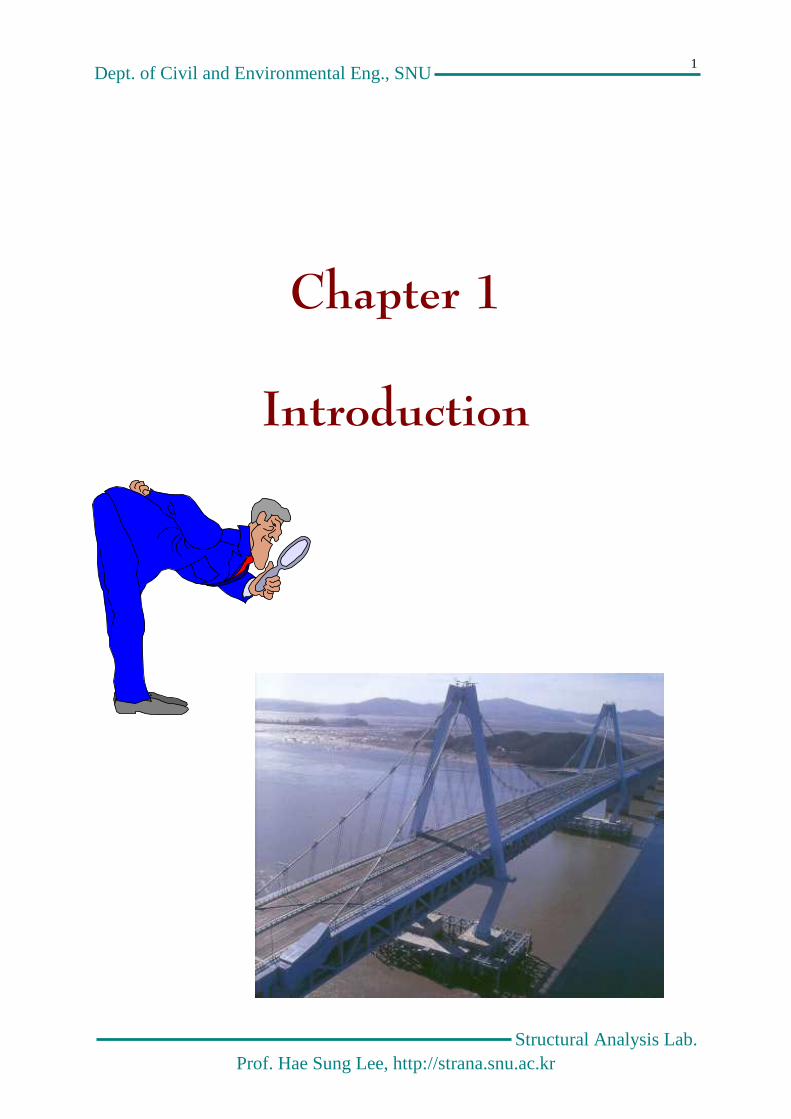
Chapter 1
Introduction
Dept. of Civil and Environmental Eng., SNU
Structural Analysis Lab. Prof. Hae Sung Lee, http://strana.snu.ac.kr
2
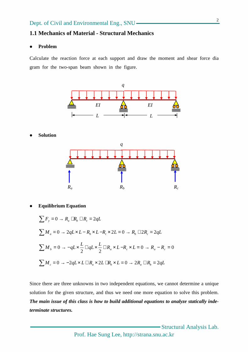
1.1 Mechanics of Material - Structural Mechanics
Problem
Calculate the reaction force at each support and draw the moment and shear force dia
gram for the two-span beam shown in the figure.
Solution
Equilibrium Equation
qLRRRF cbay 20 =++→=
qLRRLRLRLqLM cbcba 220220 =+→=×−×−×→=
0022
0 =−→=×−×+×+×−→= cacab RRLRLRL
qLL
qLM
qLRRLRLRLqLM babac 220220 =+→=×+×+×−→=
Since there are three unknowns in two independent equations, we cannot determine a unique
solution for the given structure, and thus we need one more equation to solve this problem.
The main issue of this class is how to build additional equations to analyze statically inde-
terminate structures.
EI EI
q
Ra Rb Rc
L L
q

Dept. of Civil and Environmental Eng., SNU
Structural Analysis Lab. Prof. Hae Sung Lee, http://strana.snu.ac.kr
3
Fundamentals of Differential Equations
Governing Equations
The governing equations of a (engineering) system are usually defined by a system of diffe-
rential equations, which governs behaviors of the given system within a domain. Notice that
the domain does not include boundaries.
11 qwEI =′′′′ for lx <<0
Boundary Condition
– Suppose you have an n-th order differential equation, then n boundary conditions
should be specified to determine a unique solution because there exist n integration
constants in the general solution of your differential equation(s).
– The boundary conditions are specified with up to (n-1)-th derivatives of the unknown
functions.
w , w′ , w ′′ (Moment), w ′′′ (shear Force)
– The same number of the boundary conditions should be specified at each boundary for
structural problems, which means that the governing equation of a structural problem
should an even order differential equation.
– Only half of n-possible boundary conditions is specified at each boundary, and the
other half is unknown, and should be calculated through the structural analysis.
– The derivatives of the unknown function lower than n/2 order is called “displace-
ment” and the derivatives of the unknown function equal to or higher than n/2 order
represent force terms in your structural system
– How to Determine Integration Constants in the General Solution of the given D.E.???
EI
l
q

Dept. of Civil and Environmental Eng., SNU
Structural Analysis Lab. Prof. Hae Sung Lee, http://strana.snu.ac.kr
4
1.2 Mechanics of Material
Governing Equation
– Left span
112
13
1
4
1''''
1 24dxcxbxa
EI
qxwqEIw ++++=→=
– Right Span
222
23
2
4
2''''
2 24dxcxbxa
EI
qxwqEIw ++++=→=
Boundary Conditions
– Left support
0)0()0( , 0)0( 111 =′′−== wEIMw
– Center support
)()( , )()( , 0)()( 212121 LwLwLwLwLwLw ′′=′′′−=′==
– Right support
0)0()0( , 0)0( 222 =′′−== wEIMw
Since there are eight unknowns with eight conditions, we can solve this problem.
Determination of Integration Constant – Left Support
xcxaEI
qxwbwdw 1
31
4
11111 2402)0( , 0)0( ++=→==′′==
– Right Support
xcxaEI
qxwbwdw 2
32
4
22222 2402)0( , 0)0( ++=→==′′==
x x
y
z
z
y
q
w1 w2

Dept. of Civil and Environmental Eng., SNU
Structural Analysis Lab. Prof. Hae Sung Lee, http://strana.snu.ac.kr
5
– Center Support
==
−==→
+=+
−−−=++
=++=
=++=
EI
qLcc
EI
qLaa
LaEI
qLLa
EI
qL
cLaEI
qLcLa
EI
qL
LcLaEI
qLLw
LcLaEI
qLLw
48
48
3
62
62
36
36
024
)(
024
)(
3
21
21
2
2
1
2
22
2
3
12
1
3
23
2
4
2
13
1
4
1
)32(48
33421 xLLxx
EI
qww +−=≡
83
, 8
32 11
211
qLqxwEIVx
qLx
qwEIM +−=′′′−=+−=′′−=
Moment Diagram
Shear Diagram
Reactions
0.375qL
L83
+
-
+
0.625qL
-
0.375qL 0.375qL 1.25qL
0.125qL2
0.070qL2
L8
3
+
-
+

Dept. of Civil and Environmental Eng., SNU
Structural Analysis Lab. Prof. Hae Sung Lee, http://strana.snu.ac.kr
6
1.3 Mechanics of Material + α
1.3.1 Main idea
Original Problem
Case I (Removal of the center support)
Case II (Application of the reaction force)
Original Problem = Case I + Case II (compatibility condition)
δ0+ δR=0
1.3.2 Calculation of δ0
Bending Moment
qLxqx
M +−=2
2
q
q
δ0
δR
Rb
q
qL2/2
Dept. of Civil and Environmental Eng., SNU
Structural Analysis Lab. Prof. Hae Sung Lee, http://strana.snu.ac.kr
7
Governing Equation
baxqLxqx
EIwMwEI ++−=→−=′′624
34
00
Boundary (support) Conditions
– Left Support : 0)0(0 =w
– Right Support : 0)2(0 =Lw
Determination of Integration Constant
– Left Support
0 0)0(0 =→= bEIw
– Right Support
EI
LqaLa
LqLqLEIw
24
)2(0)2(
6
)2(
24
)2()2(
334
0 =→=+−=
Deflection
))2()2(2(24
3340 LxLxx
EI
qw +−=
EI
LqLLLLL
EI
qLw
384)2(5
))2()2(2(24
)(4
33400 =+−==δ
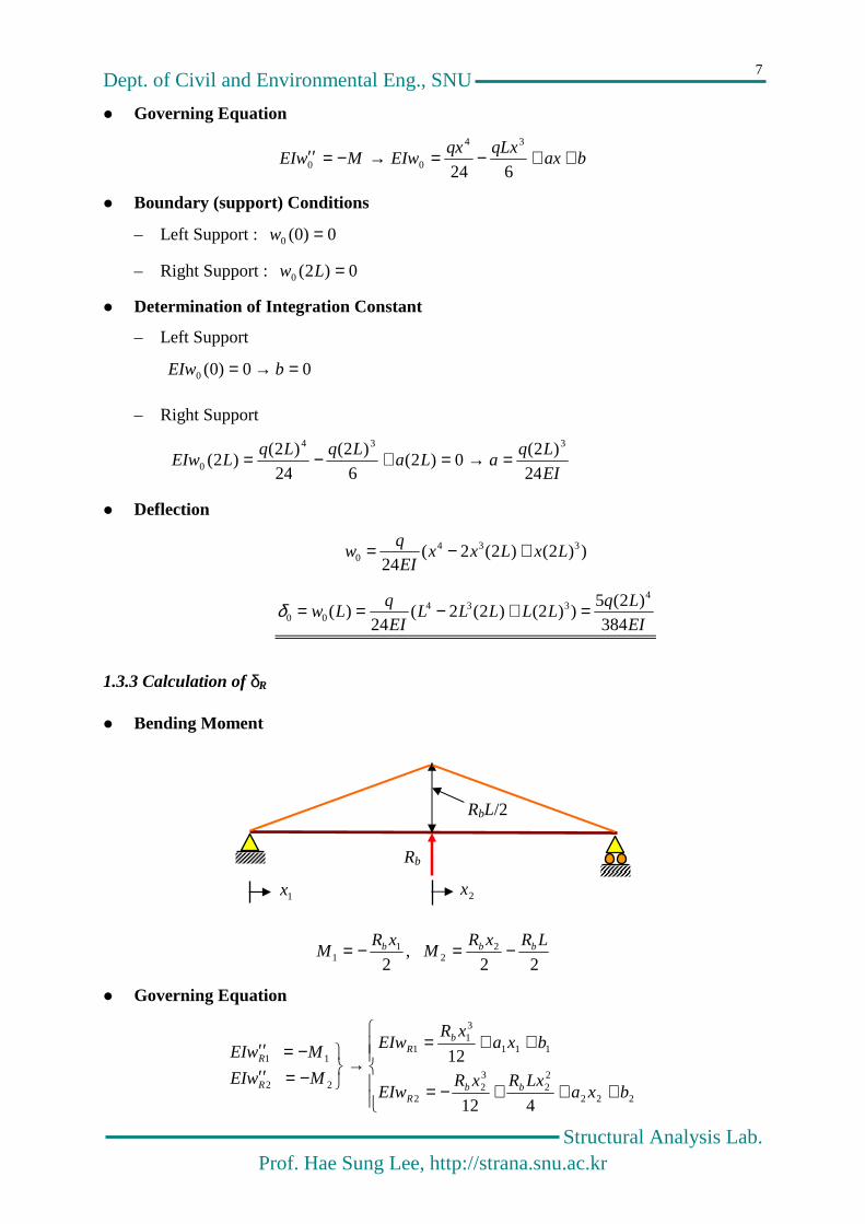
1.3.3 Calculation of δR
Bending Moment
22,
22
21
1
LRxRM
xRM bbb −=−=
Governing Equation
+++−=
++=→
−=′′−=′′
222
22
32
2
111
31
1
22
11
412
12
bxaLxRxR
EIw
bxaxR
EIw
MwEI
MwEI
bbR
bR
R
R
1x 2x
RbL/2
Rb

Dept. of Civil and Environmental Eng., SNU
Structural Analysis Lab. Prof. Hae Sung Lee, http://strana.snu.ac.kr
8
Boundary (support and mid-span) Conditions
– Left Support & Right Support
0)( , 0)0( 21 == Lww RR
– Mid-span
)( )0()()( , )0()( 221121 LwLwLwLw RRRRRR θ=′=′=θ=
Determination of Integration Constant
– Left Support
0 0)0( 11 =→= bwR
– Right Support & Mid-span
−=
=
−=
→
′==+=′
==+=
=+++−=
6
04
(0)4
)(
(0)12
)(
0412
)(
3
2
2
2
1
221
2
1
221
3
1
22
33
2
LRb
a
LRa
wEIaaLR
LwEI
EIwbLaLR
LEIw
bLaLRLR
LEIw
b
b
Rb
R
Rb
R
bbR
Deflection
)23(12
)3(12
322
322
123
11
LLxxEI
Rw
xLxEI
Rw
bR
bR
+−−=
−=
EI
RLwLw b
RRR 48
)2()0()(
3
21 −===δ
Compatibility Condition
δ0+ δR=0 → 048
)2(
384
)2(5 34
=−EI
RL
EI
Lq b → qLRb 8
10=

Dept. of Civil and Environmental Eng., SNU
Structural Analysis Lab. Prof. Hae Sung Lee, http://strana.snu.ac.kr
9
1.4 Structural Mechanics
Original Problem
Case I (Removal of the center support)
Case II (Application of the reaction force)
Original Problem = Case I + Case II
δ0+ δR=0
Principle of Virtual Work
EI
Lqdx
EI
MMLR
384)2(5 42
0
00 −== δ ,
EI
LRdx
EI
MM bL
RRR 48
)2( 32
0
== δ
Solution
δ0+ δR=0 → 048
)2(384
)2(5 34
=+−EI
RL
EI
Lq b → qLRb 8
10=
RbL/2
Rb
q
q
qL2/2

Dept. of Civil and Environmental Eng., SNU
Structural Analysis Lab. Prof. Hae Sung Lee, http://strana.snu.ac.kr
10
– Moment
– Shear
+
-
+
-
+
+ -
+
-
=
0.070qL2
5qL2/8
Rb
+
=
0.125qL2 L
8
3
+
-
+
qL2/2
Dept. of Civil and Environmental Eng., SNU
Structural Analysis Lab. Prof. Hae Sung Lee, http://strana.snu.ac.kr
11
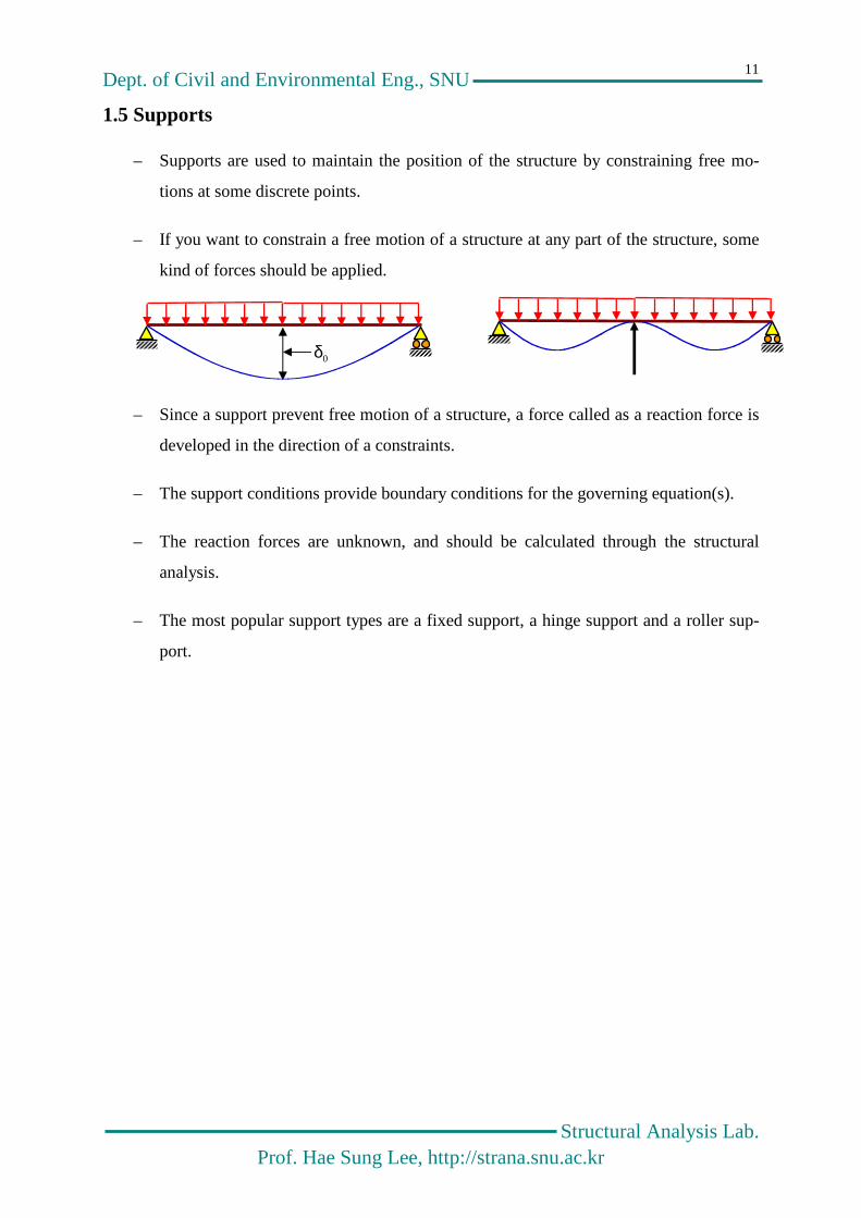
1.5 Supports
– Supports are used to maintain the position of the structure by constraining free mo-
tions at some discrete points.
– If you want to constrain a free motion of a structure at any part of the structure, some
kind of forces should be applied.
– Since a support prevent free motion of a structure, a force called as a reaction force is
developed in the direction of a constraints.
– The support conditions provide boundary conditions for the governing equation(s).
– The reaction forces are unknown, and should be calculated through the structural
analysis.
– The most popular support types are a fixed support, a hinge support and a roller sup-
port.
δ0δ

Dept. of Civil and Environmental Eng., SNU
Structural Analysis Lab. Prof. Hae Sung Lee, http://strana.snu.ac.kr
12
Fixed Support(고정단)
– Both the horizontal and vertical motion and rotational motion are prevented.
– Reaction forces are developed in three directions.

Dept. of Civil and Environmental Eng., SNU
Structural Analysis Lab. Prof. Hae Sung Lee, http://strana.snu.ac.kr
13
Hinged Support(회전단)
– The horizontal and vertical motion are prevented, but the rotational motion is allowed.
– The horizontal and vertical reaction forces are developed in all three directions
Roller Support(이동단)
– Only the vertical motion is prevented, and the horizontal and the rotational motion is
allowed.
– A reaction force is developed only in the vertical direction.

Dept. of Civil and Environmental Eng., SNU
Structural Analysis Lab. Prof. Hae Sung Lee, http://strana.snu.ac.kr
14
1.6 Two-Dimensional Idealization of a Structure
Real 3-D Structures
– 3 force components and 3 moment components
– 3 displacement components and 3 rotational components
Main Structures : A part of a structure designed mainly to resist external loads.
– Beams, Truss, Frame, Arch…
Secondary Structure : A part of a structure designed to transfer external loads to
main structures or increase stability and/or stiffness of a structure
– Stringer : Small beam that runs parallel to a main structure to support the floor
system.
– Cross beam : Small beam that runs perpendicular to the main structure to support
stringers.
– Bracing (tie) : member that connects two or more main structures to increase mainly
lateral stability of the main structures.
xδ xf
ym yθ zδ
x
y
z
yδ yf
zδ zf
xδ xf ym yθ
zm zθ xm xθ

Dept. of Civil and Environmental Eng., SNU
Structural Analysis Lab. Prof. Hae Sung Lee, http://strana.snu.ac.kr
15
Load transfer path
External load → Slab → Stringer → Cross Beam → Main Structure → Support →
Foundation
– External loads applied on a slab are supported by stringers, which transfer the carried
loads to cross beams. The cross beams, in turn, transfer the carried-over loads from
the stringers to main structures.
주 구조물 (Main Structure)
가로 보 (Cross Beam)
세로 보 (Stringer )
Cross Bracing (Wind Bracing)
지 점 (Support)

Dept. of Civil and Environmental Eng., SNU
Structural Analysis Lab. Prof. Hae Sung Lee, http://strana.snu.ac.kr
16
Two-dimensional Idealization of a Structures
All members are idealized as one-dimensional members, which are represented by
lines passing the centroids of the cross sections, because dimensions in cross-
sectional directions are very small compared to their lengths (usually less than 1/20).
Suppose we somehow know portions of the external loads transferred to each main
structure.
Suppose all members in each main structure lie in one plane, and external loads car-
ried-over from substructures are applied on the same planes.
Then, all structural responses are developed in the same plane, and main load resist-
ing actions occur in the same plane.
If this the case, each main structure in the same plane can be separated from the
whole structure by neglecting three-dimensional effects, and analyzed in the plane
where each main structure is defined for the simplicity of a structural analysis.
Two-dimensional structures are often referred to as plane structures.
However, fundamentals employed in the 2-D analysis of structures are exactly the
same as those in the 3-D analysis.
Dept. of Civil and Environmental Eng., SNU
Structural Analysis Lab. Prof. Hae Sung Lee, http://strana.snu.ac.kr
17
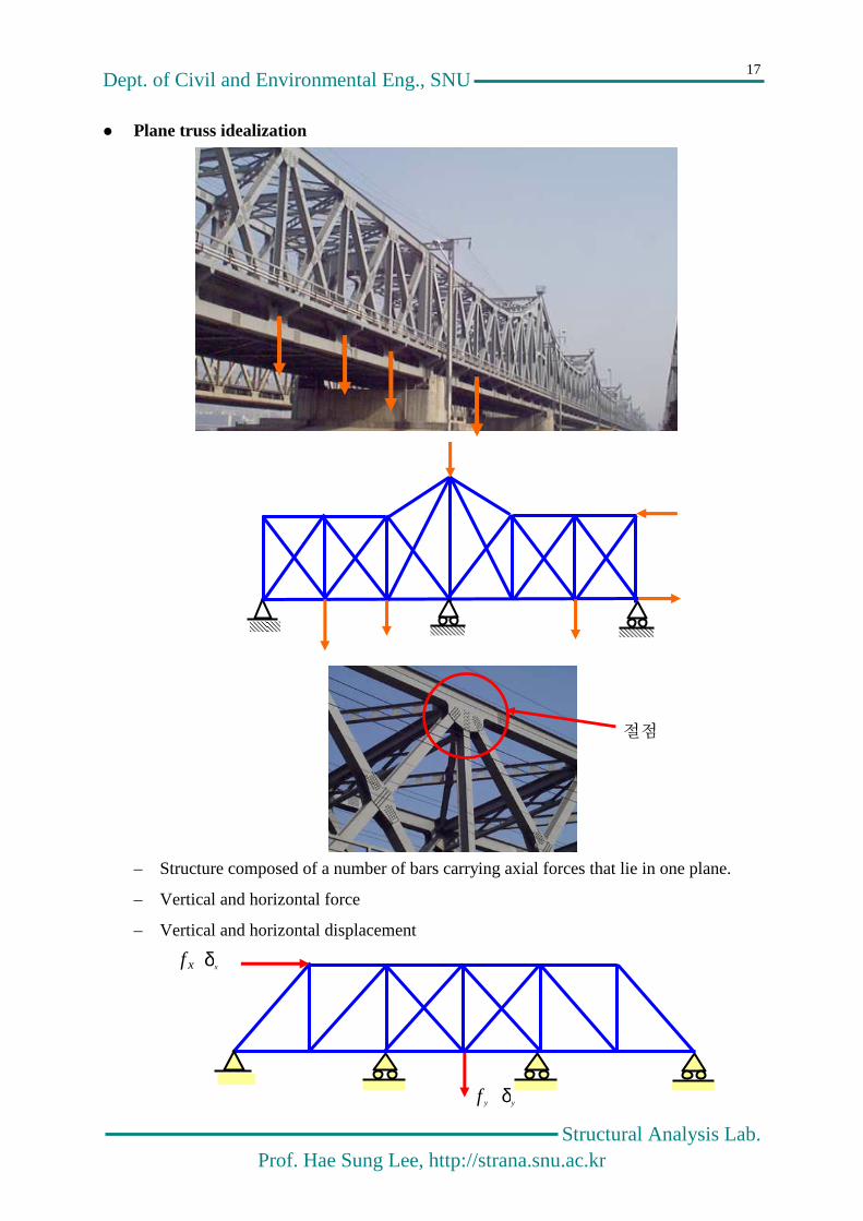
Plane truss idealization
– Structure composed of a number of bars carrying axial forces that lie in one plane.
– Vertical and horizontal force
– Vertical and horizontal displacement
절점
xf xδ
yδ yf

Dept. of Civil and Environmental Eng., SNU
Structural Analysis Lab. Prof. Hae Sung Lee, http://strana.snu.ac.kr
18
Plane beam idealization
– Structure composed of a number of beams carrying bending moments and shear
forces that lies in one plane.
– Shear force and Moment on z-axis
– Vertical displacement and rotational angle with respect to z-axis
11 , wV 22 , wV
33 , wV
11 , θM 22 , θM 33 , θM
Dept. of Civil and Environmental Eng., SNU
Structural Analysis Lab. Prof. Hae Sung Lee, http://strana.snu.ac.kr
19
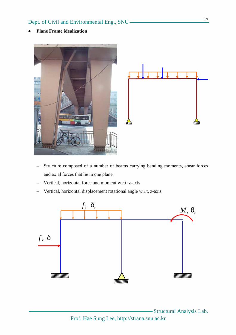
Plane Frame idealization
– Structure composed of a number of beams carrying bending moments, shear forces
and axial forces that lie in one plane.
– Vertical, horizontal force and moment w.r.t. z-axis
– Vertical, horizontal displacement rotational angle w.r.t. z-axis
xδ xf
yf yδ zM zθ
Dept. of Civil and Environmental Eng., SNU
Structural Analysis Lab. Prof. Hae Sung Lee, http://strana.snu.ac.kr
20
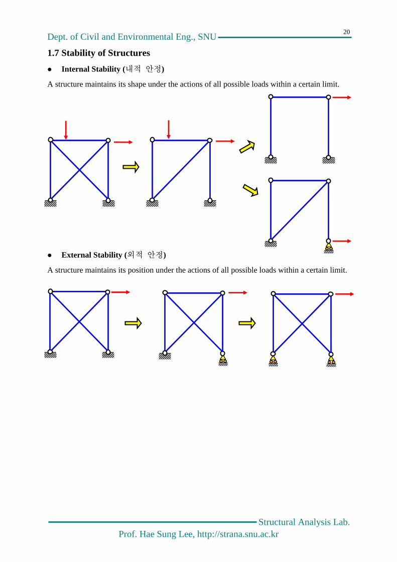
1.7 Stability of Structures
Internal Stability (내적 안정)
A structure maintains its shape under the actions of all possible loads within a certain limit.
External Stability (외적 안정)
A structure maintains its position under the actions of all possible loads within a certain limit.

Dept. of Civil and Environmental Eng., SNU
Structural Analysis Lab. Prof. Hae Sung Lee, http://strana.snu.ac.kr
21
This page is intentionally left blank.
Dept. of Civil and Environmental Eng., SNU
Structural Analysis Lab. Prof. Hae Sung Lee, http://strana.snu.ac.kr
22
Chapter 2
Reactions & Internal Forces
by Free Body Diagrams

Dept. of Civil and Environmental Eng., SNU
Structural Analysis Lab. Prof. Hae Sung Lee, http://strana.snu.ac.kr
23
2.1 Free Body Diagram
Any portion of a structure can be isolated by passing any desired section through structure.
A free body sketch is a diagram drawn showing this portion acted upon by the external loads
and reactions, together with any forces that may be act on the faces of the members cut by the
isolating section. Or, a diagram drawn by removing some part(s) of a structure and replacing
the removed part(s) with unknown forces.

Dept. of Civil and Environmental Eng., SNU
Structural Analysis Lab. Prof. Hae Sung Lee, http://strana.snu.ac.kr
24
It is impossible to draw too many free-body diagrams.
Time spent in doing so is never wasted
- C. H. Norris & J. B. Wilbur & S. Utku -
Dept. of Civil and Environmental Eng., SNU
Structural Analysis Lab. Prof. Hae Sung Lee, http://strana.snu.ac.kr
25
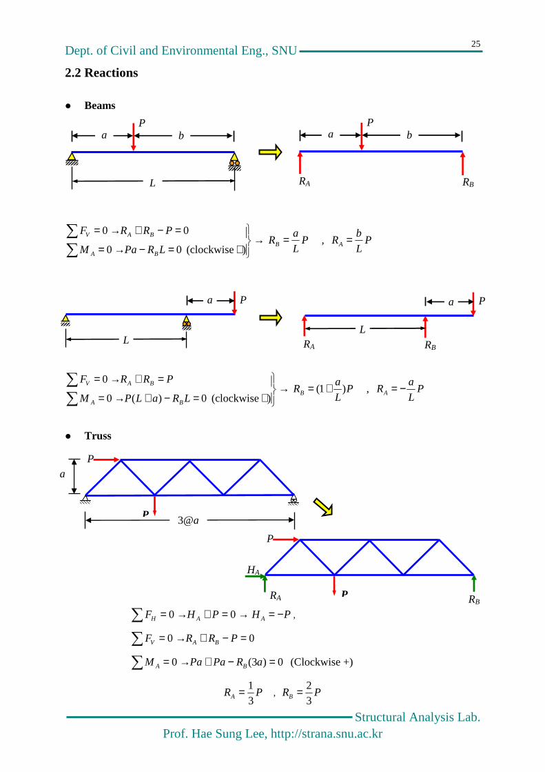
2.2 Reactions
Beams
→
+=−→=
=−+→=
) (clockwise 00
00
LRPaM
PRRF
BA
BAVP
L
aRB = , P
L
bRA =
→
+=−+→=
=+→=
) (clockwise 0)(0
0
LRaLPM
PRRF
BA
BAVP
L
aRB )1( += , P
L
aRA −=
Truss
PHPHF AAH −=→=+→= 00 ,
00 =−+→= PRRF BAV
0)3(0 =−+→= aRPaPaM BA (Clockwise +)
PRA 31= , PRB 3
2=
P
a b
L
P
RA
LRB
L
b a
P a
L
P a
L
RA
LRB
L
RA
LRB
P
P
HA
L
P
P
3@a
a
Dept. of Civil and Environmental Eng., SNU
Structural Analysis Lab. Prof. Hae Sung Lee, http://strana.snu.ac.kr
26
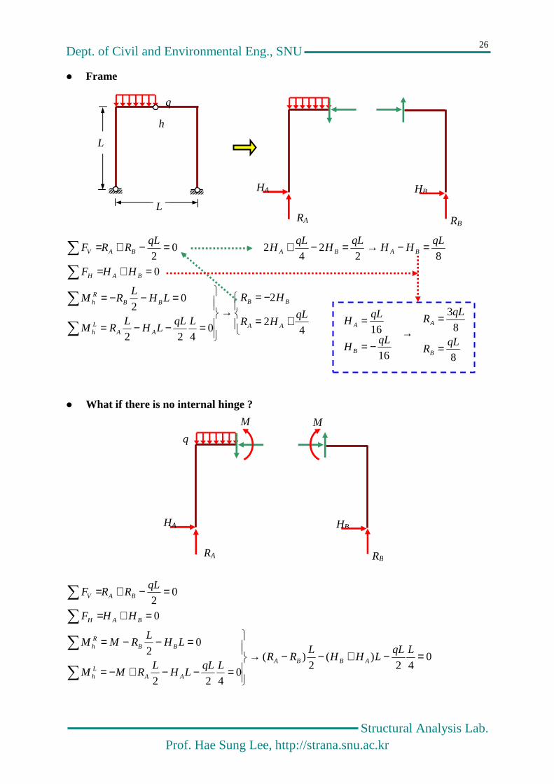
Frame
+=
−=→
=−−=
=−−=
=+=
=−→=−+=−+=
42
2
0422
02
082
24
2 02
qLHR
HR
LqLLH
LRM
LHL
RM
HHF
qLHH
qLH
qLH
qLRRF
AA
BB
AALh
BBRh
BAH
BABABAV
What if there is no internal hinge ?
042
)(2
)(
0422
02
0
02
=−+−−→
=−−+−=
=−−=
=+=
=−+=
LqLLHH
LRR
LqLLH
LRMM
LHL
RMM
HHF
qLRRF
ABBA
AALh
BBRh
BAH
BAV
HB
RA RB
HA
L
L
h
q
→−=
=
16
16qL
H
qLH
B
A
8
8
3
qLR
qLR
B
A
=
=
HB
RA RB
HA
q
M M

Dept. of Civil and Environmental Eng., SNU
Structural Analysis Lab. Prof. Hae Sung Lee, http://strana.snu.ac.kr
27
2.3 Internal Forces in Framed Structures
Axial Force
Shear Force
Bending Moment
Torsion
+
+
+
+

Dept. of Civil and Environmental Eng., SNU
Structural Analysis Lab. Prof. Hae Sung Lee, http://strana.snu.ac.kr
28
2.4 Internal Forces in Simple Beams
Reactions
q
RA=qL/2 Rb= qL/
q
RA=qL/2 RB= qL/2
RA RB

Dept. of Civil and Environmental Eng., SNU
Structural Analysis Lab. Prof. Hae Sung Lee, http://strana.snu.ac.kr
29
Free Body Diagram for Shear and Moment
qxqL
qxRVVqxRF AxxAV −=−=→=−−= 20
22
02
2qxx
qLMM
xqxxRM xxAx −=→=−−=
Differential Equation
baxxq
Mqdx
Md ++−=→−= 22
2
2
Boundary Conditions: 2
222,00)()0( x
qx
qLM
qLabLMM −=→==→==
Shear Force and Moment Diagrams
Deflected Shape
Remember 2
2
dx
wdEIM −= !!!
RA
x
RB
Mx
Vx
+
qL/2
qL2/8

Dept. of Civil and Environmental Eng., SNU
Structural Analysis Lab. Prof. Hae Sung Lee, http://strana.snu.ac.kr
30
2.5 Gerber Systems
A structural system that an unstable structural component is supported by a stable structure.
Sometimes there may be several unstable structures are supported by a stable structure, and
vice versa. An external load applied to an unstable structure is transferred to a stable struc-
ture, but an external load applied to a stable structure is not transferred to an unstable structure.
In the later case, a unstable structure is just deflected as a rigid body without deformation.

Dept. of Civil and Environmental Eng., SNU
Structural Analysis Lab. Prof. Hae Sung Lee, http://strana.snu.ac.kr
31

Dept. of Civil and Environmental Eng., SNU
Structural Analysis Lab. Prof. Hae Sung Lee, http://strana.snu.ac.kr
32
2.5.1 Internal Forces in a Gerber Beam - I
Reactions
PRL
PL
RM HHC 3
20
24
30 =→=×−×→=
PRPRRF CCHv 3
100 =→=−+→=
PRL
RLRM BHBA 6
50
4
50 =→=×+×−→=
PRPRRF ABAv 6
10
3
20 −=→=−+→=
L/4
P
RH
RA RB
RC
P
P/6 5P/6 P/3
P
Dept. of Civil and Environmental Eng., SNU
Structural Analysis Lab. Prof. Hae Sung Lee, http://strana.snu.ac.kr
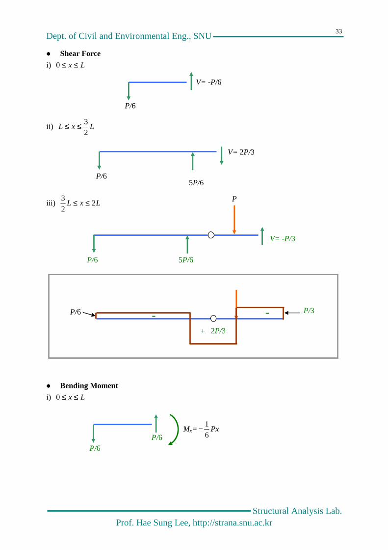
33
Shear Force
i) Lx ≤≤0
ii) LxL2
3≤≤
iii) LxL 22
3 ≤≤
Bending Moment
i) Lx ≤≤0
P/6
V= -P/6
P/6 5P/6
V= 2P/3
P/6 5P/6
P
V= -P/3
+
- -
2P/3
P/3 P/6
P/6
P/6 Mx= Px
6
1−
Dept. of Civil and Environmental Eng., SNU
Structural Analysis Lab. Prof. Hae Sung Lee, http://strana.snu.ac.kr
34
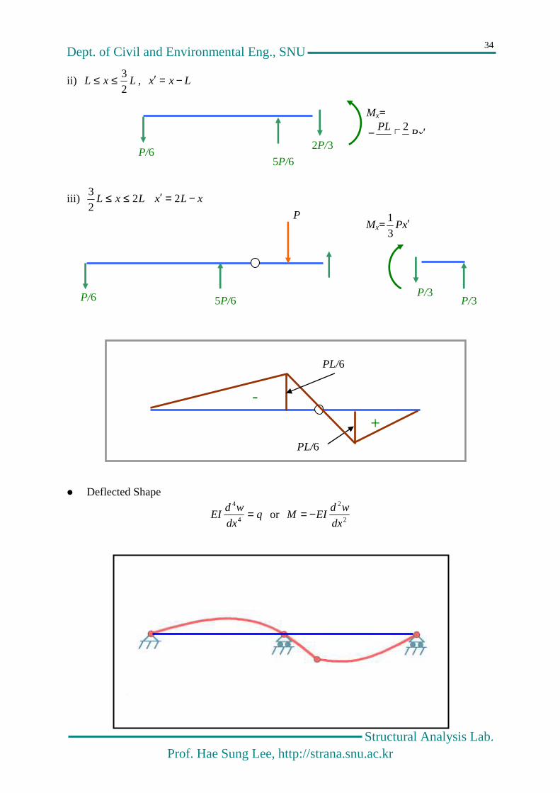
ii) LxL2
3≤≤ , Lxx −=′
iii) LxL 22
3 ≤≤ xLx −=′ 2
Deflected Shape
qdx
wdEI =
4
4
or 2
2
dx
wdEIM −=
P/6 5P/6
2P/3
Mx=
xPPL ′+− 2
P/6 5P/6
P
P/3 P/3
Mx= xP ′3
1
+
-
PL/6
PL/6

Dept. of Civil and Environmental Eng., SNU
Structural Analysis Lab. Prof. Hae Sung Lee, http://strana.snu.ac.kr
35
2.5.2 Internal Forces in a Gerber Beam - II
Free Body diagram
Shear
q
2
ql
2
ql
2
ql
2
ql
2
2ql
2
2ql
2
ql
2
ql
+
L
q
L L
2
ql
2
ql
x
qxql
Vx −=2
2
ql

Dept. of Civil and Environmental Eng., SNU
Structural Analysis Lab. Prof. Hae Sung Lee, http://strana.snu.ac.kr
36
Moment
Deflected Shape
8
2ql
2
2ql 2
2ql
+
xqlql
Mxqlql
M xx 220
22
22
+−=→=−+
2
ql
2
2ql
2
ql
x
2
ql
220
2
2qxx
qLMM
xqxxR xxA −=→=++−

Dept. of Civil and Environmental Eng., SNU
Structural Analysis Lab. Prof. Hae Sung Lee, http://strana.snu.ac.kr
37
2.6 Truss (트러스)
Structures composed of a number of straight bars carrying axial forces.

Dept. of Civil and Environmental Eng., SNU
Structural Analysis Lab. Prof. Hae Sung Lee, http://strana.snu.ac.kr
38
Assumption
1. All joints are hinges.
2. All members are straight.
3. Small deformatiom
4. The external loads are applied only at joints.
The 1st assumption seems to be unreasonable, but it is very reasonable assumption !!!
Because the length of each member is short compared to the total length of a truss, the mo-
ment induced by rigid joints is negligibly small in an engineering sense.
Characteristics of truss
– By the 2nd , 3rd and 4th assumptions
02
2
2
2
=→−=dx
Mdq
dx
Md→ baxM +=
– By the 1st assumption
0 , 000)()0( ≡≡→==→== VMbaLMM
– No bending moment and shear force are induced in all members in a truss structure.
– Only axial forces are the internal forces in a truss.
– The axial force is constant along a member by assumption 1.
– There is only one unknown per member.
– As the equilibirium of each member is always satisfied, the equilibrium conditions at
joints are to be considered.
– Determinancy
– The number of unknowns : RM NN +
– The number of Equilibrium Equations : JN2
– 02 =−+ JRM NNN : Determinant, 02 >−+ JRM NNN : Indeterminant

Dept. of Civil and Environmental Eng., SNU
Structural Analysis Lab. Prof. Hae Sung Lee, http://strana.snu.ac.kr
39
2.6.1 Internal Forces in Howe Truss
At U1 and U3
At L1
2 ,
22
022
2
02
2
23
3
23 PFPF
PF
FF=−=→
=+
=+
At L2
2 , 0- , 0 265625
PFFPFFFPF ===→=+=−
F1 F3
F2
P/2
F5
F2 F6
P
F4=0
F1=0
F8 =0
F9=0
9+3-2×6=0: determinant truss
L2
7
9 1
4
2
3
U1 U2 U3
6
5
L1
P/2 P/2
L3
8
P
2@a
a

Dept. of Civil and Environmental Eng., SNU
Structural Analysis Lab. Prof. Hae Sung Lee, http://strana.snu.ac.kr
40
At U2
=+−
−==→
=−−−
=++−−
02
1
2
12
2
02
2
2
2
02
2
2
237
753
8734
PPP
PFF
FFF
FFFF
At L3
Because we already have 3 equilibrium equations to calculate the reactions
Axial Force Diagram
2
P
2
P
F5
F4 F8
F3 F7
2
P 0
P/2
P/2
P/2 P/2
P 0
0 0
0
P P/2 P/2
Tension Compression

Dept. of Civil and Environmental Eng., SNU
Structural Analysis Lab. Prof. Hae Sung Lee, http://strana.snu.ac.kr
41
Equilvalent Beam Action
Axial forces in members generate bending moments and shear forces just like in a beam !!!
Deflected Shape
2.6.2 Internal Forces in Warren Truss
V=P/2
P/2
1 P
3P
32P
2 3
4
5
6
7
8
9
10
11
L1 L2 L3
U1 U2 U3
L4
x
PL/4 M=Px/2
3@2l
l

Dept. of Civil and Environmental Eng., SNU
Structural Analysis Lab. Prof. Hae Sung Lee, http://strana.snu.ac.kr
42
At L1
PFPFP
F
FF
32
, 322
03
222
022
12
2
12
=−=→
=+
=+
At U1
PFPFF
FF
FFF
34
,232
022
22
02
2
2
2
423
32
432
−==−=→
=+
=++−
At L2
PFPF
FFFF
PFF==→
=+−+
=−+65
5361
35
,32
022
22
-
022
22
F2
F1
2P/3
F4
F2 F3
F3
F1 F6
P
F5

Dept. of Civil and Environmental Eng., SNU
Structural Analysis Lab. Prof. Hae Sung Lee, http://strana.snu.ac.kr
43
At U2
PFPF
FF
FFFF
32
,32
022
22
02
2
2
2
87
75
7584
−=−=→
=−−
=+−+−
At L3
3,
32
022
22
022
22
109
97610
97 PFPF
FFFF
FF==→
=+−−
=+
At U3
PF
FF
FFF
32
022
22
022
22
11
119
8119
−=→
=−−
=−+−
F8
F5 F7
F4
F7
F6 F10
F9
F11
F8
F9

Dept. of Civil and Environmental Eng., SNU
Structural Analysis Lab. Prof. Hae Sung Lee, http://strana.snu.ac.kr
44
At L1
OK
Deflected Shape
Equivalent Beam Action
1 2 3 4 5 6
1. PxM32=
2. PxPlM32
32 +=
3. PxPlxlPPlM31
34
)(31 −=−+=
4. PxPlxlPPlM31
)(31
32 −=−+=
5. PxPlxlPPlM31
32
)(31
31 −=−+=
6. PxPlxlPM31
31
)(31 −=−=
P/3
P/3
P32
P
Pl3
4
PxPlM3
2
3
2 += 2P/3
2P/3
4P/3=2P/3+2P/3
2P/3 x
x
2P/3
PxM3
2=
Dept. of Civil and Environmental Eng., SNU
Structural Analysis Lab. Prof. Hae Sung Lee, http://strana.snu.ac.kr
45
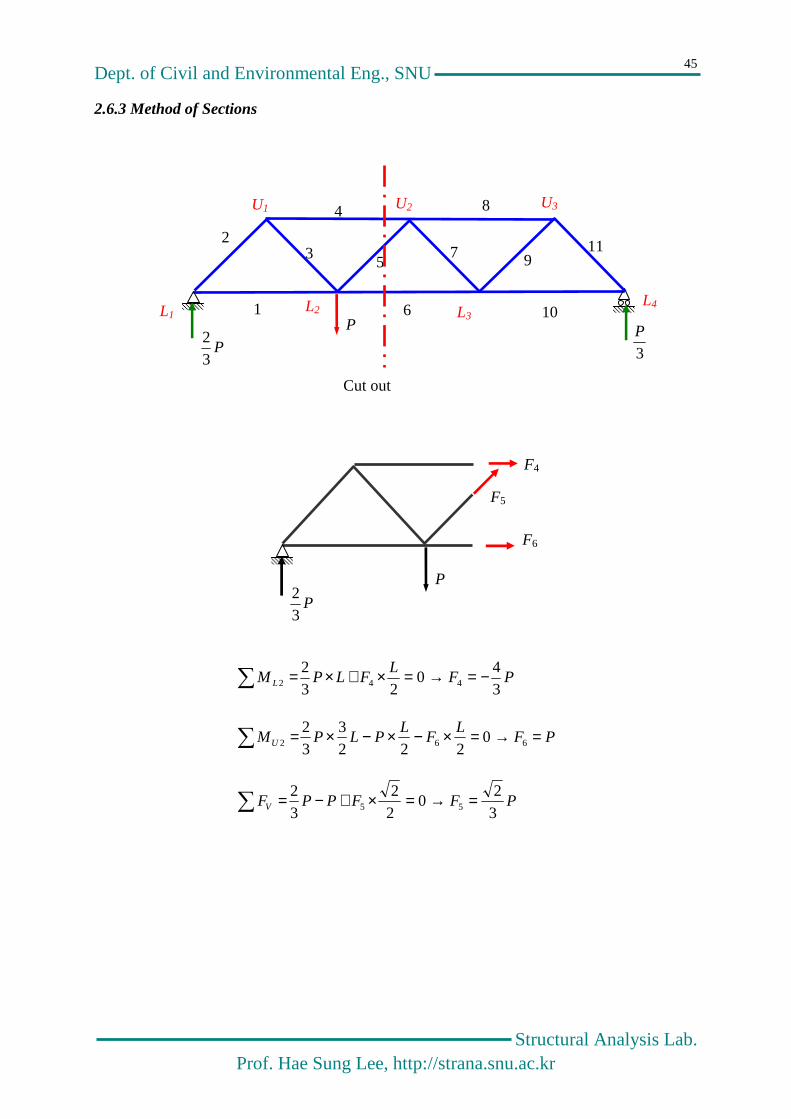
2.6.3 Method of Sections
PFL
FLPM L 34
023
2442 −=→=×+×=
PFL
FL
PLPMU =→=×−×−×= 662 0222
332
PFFPPFV 32
022
32
55 =→=×+−=
P
3P
P32
1
2 3
4
5
6
7
8
9
10
11
L1 L2 L3
U1
U
U2 U3
L4
Cut out
P
P32
F5
F4
F6

Dept. of Civil and Environmental Eng., SNU
Structural Analysis Lab. Prof. Hae Sung Lee, http://strana.snu.ac.kr
46
2.7 프레임 (Frame)
Dept. of Civil and Environmental Eng., SNU
Structural Analysis Lab. Prof. Hae Sung Lee, http://strana.snu.ac.kr
47
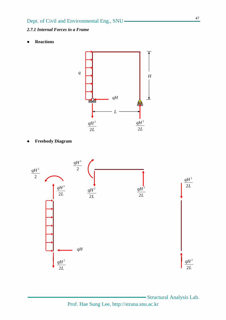
2.7.1 Internal Forces in a Frame
Reactions
Freebody Diagram
H
qH
L
L
qH
2
2
q
L
qH
2
2
2
2qH
qH
L
qH
2
2
L
qH
2
2
2
2qH
L
qH
2
2
L
qH
2
2
L
qH
2
2
L
qH
2
2

Dept. of Civil and Environmental Eng., SNU
Structural Analysis Lab. Prof. Hae Sung Lee, http://strana.snu.ac.kr
48
Axial, Shear and Moment diagram
Deflected Shape
L
qH
2
2
+ - Axial
L
qH
2
2
qH
-
+ Shear
L
qH
2
2
2
2qH
+
Moment
+
Dept. of Civil and Environmental Eng., SNU
Structural Analysis Lab. Prof. Hae Sung Lee, http://strana.snu.ac.kr
49
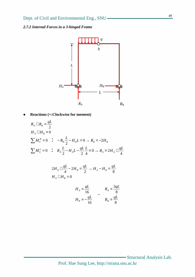
2.7.2 Internal Forces in a 3-hinged Frame
Reactions (+:Clockwise for mement)
02
=+
=+
BA
BA
HH
qLRR
= 0RhM : BBBB HRLH
LR 20
2−=→=−−
= 0LhM :
420
422qL
HRLqL
LHL
R AAAA +=→=−−
082
24
2
=+
=−→=−+
BA
BABA
HH
qLHH
qLH
qLH
16
16qL
H
qLH
B
A
−=
= →
8
83
qLR
qLR
B
A
=
=
L
L
HA HB
RA RB
h
q

Dept. of Civil and Environmental Eng., SNU
Structural Analysis Lab. Prof. Hae Sung Lee, http://strana.snu.ac.kr
50
Freebody Diagram
Axial, Shear and Moment diagram
16qL
16qL
8qL
16qL
83qL
16qL
8qL
83qL
8qL
16qL
16qL
16
2qL 16
2qL
16
2qL 16
2qL
16qL
16qL
- +
- 8
qL
+
83qL
Shear
83qL
8qL
16qL
- -
-
Axial

Dept. of Civil and Environmental Eng., SNU
Structural Analysis Lab. Prof. Hae Sung Lee, http://strana.snu.ac.kr
51
283
16
028
316
22
2
xqqLx
qLM
xqxqLx
qLM
−+−=
=−+−−
Deflected Shape
- -
-
Moment
- -
2
16qL 2
16qL
83qL
16
2qL
M
V

Dept. of Civil and Environmental Eng., SNU
Structural Analysis Lab. Prof. Hae Sung Lee, http://strana.snu.ac.kr
52
2.8 Arches
Dept. of Civil and Environmental Eng., SNU
Structural Analysis Lab. Prof. Hae Sung Lee, http://strana.snu.ac.kr
53
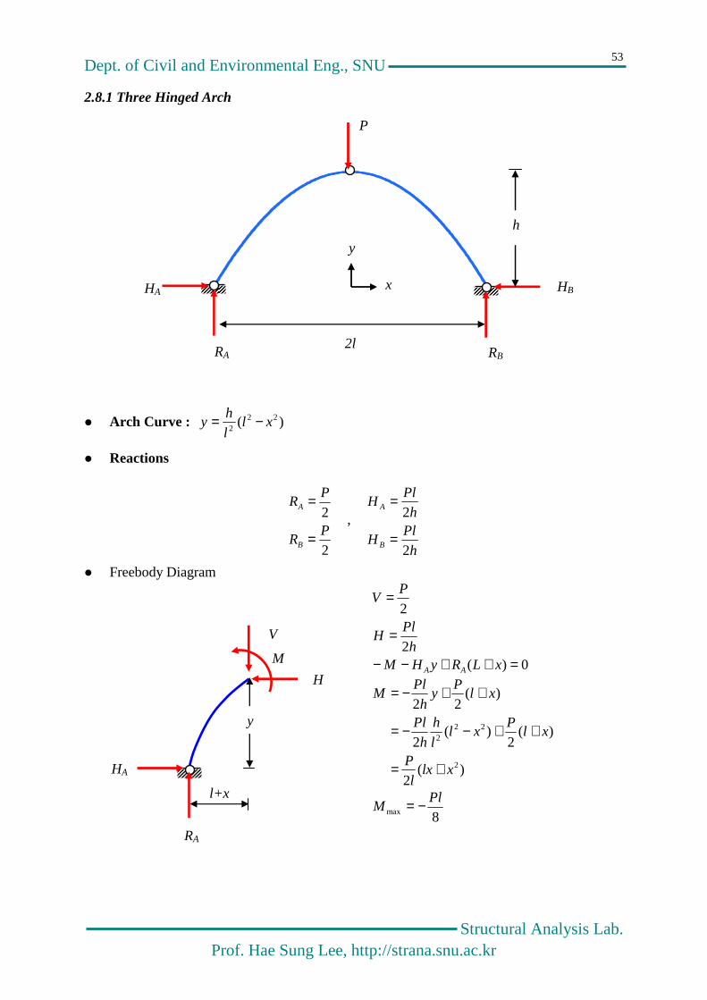
2.8.1 Three Hinged Arch
Arch Curve : )( 22
2xl
l
hy −=
Reactions
2
2P
R
PR
B
A
=
= ,
h
PlH
h
PlH
B
A
2
2
=
=
Freebody Diagram
h
PlH
PV
2
2
=
=
0)( =++−− xLRyHM AA
)(2
)(2
)(2
)(22
2
222
xlxl
P
xlP
xll
h
h
Pl
xlP
yh
PlM
+=
++−−=
++−=
8max
PlM −=
HA
RA
HB
RB
P
h
2l
x
y
HA
RA
V
H
M
y
l+x

Dept. of Civil and Environmental Eng., SNU
Structural Analysis Lab. Prof. Hae Sung Lee, http://strana.snu.ac.kr
54
Axial force and Shear Force
θθθ−θ
=
→
θ+θ=θ−θ=
S
A
V
H
SAV
SAH
cossin
sincos
cossin
sincos
θθ−θθ
=
→
V
H
S
A
cossin
sincos
224224
2
2
4
2sin ,
4cos
2tan
xhl
hx
xhl
l
l
hxy
+
−=θ+
=θ
−=′=θ
)2
(4
cos2
sin2
)2
(4
sin2
cos2
2
224
23
224
llx
xhl
PP
h
PlS
h
xhl
xhl
PP
h
PlA
−−+
=θ−θ=
−
+−=θ−θ−=
Deflected Shape
V
H
A S θ
Dept. of Civil and Environmental Eng., SNU
Structural Analysis Lab. Prof. Hae Sung Lee, http://strana.snu.ac.kr
55
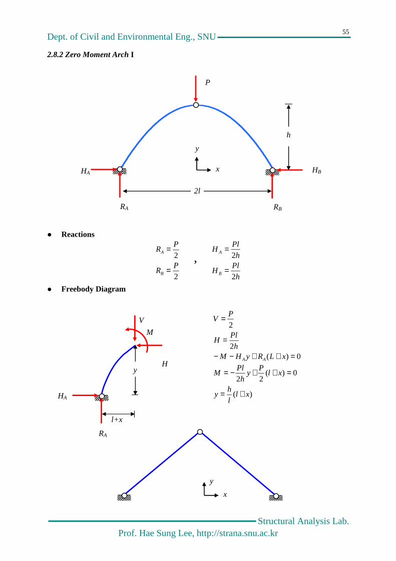
2.8.2 Zero Moment Arch I
Reactions
2
2P
R
PR
B
A
=
= ,
h
PlH
h
PlH
B
A
2
2
=
=
Freebody Diagram
h
PlH
PV
2
2
=
=
0)( =++−− xLRyHM AA
)(
0)(22
xll
hy
xlP
yh
PlM
+=
=++−=
HA
RA
HB
RB
P
h
2l
x
y
H
HA
RA
V
M
y
l+x
x
y
Dept. of Civil and Environmental Eng., SNU
Structural Analysis Lab. Prof. Hae Sung Lee, http://strana.snu.ac.kr
56
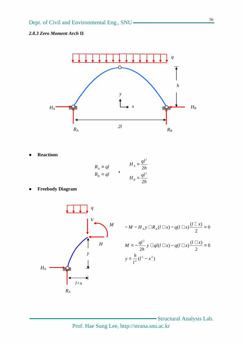
2.8.3 Zero Moment Arch II
Reactions
qlR
qlR
B
A
== ,
h
qlH
h
qlH
B
A
2
22
2
=
=
Freebody Diagram
02
)()()( =++−++−− xl
xlqxlRyHM AA
)(
02
)()()(
2
222
2
xll
hy
xlxlqxlqly
h
qlM
−=
=++−++−=
HA
RA
HB
RB
q
h
2l
x
y
HA
RA
V
H
M
y
l+x
q
Dept. of Civil and Environmental Eng., SNU
Structural Analysis Lab. Prof. Hae Sung Lee, http://strana.snu.ac.kr
57
Chapter 3
Principle of Virtual Work
The principle of virtual work is the most important subject in the area of the structural analysis !!!!
Dept. of Civil and Environmental Eng., SNU
Structural Analysis Lab. Prof. Hae Sung Lee, http://strana.snu.ac.kr
58
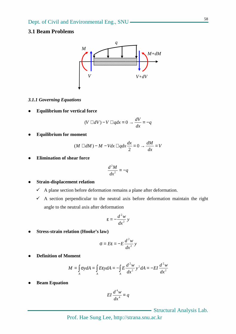
3.1 Beam Problems
3.1.1 Governing Equations
Equilibrium for vertical force
qdx
dVqdxVdVV −=→=+−+ 0)(
Equilibrium for moment
Vdx
dMdxqdxVdxMdMM =→=+−−+ 0
2)(
Elimination of shear force
qdx
Md −=2
2
Strain-displacement relation
A plane section before deformation remains a plane after deformation.
A section perpendicular to the neutral axis before deformation maintain the right
angle to the neutral axis after deformation
ydx
wd2
2
−=ε
Stress-strain relation (Hooke’s law)
ydx
wdEE
2
2
−=ε=σ
Definition of Moment
2
22
2
2
dx
wdEIdAy
dx
wdEydAEydAM
AAA
−=−=ε=σ=
Beam Equation
qdx
wdEI =
4
4
M M+dM
V V+dV
q

Dept. of Civil and Environmental Eng., SNU
Structural Analysis Lab. Prof. Hae Sung Lee, http://strana.snu.ac.kr
59
3.1.2 Limit Process
Equilibrium for vertical force
qdx
dVq
x
Vq
x
VxqVVV
x−=→=+
∆∆→=+
∆∆→=∆+−∆+
→∆0)(lim00)(
0
Equilibrium for moment
0))()(1
(lim0)()()(0
00
=ξξ−∆ξ+∆
+−∆
∆→=ξξ−∆ξ++∆−−∆+ ∆
→∆
∆
dxxqx
Vx
MdxxqxVMMM
x
x
x
00)(),()0,(),(
lim)(1
lim)(lim
)(),(
00
00
00
=×−=ξ
ξ−=∆
−∆−=ξξξ+∆
−ξξ+
ξξξ+=ξ
=ξ→∆
∆
→∆
∆
→∆
xqd
xdQ
x
xQxxQdxq
xdxq
dxqxQ
x
x
x
x
x
3.1.3 Modelling of Concentrate loads - Dirac delta functions
0lim→ε
= = )( ξ−δ x
122
1lim)0
2
10(lim)(
00
00
=εε
=+ε
+=ξ−δ→ε
ε+ξ
ε+ξ
ε−ξ
ε−ξ
→ε ll
dxdxdxdxx
)()(2
)()(lim)(
2
1lim
)0)(2
1)(0)((lim)()(
00
00
0
ξ=ξ′=ε
ε−ξ−ε+ξ=ε
=
+ε
+=ξ−δ
→ε
ε+ξ
ε−ξ→ε
ε+ξ
ε+ξ
ε−ξ
ε−ξ
→ε
fFFF
dxxf
dxxfdxxfdxxfdxxxfll
ξ
∞
ξ
ε21
2ε
ξ
M M+∆M
V V+∆V
q
∆x
Dept. of Civil and Environmental Eng., SNU
Structural Analysis Lab. Prof. Hae Sung Lee, http://strana.snu.ac.kr
60
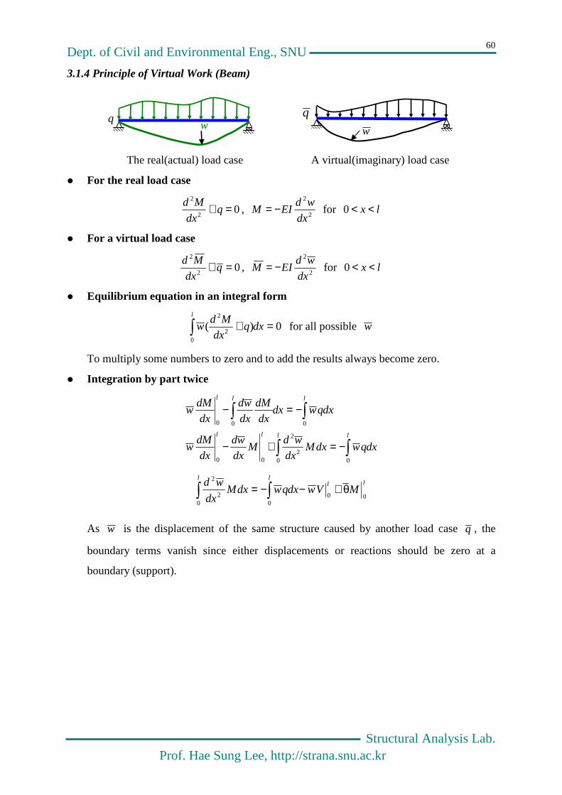
3.1.4 Principle of Virtual Work (Beam)
The real(actual) load case A virtual(imaginary) load case
For the real load case
02
2
=+ qdx
Md,
2
2
dx
wdEIM −= for lx <<0
For a virtual load case
02
2
=+ qdx
Md,
2
2
dx
wdEIM −= for lx <<0
Equilibrium equation in an integral form
0)(0
2
2
=+ dxqdx
Mdw
l
for all possible w
To multiply some numbers to zero and to add the results always become zero.
Integration by part twice
dxqwdxMdx
wdM
dx
wd
dx
dMw
dxqwdxdx
dM
dx
wd
dx
dMw
llll
lll
−=+−
−=−
002
2
00
000
llll
MVwdxqwdxMdx
wd00
002
2
θ+−−=
As w is the displacement of the same structure caused by another load case q , the
boundary terms vanish since either displacements or reactions should be zero at a
boundary (support).
q w w
q

Dept. of Civil and Environmental Eng., SNU
Structural Analysis Lab. Prof. Hae Sung Lee, http://strana.snu.ac.kr
61
Principle of virtual work
dxEI
MMdxM
dx
wd ll
−=00
2
2
dxqwdxEI
MM ll
=00
→ extWW δ=δ int
The internal virtual work is equal to the external virtual work if a beam satisfy the
equilibrium for the real and virtual load.
Equilibrium equation for load case q
0)(0
2
2
=+ dxqdx
Mdw
l
Virtual work expression
dxqwdxEI
MM ll
=00
Betti-Maxwell’s Reciprocal Theorem
dxEI
MMdx
EI
MM ll
=00
→ dxqwdxqwll
=00
Calculation of displacement for the load case q
dxqwdxEI
MM ll
=00
In case q system represents a single unit concentrated load applied at the position where
you want to calculate the displacement for q system.
)()( 0
0
0
0
xwdxxxwdxEI
MM ll
=−δ= → dxEI
MMxw
l
=0
0)(
Dept. of Civil and Environmental Eng., SNU
Structural Analysis Lab. Prof. Hae Sung Lee, http://strana.snu.ac.kr
62
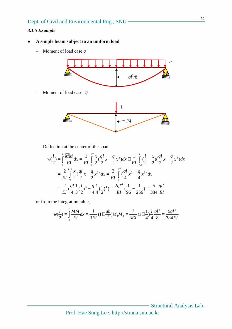
3.1.5 Example
A simple beam subject to an uniform load
– Moment of load case q
– Moment of load case q
– Deflection at the center of the span
EI
ql
EI
qllqlql
EI
dxxq
xql
EIdxx
qx
qlx
EI
dxxq
xqlxl
EIdxx
qx
qlx
EIdx
EI
MMlw
ll
l
l
ll
4443
2/
0
322/
0
2
2/
22/
0
2
0
384
5)
256
1
96
1(
2))
2(
4
1
4)
2(
3
1
4(
2
)44
(2
)22
(2
2
)22
)(22
(1
)22
(2
1)
2(
=−=−=
−=−=
−−+−==
or from the integration table,
EI
qlqll
EI
lMM
l
ab
EI
ldx
EI
MMlw
l
3845
84)
41
1(3
)1(3
)2
(42
3120
=+=+==
l/4
1
q
ql2/8

Dept. of Civil and Environmental Eng., SNU
Structural Analysis Lab. Prof. Hae Sung Lee, http://strana.snu.ac.kr
63
Values of Product Integrals L
LU dxMM0
Dept. of Civil and Environmental Eng., SNU
Structural Analysis Lab. Prof. Hae Sung Lee, http://strana.snu.ac.kr
64
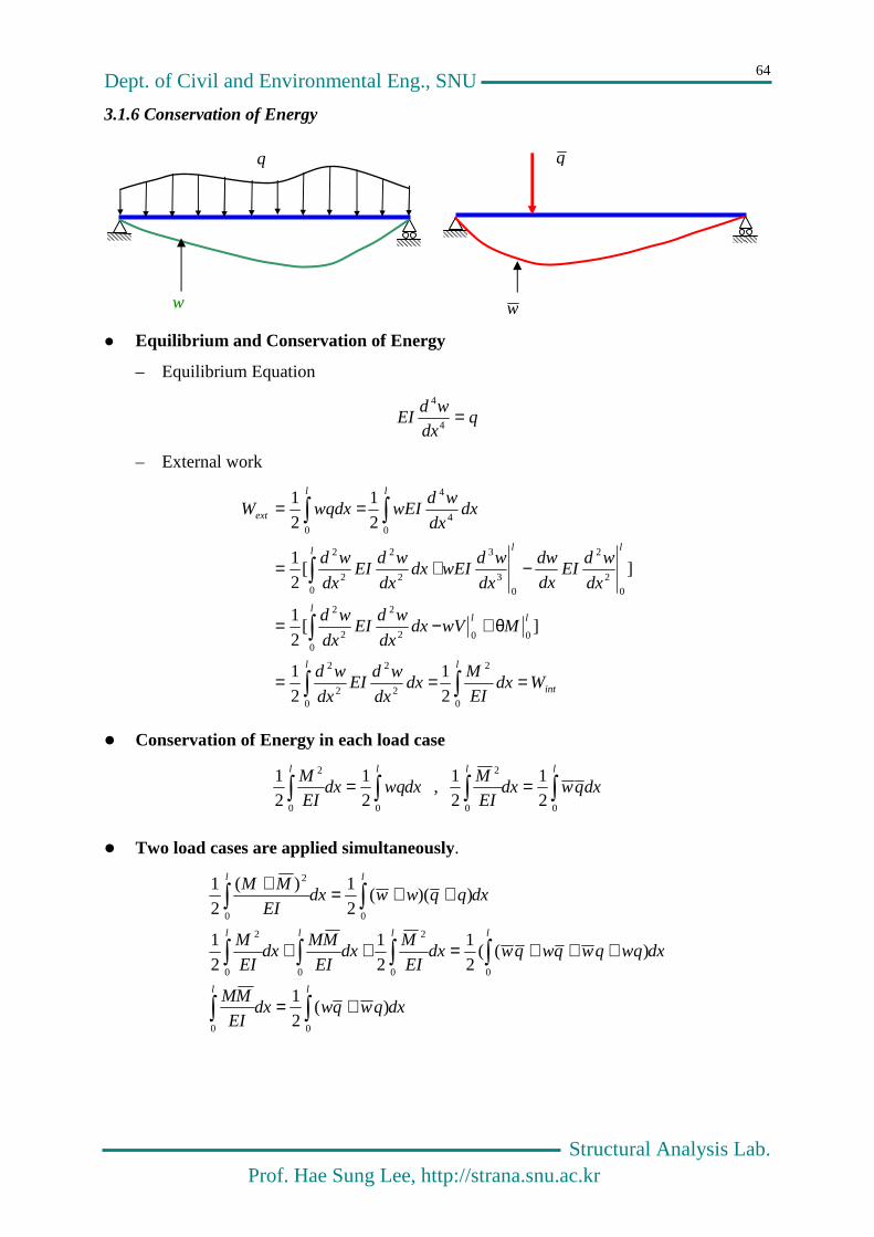
3.1.6 Conservation of Energy
Equilibrium and Conservation of Energy
– Equilibrium Equation
qdx
wdEI =
4
4
– External work
int
ll
lll
lll
ll
ext
WdxEI
Mdx
dx
wdEI
dx
wd
MwVdxdx
wdEI
dx
wd
dx
wdEI
dx
dw
dx
wdwEIdx
dx
wdEI
dx
wd
dxdx
wdwEIwqdxW
===
θ+−=
−+=
==
0
2
02
2
2
2
000
2
2
2
2
02
2
03
3
02
2
2
2
04
4
0
2
1
2
1
][2
1
][2
1
2
1
2
1
Conservation of Energy in each load case
dxwqdxEI
M ll
=00
2
21
21
, dxqwdxEI
M ll
=00
2
21
21
Two load cases are applied simultaneously.
dxqwqwdxEI
MM
dxwqqwqwqwdxEI
Mdx
EI
MMdx
EI
M
dxqqwwdxEI
MM
ll
llll
ll
+=
+++=++
++=+
00
00
2
00
2
00
2
)(2
1
)((2
1
2
1
2
1
))((2
1)(
2
1
w
q
w
q
Dept. of Civil and Environmental Eng., SNU
Structural Analysis Lab. Prof. Hae Sung Lee, http://strana.snu.ac.kr
65
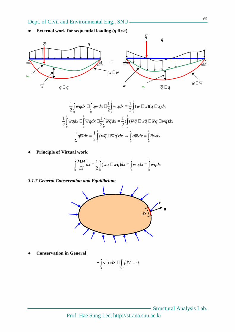
External work for sequential loading (q first)
=
dxwqdxwqdxqwqwdxwq
dxwqqwqwqwdxqwqdxwwqdx
dxqqwwdxqwdxwqwqdx
llll
lll l
lll l
=→+=
+++=++
++=++
0000
000 0
000 0
)(21
)((21
21
21
))((21
21
21
Principle of Virtual work
dxqwdxqwdxqwqwdxEI
MM llll
==+=0000
)(2
1
3.1.7 General Conservation and Equilibrium
Conservation in General
=+⋅−S V
fdVdS 0nv
v n
dS
w
q
w
q
ww +
w
q
w
q
ww +qq + qq +

Dept. of Civil and Environmental Eng., SNU
Structural Analysis Lab. Prof. Hae Sung Lee, http://strana.snu.ac.kr
66
– By divergence theorem,
⋅∇−=⋅−VS
dVdS vnv where ),,(),,(321 xxxzyx ∂
∂∂∂
∂∂=
∂∂
∂∂
∂∂=∇
=+⋅−∇=+⋅∇−=+⋅−VVS VV
dVffdVdVfdVdS 0)( vvnv
– Since the integral equation should hold for all systems,
0=+⋅∇− fv
Potential Problems
– The vector field of a system is defined by a gradient of a scalar function referred to as
a potential function
Φ∇⋅−= kv , ),,(zyx ∂Φ∂
∂Φ∂
∂Φ∂=Φ∇
– The famous Laplace equation for a conservative system.
0)( =+Φ∇⋅⋅∇=+⋅∇− ff kv
– If the system properties are homogeneous and isotropic, Φ∇−= kv
0)( 2 =+Φ∇=+Φ∇⋅∇=+⋅∇− fkfkfv or 02
2
2
2
2
2
=+∂
Φ∂+∂
Φ∂+∂
Φ∂f
zyx
3.1.8 Equilibrium in General
Force Equilibrium : === 0zyx FFF or 0=F
=+S V
dVdS 0bT or =+S V
ii dVbdST 0 for i = 1,2,3
– Suppose nT ⋅= σ or =
⋅=σ=3
1jijiji nT nσ ,
=
σσσσσσσσσ
=
3
2
1
333231
232221
131211
σσσ
σ ,
=
3
2
1
n
n
n
n
TT =
E, ν
uu= Su
St
V
x
y
z
bx
by
bz

Dept. of Civil and Environmental Eng., SNU
Structural Analysis Lab. Prof. Hae Sung Lee, http://strana.snu.ac.kr
67
– Divergence Theorem
0)( =+⋅∇=
+⋅∇=+⋅=+
V
ii
V V
ii
S V
ii
S V
ii
dVb
dVbdVdVbdSdVbdST
σ
σσ n
for i = 1,2,3
Since the integral equation should hold for all systems in equilibrium,
03
1
321 =+∂σ∂
=+∂σ∂
+∂σ∂
+∂σ∂
=+⋅∇ =
ij j
iji
iiiii b
xb
zyxbσ for i = 1,2,3 or
0
0
0
3333231
2232221
1131211
=+∂σ∂
+∂σ∂
+∂σ∂
=+∂σ∂
+∂σ∂+
∂σ∂
=+∂σ∂
+∂σ∂+
∂σ∂
bzyx
bzyx
bzyx
Moment Equilibrium : 0= iM for i=1, 2, 3 or 0=M
0=+×+× VVS
dVdVdS mfxvx
211231133223 , , σ=σσ=σσ=σ
– In case elasticity problems are potential problems
ii
i uC ∇⋅=σ
– However, to maintain symmetry condition of stress,
uC ∇= :σ or = = ∂
∂=σ3
1
3
1k l l
kijklij u
uC
– Equilibrium equation in terms of the potential functions
0):( =+∇⋅∇ buC
– What is σ, and why is σ related to a potential function in such a way?
out of scope of this class !

Dept. of Civil and Environmental Eng., SNU
Structural Analysis Lab. Prof. Hae Sung Lee, http://strana.snu.ac.kr
68
3.1.9 Displacement on boundaries
Virtual Work Expression
llll
MVwdxqwdxEI
MM00
00
θ−+=
llll
MVwdxqwdxEI
MM00
00
θ−+=
)0()0()()()0()0()()(0
0000
MlMlVwlVlwdxqwMVwdxqwdxEI
MM lll
ll
θ+θ−−+=θ−+=
By coinciding the positive direction of forces and displacement
)0()0()()()0()0()()(00
MlMlVwlVlwdxqwdxEI
MM ll
θ+θ+++=
Deflection of a cantilever beam subject to an end load
0)0( , 0)0( , 0)( , 1)( =θ=== wlMlV
q (real) system q (virtual) system
)0()0()()()0()0()()(00
MlMlVwlVlwdxqwdxEI
MM ll
θ+θ+++=
EI
PlPll
EI
lMM
EI
ldx
EI
MMlw
l
3))((
33)(
3
31
0
=−−===
Or, you can obtain the same answer by assuming the unit concentrate load is applied at
just left side of the boundary.
Rotation of a cantilever beam subject to an end load
0)0( , 0)0( , 1)( , 0)( =θ=== wlMlV
q (real) system q (virtual) system
)0()0()()()0()0()()(00
MlMlVwlVlwdxqwdxEI
MM ll
θ+θ+++=
EI
PlPl
EI
lMM
EI
ldx
EI
MMl
l
2)(1
22)(
2
31
0
−=−××===θ
P
-Pl
1
-l
P
-Pl
1

Dept. of Civil and Environmental Eng., SNU
Structural Analysis Lab. Prof. Hae Sung Lee, http://strana.snu.ac.kr
69
Rotation in the a body (or a structure)
– Modeling of a unit moment applied at x0
)0()0()()()0()0()()(00
MlMlVwlVlwdxqwdxEI
MM ll
θ+θ+++=
)()]2
()2
([1
lim
))]2
((1
))2
((1
[lim
0000
0
000
0
0
xdx
dwxwxw
dxxxxxwdxEI
MM
xx
ll
θ−=−=ε+−ε−ε
=
ε+−δε
−ε−−δε
=
=→ε
→ε
– by coinciding the positive direction of the rotational angle with that of the applied
moment.
dxEI
MMx
l
=θ0
0 )(
ε 1/ε 1/ε
x0
Dept. of Civil and Environmental Eng., SNU
Structural Analysis Lab. Prof. Hae Sung Lee, http://strana.snu.ac.kr
70
3.2 Principle of Virtual Work in General
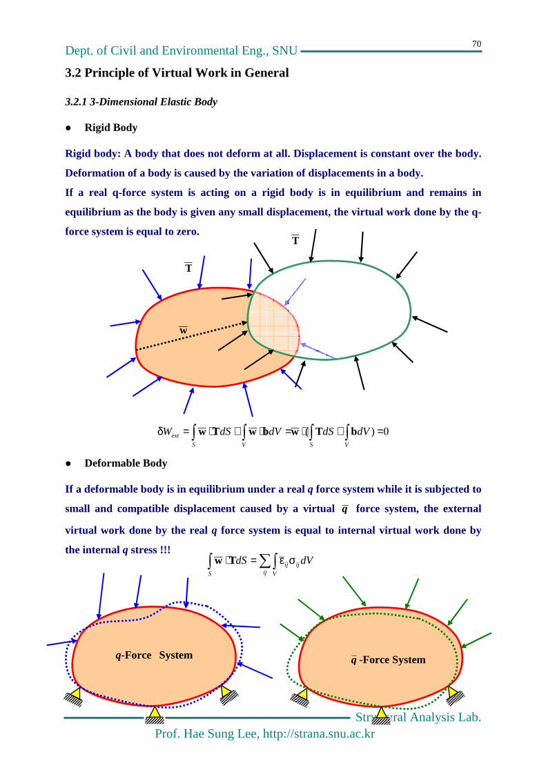
3.2.1 3-Dimensional Elastic Body
Rigid Body
Rigid body: A body that does not deform at all. Displacement is constant over the body.
Deformation of a body is caused by the variation of displacements in a body.
If a real q-force system is acting on a rigid body is in equilibrium and remains in
equilibrium as the body is given any small displacement, the virtual work done by the q-
force system is equal to zero.
0)( =+⋅=⋅+⋅=δS VS V
ext dVdSdVdSW bTwbwTw
Deformable Body
If a deformable body is in equilibrium under a real q force system while it is subjected to
small and compatible displacement caused by a virtual q force system, the external
virtual work done by the real q force system is equal to internal virtual work done by
the internal q stress !!!
q-Force System
q -Force System
w
T
T
dVdSij V
ijij
S
σε=⋅ Tw
Dept. of Civil and Environmental Eng., SNU
Structural Analysis Lab. Prof. Hae Sung Lee, http://strana.snu.ac.kr
71
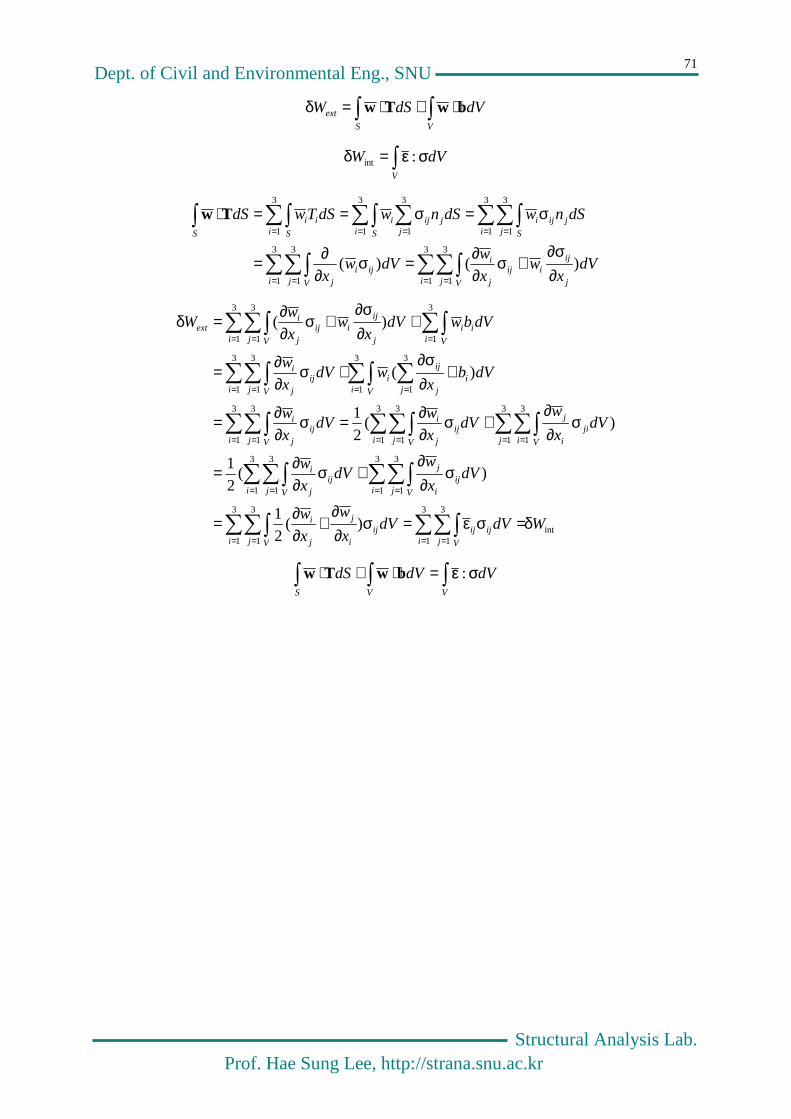
⋅+⋅=δS V
ext dVdSW bwTw
=δV
dVW σε :int
= == =
= == ==
∂σ∂
+σ∂∂=σ
∂∂=
σ=σ==⋅
3
1
3
1
3
1
3
1
3
1
3
1
3
1
3
1
3
1
)()(i j V j
ijiij
j
i
i j V
ijij
i j S
jijii S j
jijii S
ii
S
dVx
wx
wdVw
x
dSnwdSnwdSTwdSTw
int
3
1
3
1
3
1
3
1
3
1
3
1
3
1
3
1
3
1
3
1
3
1
3
1
3
1
3
1
3
1
3
1
3
1
3
1
3
1
3
1
3
1
)(2
1
)(2
1
)(2
1
)(
)(
WdVdVx
w
x
w
dVx
wdV
x
w
dVx
wdV
x
wdV
x
w
dVbx
wdVx
w
dVbwdVx
wx
wW
i j V
ijiji j V
iji
j
j
i
i j V
iji
j
i j V
ijj
i
j i V
jii
j
i j V
ijj
i
i j V
ijj
i
i V ji
j
iji
i j V
ijj
i
i V
iii j V j
ijiij
j
iext
δ=σε=σ∂∂
+∂∂=
σ∂∂
+σ∂∂=
σ∂∂
+σ∂∂=σ
∂∂=
+∂σ∂
+σ∂∂=
+∂σ∂
+σ∂∂=δ
= == =
= == =
= == == =
= == =
== =
=⋅+⋅S VV
dVdVdS σε :bwTw

Dept. of Civil and Environmental Eng., SNU
Structural Analysis Lab. Prof. Hae Sung Lee, http://strana.snu.ac.kr
72
3.2.2 General Framed Structures
)( τγ+σε=τγ+σε=σ⋅εe VVVVij V
ijij dVdVdVdVdVee
Internal virtual work by normal stress – bending moment
=−−=
==
==−−=σε
ee
ee
e
e
eeee
ll
ll
A
l
AVVV
dxEI
MMdx
EI
MEI
EI
M
dxdx
wdEI
dx
wddx
dx
wddAEy
dx
wd
dAdxydx
wd
dx
wdEdVy
dx
wd
dx
wdEdVy
dx
wdEy
dx
wddV
00
02
2
2
2
02
22
2
2
0
22
2
2
22
2
2
2
2
2
2
2
2
)()(
)(
)()(
Internal virtual work by normal stress – Axial Force
===σεee
eee
ll
AVV
dxEA
FFdx
A
FdA
EA
FdV
A
F
EA
FdV
00
)(
Internal virtual work by shear stress
QyIb
V
)(=τ and Q
yGIb
V
)(=γ where =
a
y
ydAQ
===τγee
eee
ls
l
AVV
VdxVGA
fdAdx
ybI
Q
G
VVQdV
yIb
VQ
yGIb
VdV
0022
2
)()()(
Total displacement
++=e
l ll
s
e ee
dxEA
FFdx
GA
VVfdx
EI
MMxw
0 00
0 )()(

Dept. of Civil and Environmental Eng., SNU
Structural Analysis Lab. Prof. Hae Sung Lee, http://strana.snu.ac.kr
73
3.2.3 Effect of Shear Deformation
For simple beam with a uniform load case
EI
qllwM 384
5)
2(
4
=
Shear Effect
▬ Shear force of load case q
▬ Shear force of load case q
▬ Deflection by shear force
GA
qlfVV
l
GA
fVdxV
GA
fVdxV
GA
fw ss
ls
ls
S
e
822
122 22/
00
====
GA
EI
l
f
EIql
GAqlf
w
w ss
M
s
40384
384/58/
24
2
==
for a rectangle section of bh× with steel
2
2
2
3
5.21240
6.238456
l
h
bhl
bh
w
w
M
s =×
××=
For small h/l, the effect of shear deformation can be neglected.
1/2
ql/2

Dept. of Civil and Environmental Eng., SNU
Structural Analysis Lab. Prof. Hae Sung Lee, http://strana.snu.ac.kr
74
3.3 Truss Problems
3.3.1 Principle of Virtual Work
From General principle
=++=
α+=α=⋅
ii
ii
e
l ll
s
iii
S
lEA
FFdx
EA
FFdx
GA
VVfdx
EI
MM
vuwdS
e ee
0 00
22
)(
coscoswq
From equilibrium equation
0 , 0)(
1
)(
1
=+−=+− ==
iim
j
ij
iim
j
ij YVXH for njni ,,1L= ( i
jij
ij
ij
ij
ij FVFH θ=θ= sin , cos )
where m(i), ijH and i
jV are the number of member connected to joint i, the horizontal
component and the vertical component of the bar force of j-th member connected to joint
i, respectively.
0])( )[(1
)(
1
)(
1
=+−++− = ==
njn
i
iiim
j
ij
iiim
j
ij vYVuXH
== ==
= ==
+=θ+θ
=+θ−++θ−
njn
i
iiiinjn
i
im
j
ij
ij
iim
j
ij
ij
i
njn
i
iiim
j
ij
ij
iiim
j
ij
ij
vYuXFvFu
vYFuXF
11
)(
1
)(
1
1
)(
1
)(
1
) ()sin cos(
0))sin( )cos((
Each member has two ends, and each end should be connected to two different joints.
Therefore adding all member end forces in a joint-wise fashion is equivalent to adding all
member end forces in a member-wise fashion because the member end forces of a
member
iY
iX
iF1−
ijF−
iimF )(−
iY
iX
pqF−
ijF
ijF−
pqF
i-th joint
p-th joint
k-th member
1
2

Dept. of Civil and Environmental Eng., SNU
Structural Analysis Lab. Prof. Hae Sung Lee, http://strana.snu.ac.kr
75
==
== ==
+=−θ+−θ
+=θ+θ
njn
i
iiiinmb
ikkkkkkkk
njn
i
iiiinjn
i
im
j
ij
ij
iim
j
ij
ij
i
vYuXvvFuuF
vYuXFvFu
11
1212
11
)(
1
)(
1
) ())(sin )(cos(
) ()sin cos(
==
====
=+
==∆=−θ+−θ
nmb
k k
kkknjn
i
iiii
nmb
k k
kkk
k
kknmb
kk
nmb
kkk
nmb
kkkkkkkk
EA
lFFvYuX
EA
lFF
EA
lFFlFvvuuF
11
1111
1212
) (
))(sin )((cos
Since α represnts the angle between the applied unit load and the displacement vector,
αcosiu are the displacement of the joint i in the direction of the applied unit load.
For vertical displacement For Horizontal displacement
iu αcosiu
kkk vv θ− sin)( 12
kk uu − cos)( 12
kθ
kθ
)( 12kk uu −
)( 12kk vv −By applying Betti-Maxwell reciprocal
theorem,
==
=+nmb
i k
kkknjn
i
iiii
EA
lFFvYuX
11
) (
The displacement of a joint i in a truss is
obtained by applying a unit load at a joint i
in an arbitrary direction.
=
=α=
α=+nmb
k k
kkki
iiiii
EA
lFF
vYuX
1
cos
cos
u
uX

Dept. of Civil and Environmental Eng., SNU
Structural Analysis Lab. Prof. Hae Sung Lee, http://strana.snu.ac.kr
76
3.3.2 Example
Real System Virtual System
Table for calculation of the deflection of a truss
Member EA
l F F EA
lFF
1 1 30 0.75 22.5
2 2 -30 2 -0.75 2 45 2
3 1 30 0.75 22.5
4 1 40 0.50 20
5 2 -10 2 0.25 2 -5 2
6 1 -30 -0.75 22.5
7 1 20 0 0
8 1 40 0.5 20
9 2 -10 2 -0.25 2 5 2
10 1 -30 -0.25 7.5
11 1 30 0.25 7.5
12 1 30 0.25 7.5
13 2 -30 2 -0.25 2 15 2
130+60 2
EA
l
EA
L215)260130( =+=δ
1
2
3
4
5
6
7
8
9
10
11
12
13
20 20 20

Dept. of Civil and Environmental Eng., SNU
Structural Analysis Lab. Prof. Hae Sung Lee, http://strana.snu.ac.kr
77
3.3.3 Conservation of Energy (Truss)
Equilibrium and Conservation of Energy
▬ Equilibrium Equation
0 , 0)(
1
)(
1
=+−=+− ==
iim
j
ij
iim
j
ij YVXH for njni ,,1L=
▬ External work
= ====
+=⋅∆=+=njn
i
iim
j
ij
iim
j
ij
njn
iii
njn
i
iiiiext vVuHvYuXW
1
)(
1
)(
111
) (21
21
)(21
P
int
nmb
k k
kkknmb
kkk
nmb
kkkkkkkkk
njn
i
im
j
ij
ij
iim
j
ij
ij
i
njn
i
iim
j
ij
ij
iim
j
ij
ij
njn
i
iim
j
ij
iim
j
ijext
WEA
lFFlF
vvFuuF
FvFu
vFuFvVuHW
==∆=
−θ+−θ=
θ+θ=
θ+θ=+=
==
=
= ==
= === ==
11
1
1212
1
)(
1
)(
1
1
)(
1
)(
11
)(
1
)(
1
2
1
2
1
))(sin )(cos(2
1
)sin cos(2
1
)sin cos(2
1) (
2
1
intext WW =
Conservation of Energy in each load case
==
⋅∆=njn
iii
nmb
k k
kk
EA
lF
11
2
21
21
P , ==
⋅∆=njn
iii
nmb
k k
kk
EA
lF
11
2
2
1
2
1P
Two load cases are applied simultaneously
====
⋅∆+⋅∆=→+⋅∆+∆=+ njn
iiiii
nmb
k k
kkknjn
iiiii
nmb
k k
kkk
EA
lFF
EA
lFF
1111
2
)(2
1)()(
2
1)(
2
1PPPP
External work for sequential loading (P first)
====
====
⋅∆=⋅∆→⋅∆=⋅∆+⋅∆
∆+⋅∆+⋅∆=+⋅∆+∆
njn
iii
njn
iii
njn
iii
njn
iiiii
njn
iii
njn
iii
njn
iii
njn
iiiii
1111
1111
)(21
21
21
)()(21
PPPPP
PPPPP
===
⋅∆=⋅∆=njn
iii
njn
iii
nmb
k k
kkk
EA
lFF
111
PP
===
δ=δ=njn
kkk
njn
kkk
nmb
k k
kkk lFlFEA
lFF
111

Dept. of Civil and Environmental Eng., SNU
Structural Analysis Lab. Prof. Hae Sung Lee, http://strana.snu.ac.kr
78
3.4 Frame Problems
++=∆e
l ll
s
e ee
dxEA
FFdx
GA
VVfdx
EI
MM
0 00
)(
where ∆ is the displacement in the direction of applied unit concentrate load in the virtual
system.
Moment Shear Axial
+=δ
2/
00
2 ll
M dxdxEI
EI
PllPlllPll
EIM 16
3)
446443(
2 =××+××=δ
l
l
HA HB=P/4
RA=P/2 RB=P/2
P
-
Pl/4
+
P/2
-
- +
P/4
- -
-
P/2 P/4
×
Pl/4 l/4
×
Pl/4 l/4

Dept. of Civil and Environmental Eng., SNU
Structural Analysis Lab. Prof. Hae Sung Lee, http://strana.snu.ac.kr
79
+=δ
2/
00
2 ll
sS dxdx
GA
f
GA
Plf)
PlPl(
GA
fdx
GA
VVf ss
V
sS 8
3
2
1
224
1
4
2 =××+××== δ
+=
2/
00
2 ll
sA dxdx
EAδ
EA
PlPlPl
EAdx
EA
AA
V
A 16
9)
4
1
422
1
2(
2 =××+××==δ
))(75.0)(56.11(16
)961(16
223
22
3
l
h
l
h
EI
Pl
EAl
EI
GAl
EIf
EI
Pl sASM
++=
++=δ+δ+δ=δ
In most cases, the deformation caused by the shear force and the axial force negligibly
small compared to that caused by the bending moment. If this is the case, the
displacement of a frame can be approximated by considering only the bending moment.
=∆e
le
dxEI
MM
0
×
P/4 1/4
×
P/2 1/2
×
P/4 1/4
×
P/2 1/2

Dept. of Civil and Environmental Eng., SNU
Structural Analysis Lab. Prof. Hae Sung Lee, http://strana.snu.ac.kr
80
This page is intentionally left blank.

Dept. of Civil and Environmental Eng., SNU
Structural Analysis Lab. Prof. Hae Sung Lee, http://strana.snu.ac.kr
81
Chapter 4
Analysis of Statically Indeterminate Beams
Rxθ L
xθ
1

Dept. of Civil and Environmental Eng., SNU
Structural Analysis Lab. Prof. Hae Sung Lee, http://strana.snu.ac.kr
82
4.1 Propped Cantilever Beam
Equilibrium equation
02
0
=−+
=+−−
lRl
qlM
qlRR
BA
BA
4.1.1. The first idea
=
+
Compatibility condition
00 =δ+δ xBR
– The end displacements of the cantilever beam for two loads cases are calculated by
the principle of virtual work.
EI
qll
qll
EIdx
EIdx
EI
MM ll
8))(
2(
4
1
1 42
00
0 =−−===δ
EI
lll
l
EIdx
EIdx
EI
MM ll
x 3))((
3
1
1 3
00
=−−===δ
q
RA RB
MA
δ0
R
xBR δ
-ql2/2
1
-l

Dept. of Civil and Environmental Eng., SNU
Structural Analysis Lab. Prof. Hae Sung Lee, http://strana.snu.ac.kr
83
Compatibility condition and the final solution
qlREI
lR
EI
qlBB 8
30
38
34
−=→=+ (up)
2
81
,85
qlMqlR AA −==
Moment Diagram
Deflected shape
4.1.2. The second idea
=
+
Compatibility condition
00 =θ+θ xAM
-ql2/2
3ql2/8
-ql2/8 -
2
1289
ql
3l/8
+ =
θ0
MA
xAM θ

Dept. of Civil and Environmental Eng., SNU
Structural Analysis Lab. Prof. Hae Sung Lee, http://strana.snu.ac.kr
84
– Rotional Angle at the fixed end
EI
qlqll
EIdx
EIdx
EI
MM ll
241
83
1
1 32
00
0 =×===θ
EI
ll
EIdx
EIdx
EI
MM ll
x 311
3
1
1
00
=××===θ
Compatibility condition and the final solution
23
81
0324
qlMEI
lM
EI
qlAA −=→=+
Other reactions by a free body diagram
=
ql2/8 1
1
ql/2 ql/2 ql/8
ql2/8
ql/8
+
3ql/8 5ql/8
ql2/8

Dept. of Civil and Environmental Eng., SNU
Structural Analysis Lab. Prof. Hae Sung Lee, http://strana.snu.ac.kr
85
4.2 Cantilever Beam with Spring Support
Robin BC (The third type BC)
)()( lkwlwEIV −=′′′−=
Primary structure
Compatibility Condition
wbeam(l)=δspring → spring0 δ−=δ+δ xBR
EIkl
klql
kEI
lEI
ql
Rk
R
EI
lR
EI
qlB
BB 38
31
3
838 3
3
3
4
34
+−=
+−=→−=+
As qlRk B 8
3, →∞→ , and As 0,0 →→ BRk
Deflected Shape for 3
100l
EIk =
δ0
BR
xBR δ
)(lkw
Dept. of Civil and Environmental Eng., SNU
Structural Analysis Lab. Prof. Hae Sung Lee, http://strana.snu.ac.kr
86
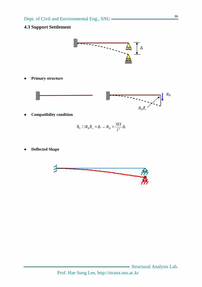
4.3 Support Settlement
Primary structure
Compatibility condition
∆=→∆=δ+δ30
3
l
EIRR BxB
Deflected Shape
∆
RB
xBR δ

Dept. of Civil and Environmental Eng., SNU
Structural Analysis Lab. Prof. Hae Sung Lee, http://strana.snu.ac.kr
87
4.4 Temperature Change
Primary structure
Curvature due to temperature change
dxTTdxTThd )()( 0102 −α−−α=θ
2
212 )(
dx
wd
h
TT
dx
d −=−α
=θ
baxxh
TTw ++
−α−= 212
2
)(
For simple beam, 0)()0( == lww → lh
TTa
2
)( 12 −α=
Comaptibility condition
00 =θ+θ xAM → 032
)( 12 =+−α
EI
lMl
h
TTA → EI
h
TTM A
)(
2
3 12 −α−=
T1
T2
θ0
MA
xAM θ
Dept. of Civil and Environmental Eng., SNU
Structural Analysis Lab. Prof. Hae Sung Lee, http://strana.snu.ac.kr
88
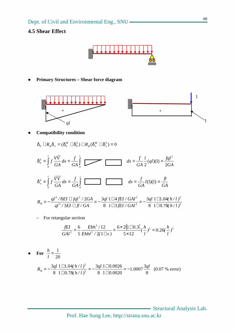
4.5 Shear Effect
Primary Structures – Shear force diagram
Compatibility condition
0)()( 000 =δ+δ+δ+δ=δ+δ Sx
MxB
SMxB RR
GA
fqlql
l
GA
fdx
GA
fdx
GA
VVf
llS
2)1)((
2
2
00
0 ====δ
GA
fll
GA
fdx
GA
fdx
GA
VVf
llSx ====δ )1)(1(
00
2
2
2
2
3
24
7801
0411
8
3
31
41
8
3
3
28
)l/h(.
)l/h(.ql
GAl/fEI
GAl/fEIql
GA/flEI/ql
GA/fqlEI/qlRB +
+−=++−=
++−=
– For retangular section
( ) 222
3
2260
125
30126
12
12
5
6)
l
h(.)
l
h(
.
)v(/Ehbl
/Ebh
GAl
fEI =×
+×=+
=
For 201=
l
h
8
300071
002001
002601
8
3
7801
0411
8
32
2 ql.
.
.ql
)l/h(.
)l/h(.qlRB −=
++−=
++−= (0.07 % error)
1
ql 1
+ +

Dept. of Civil and Environmental Eng., SNU
Structural Analysis Lab. Prof. Hae Sung Lee, http://strana.snu.ac.kr
89
For 101=
l
h
8
300261
007801
010401
8
3
7801
0411
8
32
2 ql.
.
.ql
)l/h(.
)l/h(.qlRB −=
++−=
++−= (0.26 % error)
For 51=
l
h
8
301011
031201
041601
8
3
7801
0411
8
32
2 ql.
.
.ql
)l/h(.
)l/h(.qlRB −=
++−=
++−= (1.0 % error)
You may neglect the effect of the shear deformation in most cases !!
4.6 2-Span Continuous Beam
Primary structure
Compatibility
)( 00RxB
RLxB
L MM θ+θ−=θ+θ → 0)(00 =θ+θ+θ+θ Rx
LxB
RL M
EI EI q
ql
Rxθ L
xθ
1
4
2ql 8
2ql
q
ql
R0θ L
0θ
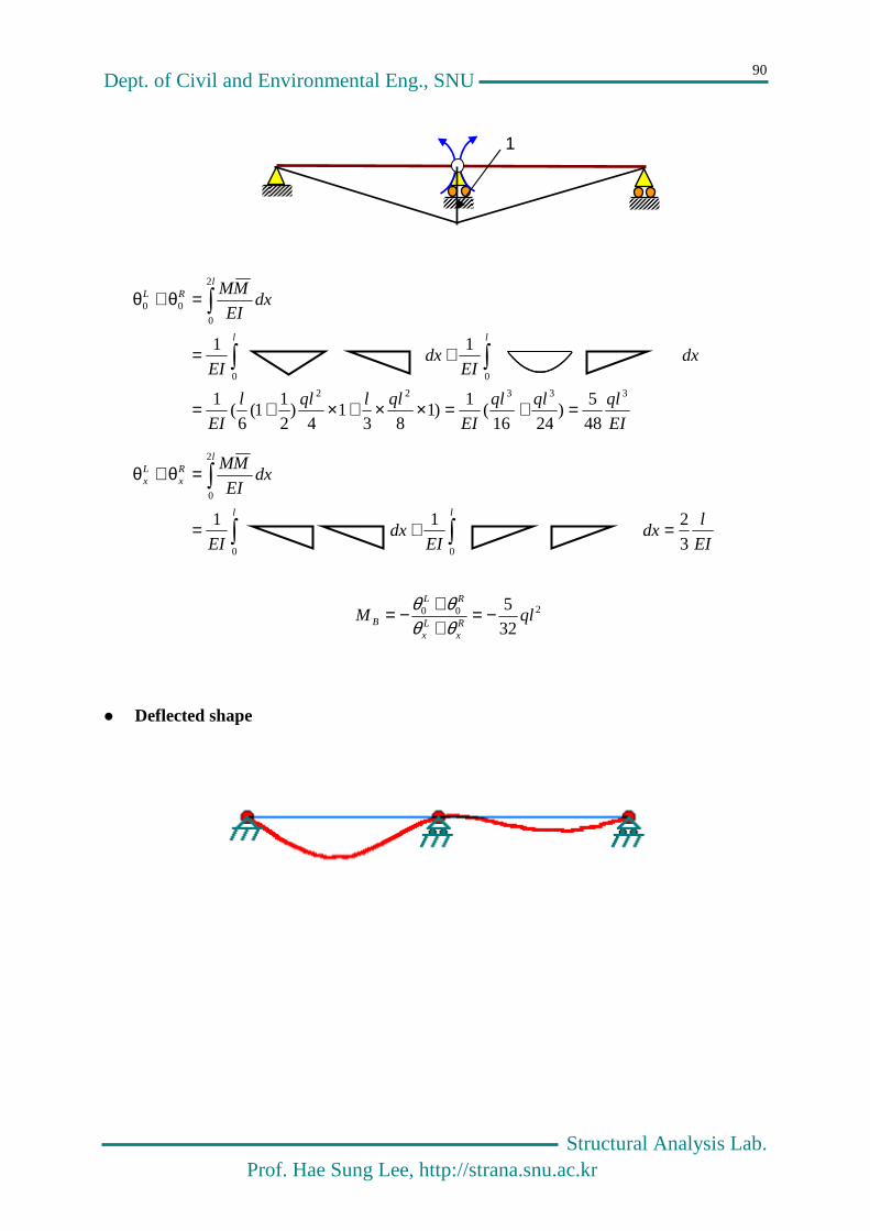
Dept. of Civil and Environmental Eng., SNU
Structural Analysis Lab. Prof. Hae Sung Lee, http://strana.snu.ac.kr
90
EI
qlqlql
EI
qllqll
EI
dxEI
dxEI
dxEI
MM
ll
lRL
33322
00
2
0
00
48
5)
2416(
1)1
831
4)
2
11(
6(
1
1
1
=+=××+×+=
+=
=θ+θ
EI
ldx
EIdx
EI
dxEI
MM
ll
lRx
Lx
3
2
1
1
00
2
0
=+=
=θ+θ
200
325
qlMRx
Lx
RL
B −=++−=
θθθθ
Deflected shape
1

Dept. of Civil and Environmental Eng., SNU
Structural Analysis Lab. Prof. Hae Sung Lee, http://strana.snu.ac.kr
91
4.7 Fixed-Fixed End Beam
4.7.1. Primary Structure type I
0-th load case (X0)
1st load case (X1)
2nd load case (X2)
ijδ : the deflection in the direction of the unit concentrated load in load case i caused by
load case j. In most of engineering problem, the first subscript denotes results while the
second subscript indicates causes.
EI
qlqll
l
EIdx
EI
MMl
8)
2()(
4
1 42
0
0110 =−×−×==δ
EI
qlqll
EIdx
EI
MMl
6)
2(1
3
1 32
0
0220 −=−××==δ
EI
lll
l
EIdx
EI
MMl
3)()(
3
1 3
0
1111 =−×−×==δ
EI
ll
l
EIdx
EI
MMl
21)(
2
1 2
0
212112 −=×−==δ=δ
EI
ll
EIdx
EI
MMl
=××==δ 111
0
2222
q
RA RB
MA MB
-ql2/2
M0
1
-l
M1
1 1
M2
Dept. of Civil and Environmental Eng., SNU
Structural Analysis Lab. Prof. Hae Sung Lee, http://strana.snu.ac.kr
92
Compatibility condition (Flexibility equation)
=+−−
=−+→
=δ+δ+δ=δ+δ+δ
026
0238
0
0
21
23
2
2
1
34
22212120
21211110
XEI
lX
EI
l
EI
ql
XEI
lX
EI
l
EI
ql
XX
XX
21
qlX −= ,
12
2
2
qlX −=
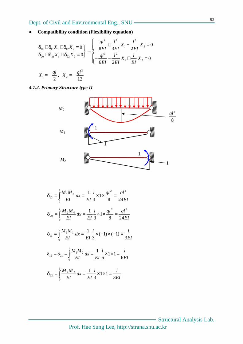
4.7.2. Primary Structure type II
EI
qlqll
EIdx
EI
MMl
2481
3
1 42
0
0110 =××==δ
EI
qlqll
EIdx
EI
MMl
2481
3
1 32
0
0220 =××==δ
EI
ll
EIdx
EI
MMl
3)1()1(
3
1
0
1111 =−×−×==δ
EI
ll
EIdx
EI
MMl
611
61
δδ
0
212112 =××===
EI
ll
EIdx
EI
MMl
311
3
1
0
2222 =××==δ
M0
M2
1
1
M1
1
1
8
2ql

Dept. of Civil and Environmental Eng., SNU
Structural Analysis Lab. Prof. Hae Sung Lee, http://strana.snu.ac.kr
93
Compatibility condition (Flexibility equation)
=++
=++→
=δ+δ+δ=δ+δ+δ
03624
06324
0
0
21
3
21
3
22212120
21211110
XEI
lX
EI
l
EI
ql
XEI
lX
EI
l
EI
ql
XX
XX
12
2
21
qlXX −==
Reactions and Moment Diagrams
Deflected Shape
24
2ql 12
2ql−
2
ql 2
ql
Dept. of Civil and Environmental Eng., SNU
Structural Analysis Lab. Prof. Hae Sung Lee, http://strana.snu.ac.kr
94
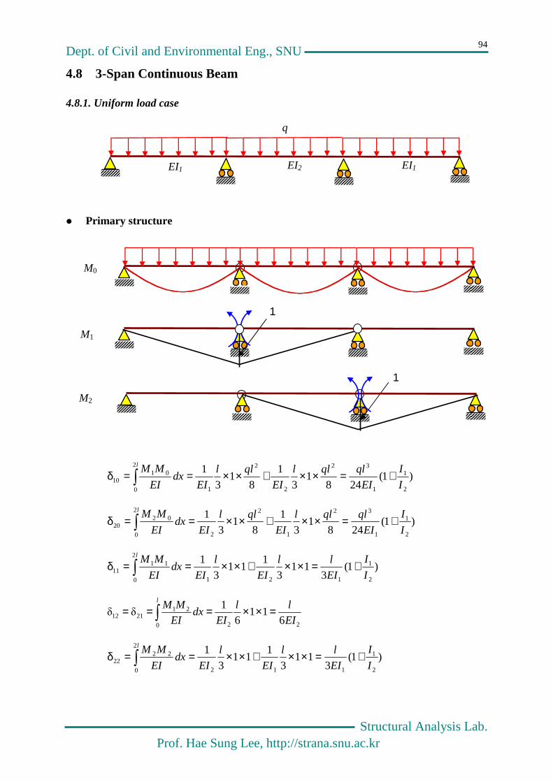
4.8 3-Span Continuous Beam
4.8.1. Uniform load case
Primary structure
)1(248
13
1
81
3
1
2
1
1
32
2
2
1
2
0
0110 I
I
EI
qlqll
EI
qll
EIdx
EI
MMl
+=××+××==δ
)1(248
13
1
81
3
1
2
1
1
32
1
2
2
2
0
0220 I
I
EI
qlqll
EI
qll
EIdx
EI
MMl
+=××+××==δ
)1(3
113
111
3
1
2
1
121
2
0
1111 I
I
EI
ll
EI
l
EIdx
EI
MMl
+=××+××==δ
220
212112 6
116
1δδ
EI
ll
EIdx
EI
MMl
=××===
)1(3
113
111
3
1
2
1
112
2
0
2222 I
I
EI
ll
EI
l
EIdx
EI
MMl
+=××+××==δ
EI1 EI2
q
EI1
M0
1
M1
1
M2

Dept. of Civil and Environmental Eng., SNU
Structural Analysis Lab. Prof. Hae Sung Lee, http://strana.snu.ac.kr
95
Compatibility condition (Flexibility equation)
=++++
=++++→
=δ+δ+δ=δ+δ+δ
0)1(36
)1(24
06
)1(3
)1(24
0
0
22
1
11
22
1
1
3
22
12
1
12
1
1
3
22212120
21211110
XI
I
EI
lX
EI
l
I
I
EI
ql
XEI
lX
I
I
EI
l
I
I
EI
ql
XX
XX
2
1
2
1
221
5.11
1
8
1
I
II
I
qlXX+
+−==
In case 21 II = , 221 10
1qlXX −==
4.8.2. Complicated Load Case
Primary structure
M0
EI EI
q
EI
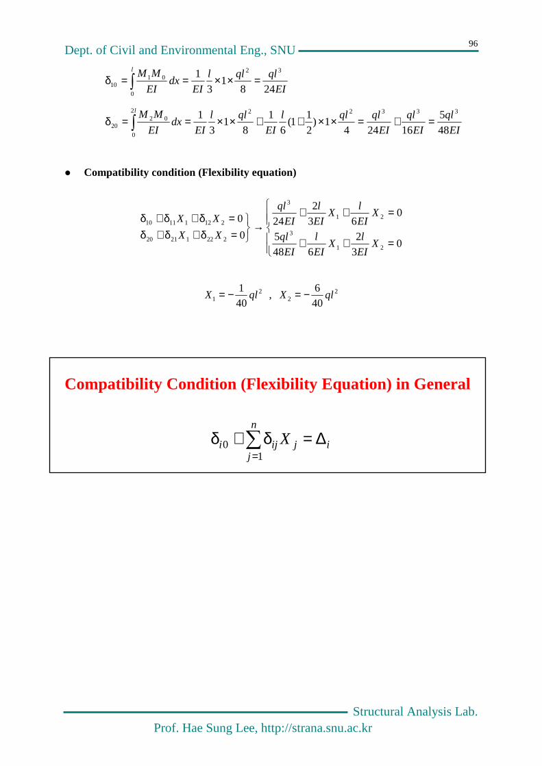
Dept. of Civil and Environmental Eng., SNU
Structural Analysis Lab. Prof. Hae Sung Lee, http://strana.snu.ac.kr
96
EI
qlqll
EIdx
EI
MMl
2481
3
1 32
0
0110 =××==δ
EI
ql
EI
ql
EI
qlqll
EI
qll
EIdx
EI
MMl
48
5
162441)
2
11(
6
1
81
3
1 333222
0
0220 =+=××++××==δ
Compatibility condition (Flexibility equation)
=++
=++→
=δ+δ+δ=δ+δ+δ
03
2
648
5
063
2
240
0
21
3
21
3
22212120
21211110
XEI
lX
EI
l
EI
ql
XEI
lX
EI
l
EI
ql
XX
XX
2
1 401
qlX −= , 22 40
6qlX −=
Compatibility Condition (Flexibility Equation) in G eneral
=
∆=δ+δn
jijiji X
10

Dept. of Civil and Environmental Eng., SNU
Structural Analysis Lab. Prof. Hae Sung Lee, http://strana.snu.ac.kr
97
Chapter 5
Analysis of Statically Indeterminate Trusses
1 1
1
21− 2
1−
21−

Dept. of Civil and Environmental Eng., SNU
Structural Analysis Lab. Prof. Hae Sung Lee, http://strana.snu.ac.kr
98
5.1 Various Types of Trusses
Determinate Truss
Externally Indeterminate Truss
Internally Indeterminate Truss
Mixed Indeterminate Truss

Dept. of Civil and Environmental Eng., SNU
Structural Analysis Lab. Prof. Hae Sung Lee, http://strana.snu.ac.kr
99
5.2 A Simple Truss
5.2.1 Method - I
+
P
X
P
P
=

Dept. of Civil and Environmental Eng., SNU
Structural Analysis Lab. Prof. Hae Sung Lee, http://strana.snu.ac.kr
100
Primary structure
At L1
0
75.06.0
25.1
18.0
1
31
3
==+
==
F
FF
F
F
P -1.0
1.25
0
-0.75 0
1
0.75 0.75
F1 F3
0.75
1
①,②,④:0.5A
③,⑤:A
P ②
①
③
④
⑤
L
0.75L
L1 L2
U1 U2

Dept. of Civil and Environmental Eng., SNU
Structural Analysis Lab. Prof. Hae Sung Lee, http://strana.snu.ac.kr
101
At L2
75.0 , 25.1
18.0
06.0
45
5
54
−===
=+
FF
F
FF
At U1
1 , 75.0
08.0
06.0
21
52
51
−=−==+=+
FF
FF
FF
1
-1.0
1.25
1.25
-0.75
1
-0.75
F4 F5
1
F1
F2
F5
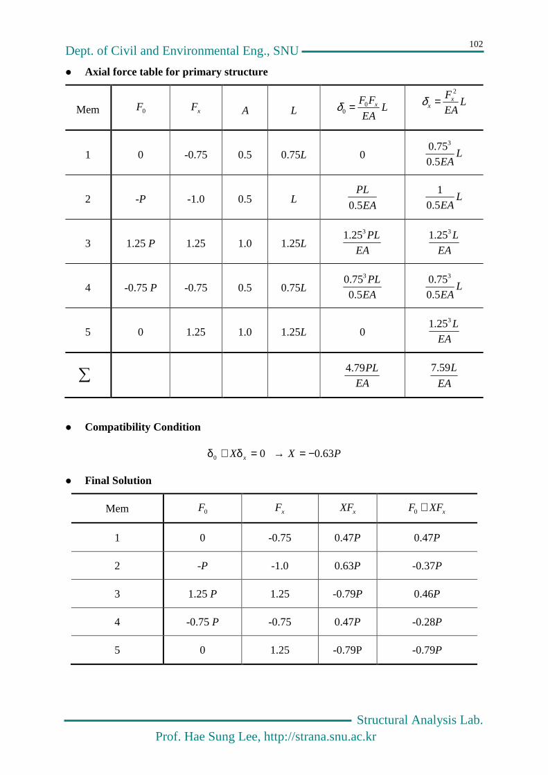
Dept. of Civil and Environmental Eng., SNU
Structural Analysis Lab. Prof. Hae Sung Lee, http://strana.snu.ac.kr
102
Axial force table for primary structure
Mem 0F xF A L LEA
FF x00 =δ L
EA
Fxx
2
=δ
1 0 -0.75 0.5 0.75L 0 LEA5.0
75.0 3
2 -P -1.0 0.5 L EA
PL
5.0 L
EA5.01
3 1.25 P 1.25 1.0 1.25L EA
PL325.1
EA
L325.1
4 -0.75 P -0.75 0.5 0.75L EA
PL
5.075.0 3
LEA5.0
75.0 3
5 0 1.25 1.0 1.25L 0 EA
L325.1
EA
PL79.4
EA
L59.7
Compatibility Condition
00 =δ+δ xX PX 63.0−=→
Final Solution
Mem 0F xF xXF xXFF +0
1 0 -0.75 0.47P 0.47P
2 -P -1.0 0.63P -0.37P
3 1.25 P 1.25 -0.79P 0.46P
4 -0.75 P -0.75 0.47P -0.28P
5 0 1.25 -0.79P -0.79P

Dept. of Civil and Environmental Eng., SNU
Structural Analysis Lab. Prof. Hae Sung Lee, http://strana.snu.ac.kr
103
5.2.2 Method - II
P
+
P
X
X
=

Dept. of Civil and Environmental Eng., SNU
Structural Analysis Lab. Prof. Hae Sung Lee, http://strana.snu.ac.kr
104
Compatibility condition
EA
XLX x −=δ+δ0
Primary structure
-1.0P P
1.25P -0.75P
P
0
0.75P 0.75P
-0.8
1.0 -0.6
0.8
-0.6
0.8
1
1
X
= +
F0 Fx
EA
XL

Dept. of Civil and Environmental Eng., SNU
Structural Analysis Lab. Prof. Hae Sung Lee, http://strana.snu.ac.kr
105
Axial force table for primary structure
Mem 0F xF A L LEA
FF x00 =δ L
EA
FF xxx =δ
1 0 -0.6 0.5 0.75L 0 EA
L54.0
2 -P -0.8 0.5 L EA
PL6.1 EA
L28.1
3 1.25 P 1.0 1.0 1.25 L EA
PL56.1 EA
PL25.1
`4 -0.75 P -0.6 0.5 0.75 L EA
PL68.0
EA
PL54.0
5 - - 1.0 - - -
EA
PL84.3 EA
L61.3
EA
XLX x −=δ+δ0 → X
EA
LX
EA
L
EA
PL 25.161.384.3 −=+
PPX 79.086.4
84.3 −==
PXH 63.08.02 −==
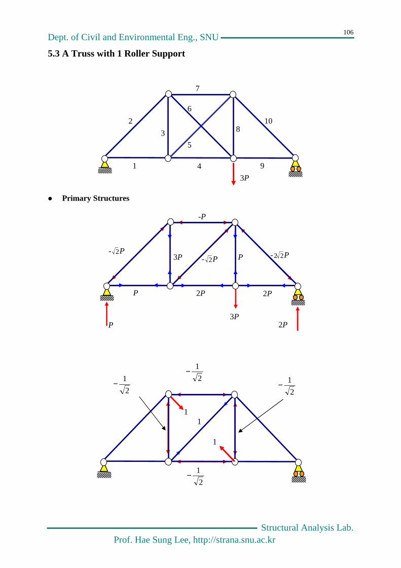
Dept. of Civil and Environmental Eng., SNU
Structural Analysis Lab. Prof. Hae Sung Lee, http://strana.snu.ac.kr
106
5.3 A Truss with 1 Roller Support
Primary Structures
1
2
3
4
5
6
7
8
9
10
3P
P 2P 3P
-P
2P P 2P
P 3P - 2P - 2P - 22 P
1
1
1
2
1− 2
1−
2
1−
2
1−

Dept. of Civil and Environmental Eng., SNU
Structural Analysis Lab. Prof. Hae Sung Lee, http://strana.snu.ac.kr
107
Axial force table for primary structure
Mem F 0
xF EA
L L
EA
FF x00 =δ L
EA
FF xxx =δ
1 P 0 1 0 0
2 P2− 0 2 0 0
3 P 2
1− 1 2
P− 2
1
4 P2 2
1− 1 2
2P− 2
1
5 P2− 1 2 P2− 2
6 - - 2 - -
7 P− 2
1− 1 2
P
2
1
8 P3 2
1− 1 2
3P− 2
1
9 P2 0 1 0 0
10 P22− 0 2 0 0
-5.54P 3.41
Compatibility condition
LEA
XXx 20 −=δ+δ
PXXXP 15.141.141.354.5 =→−=+−
X

Dept. of Civil and Environmental Eng., SNU
Structural Analysis Lab. Prof. Hae Sung Lee, http://strana.snu.ac.kr
108
Temperature change and fabrication error
)22(0 fx LTLEA
XX ∆+∆α+−=δ+δ
In case of no external loads
)2(21.0)2(82.4 ff LTL
EAXLTX
EA
L ∆+∆−=→∆+∆−= αα
5.4 Truss with Two Hinge Supports
Primary structure and compatibility condition
0
2
22212120
121211110
=δ+δ+δ
−=δ+δ+δ
XX
LEA
XXX
3P 2P P
X1
1
2
3
4
5
6
7
8
9
X1
X2
X1
X1

Dept. of Civil and Environmental Eng., SNU
Structural Analysis Lab. Prof. Hae Sung Lee, http://strana.snu.ac.kr
109
– F0
– F1
– F2
1
1
1 1 1
2P P 3P
-P
2P 2P P
P 3P - 2P - 2P - 22 P
2
1−
1 1
1
2
1− 2
1−
2
1−

Dept. of Civil and Environmental Eng., SNU
Structural Analysis Lab. http://strana.snu.ac.kr
110
Axial force table for the primary structure
Mem 0F 1F 2F
EA
L L
EA
FF 10 LEA
FF 20 LEA
FF 11 LEA
FF 21 LEA
FF 22
1 P2 0 1 1 0 P2 0 0 1
2 P22− 0 0 2 0 0 0 0 0
3 P3 2
2− 0 1 P223− 0
2
1 0 0
4 P2 2
2− 1 1 P222− P2 2
1
2
2− 1
5 P2− 1 0 2 P2− 0 2 0 0
6 P− 2
2− 0 1 P2
2 0
2
1 0 0
7 P 2
2− 0 1 P2
2− 0 2
1 0 0
8 P 0 1 1 0 P 0 0 1
9 P2− 0 0 2 0 0 0 0 0
-5.54P 5P 3.41 -0.71 3
0371.05
41.171.041.354.5
21
121
=+−−=−+−
XXP
XXXP →
PXX
PXX
5371.0
54.571.082.4
21
21
−=+−=−
→ PX
PX
44.1
94.0
2
1
−==

Dept. of Civil and Environmental Eng., SNU
Structural Analysis Lab. Prof. Hae Sung Lee, http://strana.snu.ac.kr
111
Chapter 6
Analysis of Statically Indeterminate Frames
EI
w

Dept. of Civil and Environmental Eng., SNU
Structural Analysis Lab. Prof. Hae Sung Lee, http://strana.snu.ac.kr
112
6.1 Γ-shaped Frame-I
Equilibrium equation
02
0
=−−
=++
lRPl
M
PRR
CA
CA
6.1.1 Primary Structure type I
+
δ0
P 1
Rcδx
P
RA
MA
RC l
l

Dept. of Civil and Environmental Eng., SNU
Structural Analysis Lab. Prof. Hae Sung Lee, http://strana.snu.ac.kr
113
Compatibility condition
0δ δ0 =+ xCR
End Displacements
333
2
000
0
48
29)
48
5
2(
1)}
2)(2
2(
6
1
2))(
2({
1
1
1
PlEI
PlPl
EI
Pll
lll
Pll
EI
dxEI
dxEI
dxEI
MMl
ll
=+=−−−×+−−=
+==δ
333
000
3
4)
3
1(
1)})((
3))(({
1
1
1
lEI
llEI
lll
lllEI
dxEI
dxEI
dxEI
MM lll
x
=+=−−+−−=
+==δ
Compatibility condition and the final solution
03
44829 33 =+ lR
EIPl
EI C
PPRC 45.06429 −=−= , PPRA 55.0
6435 −=−= , PlM A 64
3−=
P
-
-
l
1
l
-
Pl/2
P
Pl/2
- 1

Dept. of Civil and Environmental Eng., SNU
Structural Analysis Lab. Prof. Hae Sung Lee, http://strana.snu.ac.kr
114
Moment Diagram
+
=
Deflection Shape
Pl/2
P
Pl/2
-
-
P
0.45P
+
0.45Pl
0.45P
0.45Pl
+
0.225Pl
+
-
- 0.05Pl
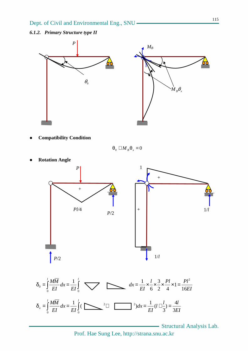
Dept. of Civil and Environmental Eng., SNU
Structural Analysis Lab. Prof. Hae Sung Lee, http://strana.snu.ac.kr
115
6.1.2. Primary Structure type II
Compatibility Condition
00 =θ+θ xBM
Rotation Angle
EI
PlPll
EIdx
EIdx
EI
MM ll
161
42
3
6
1
1 2
00
0 =××××===δ
EI
lll
EIdx
EIdx
EI
MM ll
x 3
4)
3(
1) (
1
0
22
0
=+=+==δ
P
0θ
P
P/2
P/2
Pl/4
+
1
+
+ 1/l
1/l
MB
xBM θ

Dept. of Civil and Environmental Eng., SNU
Structural Analysis Lab. Prof. Hae Sung Lee, http://strana.snu.ac.kr
116
Compatibility condition and the final solution
034
16
2
=+ BMEI
l
EI
Pl → 643Pl
M B −=
6.2 Γ-shaped Frame-II
6.2.1 Primary Structure type I
w
RA
MA
RB
EI,l
HB
EI,l
-wl2/2
M0
-
M2
1
l
+
l
M1
1
+
+

Dept. of Civil and Environmental Eng., SNU
Structural Analysis Lab. Prof. Hae Sung Lee, http://strana.snu.ac.kr
117
EI
wll
wll
EIdx
EIdx
EI
MM ll
6))(
2(
3
1
1 42
00
0110 −=−===δ
EI
wll
wll
EIdx
EIdx
EI
MM ll
8))(
2(
4
1
1 42
00
0220 −=−===δ
EI
lll
llll
EIdx
EIdx
EI
MM ll
3
4)})((
3))(({
1) (
1 3
0
22
0
1111 =+=+==δ
EI
lll
l
EIdx
EIdx
EI
MM ll
2))((
2
1
1 3
00
212112 ====δ=δ
EI
lll
l
EIdx
EIdx
EI
MM ll
3))((
3
1
1 3
0
2
0
2222 ====δ
Compatibility condition (Flexibility Equation)
=++−
=++−→
=δ+δ+δ=δ+δ+δ
0328
023
4
60
0
2
3
1
34
2
3
1
34
22212120
21211110
XEI
lX
EI
l
EI
wl
XEI
lX
EI
l
EI
wl
XX
XX
281
wlX −= ,
7
32
wlX =
Reactions
w
wl/28
4wl/7
3wl2/28
wl/28
3wl/7

Dept. of Civil and Environmental Eng., SNU
Structural Analysis Lab. Prof. Hae Sung Lee, http://strana.snu.ac.kr
118
Moment Diagram
Deflected Shape
6.2.2. Primary Structure type II
-3wl2/28
11wl2/196
-wl2/28
M0
wl2/8

Dept. of Civil and Environmental Eng., SNU
Structural Analysis Lab. Prof. Hae Sung Lee, http://strana.snu.ac.kr
119
EI
wldx
EIdx
EI
MM ll
24
1 3
00
012010 ===δ=δ
EI
ll
EIdx
EIdx
EI
MM ll
3)1)(1(
3
1
1
0
2
0
1111 ====δ
EI
ldx
EIdx
EI
MM ll
6
1
00
212112 ===δ=δ
EI
ldx
EIdx
EI
MM ll
3
2) (
1
0
22
0
2222 =+==δ
Compatibility condition (Flexibility Equation)
=++
=++→
=δ+δ+δ=δ+δ+δ
03
2
624
06324
0
0
21
3
21
3
22212120
21211110
XEI
lX
EI
l
EI
wl
XEI
lX
EI
l
EI
wl
XX
XX
28
3 2
1
wlX −= ,
28
2
2
wlX −=
M1
1
+
M2
1
+
+

Dept. of Civil and Environmental Eng., SNU
Structural Analysis Lab. Prof. Hae Sung Lee, http://strana.snu.ac.kr
120
6.3 Portal Frame subject to Horizontal Load
6.3.1. Primary Structure type I
1
w
M0
-wl2/2
-
EI
w
M2
l
+
+
M3
1
1
+
+
+
M1
-l
-
- -
1
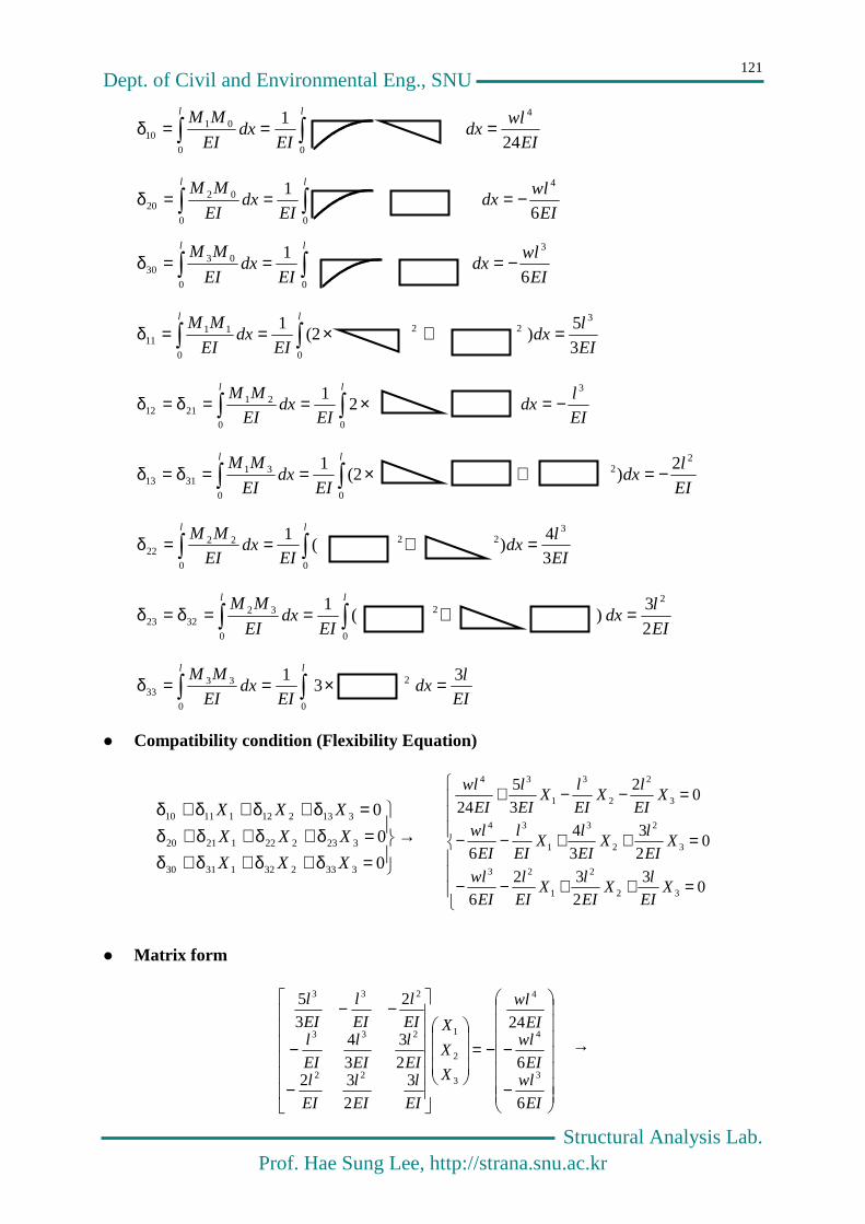
Dept. of Civil and Environmental Eng., SNU
Structural Analysis Lab. Prof. Hae Sung Lee, http://strana.snu.ac.kr
121
EI
wldx
EIdx
EI
MM ll
24
1 4
00
0110 ===δ
EI
wldx
EIdx
EI
MM ll
6
1 4
00
0220 −===δ
EI
wldx
EIdx
EI
MM ll
6
1 3
00
0330 −===δ
EI
ldx
EIdx
EI
MM ll
3
5) (2
1 3
0
22
0
1111 =+×==δ
EI
ldx
EIdx
EI
MM ll 3
00
212112 2
1 −=×==δ=δ
EI
ldx
EIdx
EI
MM ll 2
0
2
0
313113
2) (2
1 −=+×==δ=δ
EI
ldx
EIdx
EI
MM ll
3
4) (
1 3
0
22
0
2222 =+==δ
EI
ldx
EIdx
EI
MM ll
2
3 ) (
1 2
0
2
0
323223 =+==δ=δ
EI
ldx
EIdx
EI
MM ll 3 3
1
0
2
0
3333 =×==δ
Compatibility condition (Flexibility Equation)
→
=δ+δ+δ+δ=δ+δ+δ+δ
=δ+δ+δ+δ
0
0
0
33323213130
32322212120
31321211110
XXX
XXX
XXX
=++−−
=++−−
=−−+
03
232
6
02
3
3
4
6
02
3
5
24
32
2
1
23
3
2
2
3
1
34
3
2
2
3
1
34
XEI
lX
EI
lX
EI
l
EI
wl
XEI
lX
EI
lX
EI
l
EI
wl
XEI
lX
EI
lX
EI
l
EI
wl
Matrix form
−
−−=
−
−
−−
EI
wlEI
wlEI
wl
X
X
X
EI
l
EI
l
EI
lEI
l
EI
l
EI
lEI
l
EI
l
EI
l
6
6
24
3
2
322
3
3
4
2
3
5
3
4
4
3
2
1
22
233
233
→

Dept. of Civil and Environmental Eng., SNU
Structural Analysis Lab. Prof. Hae Sung Lee, http://strana.snu.ac.kr
122
=
−
−
−
−
−−
−=
−
252
317
24
5
6
6
24
3
2
322
3
3
4
2
3
5
23
4
41
22
233
233
3
2
1
wl
wl
wl
EI
wlEI
wlEI
wl
EI
l
EI
l
EI
lEI
l
EI
l
EI
lEI
l
EI
l
EI
l
X
X
X
Reactions
Moment Diagram
Deflected Shape
w
5wl/24 19wl/24
wl /7 wl /7
59wl2/252
31wl2/252
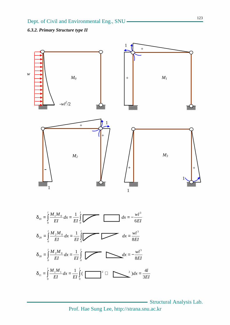
Dept. of Civil and Environmental Eng., SNU
Structural Analysis Lab. Prof. Hae Sung Lee, http://strana.snu.ac.kr
123
6.3.2. Primary Structure type II
EI
wldx
EIdx
EI
MM ll
6
1 3
00
0110 −===δ
EI
wldx
EIdx
EI
MM ll
8
1 3
00
0220 ===δ
EI
wldx
EIdx
EI
MM ll
8
1 3
00
0330 −===δ
EI
ldx
EIdx
EI
MM ll
3
4) (
1
0
22
0
1111 =+==δ
1
1 +
+ M1
+
+
-
1
M2
+ +
1
1
M3
M0 w
-wl2/2

Dept. of Civil and Environmental Eng., SNU
Structural Analysis Lab. Prof. Hae Sung Lee, http://strana.snu.ac.kr
124
21
00
2112 3
) (1 δ=−=+==δ EI
ldx
EIdx
EI
MM ll
31
00
3113 2
1 δ====δ EI
ldx
EIdx
EI
MM ll
EI
ldx
EIdx
EI
MM ll
=×==δ 0
2
0
2222 3
1
32
00
3223 6
) (1 δ=−=+==δ EI
ldx
EIdx
EI
MM ll
EI
ldx
EIdx
EI
MM ll
3
2 2
1
0
2
0
3333 =×==δ
Compatibility condition (Flexibility Equation)
0
0
0
33323213130
32322212120
31321211110
=δ+δ+δ+δ=δ+δ+δ+δ
=δ+δ+δ+δ
XXX
XXX
XXX
Matrix Form
−
−
−=
−
−−
−
EI
wlEI
wlEI
wl
X
X
X
EI
l
EI
l
EI
lEI
l
EI
l
EI
lEI
l
EI
l
EI
l
8
8
6
3
2
62
63
233
4
3
3
3
3
2
1
−=
−
−
−
−
−=
−
−
−
−−
−
−=
−
252
31504
43504
29
8
8
6
21
44
21
2
21
1621
2
21
23
21
521
16
21
5
21
23
8
8
6
3
2
62
63
233
4
2
3
3
3
3
3
31
3
2
1
wl
EI
wlEI
wlEI
wl
l
EI
EI
wlEI
wlEI
wl
EI
l
EI
l
EI
lEI
l
EI
l
EI
lEI
l
EI
l
EI
l
X
X
X

Dept. of Civil and Environmental Eng., SNU
Structural Analysis Lab. Prof. Hae Sung Lee, http://strana.snu.ac.kr
125
6.4 Portal Frame subject to Vertical Load
1
1 +
+ M1
+
+
-
1
M2
+ +
1
1
M3
EI,l
a P
M0
l
Pab

Dept. of Civil and Environmental Eng., SNU
Structural Analysis Lab. Prof. Hae Sung Lee, http://strana.snu.ac.kr
126
l
ba
EI
Pab
l
Pab
l
bldx
EIdx
EI
MM ll 2
61)1(
6
1
00
0110
+=××+===δ
l
ba
EI
Pab
l
Pab
l
aldx
EIdx
EI
MM ll +=××+===δ 2
61)1(
6
1
00
0220
00
0330 ==δ
l
dxEI
MM
Matrix Form
−−
+
+
−=
+
+
−
−
−=
ba
ba
ba
l
Pab
l
bal
ba
l
Pab
X
X
X
104
1117
1711
42
0
2
2
21
44
21
2
21
16212
2123
215
2116
215
2123
6 2
3
2
1
Sidesway : )(28
1ab
EI
Pab −=∆
Deflected Shape
4
la =

Dept. of Civil and Environmental Eng., SNU
Structural Analysis Lab. Prof. Hae Sung Lee, http://strana.snu.ac.kr
127
6.5 Order of Indeterminacy
# of unknowns
# of member × # of internal force per member +
# of reactions - # of known quantities
# of equations
# of member × # of E.E. per member +
# of joints × # of E.E. per joint - # of used equations
# of Indeterminacy = # of unknowns - # of equations
Order of Indeterminacy of the frame shown above
6×10 +3×3 – (3×10 +3×9) = 69 – 57 = 12
6.5.1. Order of Indeterminacy – Beam
Number of Internal Forces in a Member : 4
Number of Equilibrium Equations in a Member : 2
Number of Equilibrium Equations at a Joint : 2
Simple Beam
- # of unknowns : 4×1 + 1×2 = 6 or 4×1 + 2×2 – 2= 6
- # of equations : 2×1 + 2×2 = 6

Dept. of Civil and Environmental Eng., SNU
Structural Analysis Lab. Prof. Hae Sung Lee, http://strana.snu.ac.kr
128
- Order of Indeterminacy : 6 – 6 = 0
Overhanged Beam
- # of unknowns : 4×2 + 1×2 – 2 = 8
- # of equations : 2×2 + 2×2 = 8
- Order of Indeterminacy : 8 – 8 = 0
Gerber Beam
- # of unknowns : 4×3 + 1×3 – 2 = 13
- # of equations : 2×3 + 2×4 – 1= 13
- Order of Indeterminacy : 13 – 13 = 0
Continuous Beam
- # of unknowns : 4×3 + 1×4 = 16
- # of equations : 2×3 + 2×4 = 14
- Order of Indeterminacy : 16 – 14 = 2
6.5.2. Order of Indeterminacy - Truss
Number of Internal Forces in a Member : 1
Number of Equilibrium Equations in a Member : 0
Number of Equilibrium Equations at a Joint : 2

Dept. of Civil and Environmental Eng., SNU
Structural Analysis Lab. Prof. Hae Sung Lee, http://strana.snu.ac.kr
129
Determinate Truss
- # of unknowns : 1×21 + 3 = 24
- # of equations : 2×12 = 24
- Order of Indeterminacy : 24 – 24 = 0
Internally Indeterminate Truss
- # of unknowns : 1×25 + 3 = 28
- # of equations : 2×12 = 24
- Order of Indeterminacy : 28 – 24 = 4
Internally Indeterminate Truss
- # of unknowns : 1×25 + 5 = 30
- # of equations : 2×12 = 24
- Order of Indeterminacy : 30 – 24 = 6

Dept. of Civil and Environmental Eng., SNU
Structural Analysis Lab. Prof. Hae Sung Lee, http://strana.snu.ac.kr
130
6.5.3. Order of Indeterminacy - Frame
Number of Internal Forces in a Member : 6
Number of Equilibrium Equations in a Member : 3
Number of Equilibrium Equations at a Joint : 3
Internally Indeterminate Frame
- # of unknowns : 6×3 + 3 = 21
- # of equations : 3×3 + 3×4 = 21
- Order of Indeterminacy : 21 – 21 = 0
Frame with Hinges
- # of unknowns : 6×4 + 4 – 2 = 26
- # of equations : 3×4 + 3×5 – 1 = 26
- Order of Indeterminacy : 26 – 26 = 0
Portal Frame with Fixed Supports
- # of unknowns : 6×3 + 6 = 24
- # of equations : 3×3 + 3×4 = 21
- Order of Indeterminacy : 24 – 21 = 3

Dept. of Civil and Environmental Eng., SNU
Structural Analysis Lab. Prof. Hae Sung Lee, http://strana.snu.ac.kr
131
6.5.4. Selecting a Primary Structure for a Complicated Frame
Order of Indeterminacy of the frame
- # of unknowns : 6×10 + 3×3 = 69
- # of equations : 3×10 + 3×9 = 57
- Order of Indeterminacy : 69 – 57 = 12
By Replacing a Rigid Joint with a Hinge, we can reduce
- # of unknowns by the number of members at the joint
- # of equations by one
In the Primary Structure
- Reduction in unknowns : 1 + 1 + 3 + 4 + 3 + 2 + 3 = 19
- Reduction in equations : 5
- Reduction in Indeterminacy : 17 – 5 = 12

Dept. of Civil and Environmental Eng., SNU
Structural Analysis Lab. Prof. Hae Sung Lee, http://strana.snu.ac.kr
132
6.6 General Frame
Primary Structure
M1, M2, M3
EI
L
L/2
2EI
q qL
EI
L L
EI
ql2/8 4
2ql
M0
M1 M2
M3
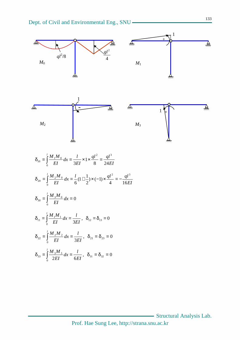
Dept. of Civil and Environmental Eng., SNU
Structural Analysis Lab. Prof. Hae Sung Lee, http://strana.snu.ac.kr
133
EI
qlql
EI
ldx
EI
MMl
2481
3
32
0
0110 =××==δ
EI
qlqlldx
EI
MMl
164)1()
2
11(
6
32
0
0220 −=×−×+==δ
00
0330 ==δ
l
dxEI
MM
EI
ldx
EI
MMl
30
1111 ==δ , 01312 =δ=δ
EI
ldx
EI
MMl
30
2222 ==δ , 02321 =δ=δ
EI
ldx
EI
MMl
620
3333 ==δ , 03231 =δ=δ
ql2/8 4
2ql
+ 1
- 1
+ 1
M0 M1
M2 M3

Dept. of Civil and Environmental Eng., SNU
Structural Analysis Lab. Prof. Hae Sung Lee, http://strana.snu.ac.kr
134
Compatibility Condition
321 δ=δ=δ
1
3
313212111101 324M
EI
l
EI
qlMMM +=δ+δ+δ+δ=δ
2
3
323222121202 316M
EI
l
EI
qlMMM +−=δ+δ+δ+δ=δ
3333232131303 6M
EI
lMMM =δ+δ+δ+δ=δ
One Additional Equilibrium Equation
0321 =++ MMM → 213 MMM −−=
Final Compatibility Condition
062246324 21
3
31
3
=++=−+ MEI
lM
EI
l
EI
qlM
EI
lM
EI
l
EI
ql
026166316 21
3
32
3
=++−=−+− MEI
lM
EI
l
EI
qlM
EI
lM
EI
l
EI
ql
21 64
9qlM −= , 2
2 64
11qlM = , 2
3 64
2qlM −=
In case n members are connected to a joint, and a hinge is used to release moment at the
joint you, have n-1 compatibility equations and one equilibrium equation, which leads to
total of n-1 compatibility equations with n-1 unknowns.

Dept. of Civil and Environmental Eng., SNU
Structural Analysis Lab. Prof. Hae Sung Lee, http://strana.snu.ac.kr
135
6.7 General Joint Compatibility
Compatibility Condition
nδ==δ=δ L21
j
k
njijj
n
jijii MM
+==
δ+δ+δ=δ11
0 ni L1for =
One Additional Equilibrium Equation
021 =+++ nMMM L
Joint i
M1
Mn

Dept. of Civil and Environmental Eng., SNU
Structural Analysis Lab. Prof. Hae Sung Lee, http://strana.snu.ac.kr
136
This page is intentionally left blank.

Dept. of Civil and Environmental Eng., SNU
Structural Analysis Lab. Prof. Hae Sung Lee, http://strana.snu.ac.kr
137
Chapter 7
Influence Lines for
Determinate Structures

Dept. of Civil and Environmental Eng., SNU
Structural Analysis Lab. Prof. Hae Sung Lee, http://strana.snu.ac.kr
138
7.1 Influence Function
Influence function
Convolution integral – Superposition
ξξξ= dqxIxdR pp )(),()(
ξξξ=l
pp dqxIxR0
)(),()(
Dirac delta functions
0lim→ε
= = )( ξ−δ x
122
1lim)0
2
10(lim)(
00
00
=εε
=+ε
+=ξ−δ→ε
ε+ξ
ε+ξ
ε−ξ
ε−ξ
→ε ll
dxdxdxdxx
)()(2
)()(lim)(
2
1lim
)0)(2
1)(0)((lim)()(
00
00
0
ξ=ξ′=ε
ε−ξ−ε+ξ=ε
=
+ε
+=ξ−δ
→ε
ε+ξ
ε−ξ→ε
ε+ξ
ε+ξ
ε−ξ
ε−ξ
→ε
fFFF
dxxf
dxxfdxxfdxxfdxxxfll
ξ
∞
ξ
ε2
1
2ε
1 ξ
I(xp,ξ)
xp
ξ q(x)
R(xp)
q(ξ)dξ
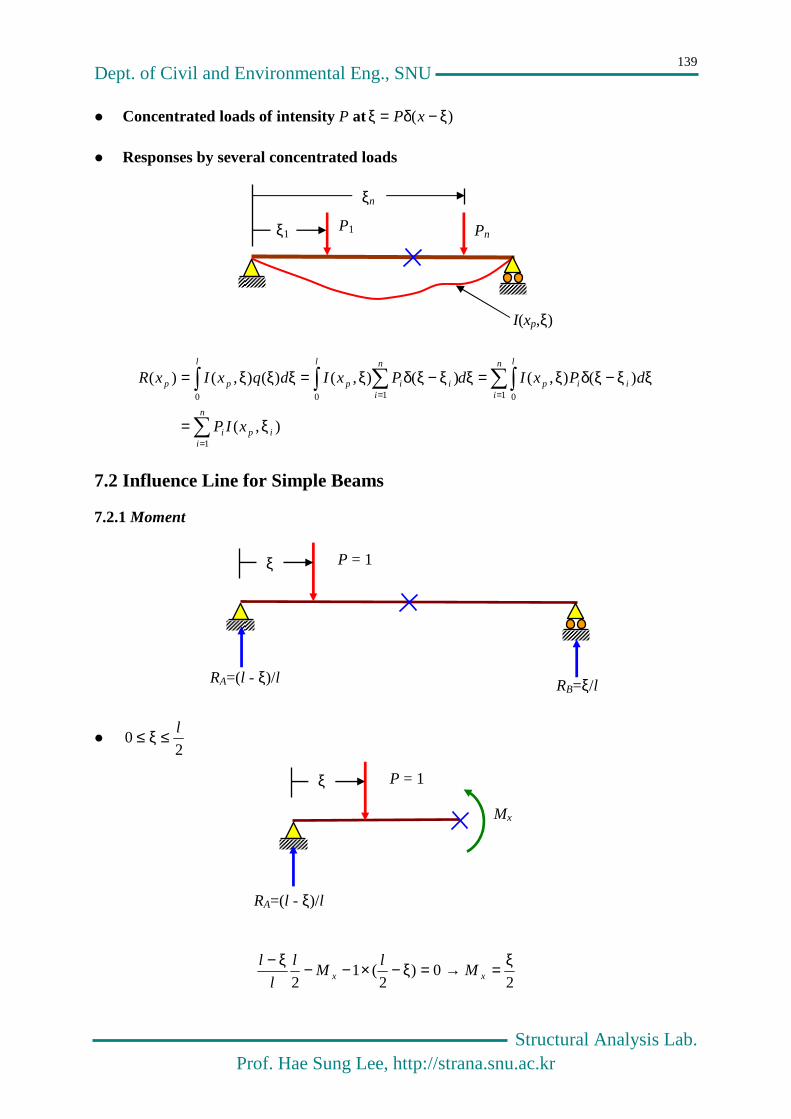
Dept. of Civil and Environmental Eng., SNU
Structural Analysis Lab. Prof. Hae Sung Lee, http://strana.snu.ac.kr
139
Concentrated loads of intensity P at )( ξ−δ=ξ xP
Responses by several concentrated loads
=
==
ξ=
ξξ−ξδξ=ξξ−ξδξ=ξξξ=
n
iipi
n
i
l
iip
l n
iiip
l
pp
xIP
dPxIdPxIdqxIxR
1
1 00 10
),(
)(),()(),()(),()(
7.2 Influence Line for Simple Beams
7.2.1 Moment
20
l≤ξ≤
2
0)2
(12
ξ=→=ξ−×−−ξ−xx M
lM
l
l
l
P1 ξ1
I(xp,ξ)
ξn
Pn
RA=(l - ξ)/l
ξ
RB=ξ/l
P = 1
RA=(l - ξ)/l
ξ P = 1 Mx

Dept. of Civil and Environmental Eng., SNU
Structural Analysis Lab. Prof. Hae Sung Lee, http://strana.snu.ac.kr
140
ll ≤ξ≤2
2
02
ξ−=→=−ξ− lMM
l
l
lxx
Influence line
7.2.2. Shear Force
20
l≤ξ≤
lVV
l
lxx
ξ−=→=++ξ−− 01
RA=(l - ξ)/l
ξ P = 1
Vx
RA=(l - ξ)/l
ξ
RB=ξ/l
P = 1
+ L/4
RA=(l - ξ)/l
Mx
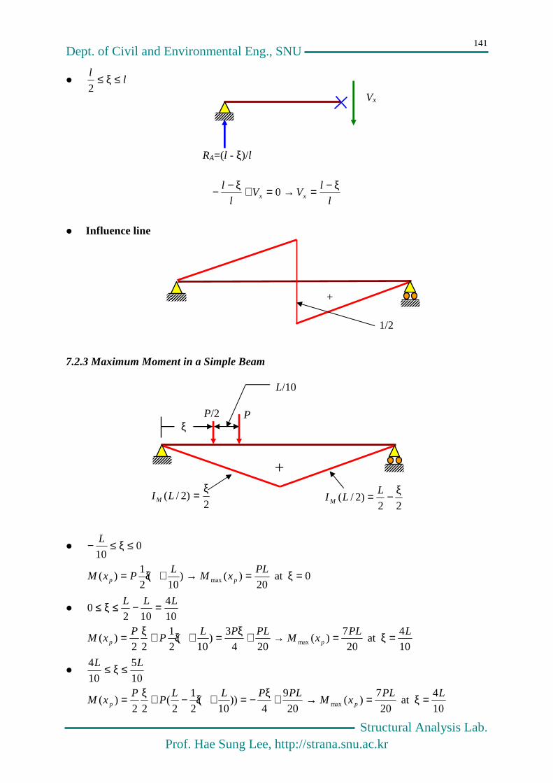
Dept. of Civil and Environmental Eng., SNU
Structural Analysis Lab. Prof. Hae Sung Lee, http://strana.snu.ac.kr
141
ll ≤ξ≤2
l
lVV
l
lxx
ξ−=→=+ξ−− 0
Influence line
7.2.3 Maximum Moment in a Simple Beam
010
≤ξ≤− L
0at 20
)()10
(2
1)( max =ξ=→+ξ= PL
xML
PxM pp
10
4
1020
LLL =−≤ξ≤
10
4at
20
7)(
204
3)
10(
2
1
22)( max
LPLxM
PLPLP
PxM pp =ξ=→+ξ=+ξ+ξ=
10
5
10
4 LL ≤ξ≤
10
4at
20
7)(
20
9
4))
10(
2
1
2(
22)( max
LPLxM
PLPLLP
PxM pp =ξ=→+ξ−=+ξ−+ξ=
RA=(l - ξ)/l
Vx
+
1/2
+
P/2 ξ
P
L/10
2)2/(
ξ=LIM22
)2/(ξ−= L
LI M
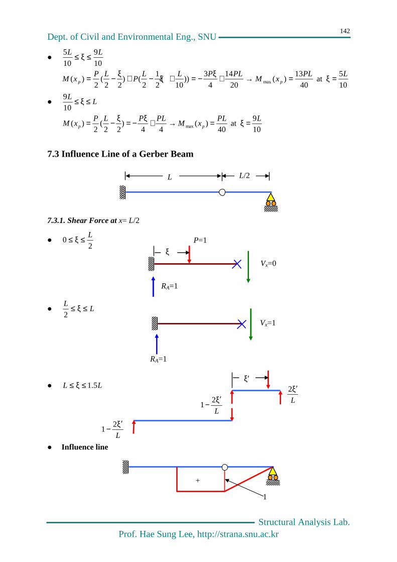
Dept. of Civil and Environmental Eng., SNU
Structural Analysis Lab. Prof. Hae Sung Lee, http://strana.snu.ac.kr
142
10
9
10
5 LL ≤ξ≤
10
5at
40
13)(
20
14
4
3))
10(
2
1
2()
22(
2)( max
LPLxM
PLPLLP
LPxM pp =ξ=→+ξ−=+ξ−+ξ−=
LL ≤ξ≤
10
9
10
9at
40)(
44)
22(
2)( max
LPLxM
PLPLPxM pp =ξ=→+ξ−=ξ−=
7.3 Influence Line of a Gerber Beam
7.3.1. Shear Force at x= L/2
20
L≤ξ≤
LL ≤ξ≤2
LL 5.1≤ξ≤
Influence line
ξ′
L
ξ′2
L
ξ′− 2
1
L
ξ′− 2
1
L/2 L
RA=1
ξ P=1
Vx=0
RA=1
Vx=1
+
1

Dept. of Civil and Environmental Eng., SNU
Structural Analysis Lab. Prof. Hae Sung Lee, http://strana.snu.ac.kr
143
7.3.2. Moment at the fixed end
L≤ξ≤0
LL 5.1≤ξ≤
Influence line
7.3.1 Maximum Moment at the fixed end
+ξ
ξ
+ξ
ξ
==ξ4/4/
)()()(L
M
L
M dxxIqdxxqIM
– L4
30 ≤ξ≤
)4
2(84
)4
(2
1)(
LqLLLqM +ξ−=+ξ+ξ×−=ξ → 22
max 2188.032
7qLqLM −=−=
-
L
)23()2( ξ−−=ξ′−− LL −ξ
-
L
L/4
ξ
ξ ξ−=xM
)2( ξ′−−= LM x
ξ′
L
ξ′2
L
ξ′− 2
1
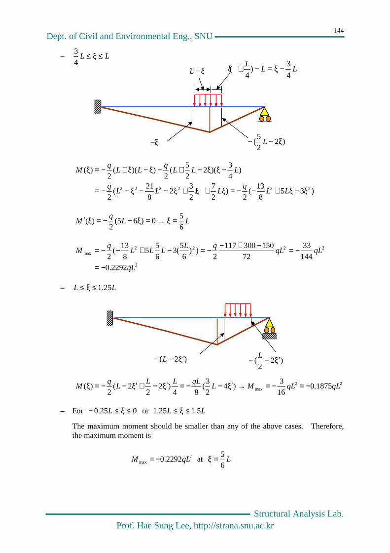
Dept. of Civil and Environmental Eng., SNU
Structural Analysis Lab. Prof. Hae Sung Lee, http://strana.snu.ac.kr
144
– LL ≤ξ≤4
3
)358
13(
2)
2
7
2
32
8
21(
2
)4
3)(2
2
5(
2))((
2)(
222222 ξ−ξ+−−=ξ+ξ+ξ−−ξ−−=
−ξξ−+−ξ−ξ+−=ξ
LLq
LLLLq
LLLq
LLq
M
LLq
M6
50)65(
2)( =ξ→=ξ−−=ξ′
2
2222max
2292.0
144
33
72
150300117
2))
6
5(3
6
55
8
13(
2
qL
qLqLqL
LLLq
M
−=
−=−+−−=−+−−=
– LL 25.1≤ξ≤
22max 1875.0
16
3)4
2
3(
84)2
22(
2)( qLqLML
qLLLL
qM −=−=→ξ′−−=ξ′−+ξ′−−=ξ
– For 025.0 ≤ξ≤− L or LL 5.125.1 ≤ξ≤
The maximum moment should be smaller than any of the above cases. Therefore, the maximum moment is
2max 2292.0 qLM −= at L
6
5=ξ
)2( ξ′−− L )22
( ξ′−− L
)22
5( ξ−− L −ξ
ξ−L LLL
4
3)
4( −ξ=−+ξ

Dept. of Civil and Environmental Eng., SNU
Structural Analysis Lab. Prof. Hae Sung Lee, http://strana.snu.ac.kr
145
7.4 Indirect Load
Equivalent to
10 =+→= bav RRF
0)22
()22
)(1(0 0
0
0
0
=−++−−→= lRll
l
xll
l
xM ba
l
x
l
llRb +−=
20 ,
l
x
l
llRR ba −
+=−=
21 0
In case the unit load is applied directly on the simple beam,
10 =+→= bav RRF
0)22
(0 0 =−+−→= lRxll
M ba
Ra Rb
l0
1-x/l0 x/l0
l
Ra Rb
x
l0
l/2
P =1
l
Ra Rb
x (l-l0)/2
l/2
P =1

Dept. of Civil and Environmental Eng., SNU
Structural Analysis Lab. Prof. Hae Sung Lee, http://strana.snu.ac.kr
146
l
x
l
llRb +−=
20
,
l
x
l
llRR ba −+=−=
21 0 (Statically equivalent to the indirect load)
0)2
)(2
()1(0 00
0
=ξ+−
−+
+ξ−−−→= ξll
l
x
l
ll
l
xMM
ξ−−
+−
−+
=ξ+−
−+
+ξ−−= )12
(22
)2
()2
)(2
()1(0
00000
0 l
x
l
llll
l
x
l
llll
l
x
l
ll
l
xM
7.4.1 Influence line at the mid-span
422222)1
2(
22)
2( 000000
0
000 lll
l
llll
l
lll
l
x
l
llll
l
x
l
llM
−=
−−
−+=−
−+
−−
+=
7.5 Influence Line of Truss
7.5.1 Truss Case
Ra Rb
1-x/l0 x/l0
ξ
Ra Rb
1-x/l0 x/l0
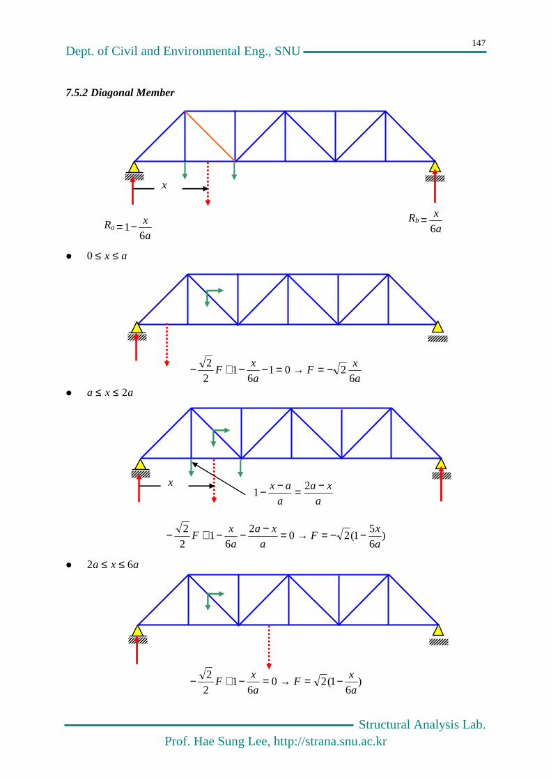
Dept. of Civil and Environmental Eng., SNU
Structural Analysis Lab. Prof. Hae Sung Lee, http://strana.snu.ac.kr
147
Raa
x
61−=
Rba
x
6=
x
7.5.2 Diagonal Member
ax ≤≤0
a
xF
a
xF
6201
61
22 −=→=−−+−
axa 2≤≤
)65
1(202
61
22
a
xF
a
xa
a
xF −−=→=−−−+−
axa 62 ≤≤
)6
1(206
122
a
xF
a
xF −=→=−+−
x
a
xa
a
ax −=−− 21
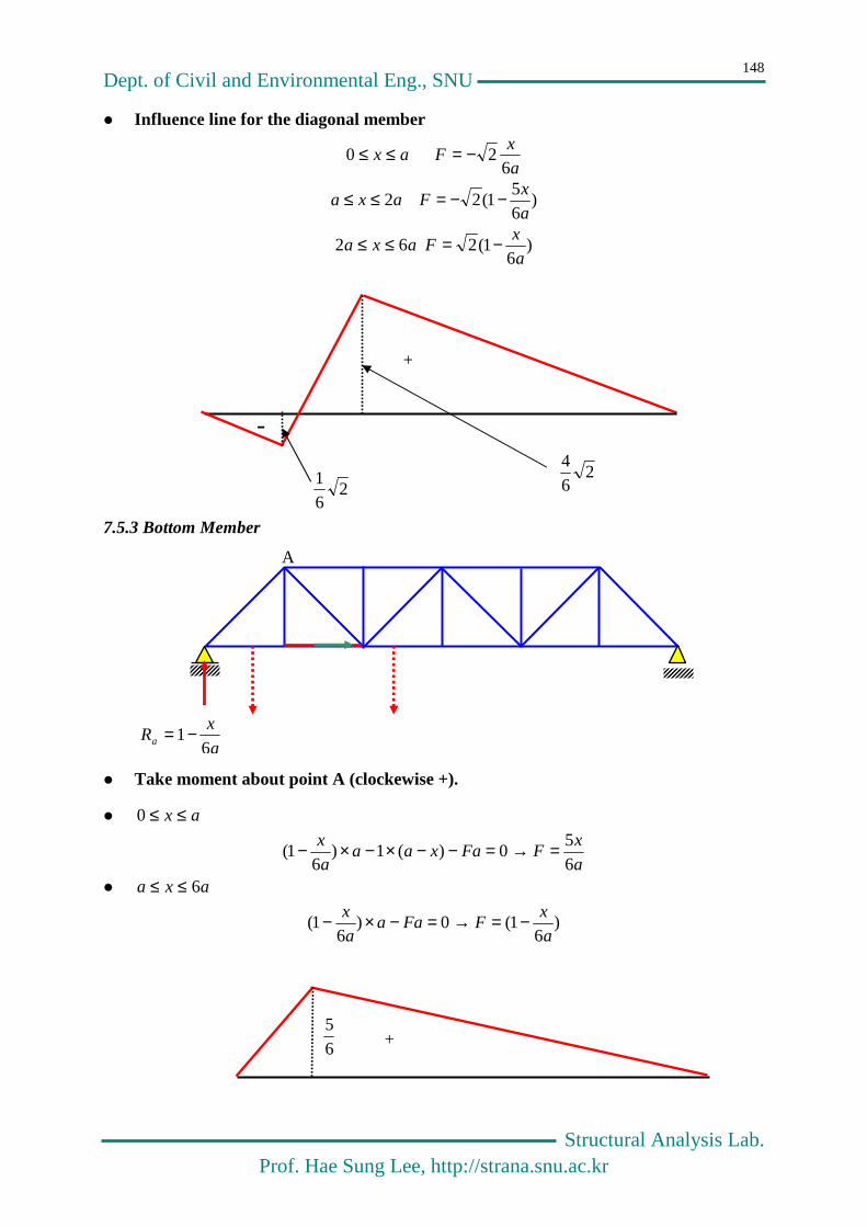
Dept. of Civil and Environmental Eng., SNU
Structural Analysis Lab. Prof. Hae Sung Lee, http://strana.snu.ac.kr
148
Influence line for the diagonal member
a
xFax
62 0 −=≤≤
)65
1(2 2a
xFaxa −−=≤≤
)6
1(2 62a
xFaxa −=≤≤
7.5.3 Bottom Member
Take moment about point A (clockewise +).
ax ≤≤0
a
xFFaxaa
a
x
65
0)(1)6
1( =→=−−×−×−
axa 6≤≤ )
61(0)
61(
a
xFFaa
a
x −=→=−×−
+
-
264
2
61
a
xRa 6
1−=
A
65
+