Embed Size (px)
Citation preview

A N A M E R I C A N N A T I O N A L S T A N D A R D
ASME B107.410-2018(Revision of ASME B107.410-2008)
Struck Tools
falatghareh.irfalatghareh.ir

ASME B107.410-2018(Revision of ASME B107.410-2008)
Struck Tools
AN AMERICAN NATIONAL STANDARD
x
falatghareh.irfalatghareh.ir

Date of Issuance: January 25, 2019
This Standard will be revised when the Society approves the issuance of a new edition.
ASME issues written replies to inquiries concerning interpretations of technical aspects of this Standard. Interpretations arepublishedon theCommitteewebpageandunderhttp://go.asme.org/InterpsDatabase. Periodically certain actionsof theASMEB107 Committee may be published as Cases. Cases are published on the ASME website under the B107 Committee Page athttp://go.asme.org/B107committee as they are issued.
Errata to codes and standards may be posted on the ASME website under the Committee Pages to provide corrections toincorrectly published items, or to correct typographical or grammatical errors in codes and standards. Such errata shall be usedon the date posted.
The B107 Committee Page can be found at http://go.asme.org/B107committee. There is an option available to automaticallyreceive an e-mail notification when errata are posted to a particular code or standard. This option can be found on theappropriate Committee Page after selecting “Errata” in the “Publication Information” section.
ASME is the registered trademark of The American Society of Mechanical Engineers.
This code or standardwas developed under procedures accredited asmeeting the criteria for American National Standards. The StandardsCommittee that approved the code or standardwas balanced to assure that individuals from competent and concerned interests have had anopportunity to participate. The proposed code or standard was made available for public review and comment that provides an opportunityfor additional public input from industry, academia, regulatory agencies, and the public-at-large.
ASME does not “approve,” “rate,” or “endorse” any item, construction, proprietary device, or activity.ASME does not take any position with respect to the validity of any patent rights asserted in connection with any items mentioned in this
document, and does not undertake to insure anyone utilizing a standard against liability for infringement of any applicable letters patent, norassumeany such liability. Usersof a codeor standardare expressly advised thatdeterminationof the validity of any suchpatent rights, and therisk of infringement of such rights, is entirely their own responsibility.
Participation by federal agency representative(s) or person(s) affiliated with industry is not to be interpreted as government or industryendorsement of this code or standard.
ASME accepts responsibility for only those interpretations of this document issued in accordance with the established ASME proceduresand policies, which precludes the issuance of interpretations by individuals.
No part of this document may be reproduced in any form,in an electronic retrieval system or otherwise,
without the prior written permission of the publisher.
The American Society of Mechanical EngineersTwo Park Avenue, New York, NY 10016-5990
Copyright © 2019 byTHE AMERICAN SOCIETY OF MECHANICAL ENGINEERS
All rights reservedPrinted in U.S.A.
falatghareh.irfalatghareh.ir

CONTENTS
Foreword . . . . . . . . . . . . . . . . . . . . . . . . . . . . . . . . . . . . . . . . . . . . . . . . . . . . . . . . . . . . . . . . . . . . . . . . v
Committee Roster . . . . . . . . . . . . . . . . . . . . . . . . . . . . . . . . . . . . . . . . . . . . . . . . . . . . . . . . . . . . . . . . . . vi
Correspondence With the B107 Committee . . . . . . . . . . . . . . . . . . . . . . . . . . . . . . . . . . . . . . . . . . . . . . . . vii
1 Scope . . . . . . . . . . . . . . . . . . . . . . . . . . . . . . . . . . . . . . . . . . . . . . . . . . . . . . . . . . . . . . . . . . 12 Definitions . . . . . . . . . . . . . . . . . . . . . . . . . . . . . . . . . . . . . . . . . . . . . . . . . . . . . . . . . . . . . . 13 References . . . . . . . . . . . . . . . . . . . . . . . . . . . . . . . . . . . . . . . . . . . . . . . . . . . . . . . . . . . . . . 64 Classification . . . . . . . . . . . . . . . . . . . . . . . . . . . . . . . . . . . . . . . . . . . . . . . . . . . . . . . . . . . . 65 Performance Requirements . . . . . . . . . . . . . . . . . . . . . . . . . . . . . . . . . . . . . . . . . . . . . . . . . 66 Tests . . . . . . . . . . . . . . . . . . . . . . . . . . . . . . . . . . . . . . . . . . . . . . . . . . . . . . . . . . . . . . . . . . 257 Safety Requirements and Limitations of Use . . . . . . . . . . . . . . . . . . . . . . . . . . . . . . . . . . . . 41
Figures5.1-1 Category 43 Wood-Splitting Wedges . . . . . . . . . . . . . . . . . . . . . . . . . . . . . . . . . . . . . . . . . . . . 95.1-2 Category 43 Square Head Wedges . . . . . . . . . . . . . . . . . . . . . . . . . . . . . . . . . . . . . . . . . . . . . . 95.1-3 Category 43 Stave and Oregon-Splitting Wedges . . . . . . . . . . . . . . . . . . . . . . . . . . . . . . . . . . . 95.2-1 Category 44 Glaziers’ Chisels . . . . . . . . . . . . . . . . . . . . . . . . . . . . . . . . . . . . . . . . . . . . . . . . . 105.2-2 Category 44 All-Steel Wood Chisels . . . . . . . . . . . . . . . . . . . . . . . . . . . . . . . . . . . . . . . . . . . . . 105.2-3 Category 44 Wood Chisels . . . . . . . . . . . . . . . . . . . . . . . . . . . . . . . . . . . . . . . . . . . . . . . . . . . 115.2-4 Category 44 Ripping Chisels . . . . . . . . . . . . . . . . . . . . . . . . . . . . . . . . . . . . . . . . . . . . . . . . . . 125.2-5 Category 44 Flooring/Electricians’ Chisels . . . . . . . . . . . . . . . . . . . . . . . . . . . . . . . . . . . . . . . . 135.3-1 Category 46 Multi-Spline Extractor . . . . . . . . . . . . . . . . . . . . . . . . . . . . . . . . . . . . . . . . . . . . . 145.3-2 Category 46 Spiral Flute Extractor . . . . . . . . . . . . . . . . . . . . . . . . . . . . . . . . . . . . . . . . . . . . . 145.3-3 Category 46 Straight Flute Extractor . . . . . . . . . . . . . . . . . . . . . . . . . . . . . . . . . . . . . . . . . . . . 155.3-4 Category 46 Tapered Flute Extractor . . . . . . . . . . . . . . . . . . . . . . . . . . . . . . . . . . . . . . . . . . . . 155.4.1-1 Category 48 Type I Chisels . . . . . . . . . . . . . . . . . . . . . . . . . . . . . . . . . . . . . . . . . . . . . . . . . . . 165.4.1-2 Category 48 Type I Handle-Held Chisels . . . . . . . . . . . . . . . . . . . . . . . . . . . . . . . . . . . . . . . . . 165.4.2-1 Category 48 Type II Punches . . . . . . . . . . . . . . . . . . . . . . . . . . . . . . . . . . . . . . . . . . . . . . . . . 175.4.2-2 Category 48 Type II Handle-Held Punches . . . . . . . . . . . . . . . . . . . . . . . . . . . . . . . . . . . . . . . . 185.4.3-1 Category 48 Type III Drift Pins . . . . . . . . . . . . . . . . . . . . . . . . . . . . . . . . . . . . . . . . . . . . . . . . 185.5.1-1 Category 49 Type I Nail Set . . . . . . . . . . . . . . . . . . . . . . . . . . . . . . . . . . . . . . . . . . . . . . . . . . 195.5.2-1 Category 49 Type II (Self-Centering) Nail Set . . . . . . . . . . . . . . . . . . . . . . . . . . . . . . . . . . . . . . 195.6-1 Category 50 Brick Chisel and Brick Set . . . . . . . . . . . . . . . . . . . . . . . . . . . . . . . . . . . . . . . . . . 205.6-2 Configuration of Category 50 Brick Chisel and Brick Set Bevels . . . . . . . . . . . . . . . . . . . . . . . . 205.6-3 Category 50 Star Drill . . . . . . . . . . . . . . . . . . . . . . . . . . . . . . . . . . . . . . . . . . . . . . . . . . . . . . 215.7.1-1 Category 52 Type I Struck Nail-Puller Bars . . . . . . . . . . . . . . . . . . . . . . . . . . . . . . . . . . . . . . . 225.7.1-2 Category 52 Type II, Class 1 Nonstruck Multipurpose Bar . . . . . . . . . . . . . . . . . . . . . . . . . . . . 235.7.1-3 Category 52 Type II, Class 2 Nonstruck Ripping/Wrecking Bar . . . . . . . . . . . . . . . . . . . . . . . . . 235.7.2-1 Category 52 Type III, Class 1 Close Quarter Pry Bar . . . . . . . . . . . . . . . . . . . . . . . . . . . . . . . . . 23
iii
falatghareh.irfalatghareh.ir
5.7.3-1 Category 52 Type III, Class 2 Die Setter Pry Bar . . . . . . . . . . . . . . . . . . . . . . . . . . . . . . . . . . . 235.7.4-1 Category 52 Type III, Class 3 Handled Pry Bar . . . . . . . . . . . . . . . . . . . . . . . . . . . . . . . . . . . . . 235.7.5-1 Category 52 Type III, Class 4 Pinch Bar . . . . . . . . . . . . . . . . . . . . . . . . . . . . . . . . . . . . . . . . . . 235.7.6-1 Category 52 Type III, Class 5 Rolling Head Pry Bar . . . . . . . . . . . . . . . . . . . . . . . . . . . . . . . . . 245.8-1 Category 59 Striking Wrenches . . . . . . . . . . . . . . . . . . . . . . . . . . . . . . . . . . . . . . . . . . . . . . . . 245.8-2 Category 59 Slugging Wrenches . . . . . . . . . . . . . . . . . . . . . . . . . . . . . . . . . . . . . . . . . . . . . . . 245.8-3 Struck Block Cross Section . . . . . . . . . . . . . . . . . . . . . . . . . . . . . . . . . . . . . . . . . . . . . . . . . . . 246.2.2-1 Impact Test for Category 44 Types I and II Chisels . . . . . . . . . . . . . . . . . . . . . . . . . . . . . . . . . 306.2.8-1 Category 52 Handle Impact Test . . . . . . . . . . . . . . . . . . . . . . . . . . . . . . . . . . . . . . . . . . . . . . . 336.2.9.1-1 Impact Test Setup . . . . . . . . . . . . . . . . . . . . . . . . . . . . . . . . . . . . . . . . . . . . . . . . . . . . . . . . . 346.4-1 Category 44 Side Force Test . . . . . . . . . . . . . . . . . . . . . . . . . . . . . . . . . . . . . . . . . . . . . . . . . . 356.5.1-1 Category 44 Permanent Set Test . . . . . . . . . . . . . . . . . . . . . . . . . . . . . . . . . . . . . . . . . . . . . . . 366.6-1 Category 48 Bending Moment Test . . . . . . . . . . . . . . . . . . . . . . . . . . . . . . . . . . . . . . . . . . . . . 366.7-1 Static Force Test for Category 48 Handle-Held Punches . . . . . . . . . . . . . . . . . . . . . . . . . . . . . . 376.7-2 Static Force Test for Category 48 Handle-Held Chisels . . . . . . . . . . . . . . . . . . . . . . . . . . . . . . . 376.9-1 Prying Test . . . . . . . . . . . . . . . . . . . . . . . . . . . . . . . . . . . . . . . . . . . . . . . . . . . . . . . . . . . . . . 386.10.2-1 Point End Test . . . . . . . . . . . . . . . . . . . . . . . . . . . . . . . . . . . . . . . . . . . . . . . . . . . . . . . . . . . . 40
Tables1-1 Striking Tools . . . . . . . . . . . . . . . . . . . . . . . . . . . . . . . . . . . . . . . . . . . . . . . . . . . . . . . . . . . . 22-1 Appropriate Striking Tools . . . . . . . . . . . . . . . . . . . . . . . . . . . . . . . . . . . . . . . . . . . . . . . . . . . 35.9-1 Striking Face and Chamfer . . . . . . . . . . . . . . . . . . . . . . . . . . . . . . . . . . . . . . . . . . . . . . . . . . . 255.11-1 Hardness Requirements . . . . . . . . . . . . . . . . . . . . . . . . . . . . . . . . . . . . . . . . . . . . . . . . . . . . . 256.2.4-1 Category 46 Impact Test Parameters . . . . . . . . . . . . . . . . . . . . . . . . . . . . . . . . . . . . . . . . . . . . 306.2.5-1 Impact Test Parameters — Category 48 Type I Chisels . . . . . . . . . . . . . . . . . . . . . . . . . . . . . . . 316.2.5-2 Impact Test Parameters — Category 48 Type II Punches . . . . . . . . . . . . . . . . . . . . . . . . . . . . . 326.2.5-3 Impact Test Parameters — Category 48 Type III Drift Pins . . . . . . . . . . . . . . . . . . . . . . . . . . . . 336.2.8-1 Category 52 Handle Impact Test Specifications . . . . . . . . . . . . . . . . . . . . . . . . . . . . . . . . . . . . 336.2.9.1-1 Category 59 Impact Test Specifications . . . . . . . . . . . . . . . . . . . . . . . . . . . . . . . . . . . . . . . . . . 346.3-1 Category 52 Handle Tensile Force Test Loads . . . . . . . . . . . . . . . . . . . . . . . . . . . . . . . . . . . . . 356.9-1 Category 52 Type II Prying End Test Specifications . . . . . . . . . . . . . . . . . . . . . . . . . . . . . . . . . 396.10.1-1 Category 52 Type III Prying End Test Specifications . . . . . . . . . . . . . . . . . . . . . . . . . . . . . . . . . 396.10.2-1 Category 52 Point End Test Specifications . . . . . . . . . . . . . . . . . . . . . . . . . . . . . . . . . . . . . . . . 40
iv
falatghareh.irfalatghareh.ir

FOREWORD
The American National Standards Committee B107 on SocketWrenches and Drives was originally under the sponsor-ship of The American Society of Mechanical Engineers (ASME). It was subsequently reorganized as an ASME StandardsCommittee and its title was changed to Hand Tools and Accessories. In 1996, the Committee’s scope was expanded toinclude safety considerations.In 1999, ASME initiated a project to consolidate hand tool standards by category of tool. The initial implementation
included distinct standards within a single publication bearing a three-digit number corresponding to the responsibleB107 subcommittee. It was intended that subsequent revisions would integrate the component standards resulting in amore traditional document.The 2008 issue of ASME B107.410 included several standards without replacing some of them. The individual stan-
dards remained in effect until this edition of ASME B107.410.The purpose of ASME B107.410 is to define essential performance and safety requirements specifically applicable to
the various tools covered herein. It specifies test methods to evaluate conformance to the defined requirements andindicates limitations of safe use. This Standard supersedes, replaces, and renders obsolete the following standards:
ASME B107.43, Wood-Splitting WedgesASME B107.44, Chisels — Glaziers’, Wood, Ripping, Flooring/Electricians’ASME B107.46, Stud, Screw, and Pipe ExtractorsASME B107.48, Metal Chisels, Punches, and Drift PinsASME B107.49, Nail SetsASME B107.50, Brick Chisels, Brick Sets, and Star DrillsASME B107.52, Nail-Puller Bars and Pry BarsASME B107.59, Slugging and Striking Wrenches
This Standard is intended for voluntary use by establishments that use ormanufacture the tools covered. Itmay also beused as a guide by state authorities or other regulatory bodies in the formulation of laws or regulations.This Standard is also meant to serve as a guide in developing manuals and posters and for training personnel to work
safely.Members of the Hand Tools Institute Striking and Struck Tools Standards Committee, through their knowledge and
hardwork, have beenmajor contributors to the development of the B107 standards. Their active efforts in the promotionof these standards are acknowledged and appreciated.ASME B107.410-2018 was approved by the B107 Standards Committee on August 17, 2018, and by the Board on
Standards and Testing on November 7, 2018. It was approved as an American National Standard on November 9, 2018.The requirements of this Standard take effect upon its date of issuance.
v
falatghareh.irfalatghareh.ir

ASME B107 COMMITTEEHand Tools and Accessories
(The following is the roster of the Committee at the time of approval of this Standard.)
STANDARDS COMMITTEE OFFICERSJ. S. Foote, ChairB. Price, Vice ChairE. Lawson, Secretary
STANDARDS COMMITTEE PERSONNEL
N. C. Cantlon, Jore Corp.J. D. Davidson, IDEAL Industries, Inc.D. M. Eggert, Snap-On, Inc.J. S. Foote, Trade Association Management, Inc.D. R. Kritikos, Channellock, Inc.C. Kuznia, General Services AdministrationE. Lawson, The American Society of Mechanical Engineers
G. E. Olson, Gene Olson Engineering Consultant Ltd.W. T. Pagac, Forever Associates, LLCB. Price, Stanley Black & DeckerB. Rutledge, The Home DepotW. C. Snyder, Wright Tool Co.H. Yin, Microalloying International, Inc.B. List, Contributing Member, Apex Tool Group, LLC
SUBCOMMITTEE 4—STRIKING AND STRUCK
D. L. Chambers, Chair, Vaughan & Bushnell ManufacturingJ. D. Davidson, IDEAL Industries, Inc.J. S. Foote, Trade Association Management, Inc.C. Kuznia, General Services Administration
G. E. Olson, Gene Olson Engineering Consultant Ltd.W. T. Pagac, Forever Associates, LLCB. Price, Stanley Black & Decker
vi
falatghareh.irfalatghareh.ir

CORRESPONDENCE WITH THE B107 COMMITTEE
General. ASME Standards are developed and maintained with the intent to represent the consensus of concernedinterests. As such, users of this Standard may interact with the Committee by requesting interpretations, proposingrevisions or a case, and attending Committee meetings. Correspondence should be addressed to:
Secretary, B107 Standards CommitteeThe American Society of Mechanical EngineersTwo Park AvenueNew York, NY 10016-5990http://go.asme.org/Inquiry
Proposing Revisions. Revisions are made periodically to the Standard to incorporate changes that appear necessaryor desirable, as demonstrated by the experience gained from the application of the Standard. Approved revisions will bepublished periodically.The Committee welcomes proposals for revisions to this Standard. Such proposals should be as specific as possible,
citing the paragraph number(s), the proposed wording, and a detailed description of the reasons for the proposal,including any pertinent documentation.
Proposing a Case. Casesmay be issued to provide alternative rules when justified, to permit early implementation ofan approved revision when the need is urgent, or to provide rules not covered by existing provisions. Cases are effectiveimmediately upon ASME approval and shall be posted on the ASME Committee web page.Requests for Cases shall provide a Statement of Need and Background Information. The request should identify the
Standard and the paragraph, figure, or table number(s), and be written as a Question and Reply in the same format asexisting Cases. Requests for Cases should also indicate the applicable edition(s) of the Standard to which the proposedCase applies.
Interpretations. Uponrequest, theB107StandardsCommitteewill renderan interpretationof any requirement of theStandard. Interpretations can only be rendered in response to a written request sent to the Secretary of the B107Standards Committee.Requests for interpretation should preferably be submitted through the online Interpretation Submittal Form. The
form is accessible at http://go.asme.org/InterpretationRequest. Upon submittal of the form, the Inquirer will receive anautomatic e-mail confirming receipt.If the Inquirer is unable to use the online form, he/she may mail the request to the Secretary of the B107 Standards
Committee at the above address. The request for an interpretation should be clear and unambiguous. It is further rec-ommended that the Inquirer submit his/her request in the following format:
Subject: Cite the applicable paragraph number(s) and the topic of the inquiry in one or two words.Edition: Cite the applicable edition of the Standard for which the interpretation is being requested.Question: Phrase the question as a request for an interpretation of a specific requirement suitable for
general understanding and use, not as a request for an approval of a proprietary design orsituation. Please provide a condensed andprecise question, composed in such away that a“yes” or “no” reply is acceptable.
Proposed Reply(ies): Provide a proposed reply(ies) in the form of “Yes” or “No,” with explanation as needed. Ifentering replies to more than one question, please number the questions and replies.
Background Information: Provide the Committee with any background information that will assist the Committee inunderstanding the inquiry. The Inquirer may also include any plans or drawings that arenecessary to explain the question; however, they should not contain proprietary names orinformation.
vii
falatghareh.irfalatghareh.ir

Requests that arenot in the formatdescribed abovemaybe rewritten in theappropriate format by theCommitteepriorto being answered, which may inadvertently change the intent of the original request.Moreover, ASME does not act as a consultant for specific engineering problems or for the general application or
understanding of the Standard requirements. If, based on the inquiry information submitted, it is the opinion ofthe Committee that the Inquirer should seek assistance, the inquiry will be returned with the recommendationthat such assistance be obtained.ASMEprocedures provide for reconsideration of any interpretationwhen or if additional information thatmight affect
an interpretation is available. Further, persons aggrieved by an interpretation may appeal to the cognizant ASMECommittee or Subcommittee. ASME does not “approve,” “certify,” “rate,” or “endorse” any item, construction, proprietarydevice, or activity.
Attending Committee Meetings. The B107 Standards Committee regularly holds meetings and/or telephone confer-ences that are open to the public. Personswishing to attend anymeeting and/or telephone conference should contact theSecretary of the B107 Standards Committee. Future Committee meeting dates and locations can be found on theCommittee Page at http://go.asme.org/B107committee.
viii
falatghareh.irfalatghareh.ir
STRUCK TOOLS
1 SCOPE
This Standard provides performance and safety requirements for struck tools, including splitting wedges; glaziers’chisels; wood chisels; ripping chisels; flooring/electricians’ chisels; handheld screw and pipe extractors; handheld andhandledmetal chisels, punches, and drift pins; nail sets; brick chisels, brick sets, and handheld star drills; nail-puller bars;pry bars; and slugging and striking wrenches. The tools covered herein are listed by Category number in Table 1-1.The names and intended uses given in Table 1-1 are those generally recognized.This Standard is intended to serve as a guide in selecting, testing, and using the hand tools covered herein. Details of
design, testing, and use of the tools covered are specified only as they relate to safety. It is not the purpose of this Standardto specify the details of manufacturing.The designs covered by this Standard are not limited to those named or illustrated. Manufacturers may make
conforming struck tools other than those listed. Consumers are requested to consult with manufacturers concerninglists of stock products.The methods employed to ensure compliance with this Standard shall be determined by the proper regulatory or
administrative authority.
2 DEFINITIONS
If a termapplies to a particular Category or Categories, the definition is precededby the Category number(s) (see Table1-1 for the struck tool Categories and the figures applicable to each).appropriate striking tool: a striking tool with a striking face not less than 0.375 in. (9.53 mm) larger in diameter than thestruck face of the struck tool (see Table 2-1).bevel:(a) for Category 43 tools, the angular portion of the wedge adjacent to the splitting edge and extending to the taper.(b) for Category 44 tools, the angular or curvedportion of the chisel adjacent to the cutting edge extending to the blade
or taper.(c) forCategory48 tools, the conical portionof thepunchadjacent to thepoint endextending to the taperor theangular
portion of the chisel adjacent to the cutting edge extending to the taper.(d) for Category 50 tools, the angular portion of the brick chisel, brick set, or star drill adjacent to the cutting edge and
extending to the taper.blade: for Category 44 tools, the portion of the glaziers’ or wood chisel opposite the struck face used for cutting.body:(a) for Category 44 tools, on glaziers’ and wood chisels, the metal portion of the chisel extending from the blade. On
ripping and flooring/electricians’ chisels, the straight portion of the chisel between the chamfer and the taper.(b) for Category 46 tools, the portion of the extractor exclusive of the taper and/or flutes.(c) for Category 48 tools, the straight portion of the punch or chisel between the chamfer and taper or the tapers of the
drift pin.(d) for Category 49 tools, the portion of the nail set between the head and taper, used for holding during nail-setting
operation.(e) for Category 50 tools, the straight portion of the chisel or set between the chamfer and the taper or the straight
portion of the star drill between the chamfer on one end and the taper, flute, and flute side on the other end.(f) for Category 52 tools, the straight portion of the bar (excluding the handle grip when provided) used for gripping
during nail-pulling or prying operations.box end: for Category 59 tools, the portion of wrench that engages axially with the hex head of a threaded fastener.chamfer:(a) forCategory43 tools, theangled flat surfaceor equivalent radiusof thewedgeencircling theperimeterof the struck
face.(b) for Category 44 tools, the angled flat surface or equivalent radius between the struck face and the body of the chisel
encircling the perimeter of the struck face.
ASME B107.410-2018
1
falatghareh.irfalatghareh.ir

Table 1-1 Striking Tools Category Type Class Common Name Intended Use(s) Figure(s)
43 … … Wood-splitting wedge Splitting wood 5.1-1, 5.1-2,5.1-3
44 I … Glaziers’ chisel Installing and removing putty around window panesand general wood chisel work relating to glazing
5.2-1
II … Wood chisel Making rough and finish cuts in wood 5.2-2, 5.2-3III … Ripping chisel As a lever for light prying in dismantling wood
construction and removing nails5.2-4
IV … Flooring/electricians’ chisel Cutting high spots and tongues from subflooring,removing installed floor sections, and makingcutouts for electrical outlet boxes
5.2-5
46 I … Multi-spline extractor Removing broken screws, pipes, bolts, studs, andfittings from threaded openings only inapplications that require striking of the extractorto seat it properly in the broken pipe or fastenerbeing removed
5.3-1II … Spiral flute extractor 5.3-2III … Straight flute extractor 5.3-3IV … Tapered flute extractor 5.3-4
48 I … Metal chisel Cutting and shaping metal objects in hand-drivenapplications only
5.4.1-1
1 Cape Cutting grooves and keyways 5.4.1-12 Cold General-purpose cutting and shaping 5.4.1-13 Concave splitting Splitting bushings, mufflers, and tailpipes 5.4.1-14 Diamond point Cutting V-grooves, inside corners, and square holes 5.4.1-15 Half-round Cutting grooves 5.4.1-16 Blacksmith’s cold Handle-held cold chisel for general-purpose cutting
and shaping5.4.1-2
II … Punches Marking metal, and driving and removing suchthings as pins and rivets, in-hand drivenapplications only
5.4.2-1
1 Backing-out Handle-held punch for backing out and driving suchthings as rivets and pins (a.k.a. blacksmith’sbacking-out)
5.4.2-2
2 Bearing race Punch used for removing races from bearings 5.4.2-13 Center Punch used for marking by indentation to start drills
in metal and other materials5.4.2-1
4 Drift or lining-up Punch used for aligning and sizing holes in metal andother materials
5.4.2-1
5 Pin Punch used for driving and removing such things aspins and keys after initial movement by astarting punch
5.4.2-1
6 Prick Punch used for marking by indentation, as in layoutwork, and piercing holes in light gage metal andother materials
…
7 Round Handle-held punch for drifting holes, aligning, anddrifting and driving such things as pins (a.k.a.blacksmith’s round)
5.4.2-2
8 Starting Punch used for loosening such things as frozen pinsand keys
5.4.2-1
III … Drift pin Aligning and sizing holes in metal and othermaterials
5.4.3-1
49 I … One-piece nail set Setting unhardened finishing nails below the surfaceof the material being nailed
5.5.1-1II … Self-centering (center punch) nail
set5.5.2-1
50 I … Brick chisel Scoring and cutting brick and masonry block 5.6-1, 5.6-2II … Brick set 5.6-1, 5.6-2III … Star drills Drilling holes in brick, tile, concrete, or stone 5.6-3
ASME B107.410-2018
2
falatghareh.irfalatghareh.ir

Table 1-1 Striking Tools (Cont’d)Category Type Class Common Name Intended Use(s) Figure(s)
52 I … Struck nail-puller bar Intended primarily for use in extracting nails 5.7.1-1II … Nonstruck nail-puller bar Intended primarily for use in extracting nails …
1 Multipurpose Accessing tight spaces 5.7.1-22 Ripping/wrecking Heavy-duty applications 5.7.1-3
III … Pry bars Separating, prying, ripping, lifting, scraping, andaligning
…
1 Close quarter Limited space applications and alignment applications 5.7.2-12 Die setter Separating or prying applications; scraping or prying 5.7.3-13 Handled Separating, scraping, or prying applications 5.7.4-14 Pinch Separating, scraping, or prying applications;
alignment applications5.7.5-1
5 Rolling head Applications requiring leverage; alignmentapplications
5.7.6-1
59 I … Slugging wrench (straight shank) Applications where heavy shock or impact from ahammer or sledge is required to loosen or setlarge nuts or fasteners. Should be used when thetorquing force can be applied directly in the planeof the fastener.
5.8-1
II … Slugging wrench (offset shank) Applications where heavy shock or impact from ahammer or sledge is required to loosen or setlarge nuts or fasteners. Should be used whenfastener clearance is restricted and the torquingforce cannot be applied directly in the plane ofthe fastener.
5.8-1
III … Striking wrench (slightly angledshank and large offset)
Applications where shock or impact from a hammeror sledge is needed to tighten or loosen nuts orfasteners. Offset allows use where fastenerclearance is restricted. Should be used when thetorquing force cannot be applied directly in theplane of the fastener.
5.8-2
Table 2-1 Appropriate Striking Tools
Category Type Appropriate Striking Tool43 … Sledge or woodchopper’s maul
44, 48, 49 … Hammer46, 50 … Ball peen, hand drilling, or engineer’s hammer52 I Ball peen, hand drilling, or engineer’s hammer52 II, III Not to be struck59 … Ball peen hammer, blacksmith’s hammer, maul, or sledge
ASME B107.410-2018
3
falatghareh.irfalatghareh.ir

(c) for Category 46 tools, the angled flat surface or equivalent radius between the struck face and the body of theextractor encircling the perimeter of the struck face.(d) for Category 48 tools, the angled flat surface or equivalent radius between the struck face and body of the punch or
chisel encircling the perimeter of the struck face.(e) for Category 49 tools, the angled flat surface, or equivalent radius, encircling the perimeter of the struck face and of
the point end encircling the cup.(f) for Category 50 tools, the angled flat surface or equivalent radius between the struck face and the body of the brick
chisel, brick set, or star drill encircling the perimeter of the struck face.(g) for Category 59 tools, the angled surface or equivalent radius encircling the perimeter of and breaking the sharp
corners of the struck face.chisel end: for Category 52 tools, the portion of bar having a tapered shape gradually reducing to and including the pryingedge.claw: for Category 52 tools, the nail-pulling end of the bar having a tapered V-shaped opening for gripping the nail shank.cup: for Category49 tools, the conical, concave relief at the center of thepoint endof thenail set (not normallyprovidedonself-centering nail sets).cup edge: for Category 49 tools, the edge formed by the intersection of the cup and the chamfer surfaces (not normallyprovided on self-centering nail sets).cutting edge:(a) for tools in Categories 44 and 48, the edge formed by the bevel directly opposite the struck face.(b) for Category 46 tools, the edge formed by the flute.(c) for Category 50 tools, the edge formed by the bevel or bevels at the end opposite the struck face.
equivalent: indicates alternative designs or features that will provide an equal degree of performance and safety.eye: for Category48 tools, anopeningor aperture located in thebodyof thepunchor chisel intowhich ahandle is inserted.flute:(a) for Category 46 tools, the straight or spiral groove that forms the cutting edge of the extractor.(b) for Category 50 tools, the rounded groove of the star drill between any two adjacent tapers extending to the body
and bevels.flute side: forCategory50 tools, theportionof the stardrill adjacent to the taper andextending fromthebody to thebevels.grip: for Category 52 tools, when provided, material securely attached to the body for holding during use.grip area: for Category 52 tools, the area of the body at the end opposite the prying end or point end that the user grips toapply force.guide grooves or wings: for Category 43 tools, when provided, the long, narrow impressions or protrusions located onopposite sides of the taper.handheld chisel: for Category 48 tools, a chisel designed to be held by its body.handheld punch: for Category 48 tools, a punch designed to be held by its body.handheld star drill: for Category 50 tools, a star drill intended to be held by its body.handle:(a) for Category 44 tools, when provided, the portion attached to the body of glaziers’ and wood chisels by which the
tool is held.(b) for Category 48 tools, the portion protruding from the punch or chisel body by which the tool is held.(c) for Category 52 tools, the additional material securely attached to the body to be gripped during use.
hardness: resistance to indentation. Heat treatment will produce changes to the hardness of metal.head:(a) for Category 43 tools, the portion of the wedge between the struck face and the taper.(b) for Category 49 tools, the portion of the nail set between the struck face and the body.
heel: for Category 52 tools, the portion of Type I bar intended to be struck,which is the outer surface of the curved sectionof the bar adjacent to the claw end.may: indicates a foreseeable or allowable nonmandatory condition.nail-pulling slot: for tools in Categories 44 and 52, the V-shaped slot or opening designed for pulling nails.
ASME B107.410-2018
4
falatghareh.irfalatghareh.ir

permanent set: for Category 44 tools, the plastic deformation of the tool as measured per para. 6.5.pin: for Category 48 tools, the straight cylindrical section of the punch between the point and taper or body.point end:(a) for Category 48 tools, the formed end directly opposite the struck face of the punch.(b) for Category 52 tools, the portion of bar intended for aligning applications having a tapered round cross-sectional
area.point size: for Category 48 tools, the diameter of the point end or the diameter at the bevel/taper intersection.prying edge: for Category 52 tools, the edge formed by the tapering of the chisel end or claw end.prying end: for Category 52 tools, the portion of bar having a chisel end or a claw end.punch: for Category 49 tools, the movable, struck member of a self-centering nail set.roundedhead: for tools inCategories44,46, 48, and50, theequivalentdesign for the struck faceandchamferportionof thetool.safety message: the information imprinted on or affixed to the tool that is intended to promote safety.shall: indicates mandatory requirements of this Standard.shank: for Category 59 tools, the portion of wrench between the box end and struck block.should: indicates recommended provisions of this Standard.side bevel: for Category 44 tools, the slanting surface on side edges that decreases blade thickness.softwood: for Category 52 tools, the wood of a coniferous tree, e.g., fir, pine, or hemlock.splitting edge: for Category 43 tools, the edge formed by the bevel directly opposite the struck face.struckblock: forCategory59 tools, theportionofwrenchopposite theboxendhavinga squareorrectangular cross sectionthat includes the struck faces.struck face:(a) for Category 43 tools, the portion of the wedge located adjacent to the head directly opposite the splitting edge.(b) for Category 44 tools, the portion of the chisel directly opposite the cutting edge.(c) for Category 46 tools, the portion of the extractor, directly opposite the fluted or tapered end.(d) for Category 48 tools, the portion of the punch or chisel exclusive of the chamfer and body, directly opposite the
point end; the extreme end portions of the drift pin exclusive of the body and tapers.(e) for Category 49 tools, the end directly opposite the point end exclusive of the chamfer.(f) for Category 50 tools, the portion of the brick chisel, brick set, or star drill exclusive of the chamfer and body, at the
end opposite the cutting edge.(g) for Category 59 tools, the surface of struck block exclusive of the chamfer that is intended to be struck with a
striking tool while torquing fasteners.struck face crown: for Category 59 tools, the convex shape or radius of the struck face (if provided).taper:(a) for Category 43 tools, the portion of thewedgewith a gradually reducing cross-sectional area, located between the
head and the bevel.(b) for Category 44 tools, the portion of the chisel between the body and the bevel with a gradually reducing cross-
sectional area.(c) for Category 46 tools, the portion of the extractor, when provided, opposite the struck face with a gradually
reducing cross-sectional area.(d) for Category 48 tools, the portion of the punch or chisel between the body and bevel or point endwith a gradually
reducing cross-sectional area; the portion of the drift pin between the body and struck face with a gradually reducingcross-sectional area.(e) for Category 49 tools, the portion of the nail set between the body and the point end chamfer having a gradually
reducing cross-sectional area.(f) for Category 50 tools, the portion of the brick chisel or brick set between the body and the bevel with a gradually
reducing cross-sectional areaor theportionof the stardrill between the flute and the flute sideextending fromthebody tothe bevels with a gradually reducing cross-sectional area.
ASME B107.410-2018
5
falatghareh.irfalatghareh.ir
upset head:(a) for Category 44 tools, the portion of the chisel body having an enlarged cross-sectional area at the struck end of the
tool including and underlying the struck face.(b) for Category 48 tools, the portion of the punch or chisel body having an enlarged cross-sectional area at the struck
end of the tool including and underlying the struck face.(c) for Category 50 tools, the portion of the body having an enlarged cross-sectional area at the struck end of the tool
including and underlying the struck face.
3 REFERENCES
The following is a list of publications referenced in this Standard. The latest available edition shall be used.
ANSI/ISEA Z87.1, Occupational and Educational Personal Eye and Face Protection DevicesANSI Z535.4, Product Safety Signs and LabelsPublisher: American National Standards Institute (ANSI), 25 West 43rd Street, New York, NY 10036 (www.ansi.org)
ASME B107.17, Gages and Mandrels for Wrench OpeningsASME B107.100, WrenchesPublisher: The American Society of Mechanical Engineers (ASME), Two Park Avenue, New York, NY 10016-5990(www.asme.org)
ASTM A29/A29M, Standard Specification for General Requirements for Steel Bars, Carbon and Alloy, Hot-WroughtASTM A322, Standard Specification for Steel Bars, Alloy, Standard GradesASTM A331, Standard Specification for Steel Bars, Alloy, Cold-FinishedASTM A576, Standard Specification for Steel Bars, Carbon, Hot-Wrought, Special QualityASTM A681, Standard Specification for Tool Steels AlloyASTM E18, Standard Test Methods for Rockwell Hardness and Rockwell Superficial Hardness of Metallic MaterialsASTM F1667, Standard Specification for Driven Fasteners: Nails, Spikes, and StaplesPublisher: American Society for Testing andMaterials (ASTM International), 100 Barr Harbor Drive, P.O. Box C700,WestConshohocken, PA 19428-2959 (www.astm.org)
Guide to Hand Tools – Selection, Safety Tips, Proper Use and CarePublisher: Hand Tools Institute (HTI), 25 North Broadway, Tarrytown, NY 10591 (www.hti.org)
ISO 7010, Graphical symbols — Safety colours and safety signs — Registered safety signsPublisher: International Organization for Standardization (ISO), Central Secretariat, Chemin de Blandonnet 8, CasePostale 401, 1214 Vernier, Geneva, Switzerland (www.iso.org)
SAE J1703, Motor Vehicle Brake FluidPublisher: SAE International, 400 Commonwealth Drive, Warrendale, PA 15096-0001 (www.sae.org)
4 CLASSIFICATION
Categories, Types, and Classes of struck tools are shown in Table 1-1 and the applicable figures indicated therein.Additional common names and styles are in para. 5.1.
5 PERFORMANCE REQUIREMENTS
The figures in this section are descriptive and nonrestrictive and not intended to preclude the manufacture of strucktools that otherwise comply with this Standard.Dimensions in tables are in inches, unless otherwise specified.Struck tools shall pass the applicable tests in section 6.
5.1 Design: Category 43 Wood-Splitting Wedges
Wood-splitting wedges shall have a splitting edge and taper for splitting wood and a struck face to be struck by anappropriate striking tool as listed in Table 2-1.Typical styles of wood-splitting wedges are shown in Figures 5.1-1 through 5.1-3, and their uses are listed in the
following table. The names are those generally recognized; however, styles are not limited to those named or illustrated.
ASME B107.410-2018
6
falatghareh.irfalatghareh.ir

Style ApplicationsSquare head Splitting logs and wood productsOregon-splitting Splitting logs and wood productsStave wedge Splitting narrow strips of wood, such as barrel staves
5.2 Design: Category 44 Chisels — Glaziers', Wood, Ripping, Flooring/Electricians'
Chisels shall have a cutting edge on one end and a struck face on the opposite end (see Figures 5.2-1 through 5.2-5).
5.3 Design: Category 46 Stud, Screw, and Pipe Extractors
Extractors shall have a straight or tapered fluted portion at one end for engaging and removing broken fasteners andpipes of materials that are softer than the extractor. The opposite end shall have a struck face (see Figures 5.3-1 through5.3-4).(a) The body portion of the extractor shall have a square, hexagonal, or other shape suitable for turning the extractor
with a wrench over all or part of its length.(b) The flutes shall be on the straight or tapered portion of the extractor and of any shape that presents sharp edges
suitable for cutting into thehole in thepipeor fitting, or aholedrilled into the fastenerwhen theextractor is struckwithanappropriate hammer. Spiral flutes, when present, shall be of a left-hand thread orientation (for right-hand fastenerthreads), so that when the extractor is engaged with the pipe, fitting, or fastener and turned counterclockwisewith a wrench, the extractor tends to further engage while the part to be extracted is removed.
5.4 Design: Category 48 Metal Chisels, Punches, and Drift Pins
5.4.1 Type I Chisels. Chisels shall have a cutting edge at one end for cutting, shaping, and removing metal softer thanthe cuttingedge itself, suchas cast iron,wrought iron, steel, bronze, copper, and the like, andshall havea struck faceon theopposite end to be struck by an appropriate striking tool. Handlesmaybe of anydesign and shall be inserted securely intothe chisel and permit the chisel to be held over the work (see Figures 5.4.1-1 and 5.4.1-2).
5.4.2 Type IIPunches.Punches shall have apoint endanda struck faceon theopposite end.Type II, Class1andType II,Class7handlesmaybeof anydesignandshall be insertedsecurely into thepunchandpermit thepunch tobeheldover thework without exposing the user to personal injury (see Figures 5.4.2-1 and 5.4.2-2).
5.4.3 Type III Drift Pins. Drift pins shall taper to a convex struck face at each end (see Figure 5.4.3-1).
5.5 Design: Category 49 Nail Sets
5.5.1 Type I.Nail sets shall have a chamfer and cup surface on the point end and a struck face on the opposite end (seeFigure 5.5.1-1).
5.5.2 Type II.Self-centeringnail sets shall haveabodywithan internalmovablepunch.Acuppointmaybeprovidedonthe punch point end. A return method shall be provided to hold the punch in the retracted position (see Figure 5.5.2-1).
5.6 Design: Category 50 Brick Chisels, Brick Sets, and Star Drills
(a) Brick chisels andbrick sets shall havea cuttingedgeononeendanda struck faceon theopposite end tobe struckbyan appropriate striking tool.
(1) Brick chisels shall be designed for cutting brick and masonry block and shall have two bevels that create thecutting edge (see Figures 5.6-1 and 5.6-2).
(2) Brick sets shall be designed for scoring, adjusting, and trimming brick andmasonry block and shall have a singlebevel that creates the cutting edge (see Figures 5.6-1 and 5.6-2).(b) Star drills shall have four cutting edges at one end for use in drilling holes in brick, tile, concrete, and stone and a
struck face on the opposite end to be struck by an appropriate striking tool. Star drills may be relieved from the cuttingedges to permit ejection of dust and debris from the hole being drilled (see Figure 5.6-3).
5.7 Design: Category 52 Nail-Puller Bars and Pry Bars
5.7.1 Nail-Puller Bars. Types I and II nail-puller bars shall be provided with a slotted claw, at one or both ends of thebar, suitable for pulling nails.(a) Type I nail-puller bars shall be provided with one or more struck surfaces (see Figure 5.7.1-1).
ASME B107.410-2018
7
falatghareh.irfalatghareh.ir

(b) Type II nail-puller bars shall be provided with no struck surfaces. Class 1multipurpose bars are generally flat andthin for accessing tight spaces (see Figure 5.7.1-2). Class 2 ripping/wrecking bars are heavy-duty tools with a prying endand a nail-pulling end (see Figure 5.7.1-3).
5.7.2 Type III, Class 1 Close Quarter. Pry bars shall have a sharply bent chisel end providing leverage in limited spaceapplications and a point end for alignment applications (see Figure 5.7.2-1).
5.7.3 Type III, Class 2 Die Setter. Pry bars shall have a bent half-loop chisel end for separating or prying applicationsand a straight chisel end for scraping or prying (see Figure 5.7.3-1).
5.7.4 Type III, Class 3 Handled. Pry bars shall have a slightly bent chisel end for separating, scraping, or pryingapplications and a handle (see Figure 5.7.4-1).
5.7.5 Type III, Class 4 Pinch. Pry bars shall have a slightly bent chisel end for separating, scraping, or prying applica-tions and a point end for alignment applications (see Figure 5.7.5-1).
5.7.6 Type III, Class 5 Rolling Head.Pry bars shall have a formed, rounded chisel end that acts as a fulcrum to provideleverage and a point end for alignment applications (see Figure 5.7.6-1).
5.8 Design: Category 59 Slugging and Striking Wrenches
Slugging and striking wrenches (see Figures 5.8-1 and 5.8-2) shall have a box end for turning fasteners, a shank, and ablock at the opposite end tobe struckby an appropriate striking tool (seeFigure 5.8-3). Sluggingwrenches generally havethicker cross sections than strikingwrenches andare intended forwithstanding heavier blows.Wrenchopenings shall besuch as to ensure acceptance when gaged with gages conforming to ASME B107.17.
5.9 Struck Face (All Except Category 48 Type III and Category 52)
Each struck face shall have a crowned or a flat surface with a chamfer of approximately 45 deg or equivalent radius allaround the perimeter having a width approximately equal to one-tenth of the dimension shown in Table 5.9-1. Forexample, if the struck face width of a Category 59 wrench is 1.00 in., then the chamfer width would be approximately0.10 in.Struck faces shall be designed to be struck by the appropriate striking tool (see Table 2-1).
5.10 Materials
(a) Category50brick chisels, brick sets, andstardrills shall bemade fromspecial-quality, fine-grain, hot-rolledor cold-finished carbon or alloy steel bars, or from an equivalent material, having good wear-resisting and shock-resistingqualities and conforming to any of the following standards: ASTM A29/A29M, ASTM A322, ASTM A331, ASTMA576, or ASTM A681.(b) The materials used in the manufacture of all other categories of struck tools shall be such as to produce tools
conforming to the requirements of this Standard.
5.11 Hardness
Hardness requirements are shown in Table 5.11-1.
5.12 Finish (Categories 48 and 50)
Surfaces shall have a rust preventive treatment. When provided, coatings shall be adherent, smooth, continuous, andfree from any conditions that would interfere with their protective value, safety, and function.
5.13 Marking
Marking shall be as permanent as the normal life expectancy of the tool to which it is applied (providing the markedsurface has not been subjected to a fretting or abrading action) and shall withstand the cleaning procedures normallyexperienced during the tool’s intended use (see also para. 7.1.3).(a) Category 48 and 50 tools shall be marked in a plain and permanent manner with the manufacturer’s name or a
trademark of such known character that the source of manufacture shall be readily determined.(b) Category 48 tools shall also be marked with nominal size.(c) Category 59 tools shall be marked in a plain and permanent manner with the nominal wrench opening.
ASME B107.410-2018
8
falatghareh.irfalatghareh.ir
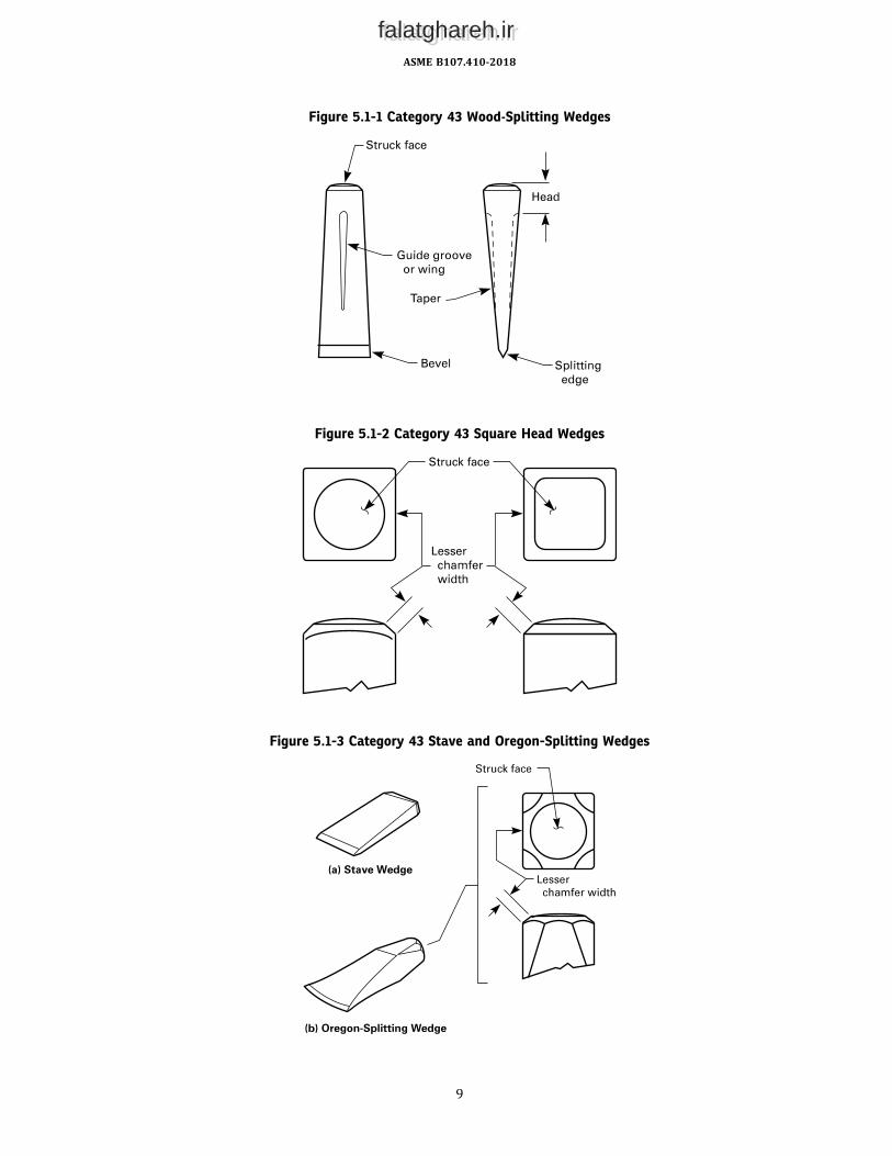
Figure 5.1-1 Category 43 Wood-Splitting Wedges
Figure 5.1-2 Category 43 Square Head Wedges
Figure 5.1-3 Category 43 Stave and Oregon-Splitting Wedges
ASME B107.410-2018
9
falatghareh.irfalatghareh.ir

Figure 5.2-1 Category 44 Glaziers’ Chisels
Figure 5.2-2 Category 44 All-Steel Wood Chisels
ASME B107.410-2018
10
falatghareh.irfalatghareh.ir

Figure 5.2-3 Category 44 Wood Chisels
ASME B107.410-2018
11
falatghareh.irfalatghareh.ir

Figure 5.2-4 Category 44 Ripping Chisels
ASME B107.410-2018
12
falatghareh.irfalatghareh.ir

Figure 5.2-5 Category 44 Flooring/Electricians’ Chisels
ASME B107.410-2018
13
falatghareh.irfalatghareh.ir
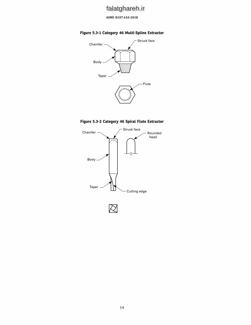
Figure 5.3-1 Category 46 Multi-Spline Extractor
Figure 5.3-2 Category 46 Spiral Flute Extractor
ASME B107.410-2018
14
falatghareh.irfalatghareh.ir

Figure 5.3-3 Category 46 Straight Flute Extractor
Figure 5.3-4 Category 46 Tapered Flute Extractor
ASME B107.410-2018
15
falatghareh.irfalatghareh.ir

Figure 5.4.1-1 Category 48 Type I Chisels
Figure 5.4.1-2 Category 48 Type I Handle-Held Chisels
ASME B107.410-2018
16
falatghareh.irfalatghareh.ir

Figure 5.4.2-1 Category 48 Type II Punches
ASME B107.410-2018
17
falatghareh.irfalatghareh.ir

Figure 5.4.2-2 Category 48 Type II Handle-Held Punches
Figure 5.4.3-1 Category 48 Type III Drift Pins
ASME B107.410-2018
18
falatghareh.irfalatghareh.ir

Figure 5.5.1-1 Category 49 Type I Nail Set
Figure 5.5.2-1 Category 49 Type II (Self-Centering) Nail Set
ASME B107.410-2018
19
falatghareh.irfalatghareh.ir

Figure 5.6-1 Category 50 Brick Chisel and Brick Set
Figure 5.6-2 Configuration of Category 50 Brick Chisel and Brick Set Bevels
ASME B107.410-2018
20
falatghareh.irfalatghareh.ir

Figure 5.6-3 Category 50 Star Drill
ASME B107.410-2018
21
falatghareh.irfalatghareh.ir
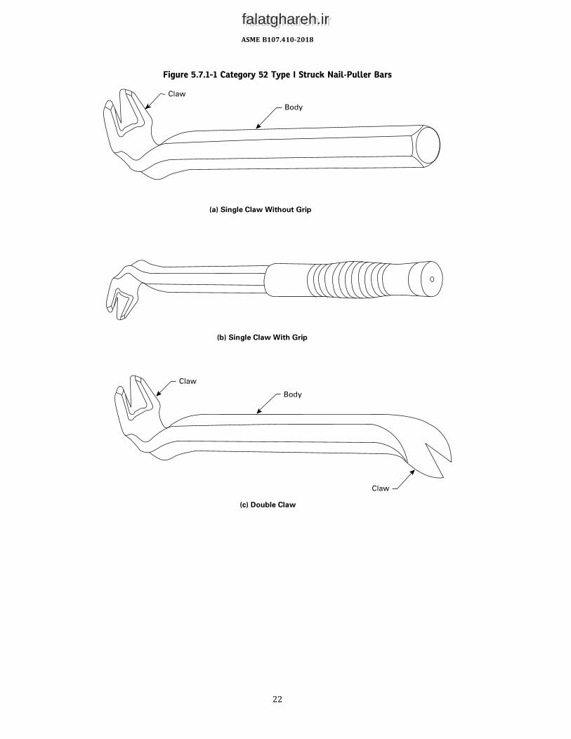
Figure 5.7.1-1 Category 52 Type I Struck Nail-Puller Bars
ASME B107.410-2018
22
falatghareh.irfalatghareh.ir

Figure 5.7.1-2 Category 52 Type II, Class 1 Nonstruck Multipurpose Bar
Figure 5.7.1-3 Category 52 Type II, Class 2 Nonstruck Ripping/Wrecking Bar
Figure 5.7.2-1 Category 52 Type III, Class 1 Close Quarter Pry Bar
Figure 5.7.3-1 Category 52 Type III, Class 2 Die Setter Pry Bar
Figure 5.7.4-1 Category 52 Type III, Class 3 Handled Pry Bar
Figure 5.7.5-1 Category 52 Type III, Class 4 Pinch Bar
ASME B107.410-2018
23
falatghareh.irfalatghareh.ir

Figure 5.8-1 Category 59 Striking Wrenches
Figure 5.8-2 Category 59 Slugging Wrenches
Figure 5.8-3 Struck Block Cross Section
Figure 5.7.6-1 Category 52 Type III, Class 5 Rolling Head Pry Bar
ASME B107.410-2018
24
falatghareh.irfalatghareh.ir

Table 5.9-1 Striking Face and Chamfer
Category 10% of43 Minimum head width44 Body stock size (see Figure 5.2-2)46 Body stock size48 Types I and II Body stock size (see Figures 5.4.1-1 and 5.4.2-1)49 Diameter of the struck face (see Figure 5.5.1-1)50 Diameter of the material behind the struck face (see Figure 5.6-1)59 Struck face width (see Figure 5.8-3)
Table 5.11-1 Hardness Requirements
Category TypeStruck Face,
HRC SurfaceHardness,
HRCDistance,min. From
43 … … Entire tool 35 … …44 I, II 44 … 53–62 0.25 Cutting edge44 III, IV 44 … 30–52 0.25 Cutting edge46 … 43 Cutting edge 45–60 … …48 I 44 … 53–60 0.25 Cutting edge48 II 44 … 48–60 0.25 Point end49 … 44 … 48–60 0.125 Point end50 … 45 … 45 1.00 Struck face50 I, II … … 35–55 0.25 Cutting edge50 III … … 53–60 0.62 Cutting edge52 I … All except heel 55 … …52 I … Heel 44 … …52 II … Entire tool 48 … …52 III … Entire tool 50 … …59 … … Entire tool 44 … …
GENERAL NOTE: A single HRC value is a maximum.
6 TESTS
Many tests required herein are inherently hazardous, and adequate safeguards for personnel and property shall beemployed in conducting such tests. These tests are designed to evaluate the tools and materials and do not condone theuse of the tools in an environment or manner inconsistent with safe use of the tools. Tests shall be conducted at atemperature between 40°F and 90°F. Separate (new) tools shall be used for each test. Failure to meet the requirementsof any applicable test indicates that the tools do not comply with this Standard.
6.1 Hardness Determination Test
Hardness determination shall be made in accordance with ASTM E18.
6.2 Impact Tests
6.2.1 Category 43. The wedge shall be vertically mounted and supported with the splitting edge resting directly on amild steel plate of not less than0.75 in. (19.1mm) thickness. The steel plate shall be rigidly supported on an anvil or othersimilardeviceof sufficientmass to resistdeflection. Prior to conducting this test, care shouldbe taken toblunt the splittingedge to ensure that the impact energy is not expended in deformation of the splitting edge. A steel weight of 10 lb (4.5 kg)with a striking face hardness of 45 HRC to 60 HRC shall be dropped unrestricted from a height of 5.0 ft (1.5 m) onto thewedge a minimum of five times. Typically, the weight is cylindrical and dropped through a seamless tube slightly largerthan the diameter of the weight. The weight shall be dropped in such a manner that each drop applies the full forcesquarely to the struck faceof thewedge.The struck face shall not crackor chip.Normaldeformationof the struck face shallbe permitted.1
1 The test is so severe that a degree of permissible deformation, such as denting of the splitting edge and struck face, can be anticipated. A much lesssevere test would avoid this, but it would not provide the level of safety assurance desired.
ASME B107.410-2018
25
falatghareh.irfalatghareh.ir
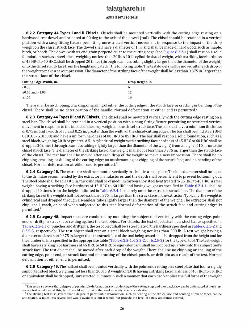
6.2.2 Category 44 Types I and II Chisels. Chisels shall be mounted vertically with the cutting edge resting on ahardwood test dowel and oriented at 90 deg to the axis of the dowel (rod). The chisel should be retained in a verticalposition with a snug-fitting fixture permitting unrestricted vertical movement in response to the impact of the dropweight on the chisel struck face. The dowel shall have a diameter of 1 in. and shall be made of hardwood, such as maple,birch, or beech. The dowel with its end grain perpendicular to the cutting edge (see Figure 6.2.2-1) shall rest on a solidfoundation, suchasa steel block,weighingnot less than20 lb.A10-lb cylindrical steelweight,witha striking facehardnessof 45HRC to 60HRC, shall be dropped 20 times (through seamless tubing slightly larger than the diameter of theweight)onto the chisel struck face fromtheheight indicated in the following table. The testdowel shall bemovedaftereachdropoftheweight tomakeanew impression. Thediameter of the striking faceof theweight shall be less than0.375 in. larger thanthe struck face of the chisel.Cutting Edge Width, in. Drop Height, in.<0.50 6≥0.50 and <1.00 12≥1.00 16
Thereshall benochipping, cracking, or spallingof either thecuttingedgeor thestruck face, or crackingorbendingof thechisel. There shall be no deterioration of the handle. Normal deformation at either end is permitted.2
6.2.3 Category 44 Types III and IV Chisels. The chisel shall be mounted vertically with the cutting edge resting on asteel bar. The chisel shall be retained in a vertical position with a snug-fitting fixture permitting unrestricted verticalmovement in response to the impact of the dropweight on the chisel struck face. The bar shall have aminimum thicknessof 0.75 in. and awidth of at least 0.25 in. greater than thewidth of the chisel-cutting edges. Thebar shall bemild steel (UNSG10180–G10300) and have a uniform hardness of 80 HRB to 85 HRB. The bar shall rest on a solid foundation, such as asteel block, weighing 20 lb or greater. A 5-lb cylindrical weight with a striking face hardness of 45HRC to 60HRC shall bedropped20 times (through seamless tubing slightly larger than thediameter of theweight) fromaheight of 10 in. onto thechisel struck face. The diameter of the striking face of theweight shall not be less than 0.375 in. larger than the struck faceof the chisel. The test bar shall be moved after each drop of the weight to make a new impression. There shall be nochipping, cracking, or dulling of the cutting edge; no mushrooming or chipping of the struck face; and no bending of thechisel. Normal deformation at either end is permitted.2
6.2.4 Category 46.The extractor shall bemounted vertically in a hole in a steel plate. The hole diameter shall be equalto the drill size recommended by the extractor manufacturer, and the depth shall be sufficient to prevent bottoming out.Thesteelplate shall beat least1 in. thickandshall beofmediumcarbonalloy steelheat treated to35HRCto40HRC.Asteelweight, having a striking face hardness of 45 HRC to 60 HRC and having weight as specified in Table 6.2.4-1, shall bedropped 20 times from the height indicated in Table 6.2.4-1 squarely onto the extractor struck face. The diameter of thestriking faceof theweight shall notbe less than0.375 in. larger than the struck faceof theextractor.Typically, theweight iscylindrical and dropped through a seamless tube slightly larger than the diameter of the weight. The extractor shall notchip, spall, crack, or bend when subjected to this test. Normal deformation of the struck face and cutting edges ispermitted.2
6.2.5 Category 48. Impact tests are conducted by mounting the subject tool vertically with the cutting edge, pointend, or drift pin struck face resting against the test object. For chisels, the test object shall be a steel bar as specified inTable6.2.5-1. Forpunchesanddrift pins, the test object shall bea steel plateof thehardness specified inTables6.2.5-2and6.2.5-3, respectively. The test object shall rest on a steel block weighing not less than 200 lb. A test weight having adiameternot less than0.375 in. larger than the struck face of the tool being tested shall bedropped fromtheheight and forthe number of hits specified in the appropriate table (Table 6.2.5-1, 6.2.5-2, or 6.2.5-3) for the type of tool. The testweightshall have a striking facehardness of 45HRC to60HRCor equivalent and shall bedropped squarely onto the subject tool’sstruck face. The test object shall be moved after each drop of the weight. There shall be no chipping or spalling of thecutting edge, point end, or struck face and no cracking of the chisel, punch, or drift pin as a result of the test. Normaldeformation at either end is permitted.3
6.2.6 Category49.Thenail set shall bemountedverticallywith thepoint end restingon a steel plate that is on a rigidlysupported steel blockweighing not less than200 lb. Aweight of 1.0 lb having a striking face hardness of 45HRC to 60HRCor equivalent shall be dropped, unrestricted 20 times in such amanner that each drop applies the full force of theweight
2 This test is so severe that a degree of permissible deformation, such as denting of the cutting edge and the struck face, can be anticipated. Amuch lesssevere test would avoid this, but it would not provide the level of safety assurance desired.3 The striking test is so severe that a degree of permissible deformation, such as denting of the struck face and bending of pin or taper, can be
anticipated. A much less severe test would avoid this, but it would not provide the level of safety assurance desired.
ASME B107.410-2018
26
falatghareh.irfalatghareh.ir

squarely to the struck face. Typically, theweight is cylindrical anddropped through a seamless tubeor pipe slightly largerindiameter than theweight. Fornail setswithapointdiameterup to0.063 in., theweight shall bedropped fromaheightof10.0 in. For point diameters greater than0.063 in., theweight shall bedropped fromaheight of 18.0 in. The test plate shallhave aminimum thickness of 0.25 in.with a uniformhardness of 25HRC to 30HRCor equivalent and shall bemoved aftereachdropof theweight tomakeanew impression. Thepoint endor struck face shall neither chipnor spall, and thenail setshall neither crack nor bend as a result of the test. Normal deformation at either end is permitted.4
6.2.7 Category 50. There shall be no chipping, spalling, cracking, dulling, or turning of the cutting edge; no mush-rooming or chipping of the head (struck face); and no bending of the tool when tested according to the following proce-dure. Normal deformation at either end of the tool is permitted.4
6.2.7.1 Type I Brick Chisels. The brick chisel shall be mounted vertically with the cutting edge resting crosswise onthe largest surface of a rectangular common brick having aminimum thickness of 2.0 in. and awidth of at least 3.0 in. Thebrick shall rest ona solid foundation that supports the entirebrick surface, suchasablockweighingnot less than10.0 lb. Asteelweightof5.0 lb andhavinga striking facehardnessof 45HRC to60HRCorequivalent shall bedropped20 times fromaheight of 10.0 in. squarely onto the chisel struck face. Thediameter of the striking face of theweight shall not be less than0.375 in. larger than the struck face of the chisel. Typically, theweight is cylindrical and dropped through a seamless tubeslightly larger than the diameter of theweight. The test brick shall bemoved after each drop of theweight tomake a newimpression.
6.2.7.2 Type IBrick Chisels.The impact test for brick sets shall be the sameas the test in para. 6.2.7.1, except that theweight shall be dropped ten times.
6.2.7.3 Type II Brick Sets. The star drill shall bemounted vertically with the cutting edges resting on solid concrete.Thestruck faceof the stardrill shall be struck repeatedlybyahammerof theappropriate typeandsizeuntil aholeof0.5 in.± 0.1 in. in depth has been attained. The star drill should be rotated slightly after each successive hit. Three holes shall bedrilled.
6.2.8 Category 52 Tools With Handles. The test plate shall have a hardness of 45 HRC to 50 HRC and shall rest on asolid foundation. The striking weight shall fall freely through a seamless tube having an inner dimension slightly largerthan the weight. The striking face of the weight shall have aminimum hardness of 54 HRC. Impact each sample 20 times.Assembled pry bar handles shall not break, crack, nor significantly distort, which, for the purpose of this test, means anincrease of at least 5% in the handle diameter, either as a uniform or an irregular bulge (see Table 6.2.8-1 and Figure6.2.8-1).
6.2.9 Category59.Samplewrenches shall be subjected to the impact test in para. 6.2.9.1 orpara. 6.2.9.2, dependingonthe style of wrench. All three wrenches shall be evaluated at the conclusion of the test. The struck block of the wrenchesshall not crack or chip. There shall be no visible bending of the shank or twisting of the box ends in excess of 5 deg. Thereshall be no cracks evident on any portion of the wrenches. The wrench openings shall not slip on the mandrel. Normaldeformation of the struck face and the box end of the wrenches is permitted.5
6.2.9.1 Type I Slugging Wrench. Three samples of the same style and size slugging wrench shall be mounted on ahexagonalmandrelwith themiddlewrenchoffset30degwith respect to theotherwrenches.Thehexagonalmandrel shallmeet the requirements of ASME B107.100, as applicable. Steel shims 0.25 in. thick shall be placed under the heads of thetwo wrenches on the ends of the mandrel and the assembly clamped at each of these heads to a rigidly supported steelblock weighing not less than 400 lb. The drop weight shall have a striking face hardness of not less than 45 HRC orequivalent normore than 60HRC or equivalent and shall be dropped squarely onto the struck face of themiddlewrench.Thestriking facediameterof thedropweight shall notbe less than0.375 in. larger than thestruck facewidthof thewrenchbeing struck (see Figure 5.8-3). Typically, the drop weight is cylindrical and dropped through a seamless tube slightlylarger in diameter. Drop weights and drop heights are listed in Table 6.2.9.1-1. The drop weight shall be dropped 100times onto the struck face of the middle wrench (see Figure 6.2.9.1-1 for illustration of impact test setup). Alternatemethods of striking the wrench may be used if the required impact energy in Table 6.2.9.1-1 is satisfied.
4 The striking test is so severe that a degree of permissible deformation, such as denting of the struck face, can be anticipated. Amuch less severe testwould not cause this, but it would not provide the level of safety assurance desired.5 The test is so severe that a degree of permissible deformation, such as the denting of the box end wrenching surfaces and the struck face, can be
anticipated. A much less severe test would avoid this, but it would not provide the level of safety assurance desired.
ASME B107.410-2018
27
falatghareh.irfalatghareh.ir

6.2.9.2 Type II Striking Wrench.Three samples of the same style and sizewrench shall bemounted and tested usingthe same apparatus and method used in para. 6.2.9.1, except the drop weight shall be dropped 20 times onto the struckface of the middle wrench. Drop weights and drop heights are listed in Table 6.2.9.1-1. Alternate methods of striking thewrench may be used if the required impact energy in Table 6.2.9.1-1 is satisfied.
6.3 Tensile Force Test
For Category 44 chisels with separate handles, the chisel blade and handle shall not loosen when subjected to a 60-lbftensile force applied at room temperature.AssembledCategory52prybarhandles shall notbreak, loosen, or separate fromtheprybarwhensubjected to the force
specified in Table 6.3-1.
6.4 Side Force Test
This test applies only to Category 44 Types I and II chisels. There shall be no evidence of breaks, cracks, or permanentdeformation when a side force as indicated in the following table is applied perpendicular and then parallel to the bladeflats at 0.50 in. from the struck face, with the blade rigidly supported 1.5 in. from the cutting edge (see Figure 6.4-1).Cutting Edge Width, in. Side Force, lbf<0.50 10≥0.50 and <1.00 20≥1.00 and <1.50 30≥1.50 50
6.5 Permanent Set
6.5.1 Category 44 Type III Ripping Chisels. Samples shall be supported as shown in Figure 6.5.1-1 and a bendingmoment of 4,500 lbf-in. applied. After application of the bending moment, the sample shall be removed from thesupporting fixture and measured for permanent set. Permanent set is determined by measuring the vertical displace-ment, relative to thehorizontal plane through the centerlineof the sample, of a fixedpoint on the chisel handle (preferablynear the struck face end of the chisel) and dividing the displacement by the distance from the fulcrum. Samples pass thistest only if all of the following conditions are met after loading the tool:(a) The sample does not fracture.(b) The sample does not permanently deform more than 0.1 in./in.
6.5.2 Category 44 Type IV Flooring/Electricians’Chisels. Samples shall be supported as shown in Figure 6.5.1-1 andabendingmomentof2,000 lbf-in. applied. After applicationof thebendingmoment, the sample shall be removed fromthesupporting fixture and measured for permanent set. Permanent set is determined by measuring the vertical displace-ment, relative to thehorizontal plane through the centerlineof the sample, of a fixedpoint on the chisel handle (preferablynear the struck face end of the chisel) and dividing the displacement by the distance from the fulcrum. Samples pass thistest only if both of the following conditions are met after loading the tool:(a) The sample does not fracture.(b) The sample does not permanently deform more than 0.01 in./in.
6.6 Bending Moment Test for Category 48 Type II, Class 4 Drift or Lining-Up Punches
With thepunchsupportednotmore than0.25 in. fromthepoint end,pivotedonacylindrical fulcrumthat is locatedone-third of the taper length from the point end, a bendingmoment is applied by a static force at themidpoint of the bodywiththe force acting substantially at right angles to the axis of the body. The diameter of the fulcrum shall be approximatelytwice that of the punch cross section at the point of contact and oriented at right angles to the axis of the punch. Thepunchmust show at least 20-deg permanent deformation without fracture (see Figure 6.6-1).
6.7 Handle Static Force Test
Handles of assembled Category 48 chisels and punches shall not break, loosen, or otherwise fail when subjected to aforce of 150 lbf while(a) the chisel or punch body is locked securely in the test fixturewith the struck face up and the handle extended in the
horizontal plane(b) the static force is applied vertically at a point on the handle measuring 10 in. from the top of the tool (see Figures
6.7-1 and 6.7-2)
ASME B107.410-2018
28
falatghareh.irfalatghareh.ir

6.8 Nail-Pulling Test — Category 52
6.8.1 Type I. Six commonunhardenednails (16d) corresponding to ASTMF1667designation F1667NLCMS-11B shallbe driven into a softwoodboardwith aminimumthickness of 3.5 in. so that the nailheads are flushwith the board surface.Usinganappropriate sizeball peen, handdrilling, or engineer’shammer (seeTable2-1), the clawendof thenail-pullerbaris to be driven into the wood under the nailheads by striking the heel so that the V-shaped opening grips the nail shanks.Eachnail is tobecompletely removed fromthewoodbysuccessivelyengaging thenail shankwith theV-shapedopeningofthe claw. There shall be no cracks or bending of the claw or tips and no cracking or chipping of the V-shaped opening.
6.8.2 Type II, Class 1 Multipurpose.Eachnail-pulling slot or opening shall completely remove six two-penny commonnails driven into softwoodboardwith aminimumthicknessof 0.63 in. so that thenailheadsarewithin0.13 in. of theboardsurface. Successive pryingusing shimsmaybe required. The test shall be repeated for everyV-shapedopeningor slot thatis designed to pull nails. The pry bar shall not permanently deform or break.
6.8.3 Type II, Class 2 Wrecking/Ripping. Six common unhardened nails (16d) corresponding to ASTM F1667 des-ignation F1667 NLCMS-11B shall be driven into a softwood board with a minimum thickness of 3.5 in. so that thenailheads are within 0.25 in. of the board surface. The pry bar shall be positioned so that the V-shaped openingengages the nail shank immediately beneath the nailhead. Each nail shall be completely removed from the woodby applying force to the pry bar. Successive prying using shims may be required. The test shall be repeated forevery V-shaped opening or slot that is designed to pull nails. The pry bar shall not permanently deform or break.
6.9 Category 52 Type II Prying Test
Each endof the nail-puller bar shall be testedwith the load applied as close to the opposite end as practical, as shown inFigure 6.9-1, illustrations (a) and (b). Apply a slow, steady load to the nail-puller bar tomeet the torque specified in Table6.9-1. If the blade or tip fails or takes a permanent set, the nail-puller bar has failed this test.
6.10 Category 52 Type III Prying Tests
6.10.1 Prying End Test. The load shall be applied near the middle of the handle or grip area of the pry bar [see Figure6.9-1, illustration (c)]. Apply a slow, steady load to the pry bar to the torque specified in Table 6.10.1-1. If the blade or tipfails, takes a permanent set, or if the handle loosens from the pry bar, the pry bar has failed this test.
6.10.2 Point End Test. The load shall be applied near the middle of the grip area of the pry bar (see Figure 6.10.2-1).Apply a slow, steady load to the pry bar to the minimum bend angle specified in Table 6.10.2-1. The pry bar shall notfracture before the minimum bend angle is achieved.
6.11 Category 52 Handle Solvent Resistance Test
Assembled pry bar handles shall be fully immersed in the test fluids specified (new samples shall be used for each testfluid) for 15min to 20min at room temperature, removed, and let stand for 24hr to 28hr. Test fluids are SAE J1703brakefluid, gasoline, ethylene glycol, and ethyl alcohol. There shall be no significant swelling nor surface attack of thematerialbeing tested.
ASME B107.410-2018
29
falatghareh.irfalatghareh.ir

Figure 6.2.2-1 Impact Test for Category 44 Types I and II Chisels
Table 6.2.4-1 Category 46 Impact Test Parameters
Extractor— Corresponding Drill Size, in. [Note (1)] Drop Weight, lb Drop Height of Weight, in.1∕16 1.0 1.03∕32 1.0 2.01∕8 1.0 5.05∕16 1.0 10.03∕16 2.5 10.0
7∕32 2.5 20.01∕4 2.5 30.05∕16 5.0 25.03∕8 5.0 35.07∕16 10.0 22.0
1∕2 10.0 27.55∕8 20.0 19.03∕4 20.0 24.0
NOTE:(1) Sizes other than those listed shall be tested to the next smaller drill size.
ASME B107.410-2018
30
falatghareh.irfalatghareh.ir

Table 6.2.5-1 Impact Test Parameters — Category 48 Type I Chisels
ChiselClass
Cutting EdgeWidth, in.
Drop Weight,lb
Drop Heightof Weight, in.
Number ofHits
Test BarShape and Material Hardness
1, 2, and 3 <0.375 10 6 20 0.25-in. diameter rod,AISI 01
33–35 HRC
0.375 to <0.56 10 20 20 0.25-in. diameter rod,AISI 01
33–35 HRC
≥0.56 10 30 20 0.25-in. diameter rod,AISI 01
33–35 HRC
4 and 5 All sizes 5 10 10 Rectangular, 0.75-in.minimum thicknessand at least 0.25 in.wider than chisel-cutting edge,SAE-AISI 1018–1030
80–85 HRB
1.0 All sizes 10 40 10 Rectangular, 0.75-in.minimum thicknessand at least 0.25 in.wider than chisel-cutting edge,SAE-AISI 1018–1030
25–30 HRC
GENERAL NOTE: For further information about AISI designations, contact American Iron and Steel Institute, 2000 Town Center, Southfield, MI48075 (www.steel.org).
ASME B107.410-2018
31
falatghareh.irfalatghareh.ir

Table 6.2.5-2 Impact Test Parameters — Category 48 Type II Punches
PunchClass
Nominal Point Size,in. [Note (1)]
Drop Weight,lb
Drop Height ofWeight, in.
Numberof Hits
Test PlateHardness, HRC
1 and 7 (backing-out) 3∕8 to <5∕8 20 25 20 45–50≥5∕8 20 30 20 45–50
2 (bearing race) 7∕16 × 15∕64 20 15 20 45–501∕2 × 17∕64 20 20 20 45–509∕16 × 19∕64 20 25 20 45–505∕8 × 9∕16 20 30 20 45–50
3 (center) <3∕16 5 10 20 25–30≥3∕16 5 15 20 25–30
4 (drift or lining-up) 3∕32 5 5 20 45–501∕8 5 10 20 45–503∕16 5 20 20 45–501∕4 5 20 20 45–505∕16 10 20 20 45–503∕8 10 20 20 45–50
5 (pin) 1∕16 1 5 20 45–503∕32 1 7 20 45–501∕8 2.5 10 20 45–505∕32 5 10 20 45–503∕16 5 20 20 45–507∕32 5 30 20 45–501∕4 10 25 20 45–505∕16 10 30 20 45–503∕8 10 30 20 45–50
6 (prick) All sizes 5 5 20 25–30
8 (starting) 1∕16 1 20 20 45–503⁄32 2.5 10 20 45–501∕8 5 10 20 45–503∕16 10 15 20 45–507∕32 10 20 20 45–501∕4 10 35 20 45–50
NOTE: (1) Sizes other than those listed are tested to the next smaller point size.
ASME B107.410-2018
32
falatghareh.irfalatghareh.ir
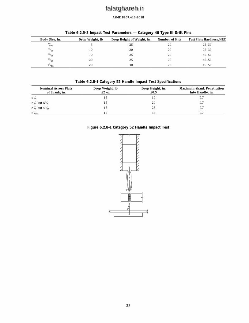
Table 6.2.5-3 Impact Test Parameters — Category 48 Type III Drift Pins
Body Size, in. Drop Weight, lb Drop Height of Weight, in. Number of Hits Test PlateHardness, HRC9∕16 5 25 20 25–3011∕16 10 20 20 25–3013∕16 10 25 20 45–5015∕16 20 25 20 45–5011∕16 20 30 20 45–50
Table 6.2.8-1 Category 52 Handle Impact Test Specifications
Nominal Across Flatsof Shank, in.
Drop Weight, lb±2 oz
Drop Height, in.±0.5
Maximum Shank PenetrationInto Handle, in.
≤1∕4 15 10 0.7>1∕4 but ≤3∕8 15 20 0.7>3∕8 but ≤7∕16 15 25 0.7>7∕16 15 35 0.7
Figure 6.2.8-1 Category 52 Handle Impact Test
ASME B107.410-2018
33
falatghareh.irfalatghareh.ir

Table 6.2.9.1-1 Category 59 Impact Test Specifications
Wrench StyleNominal WrenchOpening, in. Drop Weight, lb Drop Height, ft Impact Energy, ft-lbf
Slugging (offset andstraight shank),Types I and II
<2 10 10 100≥2 but <23∕4 15 10 150≥23∕4 24 15 360
Striking, Type III <15∕8 5 5 25≥15∕8 but <23∕8 10 5 50≥23∕8 10 10 100
Figure 6.2.9.1-1 Impact Test Setup
ASME B107.410-2018
34
falatghareh.irfalatghareh.ir

Figure 6.4-1 Category 44 Side Force Test
Table 6.3-1 Category 52 Handle Tensile Force Test Loads
Nominal Across Flatsof Shank, in. Minimum Load, lb
≤1∕4 150>1∕4 but ≤3∕8 210>3∕8 but ≤7∕16 275>7∕16 475
ASME B107.410-2018
35
falatghareh.irfalatghareh.ir

Figure 6.5.1-1 Category 44 Permanent Set Test
Figure 6.6-1 Category 48 Bending Moment Test
ASME B107.410-2018
36
falatghareh.irfalatghareh.ir

Figure 6.7-1 Static Force Test for Category 48 Handle-Held Punches
Figure 6.7-2 Static Force Test for Category 48 Handle-Held Chisels
ASME B107.410-2018
37
falatghareh.irfalatghareh.ir

Figure 6.9-1 Prying Test
ASME B107.410-2018
38
falatghareh.irfalatghareh.ir

Table 6.9-1 Category 52 Type II Prying End Test Specifications
Nail-Puller Bar Type II Nominal Overall Length, in. Minimum Torque, lbf-in.Class 1 multipurpose <8 ...
≥8 2,000
Class 2 ripping/wrecking ≤15 1,200>15 but ≤21 2,100>21 2,600
Table 6.10.1-1 Category 52 Type III Prying End Test Specifications
Type III Pry Bar Class Nominal Overall Length, in. Minimum Torque, lbf-in.Class 1 close quarter ≤12 280
>12 but ≤17 700>17 but ≤20 800>20 1,500
Class 2 die setter ... 2,600
Class 3 pry bar with handle ≤10 500>10 but ≤15 1,200>15 but ≤21 1,400>21 but ≤28 1,600>28 2,900
Class 4 pinch ≤14 460>14 but ≤15.5 650>15.5 but ≤24 1,800>24 but ≤33 2,800>33 5,100
Class 5 rolling head (rolling head end) ≤9 500>9 but ≤14 1,200>14 but ≤18 1,400>18 1,600
ASME B107.410-2018
39
falatghareh.irfalatghareh.ir

Figure 6.10.2-1 Point End Test
Table 6.10.2-1 Category 52 Point End Test Specifications
Type III Pry Bar Class Nominal Length, in. Minimum Bend Angle, degClass 1 close quarter All 30Class 4 pinch All 30Class 5 rolling head ≤6 20... All others 30
GENERAL NOTE: Insertion to midpoint of taper ±0.13.
ASME B107.410-2018
40
falatghareh.irfalatghareh.ir

7 SAFETY REQUIREMENTS AND LIMITATIONS OF USE
7.1 Safety Requirements
(a) Instructors and employers shall stress proper use and safety in the use of struck tools; they shall emphasize theneed to wear and ensure the use of safety goggles. The publication Guide to Hand Tools— Selection, Safety Tips, ProperUse and Care provides guidelines for the safe use of these tools.(b) To avoid possible eye injury from flying objects, safety goggles or equivalent eye protection conforming to ANSI/
ISEA Z87.1 shall be worn by the user and all persons in the immediate area where any struck tool is being used.(c) Struck tools shall be free of nonfunctional sharp edges, points, and surface roughness that could inflict personal
injury on the user when handling the tool. They shall be free of manufacturing and material defects, such as seams, laps,pipes, or coldshuts, thatwould jeopardize soundconstructionandbeessentially free frompits, nodules, burrs, cracks, andother conditions that would adversely affect the performance or safety of the tool.
7.1.1 Inspection
(a) Struck tools shall be inspected prior to each use and their use discontinued at the first sign of bending, mush-rooming, chipping, or cracking of any portion of the body, struck face, or cutting edge.(b) Handles shall be inspectedprior to eachuse, and thosedamaged shall be replaced. Thehandles of tools shall be free
of splinters or cracks and kept tight in the tool. Replacements shall withstand applicable tests and be equivalent to theoriginal handle in size and quality.
7.1.2 Redressing
(a) No part of a struck tool shall be ground, welded, treated by reheating, or otherwise altered from the originalconditions as furnished by the manufacturer, except for the following conditions:
(1) Dulling of the splitting edge, cutting edge, or point end may occur from tool usage. It shall be reshaped orredressed to the original contour only by the use of a whetstone or hand file.6
(2) At the first indicationofmushrooming, the struck face and struck face chamfer (if present) of the struck tool shallbe redressed to its original contour by the use of a hand file or whetstone.7(b) Handle grips that have loosened shall be repaired or replaced.
7.1.3 Marking. Each struck tool, size permitting, shall be stamped, labeled, or otherwise marked by the manufacturerwith the following safety message or equivalent:
©ISO. Graphic image is reproduced from ISO 7010:2011 with permission of the American National Standards Institute (ANSI) on behalf of theInternational Organization for Standardization. All rights reserved.
Pictorials are an acceptable equivalent. This safetymessage shall be located in a position thatwill not interferewith thequality or performance of the tool. The principles set forth in ANSI Z535.4 shall be used as the guide for alternate,equivalent methods of labeling.
7.2 Limitations of Use
7.2.1 IntendedUseOnly.Toavoidpossibleeyeorotherbodily injury, the tools coveredhereinshall beusedonly for thepurposes specified in Table 1-1 and the following:6 It is understood that industrial userswithadequate facilities andproperly trainedpersonnelmay choose to redressor resharpen these toolsbyother
means without altering the metallurgical characteristics of the tools.7 It is understood that industrial users with adequate facilities and properly trained personnel may choose to redress the struck face and struck face
chamfer of these tools by other means without altering the metallurgical characteristics of the tools.
ASME B107.410-2018
41
falatghareh.irfalatghareh.ir

(a) Category 46 screw and pipe extractors are special-purpose tools designed and intended only for removing brokenscrews,pipes, bolts, studs, and fittings fromthreadedopenings.Theyare intendedonly for removing threadedmetalpipesand fasteners that are of softer material than the extractor. An initial cautious blowmay be used to ascertain the relativedifference in hardness of the extractor and object being removed.(b) Category 48 Type I metal chisels are special-purpose tools designed and intended for the cutting, shaping, and
removing of metal softer than the cutting edge of the chisel itself. Such softer materials include cast iron, wrought iron,steel, bronze, copper, and the like. An initial cautious blow may be used to ascertain the relative hardness of the stuckobject with subsequent examination of the cutting edge.(c) Category 52 Type I nail-puller bars are special-purpose tools designed and intended only for the specific use of
extracting embedded nails fromwood. The claw is intended to be driven into the wood under a nailhead by striking theheel with an appropriate striking tool.(d) Category 52 Type III pry bars are special-purpose tools designed and intended only for the specific use of sep-
arating, prying, ripping, lifting, scraping, and aligning applications.(e) Category 59 slugging and striking wrenches are special-purpose tools designed and intended only for use with
heavy-duty fasteners where shock or impact is needed to fully tighten or loosen (see Table 1-1).
7.2.2 Specific Use Limitations
(a) Only an appropriate striking tool shall be used to strike struck tools. A blow from an appropriate striking tool shallbe struck squarely, with the striking face parallel with the struck face of the struck tool.(b) A woodchopper’s maul or an ax shall always be used to make a starting notch in the wood to be split.(c) Extractors shall always be used with hole sizes as specified in the manufacturer’s instructions.(d) When using a wrench to turn an extractor, the user shall always pull on the handle and adopt a stance that will
prevent a fall in the event of a sudden tool or fastener failure.(e) Whenusing a pin, round, starting, or backing-out punch, the point end diameter of the punch shall approximate the
size of the pin or rivet being driven.(f) Chisels andpuncheswith handles shall not be swungagainst theworkbut rather held by thehandlewith the tool on
the work and struck with an appropriate striking tool.(g) The body of a self-centering nail set shall be placed over the protruding unhardened nail and the punch struckwith
the appropriate striking tool to set the nail below the surface of the material being nailed.(h) Care shall be exercised to prevent a Category 59 wrench from dislodging from the fastener or nut while being
impacted.
7.2.3 Unintended Use
(a) Glancing blows, overstrikes, and understrikes should be avoided. No surface of the tool other than the struck faceshall be struck.(b) Wood-splitting wedges shall not be struck with an ax or hatchet.(c) Glaziers’ and wood chisels shall not be used for wedging.(d) Extractors shall not be used as a punch, pry bar, or wedge.(e) Category 48 chisels and Category 50 brick chisels, brick sets, and star drills shall not be used for prying orwedging.(f) Prick, center, pin, backing-out, and round punches shall not be used for prying or wedging. Pin, prick, and center
punches shall not be used as starting punches. Prick and center punches shall not be used for driving pins.(g) Drift or lining-up punches and drift pins shall not be used for driving metal or other hard objects.(h) Nail sets shall not be used for prying, wedging, or aligning holes.(i) Brick chisels, brick sets, or star drills shall never be struck by a bricklayer’s hammer.(j) A nail hammer shall not be used to strike a nail-puller bar. (The striking face is too small and may chip.)(k) Type II nail-puller bars are not intended to be struck.(l) A pry bar is not intended to be struck.(m) A pipe extension or other form of “cheater” to increase the leverage of any bar or wrench shall never be used.(n) To avoid possible eye and other bodily injury(1) glaziers’ chisels,woodchisels, and flooring/electricians’ chisels shall notbeused to cutmetal ormasonryobjects(2) extractors shall not be used to extract objects as hard as or harder than the extractor cutting edges(3) chisels shall not be used to cut objects as hard or harder than the chisel cutting edge, such as stone or concrete(4) nail sets shall not be used to strike hard or hardened objects, such as rocks, bricks, concrete, masonry nails, and
other hardened nails or steel tools(5) brick chisels and brick sets shall not be used to cut metal objects or concrete
ASME B107.410-2018
42
falatghareh.irfalatghareh.ir

B107 AMERICAN NATIONAL STANDARDS FOR HAND TOOLS
B107.4-2018 Driving and Spindle Ends for Portable Hand, Impact, Air, and Electric Tools(Percussion Tools Excluded)
B107.17-2010 Gages and Mandrels for Wrench OpeningsB107.56-2018 Body Repair ToolsB107.100-2010 Flat WrenchesB107.110-2012 Socket Wrenches, Handles, and AttachmentsB107.300-2010 (R2016) Torque InstrumentsB107.400-2018 Striking ToolsB107.410-2018 Struck ToolsB107.500-2010 PliersB107.600-2016 Screwdrivers and Screwdriver Bits
TheASMEPublications Catalog shows a complete list of all the Standards publishedby the Society. For a complimentary catalog, orthe latest information about our publications, call 1-800-THE-ASME (1-800-843-2763).
falatghareh.irfalatghareh.ir

ASME Services
ASME is committed to developing and delivering technical information. At ASME’s Customer Care, we make every effort to answer yourquestions and expedite your orders. Our representatives are ready to assist you in the following areas:
ASME Press Member Services & Benefits Public InformationCodes & Standards Other ASME Programs Self-Study CoursesCredit Card Orders Payment Inquiries Shipping InformationIMechE Publications Professional Development Subscriptions/Journals/MagazinesMeetings & Conferences Short Courses Symposia VolumesMember Dues Status Publications Technical Papers
How can you reach us? It’s easier than ever!
Thereare fouroptions formaking inquiries* orplacingorders. Simplymail, phone, fax, orE-mail us andaCustomerCare representativewill handleyour request.
Mail Call Toll Free Fax—24 hours E-Mail—24 hoursASME US & Canada: 800-THE-ASME 973-882-1717 [email protected] Clove Road, 6th Floor (800-843-2763) 973-882-5155Little Falls, New Jersey Mexico: 95-800-THE-ASME07424-2139 (95-800-843-2763)
*Customer Care staff are not permitted to answer inquiries about the technical content of this code or standard. Information as to whether or nottechnical inquiries are issued to this code or standard is shownon the copyright page. All technical inquiriesmust be submitted inwriting to thestaff secretary. Additional procedures for inquiries may be listed within.
falatghareh.irfalatghareh.ir

ASME B107.410-2018
falatghareh.irfalatghareh.ir